EP2181867A1 - Tyre-changing machine for fitting and removing vehicle wheels - Google Patents
Tyre-changing machine for fitting and removing vehicle wheels Download PDFInfo
- Publication number
- EP2181867A1 EP2181867A1 EP09173532A EP09173532A EP2181867A1 EP 2181867 A1 EP2181867 A1 EP 2181867A1 EP 09173532 A EP09173532 A EP 09173532A EP 09173532 A EP09173532 A EP 09173532A EP 2181867 A1 EP2181867 A1 EP 2181867A1
- Authority
- EP
- European Patent Office
- Prior art keywords
- machine
- tyre
- rim
- operating
- wheel
- Prior art date
- Legal status (The legal status is an assumption and is not a legal conclusion. Google has not performed a legal analysis and makes no representation as to the accuracy of the status listed.)
- Granted
Links
- 238000001514 detection method Methods 0.000 claims abstract description 19
- 230000003287 optical effect Effects 0.000 claims description 3
- 239000003086 colorant Substances 0.000 claims description 2
- 230000002401 inhibitory effect Effects 0.000 claims description 2
- 239000011324 bead Substances 0.000 description 10
- 229910000967 As alloy Inorganic materials 0.000 description 1
- 238000000605 extraction Methods 0.000 description 1
- 238000012423 maintenance Methods 0.000 description 1
- 239000000463 material Substances 0.000 description 1
- 239000002184 metal Substances 0.000 description 1
- 238000000034 method Methods 0.000 description 1
- 238000006748 scratching Methods 0.000 description 1
- 230000002393 scratching effect Effects 0.000 description 1
- 238000012876 topography Methods 0.000 description 1
Images
Classifications
-
- B—PERFORMING OPERATIONS; TRANSPORTING
- B60—VEHICLES IN GENERAL
- B60C—VEHICLE TYRES; TYRE INFLATION; TYRE CHANGING; CONNECTING VALVES TO INFLATABLE ELASTIC BODIES IN GENERAL; DEVICES OR ARRANGEMENTS RELATED TO TYRES
- B60C25/00—Apparatus or tools adapted for mounting, removing or inspecting tyres
- B60C25/01—Apparatus or tools adapted for mounting, removing or inspecting tyres for removing tyres from or mounting tyres on wheels
- B60C25/05—Machines
- B60C25/132—Machines for removing and mounting tyres
- B60C25/135—Machines for removing and mounting tyres having a tyre support or a tool, movable along wheel axis
- B60C25/138—Machines for removing and mounting tyres having a tyre support or a tool, movable along wheel axis with rotary motion of tool or tyre support
-
- B—PERFORMING OPERATIONS; TRANSPORTING
- B60—VEHICLES IN GENERAL
- B60C—VEHICLE TYRES; TYRE INFLATION; TYRE CHANGING; CONNECTING VALVES TO INFLATABLE ELASTIC BODIES IN GENERAL; DEVICES OR ARRANGEMENTS RELATED TO TYRES
- B60C25/00—Apparatus or tools adapted for mounting, removing or inspecting tyres
- B60C25/01—Apparatus or tools adapted for mounting, removing or inspecting tyres for removing tyres from or mounting tyres on wheels
- B60C25/05—Machines
- B60C25/0548—Machines equipped with sensing means, e.g. for positioning, measuring or controlling
- B60C25/0554—Machines equipped with sensing means, e.g. for positioning, measuring or controlling optical, e.g. cameras
Definitions
- the present invention relates to a tyre-changing machine for fitting and removing vehicle wheels.
- vehicle wheels are composed of a cylindrical metal rim having, at the axial extremities, annular flanges between which a channel for the slot-in fitting of an elastic tyre is defined.
- an inner tube Inside the tyre, an inner tube can be fitted or, in the case of "tubeless" type tyres, air under pressure can be introduced directly.
- tyre-changing machines which allow removing the tyre from the relevant rim, e.g., to perform maintenance jobs or replace the inner tube, the rim and/or the tyre itself, and then fit the same tyre, or a replacement tyre, back on the wheel rim.
- tyre-changing machines are composed of a base frame that supports gripping and rotating means of the wheel rim being worked.
- the rotation axis of the gripping and rotating means can be vertical or horizontal according to the type of tyre-changing machine.
- one or more operating heads having one or more tools for fitting and/or removing the tyre onto and from the rim.
- the tools used have different shapes and dimensions according to their intended use.
- Some tools for example, have a hook shape and are intended to be fitted between the beads of the tyre and the corresponding annular flanges of the rim to detach them, during removal, and to press the beads inside the channel defined between the annular flanges, during fitting.
- the operating heads fitted on the tyre-changing machine are usually associated with automated operating means, such as pneumatic cylinders, hydraulic cylinders or the like, which perform the fitting and removal operation with greater force than a human being.
- automated operating means such as pneumatic cylinders, hydraulic cylinders or the like, which perform the fitting and removal operation with greater force than a human being.
- the operator operates the machine by means of the operating commands that control the movement of the operating heads and the exact operation of the machine is obtained by means of the correct control of the tools.
- Machines made this way are susceptible to upgrading aimed at making them more practical to use and more precise in performing the fitting and removal operations.
- the main aim of the present invention is to provide a tyre-changing machine for fitting and removing vehicle wheels that is practical and functional to use and permits making it easier for the operator to perform the fitting and removal operations to the point of also being able to be used by non-skilled personnel, thus providing a considerable economic saving in terms of lower labour costs.
- Another object of the present invention is to provide a tyre-changing machine for fitting and removing vehicle wheels that allows to overcome the mentioned drawbacks of the background art in the ambit of a simple, rational, easy, effective to use and low cost solution.
- this tyre-changing machine for fitting and removing vehicle wheels, comprising a base frame supporting gripping and rotating means for at least one wheel of vehicles with a rim and a tyre to be fitted/removed, at least an operating head associable with said base frame and having at least a fitting/removal tool, operating means suitable for positioning said operating head in a work configuration in which said tool is arranged in contact against said tyre substantially near the flange of said rim, characterized in that it comprises detection means without contact of said flange of the rim, which are operatively associated with at least one processing and control unit suitable for the control/aid of said operating means for the positioning of said operating head in said work configuration.
- the machine 1 comprises a base frame 2 supporting gripping and rotating means 3 of a wheel R for vehicles.
- the wheel R is composed of an inner rim C and of a tyre P to be fitted and/or removed onto/from the rim C.
- the base frame 2 comprises a base 2a above which the gripping and rotating means 3 extend.
- the gripping and rotating means 3 are composed of a vertical-axis spindle, but alternative embodiments cannot be ruled out in which the machine 1 has horizontal-axis gripping and rotating means 3.
- the base frame 2 also comprises a turret 2b that extends vertically from the base 2a and which supports an operating head 4.
- the operating head 4 has a tool 5, 6 for fitting and/or removing the tyre P and is associated with operating means 7, 8, 9, of the automated type, suitable for positioning the operating head 4 in a work configuration in which the tool 5, 6 is arranged in contact against a bead T of the tyre P substantially near the flange B of the rim C.
- the operating head 4 is defined by a substantially horizontal arm that protrudes overhanging from the turret 2b and which has a free extremity at which the tool 5, 6 is fitted.
- the tool 5, 6, in particular, is defined by a hook-shaped tool 5, insertable longitudinally between the bead T of the tyre P and the rim C of the wheel R to grip and extract the bead T, and by a push element 6 designed to be pressed against the bead T to push the wheel R during fitting and removal operations.
- the operating means 7, 8, 9 are schematically shown in figure 1 and comprise:
- the machine 1 has detection means without contact 10 intended to recognise the flange B of the rim C.
- the detection means without contact 10 are operatively associated with a processing and control unit 11 suitable for controlling and/or aiding the operating means 7, 8, 9 to position the operating head 4 in the work configuration.
- processing and control unit 11 is suitable for "controlling" the operating means 7, 8, 9, we mean that the movement of the operating head 4 during the fitting and/or removal operations is completely and independently performed by the machine 1 by means of the processing and control unit 11, without any direct intervention on the part of the operator.
- the processing and control unit 11 is suitable for "aiding" the operating means 7, 8, 9
- the processing and control unit 11 helps the operator while he/she controls the operating means 7, 8, 9, e.g., by slowing down their movements near the flange B of the rim C or by defining a series of end-of-stroke positions for the actuators 7, 8, 9, inhibiting all the commands given by the operator that would move the operating head 4 against the rim C with the risk of damaging it.
- the detection means without contact 10 comprise an identification system of the structured light type.
- the detection means without contact 10 comprise a pattern generator 12 suitable for projecting towards the wheel R an image in itself known to the processing and control unit 11.
- the pattern generator 12 is composed, e.g., of a laser diode with known angular opening which, advantageously, projects a three-dimensional image into space, which means it does not only propagate along a line or a single plane but also along a cone or a pyramid of light.
- the projected image can, e.g., be a pattern of more or less coloured lines 13 which intercept the wheel R and highlight the profile.
- the detection means without contact 10 comprise a detection device 14 for detecting the light generated by reflection by the intersection of the projected image 13 with the wheel R.
- the detection device 14 for example, is composed of an optical sensor, of the CCD (Charge-Couple Device) type or the like, which reproduces the shape of the lines 13 on the wheel R and transfers the data to the processing and control unit 11.
- CCD Charge-Couple Device
- the processing and control unit 11 processes the acquired image 13 to obtain the parameters useful for recognising the flange C and any other parts of the wheel R for their positioning in space.
- the relative distance between the lines 13 allows calculating the distance of the wheel R from the laser diode 12 and therefore collocating the wheel R in the reference system of the machine 1.
- the shape of the lines 13 (curvature, continuity, relative divergence) detected on the wheel R, on the other hand, is compared with the shape of the image originally projected by the laser diode 12 and allows recognising the shape of the lit-up surface and identifying the flange B of the rim C and other major points of the wheel R useful for operating the operating head 4.
- the detection means without contact 10 can also consist of systems other than structured light systems, e.g., an identification system for identifying the colours of the rim C and of the tyre P.
- a camera can be used identical to that previously described and, instead of a laser diode, one or more isotropic illuminators can be used to place the system in controlled conditions (e.g., to overcome the objective limits of ambient light).
- the detection means without contact 10 can consist of a system of identification of the shadows defined on the rim C and on the tyre P by means of the projection of light coming from two or more known points and fixed inside the reference system of the machine 1.
Landscapes
- Engineering & Computer Science (AREA)
- Mechanical Engineering (AREA)
- Tires In General (AREA)
- Automatic Assembly (AREA)
- Length Measuring Devices By Optical Means (AREA)
- Vehicle Cleaning, Maintenance, Repair, Refitting, And Outriggers (AREA)
- Automobile Manufacture Line, Endless Track Vehicle, Trailer (AREA)
- Graft Or Block Polymers (AREA)
Abstract
Description
- The present invention relates to a tyre-changing machine for fitting and removing vehicle wheels.
- It is known that vehicle wheels are composed of a cylindrical metal rim having, at the axial extremities, annular flanges between which a channel for the slot-in fitting of an elastic tyre is defined.
- In fitting configuration, the side portions of the tyre, so-called "beads", are stopped up fast on the annular flanges of the rim.
- Inside the tyre, an inner tube can be fitted or, in the case of "tubeless" type tyres, air under pressure can be introduced directly.
- To perform the tyre fitting and removal operations onto and from the relevant rims, so-called tyre-changing machines are currently used which allow removing the tyre from the relevant rim, e.g., to perform maintenance jobs or replace the inner tube, the rim and/or the tyre itself, and then fit the same tyre, or a replacement tyre, back on the wheel rim.
- Traditionally, tyre-changing machines are composed of a base frame that supports gripping and rotating means of the wheel rim being worked.
- The rotation axis of the gripping and rotating means can be vertical or horizontal according to the type of tyre-changing machine.
- On the base frame are mounted one or more operating heads having one or more tools for fitting and/or removing the tyre onto and from the rim.
- The tools used have different shapes and dimensions according to their intended use.
- Some tools, for example, have a hook shape and are intended to be fitted between the beads of the tyre and the corresponding annular flanges of the rim to detach them, during removal, and to press the beads inside the channel defined between the annular flanges, during fitting.
- Other tools, on the other hand, have a truncated cone or cylindrical shape and are fitted revolving to act as pressing rollers intended to push the tyre beads towards the inside of the rim channel during fitting or towards the outside during removal.
- The operating heads fitted on the tyre-changing machine are usually associated with automated operating means, such as pneumatic cylinders, hydraulic cylinders or the like, which perform the fitting and removal operation with greater force than a human being.
- The operator operates the machine by means of the operating commands that control the movement of the operating heads and the exact operation of the machine is obtained by means of the correct control of the tools.
- Machines made this way however are susceptible to upgrading aimed at making them more practical to use and more precise in performing the fitting and removal operations.
- With traditional machines in fact, the movement of the tools is inconveniently dependant on the professionalism and experience of the operator.
- In particular, it must be noted that the most critical phases for the operator during the performance of the fitting and removal operations on a tyre-changing machine are the following:
- recognising the contact flange of the tyre on the rim and the precise positioning of the tools close to it to perform the following operation phases;
- the operation of the hook tools for removing the tyre from the rim channel without causing excessive stress on the bead or breakages of its inner structure (above all in the case of more delicate tyres such as low profile tyres and runflat tyres) and without touching and scratching the rim (above all in the case of prized rims such as alloy rims).
- More in general therefore, it is underlined that the ability of the operator to recognise the flange of the rim on which the tyre comes into contact and his/her skills in correctly positioning the tools near the flange itself represents a current functional limit of the tyre-changing machines.
- In this respect, furthermore, it is specified that the difficulty in controlling traditional tyre-changing machines inconveniently results in their only being able to be used by skilled and suitably trained personnel at a cost that is not negligible.
- The main aim of the present invention is to provide a tyre-changing machine for fitting and removing vehicle wheels that is practical and functional to use and permits making it easier for the operator to perform the fitting and removal operations to the point of also being able to be used by non-skilled personnel, thus providing a considerable economic saving in terms of lower labour costs.
- Another object of the present invention is to provide a tyre-changing machine for fitting and removing vehicle wheels that allows to overcome the mentioned drawbacks of the background art in the ambit of a simple, rational, easy, effective to use and low cost solution.
- The above objects are achieved by this tyre-changing machine for fitting and removing vehicle wheels, comprising a base frame supporting gripping and rotating means for at least one wheel of vehicles with a rim and a tyre to be fitted/removed, at least an operating head associable with said base frame and having at least a fitting/removal tool, operating means suitable for positioning said operating head in a work configuration in which said tool is arranged in contact against said tyre substantially near the flange of said rim, characterized in that it comprises detection means without contact of said flange of the rim, which are operatively associated with at least one processing and control unit suitable for the control/aid of said operating means for the positioning of said operating head in said work configuration.
- Other characteristics and advantages of the present invention will become more evident from the description of a preferred, but not sole, embodiment of a tyre-changing machine for fitting and removing vehicle wheels, illustrated purely as an example but not limited to the annexed drawings in which:
-
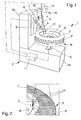
figure 1 is a perspective view of the machine according to the invention; -
figure 2 is a perspective view, on an enlarged scale, of a possible image projected by the machine according to the invention on the wheel being processed. - With particular reference to such figures, globally indicated by 1 is a tyre-changing machine for fitting and removing vehicle wheels.
- The machine 1 comprises a
base frame 2 supporting gripping and rotating means 3 of a wheel R for vehicles. - The wheel R is composed of an inner rim C and of a tyre P to be fitted and/or removed onto/from the rim C.
- In the particular embodiment of the invention shown in the illustrations, the
base frame 2 comprises abase 2a above which the gripping and rotating means 3 extend. - The gripping and rotating
means 3 are composed of a vertical-axis spindle, but alternative embodiments cannot be ruled out in which the machine 1 has horizontal-axis gripping and rotatingmeans 3. - The
base frame 2 also comprises aturret 2b that extends vertically from thebase 2a and which supports anoperating head 4. - The
operating head 4 has atool operating means operating head 4 in a work configuration in which thetool - In the particular embodiment of the invention shown in the illustrations, the
operating head 4 is defined by a substantially horizontal arm that protrudes overhanging from theturret 2b and which has a free extremity at which thetool - The
tool shaped tool 5, insertable longitudinally between the bead T of the tyre P and the rim C of the wheel R to grip and extract the bead T, and by apush element 6 designed to be pressed against the bead T to push the wheel R during fitting and removal operations. - Usefully, the operating means 7, 8, 9 are schematically shown in
figure 1 and comprise: - a
first actuator 7 for moving theoperating head 4 along a direction parallel to the rotation axis of the wheel R and, in detail, along theturret 2b; - a
second actuator 8 for moving theoperating head 4 along a direction at right angles to the rotation axis of the wheel R and, specifically, so as to extend and shorten thearm 4; - a
third actuator 9 for moving theoperating head 4 so as to vary the angle of thetool 5 with respect to the rotation axis of the wheel R to ensure easier gripping and extraction of the bead T during removal operations. - Alternative embodiments cannot however be ruled out in which a plurality of
operating heads 4 are fitted withtools actuators tools means 3 are movable with respect to thetools - Advantageously, the machine 1 has detection means without
contact 10 intended to recognise the flange B of the rim C. - The detection means without
contact 10 are operatively associated with a processing andcontrol unit 11 suitable for controlling and/or aiding the operating means 7, 8, 9 to position theoperating head 4 in the work configuration. - In this respect, it must be pointed out that when we say the processing and
control unit 11 is suitable for "controlling" the operating means 7, 8, 9, we mean that the movement of theoperating head 4 during the fitting and/or removal operations is completely and independently performed by the machine 1 by means of the processing andcontrol unit 11, without any direct intervention on the part of the operator. - When, on the other hand, we say that the processing and
control unit 11 is suitable for "aiding" the operating means 7, 8, 9 we mean that the processing andcontrol unit 11 helps the operator while he/she controls the operating means 7, 8, 9, e.g., by slowing down their movements near the flange B of the rim C or by defining a series of end-of-stroke positions for theactuators operating head 4 against the rim C with the risk of damaging it. - Usefully, the detection means without
contact 10 comprise an identification system of the structured light type. - More in detail, the detection means without
contact 10 comprise apattern generator 12 suitable for projecting towards the wheel R an image in itself known to the processing andcontrol unit 11. - The
pattern generator 12 is composed, e.g., of a laser diode with known angular opening which, advantageously, projects a three-dimensional image into space, which means it does not only propagate along a line or a single plane but also along a cone or a pyramid of light. - The projected image can, e.g., be a pattern of more or less
coloured lines 13 which intercept the wheel R and highlight the profile. - To acquire the shape of this profile, the detection means without
contact 10 comprise adetection device 14 for detecting the light generated by reflection by the intersection of the projectedimage 13 with the wheel R. - The
detection device 14, for example, is composed of an optical sensor, of the CCD (Charge-Couple Device) type or the like, which reproduces the shape of thelines 13 on the wheel R and transfers the data to the processing andcontrol unit 11. - By means of an algorithm or a series of algorithms, the processing and
control unit 11 processes the acquiredimage 13 to obtain the parameters useful for recognising the flange C and any other parts of the wheel R for their positioning in space. - Making reference to the
figure 2 which reproduces in detail theimage 13 reproduced on the wheel R, the relative distance between thelines 13 allows calculating the distance of the wheel R from thelaser diode 12 and therefore collocating the wheel R in the reference system of the machine 1. - The shape of the lines 13 (curvature, continuity, relative divergence) detected on the wheel R, on the other hand, is compared with the shape of the image originally projected by the
laser diode 12 and allows recognising the shape of the lit-up surface and identifying the flange B of the rim C and other major points of the wheel R useful for operating theoperating head 4. - It must be pointed out, furthermore, that with the structured-light type identification system adopted on the machine 1 according to the invention during the carrying out of the fitting/removal operations of the tyre P onto/from the rim C the movement of the
operating head 4 and of thetool - It is further underlined that different embodiments of the present invention are possible in which the acquisition of the shape of the wheel R is also achieved without projecting a
specific pattern 13. - In other words, the detection means without
contact 10 can also consist of systems other than structured light systems, e.g., an identification system for identifying the colours of the rim C and of the tyre P. - This system exploits the fact that the colour variation between rim C and tyre P, produced by the two different materials, is enough to identify the flange B of the rim C.
- For this purpose, a camera can be used identical to that previously described and, instead of a laser diode, one or more isotropic illuminators can be used to place the system in controlled conditions (e.g., to overcome the objective limits of ambient light).
- Alternatively, the detection means without
contact 10 can consist of a system of identification of the shadows defined on the rim C and on the tyre P by means of the projection of light coming from two or more known points and fixed inside the reference system of the machine 1. - It has in fact been ascertained how the described invention achieves the proposed objects.
- In this respect, it is specified that the particular solution of envisaging detection means of the flange of the rim allows recognising the geometries and the topography of the wheel in an independent way from the operator to act as a point of departure for the command or the simple aid in fitting and removal operations.
Claims (16)
- Tyre-changing machine (1) for fitting and removing vehicle wheels, comprising a base frame (2) supporting gripping and rotating means (3) for at least one wheel (R) of vehicles with a rim (C) and a tyre (P) to be fitted/removed, at least an operating head (4) associable with said base frame (2) and having at least a fitting/removal tool (5, 6), operating means (7, 8, 9) suitable for positioning said operating head (4) in a work configuration in which said tool (5, 6) is arranged in contact against said tyre (P) substantially near the flange (B) of said rim (C), characterized in that it comprises detection means without contact (10) for detecting without contact said flange (B) of the rim (C) which are operatively associated with at least one processing and control unit (11) suitable for the control/aid of said operating means (7, 8, 9) for the positioning of said operating head (4) in said work configuration.
- Machine (1) according to claim 1, characterized in that said detection means without contact (10) comprise an identification system of the structured light type.
- Machine (1) according to one or more of the preceding claims, characterized in that said detection means without contact (10) comprise at least a pattern generator (12) suitable for projecting at least one image (13) towards said wheel (R) and at least one detection device (14) for detecting the light generated by reflection by the intersection of said image (13) with said wheel (R).
- Machine (1) according to claim 3, characterized in that said image (13) is three-dimensional.
- Machine (1) according to one or more of the preceding claims, characterized in that said pattern generator (12) comprises at least a laser diode.
- Machine (1) according to one or more of the preceding claims, characterized in that said detection device (14) comprises at least an optical sensor.
- Machine (1) according to claim 6, characterized in that said optical sensor (14) is a CCD.
- Machine (1) according to one or more of the preceding claims, characterized in that said operating means (7, 8, 9) are of the automated type.
- Machine (1) according to one or more of the preceding claims, characterized in that said operating means (7, 8, 9) comprise at least a first actuator (7) for moving said operating head (4) along a direction substantially parallel to the rotation axis of said wheel (R).
- Machine (1) according to one or more of the preceding claims, characterized in that said operating means (7, 8, 9) comprise at least a second actuator (8) for moving said operating head (4) along a direction substantially at right angles to the rotation axis of said wheel (R).
- Machine (1) according to one or more of the preceding claims, characterized in that said operating means (7, 8, 9) comprise at least a third actuator (9) for moving said operating head (4) so as to vary the angle of said tool (5, 6) with respect to the rotation axis of said wheel (R).
- Machine (1) according to one or more of the preceding claims, characterized in that said processing and control unit (11) is suitable for independently controlling the operation of said operating means (7, 8, 9).
- Machine (1) according to one or more of the preceding claims, characterized in that said processing and control unit (11) is suitable for slowing down the movements of said operating head (4) near said flange of the rim.
- Machine (1) according to one or more of the preceding claims, characterized in that said processing and control unit (11) is suitable for defining at least an end-of-stroke position for said operating means (7, 8, 9) and inhibiting the commands that would move said operating head (4) against said rim.
- Machine (1) according to one or more of the preceding claims, characterized in that said detection means without contact (10) comprise an identification system for identifying the colours of said rim (C) and of said tyre (P).
- Machine (1) according to one or more of the preceding claims, characterized in that said detection means without contact (10) comprise an identification system for identifying the shadows on said rim (C) and on said tyre (P).
Applications Claiming Priority (1)
| Application Number | Priority Date | Filing Date | Title |
|---|---|---|---|
| ITMO2008A000278A IT1391808B1 (en) | 2008-10-31 | 2008-10-31 | MALE DISPENSER FOR THE ASSEMBLY AND DISASSEMBLY OF VEHICLE WHEELS |
Publications (2)
| Publication Number | Publication Date |
|---|---|
| EP2181867A1 true EP2181867A1 (en) | 2010-05-05 |
| EP2181867B1 EP2181867B1 (en) | 2011-12-28 |
Family
ID=40937570
Family Applications (1)
| Application Number | Title | Priority Date | Filing Date |
|---|---|---|---|
| EP09173532A Not-in-force EP2181867B1 (en) | 2008-10-31 | 2009-10-20 | Tyre-changing machine for fitting and removing vehicle wheels |
Country Status (6)
| Country | Link |
|---|---|
| US (1) | US8276641B2 (en) |
| EP (1) | EP2181867B1 (en) |
| JP (1) | JP5802363B2 (en) |
| CN (1) | CN101722804A (en) |
| AT (1) | ATE538954T1 (en) |
| IT (1) | IT1391808B1 (en) |
Cited By (3)
| Publication number | Priority date | Publication date | Assignee | Title |
|---|---|---|---|---|
| WO2014117870A1 (en) * | 2013-02-04 | 2014-08-07 | Me-Inspection Sk | Method, measuring arrangement and system for inspecting a 3-dimensional object |
| EP3075577A1 (en) * | 2015-04-03 | 2016-10-05 | Giuliano Group S.p.A. | Machine for fitting and removing wheel tyres for vehicles |
| CN110281714A (en) * | 2019-07-15 | 2019-09-27 | 三门星凯智能科技有限公司 | A kind of tire dismantling equipment with gas leakage detection function |
Families Citing this family (14)
| Publication number | Priority date | Publication date | Assignee | Title |
|---|---|---|---|---|
| US8443865B2 (en) * | 2009-08-21 | 2013-05-21 | Hennessy Industries, Inc. | Wheel clamping apparatus and method |
| US8783326B1 (en) * | 2009-09-09 | 2014-07-22 | Hunter Engineering Company | Tire changing machine with automated tire bead pressing devices, controls and methods |
| ATE551212T1 (en) * | 2010-01-20 | 2012-04-15 | Snap On Equip Srl Unico Socio | METHOD FOR ATTACHING A TIRE TO A RIM TO OBTAIN A VEHICLE WHEEL AND METHOD FOR REMOVALING A TIRE FROM A RIM AND DEVICE THEREOF |
| EP2487054B1 (en) * | 2011-02-08 | 2016-02-03 | Snap-on Equipment Srl a unico socio | Apparatus and method for mounting and demounting a tire to or from a rim of a vehicle wheel |
| IT1403852B1 (en) * | 2011-02-08 | 2013-11-08 | Corghi Spa | APPARATUS AND METHOD FOR THE REMOVAL OF A TIRE FROM A CORRESPONDING CIRCLE OF A WHEEL. |
| US9662945B2 (en) * | 2013-10-04 | 2017-05-30 | Hunter Engineering Company | Robotic tire changer user interaction procedures for safety and convenience |
| RU2015102925A (en) * | 2014-02-07 | 2016-08-20 | СИКАМ С.р.л. | TIRE CHANGER |
| EP3501862B1 (en) * | 2014-05-30 | 2022-08-03 | Snap-on Equipment Srl a unico socio | Method for mounting and demounting a tyre to and from a wheel rim |
| US10099522B2 (en) | 2016-01-26 | 2018-10-16 | Peter Frisen | Tire removal assembly |
| IT201600072749A1 (en) * | 2016-07-13 | 2018-01-13 | Snap On Equipment S R L A Unico Socio | Method and apparatus for uniquely identifying vehicle wheel tires in vehicle wheel maintenance processes |
| CN111770844B (en) * | 2018-02-22 | 2022-07-08 | 中央精机株式会社 | Tire assembly mounting device and tire assembly manufacturing method |
| KR102557405B1 (en) | 2018-08-24 | 2023-07-20 | 삼성전자주식회사 | Variable resistance memory device and method of forming the same |
| IT201900005728A1 (en) * | 2019-04-12 | 2020-10-12 | Nexion Spa | TIRE CHANGING DEVICE |
| CN114801604B (en) * | 2022-04-15 | 2023-08-01 | 伺轮智能机器人(南京)有限公司 | Method and device for detecting separation state of tire and rim |
Citations (3)
| Publication number | Priority date | Publication date | Assignee | Title |
|---|---|---|---|---|
| US20040165180A1 (en) | 2003-02-20 | 2004-08-26 | David Voeller | Method and apparatus for vehicle service system with imaging components |
| EP1927484A1 (en) | 2006-11-28 | 2008-06-04 | G.S. S.r.L. | Method of and apparatus for determining geometrical dimensions of a wheel rim, in particular when fitting and/or removing a motor vehicle tyre |
| EP1995083A1 (en) | 2007-05-23 | 2008-11-26 | Snap-on Equipment Srl a unico socio. | Method of and apparatus for determining geometrical dimension of a vehicle wheel comprising optical sensors |
Family Cites Families (11)
| Publication number | Priority date | Publication date | Assignee | Title |
|---|---|---|---|---|
| JPH0723684Y2 (en) * | 1989-11-21 | 1995-05-31 | 横河電機株式会社 | Range finder |
| JPH09152314A (en) * | 1995-11-30 | 1997-06-10 | Kobe Steel Ltd | Method and apparatus for recognition of shape |
| WO1999042309A1 (en) * | 1998-02-20 | 1999-08-26 | Aim Automotive Integrated Manufacturing, Inc. | Robotic apparatus and method for assembling a tire to a rim |
| JP2002131030A (en) * | 2000-10-25 | 2002-05-09 | Toyo Tire & Rubber Co Ltd | Simple inspection system for automobile tires |
| IT1314455B1 (en) * | 2000-11-20 | 2002-12-13 | Butler Eng & Marketing | EQUIPMENT FOR THE IDENTIFICATION AND MAINTENANCE OF TIRES AND WHEELS WITH TIRE |
| JP2003057021A (en) * | 2001-08-16 | 2003-02-26 | Minolta Co Ltd | Three-dimensional shape input apparatus and projection apparatus |
| ITVR20030062A1 (en) * | 2003-05-19 | 2004-11-20 | Butler Eng & Marketing | MAINTENANCE EQUIPMENT OF A WHEELED WHEEL |
| US7342668B2 (en) * | 2003-09-17 | 2008-03-11 | D4D Technologies, Llc | High speed multiple line three-dimensional digitalization |
| ITVR20040055A1 (en) * | 2004-04-09 | 2004-07-09 | Butler Eng & Marketing | AUTOMATIC FEELER FOR TIRE MOUNTING MACHINES |
| DE102004040866A1 (en) * | 2004-08-23 | 2006-03-02 | Schenck Rotec Gmbh | Device and method for mounting a tire |
| JP5017919B2 (en) * | 2006-04-24 | 2012-09-05 | マツダ株式会社 | Inspection apparatus and inspection method |
-
2008
- 2008-10-31 IT ITMO2008A000278A patent/IT1391808B1/en active
-
2009
- 2009-10-20 EP EP09173532A patent/EP2181867B1/en not_active Not-in-force
- 2009-10-20 AT AT09173532T patent/ATE538954T1/en active
- 2009-10-27 JP JP2009246492A patent/JP5802363B2/en not_active Expired - Fee Related
- 2009-10-30 US US12/588,865 patent/US8276641B2/en not_active Expired - Fee Related
- 2009-10-30 CN CN200910209092A patent/CN101722804A/en active Pending
Patent Citations (3)
| Publication number | Priority date | Publication date | Assignee | Title |
|---|---|---|---|---|
| US20040165180A1 (en) | 2003-02-20 | 2004-08-26 | David Voeller | Method and apparatus for vehicle service system with imaging components |
| EP1927484A1 (en) | 2006-11-28 | 2008-06-04 | G.S. S.r.L. | Method of and apparatus for determining geometrical dimensions of a wheel rim, in particular when fitting and/or removing a motor vehicle tyre |
| EP1995083A1 (en) | 2007-05-23 | 2008-11-26 | Snap-on Equipment Srl a unico socio. | Method of and apparatus for determining geometrical dimension of a vehicle wheel comprising optical sensors |
Cited By (4)
| Publication number | Priority date | Publication date | Assignee | Title |
|---|---|---|---|---|
| WO2014117870A1 (en) * | 2013-02-04 | 2014-08-07 | Me-Inspection Sk | Method, measuring arrangement and system for inspecting a 3-dimensional object |
| EP3075577A1 (en) * | 2015-04-03 | 2016-10-05 | Giuliano Group S.p.A. | Machine for fitting and removing wheel tyres for vehicles |
| US10661619B2 (en) | 2015-04-03 | 2020-05-26 | Giuliano Group S.P.A. | Machine for fitting and removing wheel tyres for vehicles |
| CN110281714A (en) * | 2019-07-15 | 2019-09-27 | 三门星凯智能科技有限公司 | A kind of tire dismantling equipment with gas leakage detection function |
Also Published As
| Publication number | Publication date |
|---|---|
| ITMO20080278A1 (en) | 2010-05-01 |
| EP2181867B1 (en) | 2011-12-28 |
| JP5802363B2 (en) | 2015-10-28 |
| JP2010105658A (en) | 2010-05-13 |
| ATE538954T1 (en) | 2012-01-15 |
| US8276641B2 (en) | 2012-10-02 |
| CN101722804A (en) | 2010-06-09 |
| US20100108271A1 (en) | 2010-05-06 |
| IT1391808B1 (en) | 2012-01-27 |
Similar Documents
| Publication | Publication Date | Title |
|---|---|---|
| US8276641B2 (en) | Tire-changing machine for fitting and removing vehicle wheels | |
| CN101559701B (en) | Method and apparatus for fitting or removing a motor vehicle tyre | |
| CN102632778B (en) | For from the apparatus for replacing tyre of corresponding wheel rim remove a tyre and method | |
| US8291958B2 (en) | Machine for fitting and removing the tires of vehicles | |
| EP1995083B1 (en) | Method of and apparatus for determining geometrical dimension of a vehicle wheel comprising optical sensors | |
| CN101191722B (en) | Method of and apparatus for determining geometrical dimensions of a wheel rim, in particular when fitting and/or removing a motor vehicle tyre | |
| EP3075577B1 (en) | Machine for fitting and removing wheel tyres for vehicles | |
| CN101629815B (en) | A device and a method for obtaining information about a wheel | |
| EP2353890A1 (en) | Apparatus and method of determing geometrical dimensions of a tyre with optical sensors | |
| EP2253487B1 (en) | Tool for a tyre demounting machine | |
| CN112423996B (en) | A robot device and method for maintaining wheels of a vehicle | |
| EP1459913A2 (en) | A device for mounting and dismounting tyres | |
| EP3608129B1 (en) | Method for removing tires of wheels of vehicles | |
| EP2756969B1 (en) | Machine for removing/ fitting a tyre from/ on the rim of a vehicle vehicles | |
| CN114801604B (en) | Method and device for detecting separation state of tire and rim | |
| EP3741591A1 (en) | Tyre-changing machine, particularly for large wheels | |
| EP2995476A1 (en) | Operating head for removing and fitting wheel tyres for vehicles | |
| EP2803970B1 (en) | Appliance and method for bending tests on tyre-changing machines | |
| IT202100016793A1 (en) | TIRE CHANGING MACHINE, PARTICULARLY FOR LARGE WHEELS | |
| JPS6338008A (en) | Tire rivet fixture | |
| HK1158147A (en) | Apparatus and method of determing geometrical dimensions of a tyre with optical sensors |
Legal Events
| Date | Code | Title | Description |
|---|---|---|---|
| PUAI | Public reference made under article 153(3) epc to a published international application that has entered the european phase |
Free format text: ORIGINAL CODE: 0009012 |
|
| AK | Designated contracting states |
Kind code of ref document: A1 Designated state(s): AT BE BG CH CY CZ DE DK EE ES FI FR GB GR HR HU IE IS IT LI LT LU LV MC MK MT NL NO PL PT RO SE SI SK SM TR |
|
| AX | Request for extension of the european patent |
Extension state: AL BA RS |
|
| 17P | Request for examination filed |
Effective date: 20100909 |
|
| 17Q | First examination report despatched |
Effective date: 20101005 |
|
| RAP1 | Party data changed (applicant data changed or rights of an application transferred) |
Owner name: SICAM S.R.L. |
|
| GRAP | Despatch of communication of intention to grant a patent |
Free format text: ORIGINAL CODE: EPIDOSNIGR1 |
|
| GRAS | Grant fee paid |
Free format text: ORIGINAL CODE: EPIDOSNIGR3 |
|
| GRAA | (expected) grant |
Free format text: ORIGINAL CODE: 0009210 |
|
| AK | Designated contracting states |
Kind code of ref document: B1 Designated state(s): AT BE BG CH CY CZ DE DK EE ES FI FR GB GR HR HU IE IS IT LI LT LU LV MC MK MT NL NO PL PT RO SE SI SK SM TR |
|
| REG | Reference to a national code |
Ref country code: GB Ref legal event code: FG4D |
|
| REG | Reference to a national code |
Ref country code: CH Ref legal event code: EP |
|
| REG | Reference to a national code |
Ref country code: AT Ref legal event code: REF Ref document number: 538954 Country of ref document: AT Kind code of ref document: T Effective date: 20120115 |
|
| REG | Reference to a national code |
Ref country code: IE Ref legal event code: FG4D |
|
| REG | Reference to a national code |
Ref country code: DE Ref legal event code: R096 Ref document number: 602009004353 Country of ref document: DE Effective date: 20120315 |
|
| REG | Reference to a national code |
Ref country code: NL Ref legal event code: VDEP Effective date: 20111228 |
|
| PG25 | Lapsed in a contracting state [announced via postgrant information from national office to epo] |
Ref country code: NO Free format text: LAPSE BECAUSE OF FAILURE TO SUBMIT A TRANSLATION OF THE DESCRIPTION OR TO PAY THE FEE WITHIN THE PRESCRIBED TIME-LIMIT Effective date: 20120328 Ref country code: LT Free format text: LAPSE BECAUSE OF FAILURE TO SUBMIT A TRANSLATION OF THE DESCRIPTION OR TO PAY THE FEE WITHIN THE PRESCRIBED TIME-LIMIT Effective date: 20111228 |
|
| LTIE | Lt: invalidation of european patent or patent extension |
Effective date: 20111228 |
|
| PG25 | Lapsed in a contracting state [announced via postgrant information from national office to epo] |
Ref country code: GR Free format text: LAPSE BECAUSE OF FAILURE TO SUBMIT A TRANSLATION OF THE DESCRIPTION OR TO PAY THE FEE WITHIN THE PRESCRIBED TIME-LIMIT Effective date: 20120329 Ref country code: SI Free format text: LAPSE BECAUSE OF FAILURE TO SUBMIT A TRANSLATION OF THE DESCRIPTION OR TO PAY THE FEE WITHIN THE PRESCRIBED TIME-LIMIT Effective date: 20111228 Ref country code: HR Free format text: LAPSE BECAUSE OF FAILURE TO SUBMIT A TRANSLATION OF THE DESCRIPTION OR TO PAY THE FEE WITHIN THE PRESCRIBED TIME-LIMIT Effective date: 20111228 Ref country code: LV Free format text: LAPSE BECAUSE OF FAILURE TO SUBMIT A TRANSLATION OF THE DESCRIPTION OR TO PAY THE FEE WITHIN THE PRESCRIBED TIME-LIMIT Effective date: 20111228 Ref country code: SE Free format text: LAPSE BECAUSE OF FAILURE TO SUBMIT A TRANSLATION OF THE DESCRIPTION OR TO PAY THE FEE WITHIN THE PRESCRIBED TIME-LIMIT Effective date: 20111228 |
|
| PG25 | Lapsed in a contracting state [announced via postgrant information from national office to epo] |
Ref country code: CY Free format text: LAPSE BECAUSE OF FAILURE TO SUBMIT A TRANSLATION OF THE DESCRIPTION OR TO PAY THE FEE WITHIN THE PRESCRIBED TIME-LIMIT Effective date: 20111228 |
|
| PG25 | Lapsed in a contracting state [announced via postgrant information from national office to epo] |
Ref country code: CZ Free format text: LAPSE BECAUSE OF FAILURE TO SUBMIT A TRANSLATION OF THE DESCRIPTION OR TO PAY THE FEE WITHIN THE PRESCRIBED TIME-LIMIT Effective date: 20111228 Ref country code: SK Free format text: LAPSE BECAUSE OF FAILURE TO SUBMIT A TRANSLATION OF THE DESCRIPTION OR TO PAY THE FEE WITHIN THE PRESCRIBED TIME-LIMIT Effective date: 20111228 Ref country code: NL Free format text: LAPSE BECAUSE OF FAILURE TO SUBMIT A TRANSLATION OF THE DESCRIPTION OR TO PAY THE FEE WITHIN THE PRESCRIBED TIME-LIMIT Effective date: 20111228 Ref country code: EE Free format text: LAPSE BECAUSE OF FAILURE TO SUBMIT A TRANSLATION OF THE DESCRIPTION OR TO PAY THE FEE WITHIN THE PRESCRIBED TIME-LIMIT Effective date: 20111228 Ref country code: IS Free format text: LAPSE BECAUSE OF FAILURE TO SUBMIT A TRANSLATION OF THE DESCRIPTION OR TO PAY THE FEE WITHIN THE PRESCRIBED TIME-LIMIT Effective date: 20120428 Ref country code: BG Free format text: LAPSE BECAUSE OF FAILURE TO SUBMIT A TRANSLATION OF THE DESCRIPTION OR TO PAY THE FEE WITHIN THE PRESCRIBED TIME-LIMIT Effective date: 20120328 |
|
| PG25 | Lapsed in a contracting state [announced via postgrant information from national office to epo] |
Ref country code: PT Free format text: LAPSE BECAUSE OF FAILURE TO SUBMIT A TRANSLATION OF THE DESCRIPTION OR TO PAY THE FEE WITHIN THE PRESCRIBED TIME-LIMIT Effective date: 20120430 Ref country code: PL Free format text: LAPSE BECAUSE OF FAILURE TO SUBMIT A TRANSLATION OF THE DESCRIPTION OR TO PAY THE FEE WITHIN THE PRESCRIBED TIME-LIMIT Effective date: 20111228 Ref country code: RO Free format text: LAPSE BECAUSE OF FAILURE TO SUBMIT A TRANSLATION OF THE DESCRIPTION OR TO PAY THE FEE WITHIN THE PRESCRIBED TIME-LIMIT Effective date: 20111228 |
|
| REG | Reference to a national code |
Ref country code: AT Ref legal event code: MK05 Ref document number: 538954 Country of ref document: AT Kind code of ref document: T Effective date: 20111228 |
|
| PLBI | Opposition filed |
Free format text: ORIGINAL CODE: 0009260 |
|
| PG25 | Lapsed in a contracting state [announced via postgrant information from national office to epo] |
Ref country code: DK Free format text: LAPSE BECAUSE OF FAILURE TO SUBMIT A TRANSLATION OF THE DESCRIPTION OR TO PAY THE FEE WITHIN THE PRESCRIBED TIME-LIMIT Effective date: 20111228 |
|
| PLAX | Notice of opposition and request to file observation + time limit sent |
Free format text: ORIGINAL CODE: EPIDOSNOBS2 |
|
| 26 | Opposition filed |
Opponent name: SNAP-ON EQUIPMENT SRL A UNICO SOCIO Effective date: 20120927 |
|
| REG | Reference to a national code |
Ref country code: DE Ref legal event code: R026 Ref document number: 602009004353 Country of ref document: DE Effective date: 20120927 |
|
| PG25 | Lapsed in a contracting state [announced via postgrant information from national office to epo] |
Ref country code: AT Free format text: LAPSE BECAUSE OF FAILURE TO SUBMIT A TRANSLATION OF THE DESCRIPTION OR TO PAY THE FEE WITHIN THE PRESCRIBED TIME-LIMIT Effective date: 20111228 |
|
| PLAF | Information modified related to communication of a notice of opposition and request to file observations + time limit |
Free format text: ORIGINAL CODE: EPIDOSCOBS2 |
|
| PG25 | Lapsed in a contracting state [announced via postgrant information from national office to epo] |
Ref country code: ES Free format text: LAPSE BECAUSE OF FAILURE TO SUBMIT A TRANSLATION OF THE DESCRIPTION OR TO PAY THE FEE WITHIN THE PRESCRIBED TIME-LIMIT Effective date: 20120408 |
|
| PLBB | Reply of patent proprietor to notice(s) of opposition received |
Free format text: ORIGINAL CODE: EPIDOSNOBS3 |
|
| PG25 | Lapsed in a contracting state [announced via postgrant information from national office to epo] |
Ref country code: MC Free format text: LAPSE BECAUSE OF NON-PAYMENT OF DUE FEES Effective date: 20121031 |
|
| PG25 | Lapsed in a contracting state [announced via postgrant information from national office to epo] |
Ref country code: FI Free format text: LAPSE BECAUSE OF FAILURE TO SUBMIT A TRANSLATION OF THE DESCRIPTION OR TO PAY THE FEE WITHIN THE PRESCRIBED TIME-LIMIT Effective date: 20111228 |
|
| REG | Reference to a national code |
Ref country code: IE Ref legal event code: MM4A |
|
| PG25 | Lapsed in a contracting state [announced via postgrant information from national office to epo] |
Ref country code: IE Free format text: LAPSE BECAUSE OF NON-PAYMENT OF DUE FEES Effective date: 20121020 |
|
| PG25 | Lapsed in a contracting state [announced via postgrant information from national office to epo] |
Ref country code: MT Free format text: LAPSE BECAUSE OF FAILURE TO SUBMIT A TRANSLATION OF THE DESCRIPTION OR TO PAY THE FEE WITHIN THE PRESCRIBED TIME-LIMIT Effective date: 20111228 |
|
| PG25 | Lapsed in a contracting state [announced via postgrant information from national office to epo] |
Ref country code: SM Free format text: LAPSE BECAUSE OF FAILURE TO SUBMIT A TRANSLATION OF THE DESCRIPTION OR TO PAY THE FEE WITHIN THE PRESCRIBED TIME-LIMIT Effective date: 20111228 Ref country code: LU Free format text: LAPSE BECAUSE OF NON-PAYMENT OF DUE FEES Effective date: 20121020 |
|
| REG | Reference to a national code |
Ref country code: CH Ref legal event code: PL |
|
| GBPC | Gb: european patent ceased through non-payment of renewal fee |
Effective date: 20131020 |
|
| PG25 | Lapsed in a contracting state [announced via postgrant information from national office to epo] |
Ref country code: CH Free format text: LAPSE BECAUSE OF NON-PAYMENT OF DUE FEES Effective date: 20131031 Ref country code: LI Free format text: LAPSE BECAUSE OF NON-PAYMENT OF DUE FEES Effective date: 20131031 Ref country code: HU Free format text: LAPSE BECAUSE OF FAILURE TO SUBMIT A TRANSLATION OF THE DESCRIPTION OR TO PAY THE FEE WITHIN THE PRESCRIBED TIME-LIMIT Effective date: 20091020 Ref country code: GB Free format text: LAPSE BECAUSE OF NON-PAYMENT OF DUE FEES Effective date: 20131020 |
|
| PG25 | Lapsed in a contracting state [announced via postgrant information from national office to epo] |
Ref country code: MK Free format text: LAPSE BECAUSE OF FAILURE TO SUBMIT A TRANSLATION OF THE DESCRIPTION OR TO PAY THE FEE WITHIN THE PRESCRIBED TIME-LIMIT Effective date: 20111228 |
|
| REG | Reference to a national code |
Ref country code: FR Ref legal event code: PLFP Year of fee payment: 7 |
|
| PLCK | Communication despatched that opposition was rejected |
Free format text: ORIGINAL CODE: EPIDOSNREJ1 |
|
| APAH | Appeal reference modified |
Free format text: ORIGINAL CODE: EPIDOSCREFNO |
|
| APBM | Appeal reference recorded |
Free format text: ORIGINAL CODE: EPIDOSNREFNO |
|
| APBP | Date of receipt of notice of appeal recorded |
Free format text: ORIGINAL CODE: EPIDOSNNOA2O |
|
| REG | Reference to a national code |
Ref country code: FR Ref legal event code: PLFP Year of fee payment: 8 |
|
| APBQ | Date of receipt of statement of grounds of appeal recorded |
Free format text: ORIGINAL CODE: EPIDOSNNOA3O |
|
| REG | Reference to a national code |
Ref country code: FR Ref legal event code: PLFP Year of fee payment: 9 |
|
| REG | Reference to a national code |
Ref country code: FR Ref legal event code: PLFP Year of fee payment: 10 |
|
| REG | Reference to a national code |
Ref country code: DE Ref legal event code: R082 Ref document number: 602009004353 Country of ref document: DE Representative=s name: SCHMITT-NILSON SCHRAUD WAIBEL WOHLFROM PATENTA, DE |
|
| PGFP | Annual fee paid to national office [announced via postgrant information from national office to epo] |
Ref country code: BE Payment date: 20191022 Year of fee payment: 11 |
|
| PGFP | Annual fee paid to national office [announced via postgrant information from national office to epo] |
Ref country code: TR Payment date: 20191016 Year of fee payment: 11 |
|
| REG | Reference to a national code |
Ref country code: DE Ref legal event code: R100 Ref document number: 602009004353 Country of ref document: DE |
|
| APBU | Appeal procedure closed |
Free format text: ORIGINAL CODE: EPIDOSNNOA9O |
|
| PLBN | Opposition rejected |
Free format text: ORIGINAL CODE: 0009273 |
|
| STAA | Information on the status of an ep patent application or granted ep patent |
Free format text: STATUS: OPPOSITION REJECTED |
|
| 27O | Opposition rejected |
Effective date: 20200716 |
|
| REG | Reference to a national code |
Ref country code: BE Ref legal event code: MM Effective date: 20201031 |
|
| PG25 | Lapsed in a contracting state [announced via postgrant information from national office to epo] |
Ref country code: BE Free format text: LAPSE BECAUSE OF NON-PAYMENT OF DUE FEES Effective date: 20201031 |
|
| PGFP | Annual fee paid to national office [announced via postgrant information from national office to epo] |
Ref country code: IT Payment date: 20211029 Year of fee payment: 13 Ref country code: FR Payment date: 20211021 Year of fee payment: 13 |
|
| PGFP | Annual fee paid to national office [announced via postgrant information from national office to epo] |
Ref country code: DE Payment date: 20211223 Year of fee payment: 13 |
|
| PG25 | Lapsed in a contracting state [announced via postgrant information from national office to epo] |
Ref country code: TR Free format text: LAPSE BECAUSE OF NON-PAYMENT OF DUE FEES Effective date: 20201020 |
|
| REG | Reference to a national code |
Ref country code: DE Ref legal event code: R119 Ref document number: 602009004353 Country of ref document: DE |
|
| PG25 | Lapsed in a contracting state [announced via postgrant information from national office to epo] |
Ref country code: FR Free format text: LAPSE BECAUSE OF NON-PAYMENT OF DUE FEES Effective date: 20221031 Ref country code: DE Free format text: LAPSE BECAUSE OF NON-PAYMENT OF DUE FEES Effective date: 20230503 |
|
| PG25 | Lapsed in a contracting state [announced via postgrant information from national office to epo] |
Ref country code: IT Free format text: LAPSE BECAUSE OF NON-PAYMENT OF DUE FEES Effective date: 20221020 |