EP1459913A2 - A device for mounting and dismounting tyres - Google Patents
A device for mounting and dismounting tyres Download PDFInfo
- Publication number
- EP1459913A2 EP1459913A2 EP04004342A EP04004342A EP1459913A2 EP 1459913 A2 EP1459913 A2 EP 1459913A2 EP 04004342 A EP04004342 A EP 04004342A EP 04004342 A EP04004342 A EP 04004342A EP 1459913 A2 EP1459913 A2 EP 1459913A2
- Authority
- EP
- European Patent Office
- Prior art keywords
- tool
- tyre
- rim
- wheel
- bead
- Prior art date
- Legal status (The legal status is an assumption and is not a legal conclusion. Google has not performed a legal analysis and makes no representation as to the accuracy of the status listed.)
- Granted
Links
Images

Classifications
-
- B—PERFORMING OPERATIONS; TRANSPORTING
- B60—VEHICLES IN GENERAL
- B60C—VEHICLE TYRES; TYRE INFLATION; TYRE CHANGING; CONNECTING VALVES TO INFLATABLE ELASTIC BODIES IN GENERAL; DEVICES OR ARRANGEMENTS RELATED TO TYRES
- B60C25/00—Apparatus or tools adapted for mounting, removing or inspecting tyres
- B60C25/01—Apparatus or tools adapted for mounting, removing or inspecting tyres for removing tyres from or mounting tyres on wheels
- B60C25/05—Machines
- B60C25/132—Machines for removing and mounting tyres
- B60C25/135—Machines for removing and mounting tyres having a tyre support or a tool, movable along wheel axis
- B60C25/138—Machines for removing and mounting tyres having a tyre support or a tool, movable along wheel axis with rotary motion of tool or tyre support
-
- B—PERFORMING OPERATIONS; TRANSPORTING
- B60—VEHICLES IN GENERAL
- B60C—VEHICLE TYRES; TYRE INFLATION; TYRE CHANGING; CONNECTING VALVES TO INFLATABLE ELASTIC BODIES IN GENERAL; DEVICES OR ARRANGEMENTS RELATED TO TYRES
- B60C25/00—Apparatus or tools adapted for mounting, removing or inspecting tyres
- B60C25/01—Apparatus or tools adapted for mounting, removing or inspecting tyres for removing tyres from or mounting tyres on wheels
- B60C25/05—Machines
- B60C25/0563—Tools interacting with the tyre and moved in relation to the tyre during operation
- B60C25/0578—Tools interacting with the tyre and moved in relation to the tyre during operation hooking only
Definitions
- the invention relates to special tools for extracting and mounting tyres on wheels positioned on wheel supports of tyre-changing machines.
- the main aim of the present invention is to provide a device for mounting and dismounting the tyres in a way which is safe and automatic.
- the curved end of the tool once inserted between the rim and the tyre, is brought into a hooking position with the bead of the tyre, the extraction of the tyre being achieved by raising the tool in a preset trajectory and rotating the wheel support.
- the lower tool-bearing arm 17 supports an L-shaped tool 33, which tool faces upwards and an end of which 34 is slightly curved towards the outside of the wheel.
- the tool 33 is destined to be translated parallel to the wheel axis, in proximity of the rim 21 edge, both for completing the dismounting of thetyre from the rim, pushing the lower bead of the tyre above the rim, as illustrated in figure 6, and for remounting the lower part of the tyre in the rim, by hooking the lower bead with the curved end 34 and dragging the bead downwards while the wheel 12 is rotated on the wheel support 11, as illustrated in figure 7.
- the mounting operation of the tyre 20 in the rim 21 is done first using the L-shaped tool, to which end 34 of which the lower bead of the tyre is hooked, as illustrated in figure 7.
- the tyre is made to rotate on the wheel support 11 and drawn downwards by the tool 33, so that the whole lower bead can be inserted in the rim.
- the upper bead 28 of the tyre 20 is also inserted, using the mounting tool 19, positioned as in figure 8.
- the rectangular portion 31 of the mounting tool 19 is hooked to the bead 28 of the tyre, which tyre is rotated in the direction indicated by the arrows F. Following this rotation the bead 28 is automatically inserted in the rim thanks to the action exerted thereon by the circular portion 32 of the tool 19.
Abstract
Description
- Specifically, though not exclusively, the invention relates to special tools for extracting and mounting tyres on wheels positioned on wheel supports of tyre-changing machines.
- At present, as is known, the dismounting operation, or the mounting operation, of the tyre from or on a rim is done using tools and machinery equipped with a horizontal wheel support rotating about a vertical axis thereof, to which a rim of a wheel can be superiorly and self-centringly anchored. Laterally to the wheel support there is a column which supports, in vertically and horizontally adjustable positions, a specially shaped tool, suitable for use in extracting or inserting a bead of a tyre from or on the rim.
- In particular the tyre dismounting operation from the rim takes place after the bead of the tyre has been detached from the rim, using special equipment actuated by compressed air and generally located in the lower part of the base of the tyre-changing machine, by pressing the bead in a perpendicular direction to the plan of the wheel, towards the inside of the rim; this is called bead-breaking. Once the whole perimeter of the bead has been detached from the wheel rim, the wheel is positioned on the horizontal wheel support and, after having brought the above-mentioned tool close to the wheel, near to the edge of the rim, a lever is inserted between the bead of the tyre and the wheel rim, and the bead is extracted from the rim at a point along its circumference, whereafter it is positioned above the above-mentioned tool. At this point, by rotating the wheel support total extraction of the whole upper bead of the tyre is completed, taking care to aid the extraction process manually, by exerting a pressure on the side of the tyre opposite to the extraction side and by using once more a lever tool, interpositioned between the tyre and the rim.
- Obviously the above operation requires a considerable physical effort on the part of the operator, which varies according to the dimensions and state of the tyre; there is also, obviously, a certain risk of injury in the operator's task. There are similar risks in the tyre mounting operation, which is done using the same tools and equipment and by carrying out complementary actions to the ones described above.
- Solutions have been proposed to obviate the above drawbacks, which all seek to reduce to a minimum the work needed of the operator. Special attention has been paid to avoiding risky situations such as those which arise when the wheel is rotating about the wheel support.
- One of these solutions, for example, is illustrated in Italian industrial patent RE2000A078. This invention includes the use of tools supported on automatically-operating heads, the tools being dedicated, respectively to dismounting and to mounting the tyre while the tyre is rotating on the wheel support of the tyre dismounting machine. In particular, the tool dedicated to dismounting the tyre is positioned perpendicular to the axis of the head and is pivoted thereto in order to oscillate in a vertical plane passing through the axis, between a position in which it is inclined towards the centre of the rim and a position in which it is inclined in an opposite direction. The first of the above positions favours the hooking of the tool to the bead of the tyre while the bead is normally housed in the rim, the second of these positions being used in the extraction operation of the tyre from the rim.
- The other tool on the machine is a lever positioned on the same head as the first tool, in a diametrically opposite position with respect to the first tool. The lever is used alternatively to the first tool during the mounting of the tyre on the rim.
- The above machine undoubtedly represents a good solution to the problem to be obviated, as it considerably reduces operator effort during the dismounting and mounting stages of tyres from and to rims.
- However, in order fully to exploit the advantages of the automatic aspect of the operations, or similar operations, complete reliability of the hooking-up of the extractor tool to the bead of the tyre is indispensable; obviously equally indispensable is the reliability of the other operations, such as, for example, the relocating of the bead of the tyre in the rim.
- The main aim of the present invention is to provide a device for mounting and dismounting the tyres in a way which is safe and automatic.
- A further aim of the invention is to provide a device for mounting and dismounting tyres of wheels positioned on wheel supports of tyre-changing machines, in which correct extraction of the upper bead of the tyre from the rim of the wheel is guaranteed.
- The above aims and others besides are all attained with a device for mounting and dismounting tyres of wheels positioned on wheels supports of wheel-mounting and dismounting machines in which groups of tools are supported by horizontal arms arranged superiorly and inferiorly of the wheel support, which tools are vertically translatable with respect to lateral anchoring and support columns, at least one of the groups of tools comprising at least one extractor tool comprising a cylindrical stem with a curved end, rotatably housed in a support seating constrained to one of the arms and actuated in such a way as to cause an introduction of the curved end between the rim and the tyre, the other end of the stem being connected to an actuator for causing a rotation of the stem by a more-or-less 90° angle. Following the rotation, the curved end of the tool, once inserted between the rim and the tyre, is brought into a hooking position with the bead of the tyre, the extraction of the tyre being achieved by raising the tool in a preset trajectory and rotating the wheel support.
- To improve the efficiency of the tyre extraction operation from the rim, the rotation axis of the extractor tool is arranged in a skewed position with respect tot he wheel rotation axis.
- The horizontal arm that supports the extractor tool also supports a second tool comprising an appendix, which is curved towards an outside ofthe wheel, having a rectangular first portion destined to engage with the edge of the tyre during the mounting operation, and a second circular portion which is coplanar to the first portion and which is destined to push the edge of the tyre internally of the rim during the rotation of the wheel support during mounting. The second tool is constrained to the tool-bearing arm in such a way that when in the rest position it is perpendicular to the extactor tool and is brought into the work position by a more-or-less 90° rotation of the arm .
- The wheel support is provided with a blocking self-centring device of the rim, which is thus positioned automatically according to the diameter of the wheel itself. The support arms of the tools, arranged inferiorly and superiorly to the support, are radially aligned with respect to the self-centring device.
- A tool-bearing arm, arranged inferiorly of the wheel support, supports an upwards-pointing L-shaped tool which has an upper end that is slightly curved externalwise of the wheel. The tool is translated parallel to the wheel axis at a fixed distance therefrom, more precisely in proximity of the edge of the rim, so as to push the tyre in an upwards direction, while the tyre is set in rotation, thus completing the dismounting of the tyre from the rim after the extraction of the upper bead of the tyre. The tool is also used in the lower bead mounting in the wheel rim. This operation is performed by hooking the lower bead to the curved end of the tool and displacing the tool downwards while the wheel support is rotated.
- The above brief description evidences the advantages deriving from the mounting and dismounting device, both with regard to the construction simplicity thereof and the rationality of the tools which are part of the device, and with regard to the operational reliability thereof.
- Further characteristics and advantages of the present invention will better emerge from the detailed description which follows, of a preferred form of embodiment of the invention, illustrated purely by way of non-limiting example in the accompanying figures of the drawings, in which:
- figure 1 is an overall perspective view of a tyre dismounting machine provided with a device according to the invention;
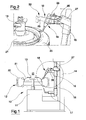
- figure 2 is a detailed view of a tool group of the device of figure 1 in a special operational configuration;
- figures 3, 4 and 5 are schematic views relating to special operating configurations of a tool of the device of the invention;
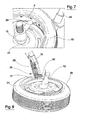
- figures 6 and 7 are detailed views relating to special operating configurations of a second tool of the device of the invention;
- figure 8 is a detailed view of the tool group of figure 2 in a different operational configuration.
- With reference to figure 1 of the drawings, 10 denotes in its entirety a tyre dismounting machine comprising a
wheel support 11, to which awheel 12 is constrained by a self-centring device 13, a positioning of which is automatically obtained according to the diameter of the wheel. - The machine comprises a
column 14 located laterally to thewheel support 11, whichcolumn 14 is provided with aslidable support guide 15 for tool-bearing horizontal arms. In particular, one of thearms 16 is destined to operate in the zone above thewheel support 11, while anotherarm 17 is destined to operate in the zone below thewheel support 11. - As we can see in figure 2, two
different tools arm 16. Thefirst tool 18 is for extracting the upper bead of thetyre 20 from therim 21, while thesecond tool 19 is for mounting the tyre in the run. - The extractor
first tool 18 is composed of acylindrical stem 22, which is provided with acurved end 23 and which is housed, freely rotatable, in asupport seating 24, anchored to an end of apivot 25 arranged internally of thearm 16. Preferably the angle comprised between thecurved end 23 and thecylindrical stem 22 is comprised between 45° and 90°. Thecylindrical stem 22 of thefirst tool 18 is connected at an upper end thereof to acon rod mechanism 26 activated by anactuator cylinder 27 to move between two positions, one of which positions is the arrangement of thecurved end 23 tangentially to thewheel rim 21, as shown in figure 2, while the other position is the arrangement of thecurved end 23 perpendicularly to the wheel rim, in a hooking configuration on the bead 28 of the tyre, as shown in figure 4. - The axis of the
first tool 18 is inclined with respect to the wheel axis; thefirst tool 18 is also not comprised in a plane passing through the wheel axis. This skewed position of the two axes facilitates extraction of the tyre from the rim when thecurved end 23 of thefirst tool 18 has hooked onto the bead 28 of the tyre. - The
mounting tool 19 is composed of alever 29 having a flat section and bearing at an end thereof anappendix 30 which is curved towards an outside of the wheel, theappendix 30 comprising a firstrectangular portion 31 and a secondcircular portion 32, respectively destined to hook the upper bead of the tyre when the upper bead is extracted from the rim, and to push the bead towards the inside of the rim while the tyre is rotated on thewheel support 11. Themounting tool 19 is brought from the rest position, illustrated in figure 2, to the operative position, illustrated in figure 8, and back again by rotations of thesupport sleeve 35 which is rotatable internally of thearm 16. - The lower tool-bearing
arm 17 supports an L-shaped tool 33, which tool faces upwards and an end of which 34 is slightly curved towards the outside of the wheel. Thetool 33 is destined to be translated parallel to the wheel axis, in proximity of therim 21 edge, both for completing the dismounting of thetyre from the rim, pushing the lower bead of the tyre above the rim, as illustrated in figure 6, and for remounting the lower part of the tyre in the rim, by hooking the lower bead with thecurved end 34 and dragging the bead downwards while thewheel 12 is rotated on thewheel support 11, as illustrated in figure 7. - The functioning of the pneumatic dismounting and mounting device is as follows.
- After the
wheel 12 has been positioned on thewheel support 11 by automatic centring obtained following the input data provided to themachine 10 according to the diameter of the wheel, and after the bead-breaking operation has been carried out, the upper tool-bearingarm 16 is translated into a position in which the extractorfirst tool 18 can be arranged in the configuration of figure 2 where, as can be seen, thecurved end 23 of the tool is tangential to the edge of therim 21, in a position from which by advancing the tool in the direction of the axis thereof the end can enter between the tyre and the rim in the way illustrated in figure 3. Advancing thetool 18 in the above-mentioned direction is achieved by combining the vertical translation movement of thearm 16 and the horizontal translation movement of thewheel support 11, which also sets the wheel in rotating motion. - At the moment when the
first tool 18 is in the position of figure 3, theactuator 27 acting on thecon rod mechanism 26 is commanded to rotate the stem of thefirst tool 18 until thecurved end 23 thereof is brought into the hooking position on the tyre as illustrated in figure 4. At this point the upper bead 28 is extracted from the rim by together actuating thearm 16 and thewheel support 11 in order to obtain, for the curved end, determined trajectories, which among other things guarantee the hooking up between thefirst tool 18 and the tyre during the whole course of the extraction, from the position of figure 4 to the position of figure 5. - At the end of the extraction of the upper bead 28 of the tyre from the
rim 21, the upper tool-bearingarm 16 is returned to the rest position after which thelower arm 17 is commanded to translate upwards so that thetool 33 supported thereon extracts the lower bead of the tyre from the rim. - The mounting operation of the
tyre 20 in therim 21 is done first using the L-shaped tool, to whichend 34 of which the lower bead of the tyre is hooked, as illustrated in figure 7. The tyre is made to rotate on thewheel support 11 and drawn downwards by thetool 33, so that the whole lower bead can be inserted in the rim. After this the upper bead 28 of thetyre 20 is also inserted, using themounting tool 19, positioned as in figure 8. Therectangular portion 31 of themounting tool 19 is hooked to the bead 28 of the tyre, which tyre is rotated in the direction indicated by the arrows F. Following this rotation the bead 28 is automatically inserted in the rim thanks to the action exerted thereon by thecircular portion 32 of thetool 19. - The advantage and structural characteristics, as well as the operational advantages of the device of the invention, are evident from the above description, and it is also obvious that these characteristics and advantages are maintained even where modifications and variations are applied to the machine.
- For example the reliability of the hooking operation of the bead by the
first tool 18 remains the same, thanks to the shape and arrangement of thefirst tool 18 with respect to the wheel; and this remains the same even if some variations are brought to the device relating to the overall sizes or details of any of its components. The innovative advantages deriving from the automatic aspect both of the tyre dismounting operation and the mounting operation also remain the same. - Obviously the shape and dimensions of the tool-bearing
arms - The actuating means used for the various actuator groups could also change according to the applications, though the speed aspect and the precision aspect would be conserved.
- The lever constituting the mounting
tool 19 can obviously have a different section from the rectangular section of the illustrated embodiment.
Claims (7)
- A device for mounting and dismounting tyres of wheels positioned on a wheel support of a tyre changing machine, in which tool groups are supported and actuated by tool-bearing arms (16, 17) arranged above and below the wheel support (11) and being vertically translatable with respect to lateral columns (14) for anchoring and support, characterised in that at least one of the tool groups comprises at least an extractor first tool (18) comprising a cylindrical stem (22) having a curved end (23) which cylindrical stem (22) is housed rotatably in a support seating (24) constrained to one of the tool-bearing arms (16, 17) and is actuated in order to introduce the curve end (23) between a rim (21) and a tyre (20), another end of the stem (22) being connected to an actuator (27) for rotating the stem (22).
- The device of claim 1, characterised in that a rotation of the stem (22) is made over an angle which is sufficient to bring the curved edge (23), once inserted between rim and tyre, into a hooking position with a bead (28) of the tyre (20).
- The device of claim 2, characterised in that an axis of rotation of the stem (22) of the extractor first tool (18) is arranged in a skewed position with respect to an axis of rotation of the wheel (12).
- The device of any one of the preceding claims, characterised in that at least one of the tool groups comprises a second tool (19) comprising a lever (29) with an appendix (30) at an end thereof, which appendix (30) is curved towards an outside of the wheel, and which is provided with a rectangular first portion (31) destined to engage with the bead (28) during a mounting operation, and a circular second portion (32) which is coplanar to the rectangular first portion (31) and destined to push the bead (28) towards an inside area of the rim (21) while the tyre (20) is rotated by the wheel support (11).
- The device of any one of the preceding claims, characterised in that the wheel support (11) is provided with a self-centring blocking device (13) of the rim (21), a positioning thereof being automatically obtained according to a diameter of the wheel (12), the tool-bearing arms (16, 17) arranged below and above the wheel support (11) being radially aligned with respect to the self-centring device (13).
- The device of any one of the preceding claims, characterised in that the tool-bearing arm (17) arranged below the wheel support (11) supports an upwards-directed L-shaped tool (33) having an upper end (34) which is slightly curved towards an outside of the wheel, the L-shaped tool (33) being translated parallel to an axis of the wheel (21) in proximity of an edge of the rim (21).
- The device of claim 6, characterised in that the L-shaped tool (33) is used to push the tyre (20) upwards while rotating, so that a dismounting operation thereof from the rim (21) is completed after extraction of the upper bead (28), the L-shaped tool (33) being used in a mounting operation of a lower bead of the tyre (20) internally of the rim (21), by hooking the lower bead with the curved upper end (34) and displacing the lower bead downwards while the wheel support (11) is rotated.
Applications Claiming Priority (2)
| Application Number | Priority Date | Filing Date | Title |
|---|---|---|---|
| IT000084A ITMO20030084A1 (en) | 2003-03-21 | 2003-03-21 | DEVICE FOR MONITORING AND DISASSEMBLING TIRES OF WHEELS POSITIONED ON WHEEL HOLDER TABLES OF TIRE CHANGERS. |
| ITMO20030084 | 2003-03-21 |
Publications (3)
| Publication Number | Publication Date |
|---|---|
| EP1459913A2 true EP1459913A2 (en) | 2004-09-22 |
| EP1459913A3 EP1459913A3 (en) | 2004-11-10 |
| EP1459913B1 EP1459913B1 (en) | 2007-07-04 |
Family
ID=27677389
Family Applications (1)
| Application Number | Title | Priority Date | Filing Date |
|---|---|---|---|
| EP04004342A Expired - Fee Related EP1459913B1 (en) | 2003-03-21 | 2004-02-26 | A device for mounting and dismounting tyres |
Country Status (5)
| Country | Link |
|---|---|
| US (1) | US7108036B2 (en) |
| EP (1) | EP1459913B1 (en) |
| JP (1) | JP4299167B2 (en) |
| DE (1) | DE602004007314T2 (en) |
| IT (1) | ITMO20030084A1 (en) |
Cited By (4)
| Publication number | Priority date | Publication date | Assignee | Title |
|---|---|---|---|---|
| EP1743782A1 (en) * | 2005-07-11 | 2007-01-17 | CORGHI S.p.A. | Method and device for dismounting run-flat tyres |
| ITBO20120189A1 (en) * | 2012-04-11 | 2013-10-12 | Corghi Spa | DISASSEMBLY TOOL FOR A TIRE CHANGER MACHINE AND TIRE DISASSEMBLER |
| ITBO20130523A1 (en) * | 2013-09-25 | 2015-03-26 | Corghi Spa | TOOL FOR DISASSEMBLY OF A TIRE AND TIRE DISMANTLING MACHINE |
| EP2905153A1 (en) * | 2014-02-07 | 2015-08-12 | SICAM S.r.l. | Tyre-changing machine |
Families Citing this family (12)
| Publication number | Priority date | Publication date | Assignee | Title |
|---|---|---|---|---|
| DE202004006462U1 (en) * | 2004-04-23 | 2005-09-01 | Jungheinrich Aktiengesellschaft | Conveyor with attachment |
| ITVR20050037A1 (en) * | 2005-03-23 | 2006-09-24 | Butler Eng & Marketing | TOOL FOR AUTOMATIC ASSEMBLY / DISASSEMBLY OF A TIRE ON / FROM A RIM |
| US7343955B2 (en) | 2005-12-28 | 2008-03-18 | Hennessy Industries, Inc. | Tire changing machine |
| US7438109B2 (en) | 2005-12-30 | 2008-10-21 | Hennessy Industries, Inc. | Tire changer |
| ITMO20060398A1 (en) * | 2006-12-04 | 2008-06-05 | Gino Ferrari | APPARATUS FOR REMOVAL TIRE MACHINES |
| ES2356039T3 (en) | 2008-04-17 | 2011-04-04 | Snap-On Equipment Srl A Unico Socio | PROCEDURE AND APPLIANCE FOR MOUNTING AND DISASSEMBLING A MOTOR VEHICLE TIRE. |
| US8333228B1 (en) | 2008-10-15 | 2012-12-18 | Hennessy Industries, Inc. | Tire changer with attached inflation cage |
| IT1402585B1 (en) * | 2010-10-22 | 2013-09-13 | Maioli | TANK MACHINE. |
| CA2944344C (en) | 2014-04-03 | 2019-04-16 | Bridgestone Bandag, Llc | Automatic system and method for mounting and dismounting tire casing on expandable rim hub in retreading operations |
| ES2616537T3 (en) | 2014-07-03 | 2017-06-13 | Corghi S.P.A. | Machine and method for mounting and disassembling a tire |
| JP6335369B1 (en) * | 2017-06-20 | 2018-05-30 | 伊藤 明 | Tire removal method and apparatus |
| US20210237507A1 (en) * | 2020-02-03 | 2021-08-05 | GM Global Technology Operations LLC | Method of manufacturing a road wheel with galvanic corrosion isolation |
Citations (4)
| Publication number | Priority date | Publication date | Assignee | Title |
|---|---|---|---|---|
| US3844328A (en) * | 1972-09-07 | 1974-10-29 | W Lund | Tire changer for spoked wheels |
| EP1052120A1 (en) * | 1999-05-14 | 2000-11-15 | GIULIANO S.r.l. | Multipurpose station for mounting and removing conventional and special tires |
| EP1177920A2 (en) * | 2000-08-03 | 2002-02-06 | CORGHI S.p.A. | Automatic tyre removal and mounting device, and tyre removal machines equipped therewith |
| US20020162633A1 (en) * | 2000-11-09 | 2002-11-07 | Yoshio Mimura | Apparatus for detaching a tire from a vehicle wheel and the same method |
Family Cites Families (1)
| Publication number | Priority date | Publication date | Assignee | Title |
|---|---|---|---|---|
| US3086578A (en) * | 1960-07-28 | 1963-04-23 | Fmc Corp | Tire changing apparatus |
-
2003
- 2003-03-21 IT IT000084A patent/ITMO20030084A1/en unknown
-
2004
- 2004-02-26 EP EP04004342A patent/EP1459913B1/en not_active Expired - Fee Related
- 2004-02-26 DE DE602004007314T patent/DE602004007314T2/en not_active Expired - Lifetime
- 2004-03-03 US US10/790,710 patent/US7108036B2/en active Active
- 2004-03-19 JP JP2004080530A patent/JP4299167B2/en not_active Expired - Fee Related
Patent Citations (4)
| Publication number | Priority date | Publication date | Assignee | Title |
|---|---|---|---|---|
| US3844328A (en) * | 1972-09-07 | 1974-10-29 | W Lund | Tire changer for spoked wheels |
| EP1052120A1 (en) * | 1999-05-14 | 2000-11-15 | GIULIANO S.r.l. | Multipurpose station for mounting and removing conventional and special tires |
| EP1177920A2 (en) * | 2000-08-03 | 2002-02-06 | CORGHI S.p.A. | Automatic tyre removal and mounting device, and tyre removal machines equipped therewith |
| US20020162633A1 (en) * | 2000-11-09 | 2002-11-07 | Yoshio Mimura | Apparatus for detaching a tire from a vehicle wheel and the same method |
Cited By (10)
| Publication number | Priority date | Publication date | Assignee | Title |
|---|---|---|---|---|
| EP1743782A1 (en) * | 2005-07-11 | 2007-01-17 | CORGHI S.p.A. | Method and device for dismounting run-flat tyres |
| US7395849B2 (en) | 2005-07-11 | 2008-07-08 | Corghi S.P.A. | Method and device for dismounting self-supporting tyres |
| ITBO20120189A1 (en) * | 2012-04-11 | 2013-10-12 | Corghi Spa | DISASSEMBLY TOOL FOR A TIRE CHANGER MACHINE AND TIRE DISASSEMBLER |
| EP2650147A1 (en) | 2012-04-11 | 2013-10-16 | CORGHI S.p.A. | A tyre removal tool for a tyre removing machine and a tyre removing machine |
| CN103373186A (en) * | 2012-04-11 | 2013-10-30 | 科希股份有限公司 | A tyre removal tool for a tyre removing machine and a tyre removing machine |
| US9067467B2 (en) | 2012-04-11 | 2015-06-30 | Corghi S.P.A. | Tyre removal tool for a tyre removing machine and a tyre removing machine |
| CN103373186B (en) * | 2012-04-11 | 2016-12-28 | 科希股份有限公司 | Tire removal tool and the tire dismounting machine of machine is removed for tire |
| ITBO20130523A1 (en) * | 2013-09-25 | 2015-03-26 | Corghi Spa | TOOL FOR DISASSEMBLY OF A TIRE AND TIRE DISMANTLING MACHINE |
| EP2905153A1 (en) * | 2014-02-07 | 2015-08-12 | SICAM S.r.l. | Tyre-changing machine |
| CN104827836A (en) * | 2014-02-07 | 2015-08-12 | 西卡姆有限公司 | Tyre-changing machine |
Also Published As
| Publication number | Publication date |
|---|---|
| DE602004007314T2 (en) | 2008-03-13 |
| ITMO20030084A1 (en) | 2004-09-22 |
| US7108036B2 (en) | 2006-09-19 |
| ITMO20030084A0 (en) | 2003-03-21 |
| JP2004284580A (en) | 2004-10-14 |
| DE602004007314D1 (en) | 2007-08-16 |
| US20040182520A1 (en) | 2004-09-23 |
| EP1459913B1 (en) | 2007-07-04 |
| JP4299167B2 (en) | 2009-07-22 |
| EP1459913A3 (en) | 2004-11-10 |
Similar Documents
| Publication | Publication Date | Title |
|---|---|---|
| EP1459913B1 (en) | A device for mounting and dismounting tyres | |
| JP5069830B2 (en) | Automatic tire removal and attachment device and tire removal machine equipped with the device | |
| US6527032B2 (en) | Automatic bead release device for tire removal machines, and tire removal machines equipped therewith | |
| JP5651351B2 (en) | Vehicle wheel tire attachment / detachment machine | |
| EP1398184B1 (en) | Simplified automatic tyre demounting device, and tyre removal machines equipped therewith | |
| EP1314584B1 (en) | Bead releasing and removing head for a tire-fitting machine | |
| EP1743782B1 (en) | Method and device for dismounting run-flat tyres | |
| EP2629992B1 (en) | A tyre demounting machine | |
| EP1897709B1 (en) | Machine for fitting and removing vehicle tyres | |
| EP1897708A1 (en) | Machine for fitting and removing tyres and wheel rims for vehicles | |
| EP2253487B1 (en) | Tool for a tyre demounting machine | |
| CN105415988A (en) | Machine For Removing And Fitting Wheel Tyres For Vehicles | |
| US7946016B2 (en) | Method and machine for removing a tyre fitted with a rigid inner run-flat ring | |
| EP1724129B1 (en) | A device for debeading tyres from wheels positioned on a turntable of a tyre-removing machine | |
| EP2756969B1 (en) | Machine for removing/ fitting a tyre from/ on the rim of a vehicle vehicles | |
| EP1844960A1 (en) | Machine for assembling and disassembling a tyre fitted with a rigid inner run-flat ring | |
| CN214727975U (en) | Auxiliary device for pressing tire | |
| CN113147283A (en) | Auxiliary device for pressing tire |
Legal Events
| Date | Code | Title | Description |
|---|---|---|---|
| PUAI | Public reference made under article 153(3) epc to a published international application that has entered the european phase |
Free format text: ORIGINAL CODE: 0009012 |
|
| AK | Designated contracting states |
Kind code of ref document: A2 Designated state(s): AT BE BG CH CY CZ DE DK EE ES FI FR GB GR HU IE IT LI LU MC NL PT RO SE SI SK TR |
|
| AX | Request for extension of the european patent |
Extension state: AL LT LV MK |
|
| PUAL | Search report despatched |
Free format text: ORIGINAL CODE: 0009013 |
|
| AK | Designated contracting states |
Kind code of ref document: A3 Designated state(s): AT BE BG CH CY CZ DE DK EE ES FI FR GB GR HU IE IT LI LU MC NL PT RO SE SI SK TR |
|
| AX | Request for extension of the european patent |
Extension state: AL LT LV MK |
|
| 17P | Request for examination filed |
Effective date: 20050412 |
|
| AKX | Designation fees paid |
Designated state(s): DE FR |
|
| GRAP | Despatch of communication of intention to grant a patent |
Free format text: ORIGINAL CODE: EPIDOSNIGR1 |
|
| GRAS | Grant fee paid |
Free format text: ORIGINAL CODE: EPIDOSNIGR3 |
|
| GRAA | (expected) grant |
Free format text: ORIGINAL CODE: 0009210 |
|
| AK | Designated contracting states |
Kind code of ref document: B1 Designated state(s): DE FR |
|
| REF | Corresponds to: |
Ref document number: 602004007314 Country of ref document: DE Date of ref document: 20070816 Kind code of ref document: P |
|
| ET | Fr: translation filed | ||
| PLBE | No opposition filed within time limit |
Free format text: ORIGINAL CODE: 0009261 |
|
| STAA | Information on the status of an ep patent application or granted ep patent |
Free format text: STATUS: NO OPPOSITION FILED WITHIN TIME LIMIT |
|
| 26N | No opposition filed |
Effective date: 20080407 |
|
| REG | Reference to a national code |
Ref country code: FR Ref legal event code: PLFP Year of fee payment: 13 |
|
| PGFP | Annual fee paid to national office [announced via postgrant information from national office to epo] |
Ref country code: FR Payment date: 20160229 Year of fee payment: 13 |
|
| REG | Reference to a national code |
Ref country code: FR Ref legal event code: ST Effective date: 20171031 |
|
| PG25 | Lapsed in a contracting state [announced via postgrant information from national office to epo] |
Ref country code: FR Free format text: LAPSE BECAUSE OF NON-PAYMENT OF DUE FEES Effective date: 20170228 |
|
| PGFP | Annual fee paid to national office [announced via postgrant information from national office to epo] |
Ref country code: DE Payment date: 20180430 Year of fee payment: 15 |
|
| REG | Reference to a national code |
Ref country code: DE Ref legal event code: R119 Ref document number: 602004007314 Country of ref document: DE |
|
| PG25 | Lapsed in a contracting state [announced via postgrant information from national office to epo] |
Ref country code: DE Free format text: LAPSE BECAUSE OF NON-PAYMENT OF DUE FEES Effective date: 20190903 |