EP2995476A1 - Operating head for removing and fitting wheel tyres for vehicles - Google Patents
Operating head for removing and fitting wheel tyres for vehicles Download PDFInfo
- Publication number
- EP2995476A1 EP2995476A1 EP15184099.8A EP15184099A EP2995476A1 EP 2995476 A1 EP2995476 A1 EP 2995476A1 EP 15184099 A EP15184099 A EP 15184099A EP 2995476 A1 EP2995476 A1 EP 2995476A1
- Authority
- EP
- European Patent Office
- Prior art keywords
- operating head
- tool
- fact
- rim
- tyre
- Prior art date
- Legal status (The legal status is an assumption and is not a legal conclusion. Google has not performed a legal analysis and makes no representation as to the accuracy of the status listed.)
- Granted
Links
- 238000001514 detection method Methods 0.000 claims abstract description 7
- 239000011324 bead Substances 0.000 claims description 12
- 238000000605 extraction Methods 0.000 claims description 4
- 210000003414 extremity Anatomy 0.000 description 6
- 210000003141 lower extremity Anatomy 0.000 description 2
- 230000000284 resting effect Effects 0.000 description 2
- 238000004873 anchoring Methods 0.000 description 1
- 238000012423 maintenance Methods 0.000 description 1
- 239000002184 metal Substances 0.000 description 1
- 230000035945 sensitivity Effects 0.000 description 1
Images

Classifications
-
- B—PERFORMING OPERATIONS; TRANSPORTING
- B60—VEHICLES IN GENERAL
- B60C—VEHICLE TYRES; TYRE INFLATION; TYRE CHANGING; CONNECTING VALVES TO INFLATABLE ELASTIC BODIES IN GENERAL; DEVICES OR ARRANGEMENTS RELATED TO TYRES
- B60C25/00—Apparatus or tools adapted for mounting, removing or inspecting tyres
- B60C25/01—Apparatus or tools adapted for mounting, removing or inspecting tyres for removing tyres from or mounting tyres on wheels
- B60C25/05—Machines
- B60C25/0548—Machines equipped with sensing means, e.g. for positioning, measuring or controlling
- B60C25/056—Machines equipped with sensing means, e.g. for positioning, measuring or controlling measuring speed, acceleration or forces
-
- B—PERFORMING OPERATIONS; TRANSPORTING
- B60—VEHICLES IN GENERAL
- B60C—VEHICLE TYRES; TYRE INFLATION; TYRE CHANGING; CONNECTING VALVES TO INFLATABLE ELASTIC BODIES IN GENERAL; DEVICES OR ARRANGEMENTS RELATED TO TYRES
- B60C25/00—Apparatus or tools adapted for mounting, removing or inspecting tyres
- B60C25/01—Apparatus or tools adapted for mounting, removing or inspecting tyres for removing tyres from or mounting tyres on wheels
- B60C25/05—Machines
- B60C25/0548—Machines equipped with sensing means, e.g. for positioning, measuring or controlling
- B60C25/0551—Machines equipped with sensing means, e.g. for positioning, measuring or controlling mechanical
-
- B—PERFORMING OPERATIONS; TRANSPORTING
- B60—VEHICLES IN GENERAL
- B60C—VEHICLE TYRES; TYRE INFLATION; TYRE CHANGING; CONNECTING VALVES TO INFLATABLE ELASTIC BODIES IN GENERAL; DEVICES OR ARRANGEMENTS RELATED TO TYRES
- B60C25/00—Apparatus or tools adapted for mounting, removing or inspecting tyres
- B60C25/01—Apparatus or tools adapted for mounting, removing or inspecting tyres for removing tyres from or mounting tyres on wheels
- B60C25/05—Machines
- B60C25/0563—Tools interacting with the tyre and moved in relation to the tyre during operation
- B60C25/0578—Tools interacting with the tyre and moved in relation to the tyre during operation hooking only
-
- B—PERFORMING OPERATIONS; TRANSPORTING
- B60—VEHICLES IN GENERAL
- B60C—VEHICLE TYRES; TYRE INFLATION; TYRE CHANGING; CONNECTING VALVES TO INFLATABLE ELASTIC BODIES IN GENERAL; DEVICES OR ARRANGEMENTS RELATED TO TYRES
- B60C25/00—Apparatus or tools adapted for mounting, removing or inspecting tyres
- B60C25/01—Apparatus or tools adapted for mounting, removing or inspecting tyres for removing tyres from or mounting tyres on wheels
- B60C25/05—Machines
- B60C25/132—Machines for removing and mounting tyres
- B60C25/135—Machines for removing and mounting tyres having a tyre support or a tool, movable along wheel axis
- B60C25/138—Machines for removing and mounting tyres having a tyre support or a tool, movable along wheel axis with rotary motion of tool or tyre support
Definitions
- the present invention relates to an operating head for removing and fitting wheel tyres for vehicles.
- vehicle wheels generally comprise a metal rim having along its perimeter annular flanges among which the end portions, so-called “beads”, of an elastic tyre are inserted in adhering abutment.
- tyre-changing machines suitable for removing and fitting the tyre from/onto the relative rim to run, e.g., maintenance, repair or replacement jobs.
- tyre-changing machines comprising an operating head having a tool which can be shifted in height and horizontally by the action of respective actuators and usable for fitting and removing the tyre onto/from the rim.
- the tools of known type generally have a lower abutment portion which can be positioned in correspondence of a stretch of the rim edge of a wheel fixed on the machine, in order to allow the tyre removal operations.
- a particular type of known tools has a retractable nail with a curved end part able to grip the tyre bead.
- the nail is movable, due to the action of an actuator commonly mounted on the movable arm, between a bead fastening position, wherein it extends from the operating head to be interposed between the annular flange of the rim and a stretch of the tyre to be removed, and an extraction position of the tyre edge, wherein it is raised to extract the stretch of the bead grasped above the rim annular flange.
- the operator adjusts the position of the operating head with respect to the frame according to the specific dimensions of the wheel, and positions the tool resting on the rim edge.
- the nail is then brought to the fastening position and the end part presses the tyre flank as far as introducing itself between the tyre bead and the relative flange on the rim, so as to position the hooked extremity to retain the tyre bead. Subsequently, the nail is positioned in the extraction position so as to extract a portion of the bead above the rim.
- the positioning of the lower portion of the tool on the rim edge is carried out manually by the operator who, according to his/her sensitivity, adjusts the force applied by the tool on the edge of the rim itself.
- the main aim of the present invention is to provide an operating head for removing and fitting wheel tyres for vehicles which allows to eliminate the risks of damaging the rim caused by an excessive pressure of the tool during the tyre fitting/removal operations.
- Another object of the present invention is to provide an operating head for removing and fitting wheel tyres for vehicles which allows to overcome the mentioned drawbacks of the prior art within the ambit of a simple, rational, easy, effective to use and affordable solution.
- reference number 1 globally indicates an operating head installable on a tyre-changing machine 2 and usable for the fitting and/or removal of a tyre P onto/from the rim C of a wheel R.
- the operating head 1 can be installed on a machine 2 for the removal and fitting of wheel tyres for vehicles of a conventional type.
- the machine 2 may comprise a bearing structure 3, substantially made up of a base 4 resting on the ground and of an upright 5 which rises from the base itself, locking means 6 of a rim C of a wheel R supported by the base B and a tool-carrying arm 7 supported movable vertically and horizontally to the upright 5.
- a bearing structure 3 substantially made up of a base 4 resting on the ground and of an upright 5 which rises from the base itself, locking means 6 of a rim C of a wheel R supported by the base B and a tool-carrying arm 7 supported movable vertically and horizontally to the upright 5.
- the operating head 1 can be fixed to the lower extremity of the tool-carrying arm 7 of the machine 2.
- the operating head 1 comprising at least a fitting/removing tool 8 associable with the tool-carrying arm 7 and having an abutment portion 9 which can be positioned in correspondence ofa stretch of the edge B of the rim C of the wheel R.
- the tool 8 has attachment means 10, the type of one or more threaded elements, able to allow the anchoring of the operating head 1 at the lower extremity of the tool-carrying arm 7.
- the operating head 1 comprises a force measuring device 11 linked together with the tool 8 and having a contact portion 12 arranged substantially in correspondence of the abutment portion 9 and able to be placed in contact with the edge B of the rim C to detect the force applied on the edge B along a respective direction of detection.
- the force measuring device 11 comprises a force sensor 13.
- the force sensor 13 is constituted by a load cell of the type, e.g., of a shear load cell or the like.
- the force measuring device 11 also comprises at least a feeler element 14 having the contact portion 12 and associated with the force sensor 13.
- the feeler element 14 has a substantially elongated conformation, extends along a direction of detection and has an extremity associated with the force sensor 13 and an opposite extremity having the contact portion 12.
- the force sensor 13 is anchored to the body of tool 8 by means of at least one holding bracket 15. A different fastening of the force sensor 13 to the tool 8 cannot however be ruled out.
- the contact portion 12 is made up of a portion of the tool 8 and the force sensor 13 is integrated in the tool itself.
- the operating head 1 may comprise a plurality of force sensors 13 having respective contact portions 12 able to engage in correspondence of respective portions of the edge B of the rim C, in order to detect the forces applied on the edge B along different directions of detection.
- the machine 2 has movement means for moving the operating head 1 along a vertical direction, not shown in the illustrations, operatively connected to the force sensor 13 and able to vary the pressure of the contact portion 12 of the operating head 1 on the edge B of the rim C depending on the force detected by the force sensor 13.
- said movement means are able to vary the position of the operating head 1 also during the removal or fitting operations of the tyre, depending on the force variations detected by the force sensor 13.
- the operating head 1 comprises a movable nail 16 supported by the tool 8 and having a substantially hook-shaped free extremity.
- the movable nail 16 is able to be moved by the action of actuator means 17 between a fastening position, wherein it extends from the tool 8 beyond the abutment portion 9 to be inserted between the edge B of the rim C and the tyre P and to position the free extremity below the bead of the tyre P, and an extraction position, wherein the free extremity is arranged in correspondence of the abutment portion 9 to extract the bead of the tyre P above the edge B of rim C.
Abstract
Description
- The present invention relates to an operating head for removing and fitting wheel tyres for vehicles.
- It is well known that vehicle wheels generally comprise a metal rim having along its perimeter annular flanges among which the end portions, so-called "beads", of an elastic tyre are inserted in adhering abutment.
- The use is currently known of machines, so-called "tyre-changing machines", suitable for removing and fitting the tyre from/onto the relative rim to run, e.g., maintenance, repair or replacement jobs.
- Different types of tyre-changing machines are known, in particular, comprising an operating head having a tool which can be shifted in height and horizontally by the action of respective actuators and usable for fitting and removing the tyre onto/from the rim.
- The tools of known type generally have a lower abutment portion which can be positioned in correspondence ofa stretch of the rim edge of a wheel fixed on the machine, in order to allow the tyre removal operations.
- In addition, a particular type of known tools has a retractable nail with a curved end part able to grip the tyre bead.
- In particular, the nail is movable, due to the action of an actuator commonly mounted on the movable arm, between a bead fastening position, wherein it extends from the operating head to be interposed between the annular flange of the rim and a stretch of the tyre to be removed, and an extraction position of the tyre edge, wherein it is raised to extract the stretch of the bead grasped above the rim annular flange.
- During use, the operator adjusts the position of the operating head with respect to the frame according to the specific dimensions of the wheel, and positions the tool resting on the rim edge.
- The nail is then brought to the fastening position and the end part presses the tyre flank as far as introducing itself between the tyre bead and the relative flange on the rim, so as to position the hooked extremity to retain the tyre bead. Subsequently, the nail is positioned in the extraction position so as to extract a portion of the bead above the rim.
- The rotation of the rim then allows the coming out of the entyre bead from the respective flange.
- The operating heads and tools of the known type generally have, however, some drawbacks.
- In particular, the positioning of the lower portion of the tool on the rim edge is carried out manually by the operator who, according to his/her sensitivity, adjusts the force applied by the tool on the edge of the rim itself.
- This implies therefore the need to use qualified personnel and, in any case, can result in damages to the rim during the positioning of the tool, or else subsequently, during the tyre removal job.
- The main aim of the present invention is to provide an operating head for removing and fitting wheel tyres for vehicles which allows to eliminate the risks of damaging the rim caused by an excessive pressure of the tool during the tyre fitting/removal operations.
- Another object of the present invention is to provide an operating head for removing and fitting wheel tyres for vehicles which allows to overcome the mentioned drawbacks of the prior art within the ambit of a simple, rational, easy, effective to use and affordable solution.
- The above mentioned objects are achieved by this operating head for removing and fitting wheel tyres for vehicles according to claim 1.
- Other characteristics and advantages of the present invention will become better evident from the description of a preferred, but not exclusive embodiment of an operating head for removing and fitting wheel tyres for vehicles, illustrated by way of an indicative but non-limiting example, in the accompanying drawings in which:
-
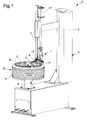
Figure 1 is a view of the operating head according to the invention installed on a tyre-changing machine; -
Figure 2 is an axonometric view of the operating head according to the invention; -
Figure 3 is a side view illustrating the positioning of the operating head according to the invention in correspondence ofa stretch of the rim edge of a wheel. - With particular reference to such figures, reference number 1 globally indicates an operating head installable on a tyre-changing
machine 2 and usable for the fitting and/or removal of a tyre P onto/from the rim C of a wheel R. - As illustrated by way of example in
Figure 1 , the operating head 1 can be installed on amachine 2 for the removal and fitting of wheel tyres for vehicles of a conventional type. - For example, the
machine 2 may comprise a bearing structure 3, substantially made up of a base 4 resting on the ground and of an upright 5 which rises from the base itself, locking means 6 of a rim C of a wheel R supported by the base B and a tool-carrying arm 7 supported movable vertically and horizontally to the upright 5. - In particular, the operating head 1 can be fixed to the lower extremity of the tool-carrying arm 7 of the
machine 2. - The operating head 1 comprising at least a fitting/removing
tool 8 associable with the tool-carrying arm 7 and having anabutment portion 9 which can be positioned in correspondence ofa stretch of the edge B of the rim C of the wheel R. - In particular, the
tool 8 has attachment means 10, the type of one or more threaded elements, able to allow the anchoring of the operating head 1 at the lower extremity of the tool-carrying arm 7. - Advantageously, the operating head 1 comprises a
force measuring device 11 linked together with thetool 8 and having acontact portion 12 arranged substantially in correspondence of theabutment portion 9 and able to be placed in contact with the edge B of the rim C to detect the force applied on the edge B along a respective direction of detection. - In particular, the
force measuring device 11 comprises aforce sensor 13. Preferably, theforce sensor 13 is constituted by a load cell of the type, e.g., of a shear load cell or the like. - Preferably, the
force measuring device 11 also comprises at least afeeler element 14 having thecontact portion 12 and associated with theforce sensor 13. - In particular, the
feeler element 14 has a substantially elongated conformation, extends along a direction of detection and has an extremity associated with theforce sensor 13 and an opposite extremity having thecontact portion 12. - With reference to the particular embodiment illustrated in the figures, the
force sensor 13 is anchored to the body oftool 8 by means of at least oneholding bracket 15. A different fastening of theforce sensor 13 to thetool 8 cannot however be ruled out. - Different embodiments of the
force measuring device 11 cannot also be ruled out in which, e.g., thecontact portion 12 is made up of a portion of thetool 8 and theforce sensor 13 is integrated in the tool itself. - Advantageously, the operating head 1 may comprise a plurality of
force sensors 13 havingrespective contact portions 12 able to engage in correspondence of respective portions of the edge B of the rim C, in order to detect the forces applied on the edge B along different directions of detection. - Furthermore, the
machine 2 has movement means for moving the operating head 1 along a vertical direction, not shown in the illustrations, operatively connected to theforce sensor 13 and able to vary the pressure of thecontact portion 12 of the operating head 1 on the edge B of the rim C depending on the force detected by theforce sensor 13. - Advantageously, said movement means are able to vary the position of the operating head 1 also during the removal or fitting operations of the tyre, depending on the force variations detected by the
force sensor 13. - In this way it is possible to avoid any damage to the rim due to, e.g., variations in the inclination or the conformation of the surface of the edge B of the rim C. Still with reference to the particular embodiment illustrated in the figures, the operating head 1 comprises a
movable nail 16 supported by thetool 8 and having a substantially hook-shaped free extremity. - The
movable nail 16 is able to be moved by the action of actuator means 17 between a fastening position, wherein it extends from thetool 8 beyond theabutment portion 9 to be inserted between the edge B of the rim C and the tyre P and to position the free extremity below the bead of the tyre P, and an extraction position, wherein the free extremity is arranged in correspondence of theabutment portion 9 to extract the bead of the tyre P above the edge B of rim C. - It has in practice been ascertained how the described invention achieves the proposed objects.
- In particular the fact is underlined that the presence of the force measuring device allows to eliminate the risks of damaging the rim caused by an excessive pressure by the tool during the tyre fitting/removal operations.
Claims (12)
- Operating head (1) for removing and fitting wheel tyres for vehicles, comprising at least a tool (8) for the fitting and/or removal of a tyre, associable with a tool-carrying arm (7) of a tyre-changing machine (2) and having at least an abutment portion (9) which can be positioned in correspondence of a stretch of the edge (B) of the rim (C) of a wheel (R) fixed on said tyre-changing machine (2), characterized by the fact that it comprises at least a force measuring device (11) linked together with said tool (8) and having a contact portion (12) arranged substantially in correspondence of said abutment portion (9) and able to be placed in contact with said edge (B) of the rim (C) to detect the force applied on said edge (B) along at least a direction of detection.
- Operating head (1) according to claim 1, characterized by the fact that said force measuring device (11) comprises at least a force sensor (13).
- Operating head (1) according to claim 2, characterized by the fact that said force sensor (13) comprises at least a load cell (13).
- Operating head (1) according to one or more of the preceding claims, characterized by the fact that said force measuring device (11) comprises at least a feeler element (14) having said contact portion (12) and associated with said force sensor (13).
- Operating head (1) according to claim 4, characterized by the fact that said feeler element (14) has a substantially elongated conformation, extends substantially along said direction of detection and has an extremity associated with said force sensor (13) and an opposite extremity having said contact portion (12).
- Operating head (1) according to one or more of the preceding claims, characterized by the fact that said force measuring device (11) is anchored to said tool (8) by means of at least a holding bracket (15).
- Operating head (1) according to one or more of claims 1 to 3, characterized by the fact that said contact portion (12) is made of at least a portion of said tool (8).
- Operating head (1) according to one or more of the preceding claims, characterized by the fact that it comprises a plurality of said force measuring devices (11) having respective contact portions (12) able to be placed in contact with respective portions of said edge (B) of the rim (C) to detect the forces applied on said edge (B) along different directions of detection.
- Operating head (1) according to one or more of the preceding claims, characterized by the fact that said tool (8) comprises attachment means (10) associable with said tool-carrying arm (7) of the tyre-changing machine (2),
- Operating head (1) according to one or more of the preceding claims, characterized by the fact that it comprises at least a movable nail (16) having a substantially hook-shaped free extremity, associated with said tool (8) and movable between a fastening position, wherein said movable nail (16) extends beyond said abutment portion (9) to be inserted between said edge (B) of the rim (C) and the tyre (P) of said wheel (R) and to position said free extremity below the bead of said tyre (P), and an extraction position, wherein said free extremity is arranged in correspondence of said abutment portion (9) to extract said bead of the tyre (P) above said edge (B) of the rim (C).
- Machine (2) for removing and fitting wheel tyres for vehicles, comprising at least a bearing structure (3), locking means (6) of a rim (C) of a wheel (R) for vehicles and at least a tool-carrying arm (7) associated movable with said bearing structure (3), characterized by the fact that said tool-carrying arm (7) has at least an operating head (1) according to one or more of the preceding claims.
- Machine (2) according to claim 11, characterized by the fact that it comprises movement means for moving said operating head (1) operatively connected to said force measuring device (11) and able to vary the pressure of said contact portion (12) of the operating head (1) on said edge (B) of the rim (C) depending on the force detected by said force measuring device (11).
Applications Claiming Priority (1)
| Application Number | Priority Date | Filing Date | Title |
|---|---|---|---|
| ITMO20140256 | 2014-09-12 |
Publications (2)
| Publication Number | Publication Date |
|---|---|
| EP2995476A1 true EP2995476A1 (en) | 2016-03-16 |
| EP2995476B1 EP2995476B1 (en) | 2017-11-08 |
Family
ID=51904092
Family Applications (1)
| Application Number | Title | Priority Date | Filing Date |
|---|---|---|---|
| EP15184099.8A Active EP2995476B1 (en) | 2014-09-12 | 2015-09-07 | Operating head for removing and fitting wheel tyres for vehicles |
Country Status (3)
| Country | Link |
|---|---|
| US (1) | US20160075194A1 (en) |
| EP (1) | EP2995476B1 (en) |
| CN (1) | CN105415989B (en) |
Cited By (1)
| Publication number | Priority date | Publication date | Assignee | Title |
|---|---|---|---|---|
| EP4011652A1 (en) | 2020-12-10 | 2022-06-15 | NEXION S.p.A. | Working head for a tyre changing apparatus |
Families Citing this family (1)
| Publication number | Priority date | Publication date | Assignee | Title |
|---|---|---|---|---|
| ES2725481T3 (en) * | 2016-10-18 | 2019-09-24 | Nexion Spa | Tire change machine |
Citations (3)
| Publication number | Priority date | Publication date | Assignee | Title |
|---|---|---|---|---|
| US6125904A (en) * | 1998-06-01 | 2000-10-03 | Aim Automotive Integrated Manufacturing, Inc. | Robotic apparatus and method for assembling a tire to a rim |
| EP2319715A1 (en) * | 2009-11-05 | 2011-05-11 | CORGHI S.p.A. | An apparatus and method for mounting and removing tyres on and from respective wheel rims |
| US8770254B1 (en) * | 2008-07-17 | 2014-07-08 | Hunter Engineering Company | Tire changer with rotational position and tracking control |
Family Cites Families (9)
| Publication number | Priority date | Publication date | Assignee | Title |
|---|---|---|---|---|
| ITVR20040055A1 (en) * | 2004-04-09 | 2004-07-09 | Butler Eng & Marketing | AUTOMATIC FEELER FOR TIRE MOUNTING MACHINES |
| ITVR20050043A1 (en) * | 2005-04-07 | 2006-10-08 | Butler Eng & Marketing | TIRE ASSEMBLY MACHINE WITH TIPPING ASSEMBLY / DISASSEMBLY TOOL |
| US8387675B1 (en) * | 2009-09-09 | 2013-03-05 | Hunter Engineering Company | Tire changing machine with automated tire bead pressing devices, controls and methods |
| US8613303B1 (en) * | 2008-07-17 | 2013-12-24 | Hunter Engineering Company | Tire changing machine with force detection and control methods |
| JP5403952B2 (en) * | 2008-06-11 | 2014-01-29 | 株式会社神戸製鋼所 | Tire testing machine and tire testing method |
| US8250915B1 (en) * | 2008-07-03 | 2012-08-28 | Hunter Engineering Company | Tire changer with actuated load roller |
| EP2361791B1 (en) * | 2010-02-17 | 2013-06-05 | Snap-on Equipment Srl a unico socio | Tyre changer and a method of measuring force variations acting between a peripheral surface of a wheel/tyre assembly and a roller |
| ITMO20110316A1 (en) * | 2011-12-02 | 2013-06-03 | Giuliano Group Spa | OPERATING HEAD FOR DISASSEMBLY AND ASSEMBLY OF WHEEL TIRES FOR VEHICLES |
| ITMO20120191A1 (en) * | 2012-07-31 | 2014-02-01 | Sicam Srl | TIRE CHANGER MACHINE FOR THE ASSEMBLY AND DISASSEMBLY OF VEHICLE WHEELS |
-
2015
- 2015-09-07 EP EP15184099.8A patent/EP2995476B1/en active Active
- 2015-09-09 US US14/848,433 patent/US20160075194A1/en not_active Abandoned
- 2015-09-14 CN CN201510583821.7A patent/CN105415989B/en active Active
Patent Citations (3)
| Publication number | Priority date | Publication date | Assignee | Title |
|---|---|---|---|---|
| US6125904A (en) * | 1998-06-01 | 2000-10-03 | Aim Automotive Integrated Manufacturing, Inc. | Robotic apparatus and method for assembling a tire to a rim |
| US8770254B1 (en) * | 2008-07-17 | 2014-07-08 | Hunter Engineering Company | Tire changer with rotational position and tracking control |
| EP2319715A1 (en) * | 2009-11-05 | 2011-05-11 | CORGHI S.p.A. | An apparatus and method for mounting and removing tyres on and from respective wheel rims |
Cited By (1)
| Publication number | Priority date | Publication date | Assignee | Title |
|---|---|---|---|---|
| EP4011652A1 (en) | 2020-12-10 | 2022-06-15 | NEXION S.p.A. | Working head for a tyre changing apparatus |
Also Published As
| Publication number | Publication date |
|---|---|
| EP2995476B1 (en) | 2017-11-08 |
| US20160075194A1 (en) | 2016-03-17 |
| CN105415989B (en) | 2017-10-13 |
| CN105415989A (en) | 2016-03-23 |
Similar Documents
| Publication | Publication Date | Title |
|---|---|---|
| US10071607B2 (en) | Apparatus and method for mounting and removing tyres on and from respective wheel rims | |
| US8276641B2 (en) | Tire-changing machine for fitting and removing vehicle wheels | |
| US8291958B2 (en) | Machine for fitting and removing the tires of vehicles | |
| US9834046B2 (en) | Tyre-changing machine | |
| EP2996889B1 (en) | Tyre-changing machine for trucks | |
| EP3075577B1 (en) | Machine for fitting and removing wheel tyres for vehicles | |
| EP2338705B1 (en) | Bead breaking unit for tyre changing machines | |
| US8464775B2 (en) | Tool for tire uninstalling and installing machines | |
| EP2995478B1 (en) | Machine for removing and fitting wheel tyres for vehicles | |
| US8826962B2 (en) | Upgraded bead breaking unit for tyre changing machines or the like | |
| EP2995476B1 (en) | Operating head for removing and fitting wheel tyres for vehicles | |
| EP2905154A1 (en) | Tyre-changing machine | |
| JP5401081B2 (en) | Vehicle wheel tire mounting / removal device | |
| EP3293020A1 (en) | Tyre changing machine | |
| WO2010137557A3 (en) | Auxiliary tool for changing tyres | |
| EP2756969B1 (en) | Machine for removing/ fitting a tyre from/ on the rim of a vehicle vehicles | |
| EP3741591A1 (en) | Tyre-changing machine, particularly for large wheels | |
| US8424584B2 (en) | Unit for beading tires in tire changing machines or the like | |
| EP1852273A1 (en) | Auxiliary device for workshop machines suitable for lifting wheels for vehicles, particularly for tyre-changing machines or the like | |
| US20150224834A1 (en) | Tyre-changing machine | |
| EP2803970A1 (en) | Appliance and method for bending tests on tyre-changing machines | |
| ITBO20090728A1 (en) | EQUIPMENT AND METHOD FOR THE ASSEMBLY AND DISASSEMBLY OF TIRES ON AND FROM CORRESPONDING CIRCLES. |
Legal Events
| Date | Code | Title | Description |
|---|---|---|---|
| PUAI | Public reference made under article 153(3) epc to a published international application that has entered the european phase |
Free format text: ORIGINAL CODE: 0009012 |
|
| AK | Designated contracting states |
Kind code of ref document: A1 Designated state(s): AL AT BE BG CH CY CZ DE DK EE ES FI FR GB GR HR HU IE IS IT LI LT LU LV MC MK MT NL NO PL PT RO RS SE SI SK SM TR |
|
| AX | Request for extension of the european patent |
Extension state: BA ME |
|
| RBV | Designated contracting states (corrected) |
Designated state(s): AL AT BE BG CH CY CZ DE DK EE ES FI FR GB GR HR HU IE IS IT LI LT LU LV MC MK MT NL NO PL PT RO RS SE SI SK SM TR |
|
| 17P | Request for examination filed |
Effective date: 20160916 |
|
| GRAP | Despatch of communication of intention to grant a patent |
Free format text: ORIGINAL CODE: EPIDOSNIGR1 |
|
| INTG | Intention to grant announced |
Effective date: 20170511 |
|
| GRAS | Grant fee paid |
Free format text: ORIGINAL CODE: EPIDOSNIGR3 |
|
| GRAA | (expected) grant |
Free format text: ORIGINAL CODE: 0009210 |
|
| AK | Designated contracting states |
Kind code of ref document: B1 Designated state(s): AL AT BE BG CH CY CZ DE DK EE ES FI FR GB GR HR HU IE IS IT LI LT LU LV MC MK MT NL NO PL PT RO RS SE SI SK SM TR |
|
| REG | Reference to a national code |
Ref country code: GB Ref legal event code: FG4D |
|
| REG | Reference to a national code |
Ref country code: CH Ref legal event code: EP Ref country code: AT Ref legal event code: REF Ref document number: 943783 Country of ref document: AT Kind code of ref document: T Effective date: 20171115 |
|
| REG | Reference to a national code |
Ref country code: IE Ref legal event code: FG4D |
|
| REG | Reference to a national code |
Ref country code: DE Ref legal event code: R096 Ref document number: 602015005832 Country of ref document: DE |
|
| REG | Reference to a national code |
Ref country code: NL Ref legal event code: MP Effective date: 20171108 |
|
| REG | Reference to a national code |
Ref country code: LT Ref legal event code: MG4D |
|
| REG | Reference to a national code |
Ref country code: AT Ref legal event code: MK05 Ref document number: 943783 Country of ref document: AT Kind code of ref document: T Effective date: 20171108 |
|
| PG25 | Lapsed in a contracting state [announced via postgrant information from national office to epo] |
Ref country code: LT Free format text: LAPSE BECAUSE OF FAILURE TO SUBMIT A TRANSLATION OF THE DESCRIPTION OR TO PAY THE FEE WITHIN THE PRESCRIBED TIME-LIMIT Effective date: 20171108 Ref country code: NL Free format text: LAPSE BECAUSE OF FAILURE TO SUBMIT A TRANSLATION OF THE DESCRIPTION OR TO PAY THE FEE WITHIN THE PRESCRIBED TIME-LIMIT Effective date: 20171108 Ref country code: SE Free format text: LAPSE BECAUSE OF FAILURE TO SUBMIT A TRANSLATION OF THE DESCRIPTION OR TO PAY THE FEE WITHIN THE PRESCRIBED TIME-LIMIT Effective date: 20171108 Ref country code: NO Free format text: LAPSE BECAUSE OF FAILURE TO SUBMIT A TRANSLATION OF THE DESCRIPTION OR TO PAY THE FEE WITHIN THE PRESCRIBED TIME-LIMIT Effective date: 20180208 Ref country code: ES Free format text: LAPSE BECAUSE OF FAILURE TO SUBMIT A TRANSLATION OF THE DESCRIPTION OR TO PAY THE FEE WITHIN THE PRESCRIBED TIME-LIMIT Effective date: 20171108 Ref country code: FI Free format text: LAPSE BECAUSE OF FAILURE TO SUBMIT A TRANSLATION OF THE DESCRIPTION OR TO PAY THE FEE WITHIN THE PRESCRIBED TIME-LIMIT Effective date: 20171108 |
|
| PG25 | Lapsed in a contracting state [announced via postgrant information from national office to epo] |
Ref country code: IS Free format text: LAPSE BECAUSE OF FAILURE TO SUBMIT A TRANSLATION OF THE DESCRIPTION OR TO PAY THE FEE WITHIN THE PRESCRIBED TIME-LIMIT Effective date: 20180308 Ref country code: AT Free format text: LAPSE BECAUSE OF FAILURE TO SUBMIT A TRANSLATION OF THE DESCRIPTION OR TO PAY THE FEE WITHIN THE PRESCRIBED TIME-LIMIT Effective date: 20171108 Ref country code: RS Free format text: LAPSE BECAUSE OF FAILURE TO SUBMIT A TRANSLATION OF THE DESCRIPTION OR TO PAY THE FEE WITHIN THE PRESCRIBED TIME-LIMIT Effective date: 20171108 Ref country code: LV Free format text: LAPSE BECAUSE OF FAILURE TO SUBMIT A TRANSLATION OF THE DESCRIPTION OR TO PAY THE FEE WITHIN THE PRESCRIBED TIME-LIMIT Effective date: 20171108 Ref country code: BG Free format text: LAPSE BECAUSE OF FAILURE TO SUBMIT A TRANSLATION OF THE DESCRIPTION OR TO PAY THE FEE WITHIN THE PRESCRIBED TIME-LIMIT Effective date: 20180208 Ref country code: GR Free format text: LAPSE BECAUSE OF FAILURE TO SUBMIT A TRANSLATION OF THE DESCRIPTION OR TO PAY THE FEE WITHIN THE PRESCRIBED TIME-LIMIT Effective date: 20180209 Ref country code: HR Free format text: LAPSE BECAUSE OF FAILURE TO SUBMIT A TRANSLATION OF THE DESCRIPTION OR TO PAY THE FEE WITHIN THE PRESCRIBED TIME-LIMIT Effective date: 20171108 |
|
| PG25 | Lapsed in a contracting state [announced via postgrant information from national office to epo] |
Ref country code: EE Free format text: LAPSE BECAUSE OF FAILURE TO SUBMIT A TRANSLATION OF THE DESCRIPTION OR TO PAY THE FEE WITHIN THE PRESCRIBED TIME-LIMIT Effective date: 20171108 Ref country code: CY Free format text: LAPSE BECAUSE OF FAILURE TO SUBMIT A TRANSLATION OF THE DESCRIPTION OR TO PAY THE FEE WITHIN THE PRESCRIBED TIME-LIMIT Effective date: 20171108 Ref country code: DK Free format text: LAPSE BECAUSE OF FAILURE TO SUBMIT A TRANSLATION OF THE DESCRIPTION OR TO PAY THE FEE WITHIN THE PRESCRIBED TIME-LIMIT Effective date: 20171108 Ref country code: CZ Free format text: LAPSE BECAUSE OF FAILURE TO SUBMIT A TRANSLATION OF THE DESCRIPTION OR TO PAY THE FEE WITHIN THE PRESCRIBED TIME-LIMIT Effective date: 20171108 Ref country code: SK Free format text: LAPSE BECAUSE OF FAILURE TO SUBMIT A TRANSLATION OF THE DESCRIPTION OR TO PAY THE FEE WITHIN THE PRESCRIBED TIME-LIMIT Effective date: 20171108 |
|
| REG | Reference to a national code |
Ref country code: DE Ref legal event code: R097 Ref document number: 602015005832 Country of ref document: DE |
|
| PG25 | Lapsed in a contracting state [announced via postgrant information from national office to epo] |
Ref country code: SM Free format text: LAPSE BECAUSE OF FAILURE TO SUBMIT A TRANSLATION OF THE DESCRIPTION OR TO PAY THE FEE WITHIN THE PRESCRIBED TIME-LIMIT Effective date: 20171108 Ref country code: RO Free format text: LAPSE BECAUSE OF FAILURE TO SUBMIT A TRANSLATION OF THE DESCRIPTION OR TO PAY THE FEE WITHIN THE PRESCRIBED TIME-LIMIT Effective date: 20171108 Ref country code: PL Free format text: LAPSE BECAUSE OF FAILURE TO SUBMIT A TRANSLATION OF THE DESCRIPTION OR TO PAY THE FEE WITHIN THE PRESCRIBED TIME-LIMIT Effective date: 20171108 |
|
| PLBE | No opposition filed within time limit |
Free format text: ORIGINAL CODE: 0009261 |
|
| STAA | Information on the status of an ep patent application or granted ep patent |
Free format text: STATUS: NO OPPOSITION FILED WITHIN TIME LIMIT |
|
| REG | Reference to a national code |
Ref country code: FR Ref legal event code: PLFP Year of fee payment: 4 |
|
| 26N | No opposition filed |
Effective date: 20180809 |
|
| PG25 | Lapsed in a contracting state [announced via postgrant information from national office to epo] |
Ref country code: SI Free format text: LAPSE BECAUSE OF FAILURE TO SUBMIT A TRANSLATION OF THE DESCRIPTION OR TO PAY THE FEE WITHIN THE PRESCRIBED TIME-LIMIT Effective date: 20171108 |
|
| PG25 | Lapsed in a contracting state [announced via postgrant information from national office to epo] |
Ref country code: MC Free format text: LAPSE BECAUSE OF FAILURE TO SUBMIT A TRANSLATION OF THE DESCRIPTION OR TO PAY THE FEE WITHIN THE PRESCRIBED TIME-LIMIT Effective date: 20171108 |
|
| REG | Reference to a national code |
Ref country code: CH Ref legal event code: PL |
|
| REG | Reference to a national code |
Ref country code: BE Ref legal event code: MM Effective date: 20180930 |
|
| REG | Reference to a national code |
Ref country code: IE Ref legal event code: MM4A |
|
| PG25 | Lapsed in a contracting state [announced via postgrant information from national office to epo] |
Ref country code: LU Free format text: LAPSE BECAUSE OF NON-PAYMENT OF DUE FEES Effective date: 20180907 |
|
| PG25 | Lapsed in a contracting state [announced via postgrant information from national office to epo] |
Ref country code: IE Free format text: LAPSE BECAUSE OF NON-PAYMENT OF DUE FEES Effective date: 20180907 |
|
| PG25 | Lapsed in a contracting state [announced via postgrant information from national office to epo] |
Ref country code: LI Free format text: LAPSE BECAUSE OF NON-PAYMENT OF DUE FEES Effective date: 20180930 Ref country code: BE Free format text: LAPSE BECAUSE OF NON-PAYMENT OF DUE FEES Effective date: 20180930 Ref country code: CH Free format text: LAPSE BECAUSE OF NON-PAYMENT OF DUE FEES Effective date: 20180930 |
|
| PG25 | Lapsed in a contracting state [announced via postgrant information from national office to epo] |
Ref country code: MT Free format text: LAPSE BECAUSE OF NON-PAYMENT OF DUE FEES Effective date: 20180907 |
|
| PG25 | Lapsed in a contracting state [announced via postgrant information from national office to epo] |
Ref country code: TR Free format text: LAPSE BECAUSE OF FAILURE TO SUBMIT A TRANSLATION OF THE DESCRIPTION OR TO PAY THE FEE WITHIN THE PRESCRIBED TIME-LIMIT Effective date: 20171108 |
|
| PG25 | Lapsed in a contracting state [announced via postgrant information from national office to epo] |
Ref country code: PT Free format text: LAPSE BECAUSE OF FAILURE TO SUBMIT A TRANSLATION OF THE DESCRIPTION OR TO PAY THE FEE WITHIN THE PRESCRIBED TIME-LIMIT Effective date: 20171108 |
|
| PG25 | Lapsed in a contracting state [announced via postgrant information from national office to epo] |
Ref country code: HU Free format text: LAPSE BECAUSE OF FAILURE TO SUBMIT A TRANSLATION OF THE DESCRIPTION OR TO PAY THE FEE WITHIN THE PRESCRIBED TIME-LIMIT; INVALID AB INITIO Effective date: 20150907 Ref country code: MK Free format text: LAPSE BECAUSE OF NON-PAYMENT OF DUE FEES Effective date: 20171108 |
|
| PG25 | Lapsed in a contracting state [announced via postgrant information from national office to epo] |
Ref country code: AL Free format text: LAPSE BECAUSE OF FAILURE TO SUBMIT A TRANSLATION OF THE DESCRIPTION OR TO PAY THE FEE WITHIN THE PRESCRIBED TIME-LIMIT Effective date: 20171108 |
|
| PGFP | Annual fee paid to national office [announced via postgrant information from national office to epo] |
Ref country code: GB Payment date: 20220927 Year of fee payment: 8 Ref country code: DE Payment date: 20220928 Year of fee payment: 8 |
|
| PGFP | Annual fee paid to national office [announced via postgrant information from national office to epo] |
Ref country code: FR Payment date: 20220926 Year of fee payment: 8 |
|
| PGFP | Annual fee paid to national office [announced via postgrant information from national office to epo] |
Ref country code: IT Payment date: 20220922 Year of fee payment: 8 |