EP2181834A2 - Rotorblattgurt - Google Patents
Rotorblattgurt Download PDFInfo
- Publication number
- EP2181834A2 EP2181834A2 EP09173751A EP09173751A EP2181834A2 EP 2181834 A2 EP2181834 A2 EP 2181834A2 EP 09173751 A EP09173751 A EP 09173751A EP 09173751 A EP09173751 A EP 09173751A EP 2181834 A2 EP2181834 A2 EP 2181834A2
- Authority
- EP
- European Patent Office
- Prior art keywords
- resin
- fiber material
- flow aid
- vacuum
- fiber
- Prior art date
- Legal status (The legal status is an assumption and is not a legal conclusion. Google has not performed a legal analysis and makes no representation as to the accuracy of the status listed.)
- Granted
Links
Images


Classifications
-
- B—PERFORMING OPERATIONS; TRANSPORTING
- B29—WORKING OF PLASTICS; WORKING OF SUBSTANCES IN A PLASTIC STATE IN GENERAL
- B29C—SHAPING OR JOINING OF PLASTICS; SHAPING OF MATERIAL IN A PLASTIC STATE, NOT OTHERWISE PROVIDED FOR; AFTER-TREATMENT OF THE SHAPED PRODUCTS, e.g. REPAIRING
- B29C70/00—Shaping composites, i.e. plastics material comprising reinforcements, fillers or preformed parts, e.g. inserts
- B29C70/04—Shaping composites, i.e. plastics material comprising reinforcements, fillers or preformed parts, e.g. inserts comprising reinforcements only, e.g. self-reinforcing plastics
- B29C70/28—Shaping operations therefor
- B29C70/40—Shaping or impregnating by compression not applied
- B29C70/42—Shaping or impregnating by compression not applied for producing articles of definite length, i.e. discrete articles
- B29C70/44—Shaping or impregnating by compression not applied for producing articles of definite length, i.e. discrete articles using isostatic pressure, e.g. pressure difference-moulding, vacuum bag-moulding, autoclave-moulding or expanding rubber-moulding
- B29C70/443—Shaping or impregnating by compression not applied for producing articles of definite length, i.e. discrete articles using isostatic pressure, e.g. pressure difference-moulding, vacuum bag-moulding, autoclave-moulding or expanding rubber-moulding and impregnating by vacuum or injection
-
- B—PERFORMING OPERATIONS; TRANSPORTING
- B29—WORKING OF PLASTICS; WORKING OF SUBSTANCES IN A PLASTIC STATE IN GENERAL
- B29C—SHAPING OR JOINING OF PLASTICS; SHAPING OF MATERIAL IN A PLASTIC STATE, NOT OTHERWISE PROVIDED FOR; AFTER-TREATMENT OF THE SHAPED PRODUCTS, e.g. REPAIRING
- B29C70/00—Shaping composites, i.e. plastics material comprising reinforcements, fillers or preformed parts, e.g. inserts
- B29C70/04—Shaping composites, i.e. plastics material comprising reinforcements, fillers or preformed parts, e.g. inserts comprising reinforcements only, e.g. self-reinforcing plastics
- B29C70/28—Shaping operations therefor
- B29C70/54—Component parts, details or accessories; Auxiliary operations, e.g. feeding or storage of prepregs or SMC after impregnation or during ageing
- B29C70/546—Measures for feeding or distributing the matrix material in the reinforcing structure
- B29C70/547—Measures for feeding or distributing the matrix material in the reinforcing structure using channels or porous distribution layers incorporated in or associated with the product
-
- B—PERFORMING OPERATIONS; TRANSPORTING
- B29—WORKING OF PLASTICS; WORKING OF SUBSTANCES IN A PLASTIC STATE IN GENERAL
- B29L—INDEXING SCHEME ASSOCIATED WITH SUBCLASS B29C, RELATING TO PARTICULAR ARTICLES
- B29L2031/00—Other particular articles
- B29L2031/08—Blades for rotors, stators, fans, turbines or the like, e.g. screw propellers
- B29L2031/082—Blades, e.g. for helicopters
-
- B—PERFORMING OPERATIONS; TRANSPORTING
- B29—WORKING OF PLASTICS; WORKING OF SUBSTANCES IN A PLASTIC STATE IN GENERAL
- B29L—INDEXING SCHEME ASSOCIATED WITH SUBCLASS B29C, RELATING TO PARTICULAR ARTICLES
- B29L2031/00—Other particular articles
- B29L2031/08—Blades for rotors, stators, fans, turbines or the like, e.g. screw propellers
- B29L2031/082—Blades, e.g. for helicopters
- B29L2031/085—Wind turbine blades
-
- Y—GENERAL TAGGING OF NEW TECHNOLOGICAL DEVELOPMENTS; GENERAL TAGGING OF CROSS-SECTIONAL TECHNOLOGIES SPANNING OVER SEVERAL SECTIONS OF THE IPC; TECHNICAL SUBJECTS COVERED BY FORMER USPC CROSS-REFERENCE ART COLLECTIONS [XRACs] AND DIGESTS
- Y02—TECHNOLOGIES OR APPLICATIONS FOR MITIGATION OR ADAPTATION AGAINST CLIMATE CHANGE
- Y02E—REDUCTION OF GREENHOUSE GAS [GHG] EMISSIONS, RELATED TO ENERGY GENERATION, TRANSMISSION OR DISTRIBUTION
- Y02E10/00—Energy generation through renewable energy sources
- Y02E10/70—Wind energy
- Y02E10/72—Wind turbines with rotation axis in wind direction
-
- Y—GENERAL TAGGING OF NEW TECHNOLOGICAL DEVELOPMENTS; GENERAL TAGGING OF CROSS-SECTIONAL TECHNOLOGIES SPANNING OVER SEVERAL SECTIONS OF THE IPC; TECHNICAL SUBJECTS COVERED BY FORMER USPC CROSS-REFERENCE ART COLLECTIONS [XRACs] AND DIGESTS
- Y02—TECHNOLOGIES OR APPLICATIONS FOR MITIGATION OR ADAPTATION AGAINST CLIMATE CHANGE
- Y02P—CLIMATE CHANGE MITIGATION TECHNOLOGIES IN THE PRODUCTION OR PROCESSING OF GOODS
- Y02P70/00—Climate change mitigation technologies in the production process for final industrial or consumer products
- Y02P70/50—Manufacturing or production processes characterised by the final manufactured product
Definitions
- the invention relates to a method for producing a fiber-reinforced belt of a rotor blade of a wind turbine from a, preferably dry, fiber material.
- rotor blades of wind turbines have a shell, the shell having pairs of oppositely disposed straps, wherein webs are provided between the straps, so that the profile cross-section of the shells is stiffened against bending in the direction of impact.
- the straps consist of longitudinally fiber-reinforced plastics.
- the very light shell of such rotor blades has only a low inherent rigidity and is therefore reinforced by the laminated belts, which run over the essential length of the rotor blade and are formed with fibers running in the longitudinal direction for receiving such tensile and compressive forces.
- a rotor blade bends at each point preferably in the direction perpendicular to its chord, ie the line extending in a transverse to the longitudinal extent of the rotor blade cross-sectional plane of the rounded blade nose to the thin expiring rear end.
- the main straps of the rotor blade are arranged symmetrically opposite to the chord and supported with formed as longitudinal walls webs between these straps. They thus form a stiffened support profile tube high bending stiffness in the direction transverse to the chord of the blade.
- secondary girths can also be arranged in the profile nose and / or the trailing edge of the profile.
- Bending stiffness in the direction of impact is essential for rotor blades. This avoids, among other things, that a rotor blade can strike at high load against the tower of the wind turbine. Furthermore, it must be achieved that the bending stiffness of the rotor blade is so high that the natural frequency of the rotor blade, which depends substantially proportionally on the stiffness and inversely proportional to the mass, is not excited at rotational speeds of the rotor occurring during operation.
- rotor blades usually have straps with glass fiber reinforcement or carbon fiber reinforcement.
- the glass fiber reinforcement is inexpensive, but has low stiffness and high weight compared to carbon fiber reinforcement.
- the fiber reinforced belts of rotor blades are manufactured using resin infusion techniques.
- DE 100 13 409 C1 a method for the production of fiber-reinforced plastic components from dry fiber composite semifinished by means of an injection method for injection of matrix material.
- DE 602 16 108 C2 a method of forming fiber reinforced plastic structures.
- WO-A-2007/038930 a process for producing a fiber-reinforced product using the resin infusion process (RTM, Resin Transfer Molding).
- the object of the present invention is to provide a method for producing a belt of a rotor blade or a belt, wherein the finished manufactured belt to be produced in a simple manner and the belt should have defined edges.
- the invention is based on the idea that there is no contact between the resin gate on the upper side of the fiber material, which is preferably formed from continuous fibers (rovings) or unidirectional layers, and the distribution medium formed as flow aid underneath the fiber material, so that the fiber material over the lower side Flow aid is infused from below, wherein the flow rate of the resin after dispensing down in the direction of the flow aid is so high that the discharged resin flows down to the flow aid and does not come directly to the side adjacent the discharge point of the resin vacuum suction points.
- the resin gate on the upper side of the fiber material, which is preferably formed from continuous fibers (rovings) or unidirectional layers, and the distribution medium formed as flow aid underneath the fiber material, so that the fiber material over the lower side Flow aid is infused from below, wherein the flow rate of the resin after dispensing down in the direction of the flow aid is so high that the discharged resin flows down to the flow aid and does not come directly to the side adjacent the discharge point of the resin vacuum suction points.
- the arrangement is geometrically designed for this purpose so that the flow resistance through the fiber material for flow aid is significantly lower than to the laterally arranged suction points, e.g. in which the lateral distance of the suction points to the gate point is selected to be greater than or the distance between the gate point and flow aid. This ensures that the path of the resin from the gate point down through the fiber material is formed. Subsequently, the resin taken up in the flow aid becomes long and wide, i. outwardly guided, wherein due to the vacuum formed in the interior of the distributed resin soaks the fiber material from bottom to top.
- the resin is down faster towards the edges than at the top, ensuring that the bottom belt layers of the fiber material are injected across the entire width before the resin reaches the vacuum point.
- the resin thus initially spreads relatively quickly through the lower fluid over the entire width and then penetrates the reinforcing fibers consisting of belt material from bottom to top, whereby the edge or regions of the fiber material in the outer regions or smooth edge regions are soaked by the resin ,
- the fibrous material is preferably covered by a gas and air permeable, preferably microporous or semipermeable, membrane permitting gas and air to permeate freely through the membrane, and simultaneously the resin is retained by the membrane and remains in the fiber material.
- a great advantage consists in a very simple design of the form, which has neither resin channels nor vacuum channels or must have.
- the resin at the Harzanguss or Harzfangusstician on the side facing away from the flow aid the upper side of the fiber material directly into the dry fiber material, ie without the use of distribution aids or without the use of flow aids at the top of the fiber material, given so that on the input side or
- the further process steps for the production of the method such as Providing a negative pressure for the impregnation of the fiber material with resin, curing, etc. take place in per se known manner.
- the application of the fiber material with negative pressure or with a vacuum takes place before the injection of the resin.
- the vacuum is applied or withdrawn via at least one semipermeable membrane in or on the cover in the interior.
- a fiber-reinforced belt is produced in a mold with defined mold edges, wherein the produced belt has defined edges due to the process according to the invention, since resin is also distributed or flows via the lower distribution medium or the lower flow aid into the edge regions of the fiber material.
- the previous manufacturing processes of belts of rotor blades straps were produced, which had undefined edges after production or where the belt had to be separately wired and trimmed. That the Beschalung, i.d.R. made of wood, sawed off.
- a shuttering and trimming of the belt is not required because the finished belt is removed from the belt shape or the recess after curing and then directly, i. is inserted into the rotor blade shell without further processing steps.
- the resin is added via one or more channels formed in the fibrous material, so that via the or, in particular vertical, channels, the resin is passed to the lower side flow aid. This will also ensures that the resin is first added quickly over the downwardly directed channels to the lower distribution medium or flow medium or the lower flow aid, so that then the resin is distributed over the entire width of the lower flow aid.
- the method is characterized in that the resin is distributed by means of the lower-side flow aid to the side, so that the edge or regions of the fiber material are soaked by the resin.
- suction points in the cover resin is added via a resin gate on and / or in the fiber material.
- the resin is delivered through the Harzanguss on the top.
- a further method step is characterized in that resin is introduced via a resin gate onto and / or into the fiber material in addition to at least one suction point spaced from the resin gate and preferably formed with a respective semipermeable membrane on the same side of the resin gate. or in the fiber material given resin flows under the fiber material flow aid with applied vacuum and then subsequently distributed in the direction of at least one suction point, so that the fiber material is impregnated in the region between Harzanguss and the at least one suction point of the resin.
- the belt produced has straight edges at the edges, because of the shape, which is preferably rectangular in cross-section. which are impregnated by the resin during the manufacturing process due to the lower side flow aid.
- a tear-off fabric and / or a perforated film is additionally formed underneath the tear-off fabric between the lower flow aid and the fibrous belt material so that the distribution medium or the lower-side flow aid is removed after removal of the manufactured belt, whereby the flow aid does not remain in the belt.
- the lower belt layers are infused over the entire width by means of the underside, resin-soaked flow aid before the resin wets the membrane or membranes arranged on the upper side at the suction point in the upper-side cover, whereby the injection of the fiber material is stopped.
- a vacuum flow or a vacuum aid which forms a uniform vacuum in the interior of the sealed recess of the mold in which the fiber material is arranged, and a favorable vacuum distribution is provided during the entire process duration under applied negative pressure.
- Figures 1 and 2 show schematically views in the direction of the rotor axis or across a wind turbine with a towered on a ground tower at the top of a rotatable nacelle carries a rotating about a substantially horizontal axis rotor, which consists of three rotor blades 1.
- the length of the rotor blades 1 is typically between 40 m to 60 m.
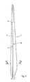
- FIG. 3 and 4 show the internal structure of a rotor blade 1 with a relatively thin shell 2, which is usually made of glass fiber reinforced plastic and on the inside, namely in the direction of the rotor axis of rotation front and rear surfaces each carry a laminated belt 3a, 3b.
- the shell 2 may be formed as a sandwich construction.
- the straps 3a and 3b are formed in the embodiment with substantially identical cross-section. Instead of each of the straps 3a, 3b, as shown in the embodiment, a plurality of parallel straps may be provided in a narrower training.
- Fig. 4 shows, webs 4 are provided between two straps 3 a and 3 b, which are formed as over the length of the belt continuous, stiffened, flat plates. With the straps 3a and 3b and the webs 4 results in a direction perpendicular to the plane of the Fig. 3 , ie perpendicular to the in Fig. 4 illustrated chord 20 rigid profile.
- the straps 3a, 3b extend in the longitudinal direction of the sheet.
- each of the straps 3a, 3b made of fiber-reinforced plastic with in the longitudinal direction of the belt, ie formed unidirectional reinforcing fibers.
- the straps 3a, 3b are made of glass fibers and / or carbon fibers.
- the straps shown 3a, 3b have a much greater width than height.
- the belt has a width of about 60 centimeters and a height in the range of about 5 centimeters.
- the straps 3a, 3b begin as far as possible inside the rotor hub and run to simplify the production of constant width over the top of the rotor blade.
- the adjustment of the belt cross-section of each occurring, male forces takes place by changing the height. In general, the belt cross section, ie the height, from the inside out.
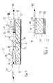
- Fig. 5 shows a schematic view of a device or arrangement for producing a belt of a rotor blade 1 of a wind turbine.
- the device has a mold 10, which has a trough-like depression 11.
- the recess 11 is preferably rectangular in cross-section, wherein the recess 11 is formed by vertical walls 12 and a horizontal bottom 13.
- the floor over the length of the belt has a twist of about 10 ° to 15 ° and is curved.
- a flow aid 14 is designed or arranged over the entire width of the recess or of the bottom 13.
- a Harzanguss 16 is arranged in the middle.
- the recess 11 and the fibers 15 are covered by a cover 17, wherein the cover 17 has seals 18 at their edges, which thereby close the formed interior 19 airtight.
- two membranes 21 are arranged above the fibers 15 in the edge region of the depression 11, a gap 22 being formed between the membranes 21 and the cover 17, each being connected to a vacuum source or vacuum pump via a vacuum connection 24 are so that a vacuum in both the space 22 and in the interior 19 below the cover 17 is formed.
- Resin is applied to the fibers 15 via the resin gate 16 with the delivered resin flowing to the flow aid 14 at the bottom of the fibers 15.
- the resin at the resin gate 16 becomes immediately, i. without interposition or without the use of a distribution medium or the like between the resin gate 16 and the fibers 15 at the top in the fibers 15 entered.
- the absorbed resin is guided laterally outwards to the edges and distributed.
- the space 19 enclosed by the cover 17 is vacuumed so that the air in the inner space 17 is passed through the semipermeable membranes 21 while the resin is retained and wets the membrane 21, stopping the injection of the fibers 15 with resin ,
- an air distribution aid 23 is advantageously formed above the membranes in the intermediate space 22, whereby a uniform vacuum is formed in the space bounded by the cover 17.
- the air distribution aid 23 and the flow aid 14 may advantageously consist of the same material economically.
- the resin discharged from the resin gate 16 passes through optional channels 27, which are in Fig. 5 are indicated by dashes, flows to the lower side flow aid 14.
- the channels 27 are formed from a slotted or porous material (eg foam, balsa wood, etc.).
- the resin gate 16 may also be disposed on one side of the upper side and the suction points with the semipermeable membrane 21 on the other side of the upper side of the fiber material 15 so that the resin progress does not proceed from the center across the bottom to the edges but from the one edge done over the bottom to the other edge.
- Fig. 6 is a detail view Fig. 5 an edge region in the neckline shown, from which it appears that under the fibers 15 and between the flow aid 14 and the fibers 15 a tear-off fabric 25 and a perforated film 26 are disposed below the tear-off fabric 25. After curing of the fibers 15 by removal of the tear-off fabric 25 and the other two layers, perforated foil 26 and flow aid 14 are removed from the belt made of the fiber-reinforced material, whereby the weight of the belt is reduced.
- a tear-off fabric 25 can also be arranged over the fibers 15, that is to say on the side of the belt facing the cover 17.
Landscapes
- Chemical & Material Sciences (AREA)
- Engineering & Computer Science (AREA)
- Composite Materials (AREA)
- Mechanical Engineering (AREA)
- Moulding By Coating Moulds (AREA)
- Casting Or Compression Moulding Of Plastics Or The Like (AREA)
- Wind Motors (AREA)
Abstract
Description
- Die Erfindung betrifft ein Verfahren zum Herstellen eines faserverstärkten Gurts eines Rotorblatts einer Windenergieanlage aus einem, vorzugsweise trockenen, Fasermaterial.
- Es ist bekannt, dass Rotorblätter von Windenergieanlagen eine Schale aufweisen, wobei die Schale paarweise gegenüberliegend angeordnete Gurte aufweist, wobei zwischen den Gurten Stege vorgesehen sind, so dass der Profilquerschnitt der Schalen gegen Biegung in Schlagrichtung versteift ist. Insbesondere bestehen die Gurte aus in Längsrichtung faserverstärkten Kunststoffen. Die sehr leichte Schale derartiger Rotorblätter weist nur eine geringe Eigensteifigkeit auf und ist daher durch die anlaminierten Gurte verstärkt, die über die wesentliche Länge des Rotorblatts laufen und mit in Längsrichtung laufenden Fasern für die Aufnahme solcher Zug- und Druckkräfte ausgebildet sind.
- Biegekräfte am Rotorblatt treten insbesondere durch Windbelastung in Schlagrichtung auf, also in Richtung senkrecht zur Umlaufebene des Blattes. Dabei verbiegt sich ein Rotorblatt an jeder Stelle bevorzugt in Richtung senkrecht zu seiner Profilsehne, also der Linie, die in einer quer zur Längserstreckung des Rotorblatts stehenden Querschnittsebene von der verrundeten Blattnase bis zum dünn auslaufenden hinteren Ende verläuft.
- Die Hauptgurte des Rotorblatts sind symmetrisch zur Profilsehne gegenüberliegend angeordnet und mit als längsverlaufende Wände ausgebildeten Stegen zwischen diesen Gurten ausgestützt. Sie bilden somit ein ausgesteiftes Tragprofilrohr hoher Biegesteifigkeit in Richtung quer zur Profilsehne des Rotorblatts. Außerdem können Nebengurte auch in der Profilnase und/oder der Profilhinterkante angeordnet sein.
- Biegesteifigkeit in Schlagrichtung ist für Rotorblätter von wesentlicher Bedeutung. Dadurch wird unter anderem vermieden, dass ein Rotorblatt bei hoher Belastung gegen den Turm der Windenergieanlage schlagen kann. Ferner muss erreicht werden, dass die Biegesteifigkeit des Rotorblatts so hoch ist, dass die Eigenfrequenz des Rotorblatts, die im Wesentlichen proportional von der Steifigkeit und umgekehrt proportional von der Masse abhängt, bei im Betrieb auftretenden Drehzahlen des Rotors nicht angeregt wird.
- Weiterhin ist bekannt, dass Rotorblätter üblicherweise Gurte mit Glasfaserverstärkung oder Kohlenfaserverstärkung aufweisen. Die Glasfaserverstärkung ist kostengünstig, hat jedoch eine geringe Steifigkeit und ein hohes Gewicht im Vergleich zu Kohlenfaserverstärkung.
- Überdies ist im Stand der Technik bekannt, dass die faserverstärkten Gurte von Rotorblättern unter Verwendung von Harz-Infusionsverfahren hergestellt werden.
- Darüber hinaus ist aus
DE 100 13 409 C1 ein Verfahren zur Herstellung von faserverstärkten Kunststoff-Bauteilen aus trockenen Faserverbund-Halbzeugen mittels eines Injektionsverfahrens zur Injektion von Matrixmaterial bekannt. Weiterhin offenbartDE 602 16 108 C2 ein Verfahren zum Bilden von faserverstärkten Kunststoffstrukturen. - Weiterhin offenbart
WO-A-2007/038930 ein Verfahren zum Herstellen eines faserverstärkten Produktes unter Verwendung des Harz-Infusionsverfahrens (RTM, Resin Transfer Molding). - Ausgehend von diesem Stand der Technik besteht die Aufgabe der vorliegenden Erfindung darin, ein Verfahren zur Herstellung eines Gurtes eines Rotorblatts bzw. einen Gurt bereitzustellen, wobei der fertig hergestellte Gurt auf einfache Weise herzustellen sein und der Gurt definierte Ränder haben soll.
- Gelöst wird die Aufgabe durch ein Verfahren zum Herstellen eines faserverstärkten Gurts eines Rotorblatts einer Windenergieanlage aus einem, vorzugsweise trockenen, Fasermaterial, wobei
- das Fasermaterial in einer Vertiefung einer Form auf einer Fließhilfe angeordnet wird oder ist,
- die Vertiefung auf der Oberseite gegen die äußere Umgebung mittels einer Abdeckung abgedichtet wird oder ist, wobei der abgedichtete Innenraum unter Vakuum gesetzt wird oder ist,
- auf der Oberseite des Fasermaterials Harz an wenigstens einer Stelle auf und/oder in das Fasermaterial gegeben wird, so dass das auf und/oder in das Fasermaterial gegebene Harz zur unter dem Fasermaterial angeordneten Fließhilfe bei angelegtem Vakuum im Innenraum fließt.
- Die Erfindung beruht auf dem Gedanken, dass zwischen dem Harzanguss auf der Oberseite des Fasermaterials, das bevorzugterweise aus Endlosfasern (Rovings) oder unidirektionalen Gelegen gebildet wird, und dem als Fließhilfe ausgebildeten Verteilmediums unterhalb des Fasermaterials kein Kontakt besteht, so dass das Fasermaterial über die unterseitige Fließhilfe von unten infundiert wird, wobei die Fließgeschwindigkeit des Harzes nach Abgabe nach unten in Richtung der Fließhilfe derart hoch ist, dass das abgegebene Harz nach unten zur Fließhilfe fließt und nicht direkt zu den seitlich neben der Abgabestelle des Harzes angeordneten Saugstellen für das Vakuum gelangt.
- Die Anordnung wird hierzu geometrisch so ausgebildet, dass der Fließwiderstand durch das Fasermaterial zur Fließhilfe deutlich geringer ist als zu den seitlich angeordneten Saugstellen, z.B. in dem der seitliche Abstand der Saugstellen zum Angusspunkt größer gewählt wird oder ist als der Abstand zwischen Angusspunkt und Fließhilfe. Hierdurch wird gewährleistet, dass der Weg des Harzes vom Angusspunkt nach unten durch das Fasermaterial ausgebildet ist. Anschließend wird das in der Fließhilfe aufgenommene Harz in die Länge und in die Breite, d.h. nach außen, geführt, wobei aufgrund des im Innenraum ausgebildeten Unterdrucks das verteilte Harz das Fasermaterial von unten nach oben durchtränkt.
- Durch das Verteilmedium bzw. die Fließhilfe unter dem Fasermaterial bzw. dem Gurt ist das Harz unten schneller auf dem Weg zu den Rändern als oben, wodurch gewährleistet wird, dass die unteren Gurtlagen des Fasermaterials über die gesamte Breite injiziert werden, bevor das Harz zu der Vakuumstelle gelangt. Das Harz verteilt sich somit zunächst relativ schnell durch das untere Fließmedium über die gesamte Breite und durchdringt anschließend das aus Verstärkungsfasern bestehende Gurtmaterial dann von unten nach oben, wodurch auch der oder die Randbereiche des Fasermaterials in den äußeren Bereichen bzw. glatten Kantenbereichen vom Harz durchtränkt werden. An der Stelle auf der Oberseite des Fasermaterials, an der das Vakuum aus dem Innenraum gezogen wird, ist bevorzugterweise das Fasermaterial von einer gas- und luftdurchlässigen, bevorzugterweise mikroporösen oder semipermeablen, Membran bedeckt, wodurch Gas und Luft ungehindert durch die Membran permeieren, und gleichzeitig das Harz von der Membran zurückgehalten wird und im Fasermaterial verbleibt.
- Ein großer Vorteil besteht in einer sehr einfachen Gestaltung der Form, die weder Harz-Kanäle noch Vakuum-Kanäle aufweist bzw. aufweisen muss. Mittels der einseitig angeordneten Fließhilfe an der Unterseite des Fasermaterials wird das Harz von der Empfangsstelle, an der das vom Harzangusspunkt eingegebene Harz in die Fließhilfe abgegeben wird, nach außen zu den Randbereichen des anfangs noch trockenen Fasermaterials bzw. von der Empfangsstelle weg geleitet, so dass das Harz unter Verwendung der Fließhilfe verteilt wird bzw. ist.
- Überdies wird das Harz am Harzanguss bzw. Harzangusspunkt auf der der Fließhilfe abgewandten, oberen Seite des Fasermaterials direkt in das trockene Fasermaterial, d.h. ohne Verwendung von Verteilhilfen oder ohne Verwendung von Fließhilfen an der Oberseite des Fasermaterial, gegeben, so dass an der Eingabeseite bzw.
- Angusspunkt das Harz aus dem Harzangusspunkt unmittelbar in das Fasermaterial eintritt. Hierdurch entsteht am oberseitigen Harzangusspunkt keine induzierte Verbreiterung des Bereichs des Harzangusses, da das abgegebene Harz nicht verteilt wird, bevor es durch das Fasermaterial zu der unterseitigen Fließhilfe gelangt, da an der Oberseite zwischen dem Harzanguss und dem Fasermaterial keine Verteilhilfen, Verteilmedien oder Verteilschichten oder dergleichen zur Verteilung von Harz an der Oberseite des Fasermaterials bzw. an der Eingabeseite des Harzes vorgesehen sind.
- Außerdem wird bei dem eingangs genannten Verfahren zum Herstellen eines faserverstärkten Gurts eines Rotorblatts einer Windenergieanlage aus einem, vorzugsweise trockenen, Fasermaterial, als eigenständige Lösung oder als vorteilhaften Verfahrensschritt bzw. Weiterbildung vorgeschlagen, dass
- mindestens einseitig eine Fließhilfe an das Fasermaterial angeordnet wird, und
- Harz auf oder in das, vorzugsweise anfangs trockene, Fasermaterial an wenigstens einer oder mehreren Harzeingabestellen, die auf einer oder der von der Fließhilfe abgewandten Seite des Fasermaterials angeordnet sind, gegeben wird.
- Die weiteren Verfahrensschritte zur Herstellung des Verfahrens wie z.B. Bereitstellen eines Unterdrucks für das Durchtränken des Fasermaterials mit Harz, Aushärten etc. erfolgen auf per se bekannte Weise. Das Beaufschlagen des Fasermaterials mit Unterdruck bzw. mit einem Vakuum erfolgt dabei vor der Injektion des Harzes.
- Überdies wird gemäß einer weiteren Ausgestaltung des Verfahrens vorgeschlagen, dass das mit Harz zu versehende bzw. durchtränkende, vorzugsweise (zuerst) trockene, Fasermaterial mit Vakuum mittels von wenigstens einer oder mehreren Vakuum-Saugvorrichtungen, die an einer der Fließhilfe abgewandten Seite des Fasermaterials, vorzugsweise an den Saugstellen, angeordnet sind, beaufschlagt wird.
- Insbesondere wird das Vakuum über wenigstens eine semipermeable Membran in oder an der Abdeckung im Innenraum angelegt bzw. abgezogen.
- Erfindungsgemäß wird dabei ein faserverstärkter Gurt in einer Form mit definierten Formrändern gefertigt, wobei der hergestellte Gurt aufgrund des erfindungsgemäßen Prozesses definierte Ränder aufweist, da auch Harz über das untere Verteilmedium bzw. die untere Fließhilfe in die Randbereiche des Fasermaterials verteilt wird bzw. fließt. Gemäß den bisherigen Herstellungsprozessen von Gurten von Rotorblättern wurden Gurte hergestellt, die nach der Herstellung undefinierte Ränder aufwiesen oder wobei der Gurt gesondert beschalt und besäumt werden musste. D.h. die Beschalung, i.d.R. aus Holz, wurde abgesägt.
- Demgegenüber ist erfindungsgemäß eine Einschalung und Besäumung des Gurtes nicht erforderlich, da der fertige Gurt aus der Gurtform bzw. der Vertiefung nach der Aushärtung entnommen wird und anschließend direkt, d.h. ohne weitere Bearbeitungsschritte in die Rotorblattschale eingelegt wird.
- In einer bevorzugten Ausführungsform wird das Harz über einen oder mehrere in dem Fasermaterial ausgebildete Kanäle gegeben, so dass über den oder die, insbesondere senkrechten, Kanäle das Harz zur unterseitigen Fließhilfe geleitet wird. Hierdurch wird ebenfalls erreicht, dass das Harz zunächst schnell über die nach unten gerichteten Kanäle auf das untere Verteilmedium bzw. Fließmedium oder die untere Fließhilfe gegeben wird, so dass anschließend das Harz über die gesamte Breite der unteren Fließhilfe verteilt wird.
- Darüber hinaus zeichnet sich das Verfahren dadurch aus, dass das Harz mittels der unterseitigen Fließhilfe zur Seite verteilt wird, so dass der oder die Randbereiche des Fasermaterials vom Harz durchtränkt werden.
- Überdies ist es in einer bevorzugten Ausführungsform vorteilhaft, dass zwischen zwei, vorzugsweise mit jeweils semipermeablen Membranen ausgebildeten, Saugstellen in der Abdeckung Harz über einen Harzanguss auf und/oder in das Fasermaterial gegeben wird. Hierbei wird das Harz über den Harzanguss auf der Oberseite abgegeben.
- Ein weiterer Verfahrensschritt zeichnet sich dadurch aus, dass Harz über einen Harzanguss auf und/oder in das Fasermaterial neben wenigstens einer vom Harzanguss beabstandeten, vorzugsweise mit jeweils einer semipermeablen Membran ausgebildeten, Saugstelle auf derselben Seite des Harzangusses gegeben wird, wobei insbesondere das auf und/oder in das Fasermaterial gegebene Harz zur unter dem Fasermaterial angeordneten Fließhilfe bei angelegtem Vakuum fließt und anschließend nachfolgend in Richtung der wenigstens einen Saugstelle verteilt wird, so dass das Fasermaterial im Bereich zwischen Harzanguss und der wenigstens einen Saugstelle vom Harz durchtränkt wird.
- Durch das erfindungsgemäße Verfahren wird erreicht, dass der hergestellte Gurt aufgrund der, bevorzugterweise im Querschnitt rechteckigen, Form definierte gerade Kanten an den Rändern aufweist, die während des Herstellungsprozesses aufgrund der unterseitigen Fließhilfe vom Harz durchtränkt werden. Bevorzugterweise ist dabei zwischen der unteren Fließhilfe und dem faserigen Gurtmaterial zusätzlich ein Abreißgewebe und/oder eine Lochfolie unter dem Abreißgewebe ausgebildet, so dass das Verteilmedium bzw. die unterseitige Fließhilfe nach der Entformung des hergestellten Gurts entfernt wird, wodurch die Fließhilfe nicht im Gurt verbleibt. Erfindungsgemäß werden die unteren Gurtlagen mittels der unterseitigen, mit Harz getränkten Fließhilfe über die gesamte Breite infundiert, bevor das Harz die auf der Oberseite angeordnete Membran bzw. Membranen an der Saugstelle in der oberseitigen Abdeckung benetzt, wodurch die Injektion des Fasermaterials gestoppt wird.
- Bevorzugterweise ist an der Saugstelle in der oberseitigen Abdeckung auf der Vakuumseite der Membran, d.h. auf der dem Fasermaterial abgewandten Seite der Membran ein Vakuumfließ oder eine Vakuumhilfe angeordnet, wodurch sich im Innenraum der abgedichteten Vertiefung der Form, in der das Fasermaterial angeordnet ist, ein gleichmäßiges Vakuum ausbildet und eine günstige Vakuumverteilung während der gesamten Verfahrensdauer bei angelegtem Unterdruck bereitgestellt wird.
- Nachfolgend wird die Erfindung anhand eines Ausführungsbeispiels exemplarisch und ohne Beschränkung des allgemeinen Erfindungsgedankens beschrieben, wobei bezüglich aller im Text nicht näher erläuterten erfindungsgemäßen Einzelheiten ausdrücklich auf die schematischen Zeichnungen verwiesen wird. Es zeigen:
- Fig. 1
- eine schematische Frontansicht auf eine Windenergieanlage,
- Fig. 2
- eine schematische Seitenansicht der Windenergieanlage der
Fig. 1 , - Fig. 3
- eine schematische Schnittdarstellung eines Rotorblatts der Windenergieanlage der
Figuren 1 und 2 im Schnitt der Linie 3-3 inFig. 4 - Fig. 4
- einen Schnitt nach Linie 4-4 in
Fig. 3 ; - Fig. 5
- einen schematischen Querschnitt durch eine Anordnung zum Herstellen eines Rotorblatts und
- Fig. 6
- eine vergrößerte schematische Detailansicht der Anordnung aus
Fig. 5 . - In den folgenden Figuren sind jeweils gleiche oder gleichartige Elemente bzw. entsprechende Teile mit denselben Bezugsziffern versehen, so dass von einer entsprechenden erneuten Vorstellung abgesehen wird.
-
Figuren 1 und 2 zeigen schematisch Ansichten in Richtung der Rotorachse bzw. quer dazu eine Windenergieanlage mit einem auf einem Boden aufgestellten Turm, an dessen Spitze eine drehbare Gondel einen um eine im Wesentlichen waagerechte Achse umlaufenden Rotor trägt, der aus drei Rotorblättern 1 besteht. Im dargestellten Ausführungsbeispiel einer Windenergieanlage im Leistungsbereich einiger Megawatt liegt die Länge der Rotorblätter 1 typischerweise zwischen 40 m bis 60 m. - Die Schnittdarstellung der
Figuren 3 und4 zeigen den inneren Aufbau eines Rotorblatts 1 mit einer relativ dünnen Schale 2, die üblicherweise aus glasfaserverstärktem Kunststoff besteht und die auf der Innenseite, und zwar auf den in Richtung der Rotordrehachse vorn und hinten liegenden Flächen je einen anlaminierten Gurt 3a, 3b trägt. Bevorzugterweise kann die Schale 2 als Sandwich-Konstruktion ausgebildet sein. - Die Gurte 3a und 3b sind im Ausführungsbeispiel mit im Wesentlichen identischem Querschnitt ausgebildet. Anstelle jedes der Gurte 3a, 3b, wie in der Ausführungsform dargestellt, können auch mehrere parallele Gurte in schmalerer Ausbildung vorgesehen sein.
- Wie
Fig. 4 zeigt, sind zwischen zwei Gurten 3a und 3b Stege 4 vorgesehen, die als über die Länge des Gurtes durchgehende, ausgesteifte, flächige Platten ausgebildet sind. Mit den Gurten 3a und 3b und den Stegen 4 ergibt sich ein in Richtung senkrecht zur Zeichnungsebene derFig. 3 , also senkrecht zu der inFig. 4 dargestellten Profilsehne 20 biegesteifes Profil. - Wie
Fig. 3 zeigt, verlaufen die Gurte 3a, 3b in Längsrichtung des Blattes. In ganzer Länge ist jeder der Gurte 3a, 3b aus faserverstärktem Kunststoff mit in Längsrichtung des Gurtes, d.h. unidirektional verlaufenden Verstärkungsfasern ausgebildet. Bevorzugterweise bestehen die Gurte 3a, 3b aus Glasfasern und/oder Karbonfasern. - Wie aus
Fig. 4 hervorgeht, weisen die dargestellten Gurte 3a, 3b eine wesentlich größere Breite als Höhe auf. Bei einem typischen Rotorblatt in einer Länge von etwa 40 m weist der Gurt eine Breite von ca. 60 cm und eine Höhe im Bereich von etwa 5 cm auf. Die Gurte 3a, 3b beginnen soweit wie möglich innen an der Rotornabe und verlaufen zur Vereinfachung der Fertigung mit konstanter Breite über die Spitze des Rotorblatts. Die Anpassung des Gurtquerschnittes an die jeweils auftretenden, aufzunehmenden Kräfte erfolgt durch Höhenänderung. Im Allgemeinen kann dabei der Gurtquerschnitt, d. h. die Höhe, von innen nach außen abnehmen. -
Fig. 5 zeigt in einer schematischen Ansicht eine Einrichtung bzw. Anordnung zum Herstellen eines Gurtes eines Rotorblatts 1 einer Windenergieanlage. Hierbei verfügt die Einrichtung über eine Form 10, die eine muldenartige Vertiefung 11 aufweist. Die Vertiefung 11 ist vorzugsweise im Querschnitt rechteckig ausgebildet, wobei die Vertiefung 11 durch senkrechte Wände 12 und einen waagerechten Boden 13 ausgebildet ist. In der Praxis weist der Boden über die Länge des Gurts eine Verwindung von etwa 10° bis 15° auf und ist gewölbt. - Oberhalb des Bodens 13 ist eine Fließhilfe 14 über die gesamte Breite der Vertiefung bzw. des Bodens 13 ausgelegt bzw. angeordnet. Oberhalb der Fließhilfe 14 ist ein Bündel von Fasern 15, bevorzugterweise Glasfasern, eingebracht, die vorzugsweise als unidirektionale Gelege ausgebildet sind.
- Über bzw. auf den Fasern 15 ist in der Mitte ein Harzanguss 16 angeordnet. Die Vertiefung 11 bzw. die Fasern 15 werden von einer Abdeckung 17 abgedeckt, wobei die Abdeckung 17 an ihren Rändern Abdichtungen 18 aufweist, die einen dadurch den gebildeten Innenraum 19 luftdicht abschließen.
- Seitlich neben dem Harzanguss 16 sind über den Fasern 15 im Randbereich der Vertiefung 11 zwei Membranen 21 angeordnet, wobei zwischen den Membranen 21 und der Abdeckung 17 jeweils ein Zwischenraum 22 gebildet wird, die jeweils an eine Unterdruckquelle bzw. eine Vakuumpumpe über einen Vakuumanschluss 24 angeschlossen sind, so dass ein Vakuum sowohl im Zwischenraum 22 als auch im Innenraum 19 unterhalb der Abdeckung 17 entsteht.
- Über den Harzanguss 16 wird Harz auf die Fasern 15 gegeben, wobei das abgegebene Harz zu der Fließhilfe 14 an der Unterseite der Fasern 15 fließt. Hierbei wird das Harz am Harzanguss 16 unmittelbar, d.h. ohne Zwischenschaltung bzw. ohne Verwendung eines Verteilmediums oder dergleichen zwischen dem Harzanguss 16 und den Fasern 15 an der Oberseite in die Fasern 15 eingegeben.
- Über die als Verteilermedium ausgebildete Fließhilfe 14 wird das aufgenommene Harz seitlich nach außen zu den Rändern geführt und verteilt. Dabei ist der von der Abdeckung 17 eingeschlossene Innenraum 19 unter Vakuum gesetzt, so dass die Luft im Innenraum 17 durch die semipermeablen Membranen 21 hindurchgeleitet wird, während das Harz zurückgehalten wird und die Membran 21 benetzt, wodurch die Injektion der Fasern 15 mit Harz gestoppt wird.
- Dadurch, dass das über die untere Fließhilfe 14 verteilte Harz in die Randbereiche des Bündels der Fasern 15 geführt wird und aufgrund des Druckgefälles, so dass das Harz an den äußeren Enden der Fließhilfe 14 mit einer Fließrichtung an den Randbereichen von unten nach oben die Fasern 15 durchtränkt wird, wird erreicht, dass auch die Ränder der Fasern 15 vollständig von Harz infundiert werden, wodurch nach Aushärtung der vom Harz durchtränkten Fasern 15 die Fasern 15 eine definierte Kante des hergestellten Gurtes an den seitlichen Wänden 12 haben.
- Zur Unterstützung eines gleichmäßigen Vakuums im Innenraum ist vorteilhafterweise oberhalb der Membranen im Zwischenraum 22 eine Luftverteilhilfe 23 ausgebildet, wodurch ein gleichmäßiges Vakuum im von der Abdeckung 17 begrenzten Raum ausgebildet wird. Die Luftverteilungshilfe 23 und die Fließhilfe 14 können ökonomisch vorteilhaft aus dem gleichen Material bestehen.
- Außerdem ist es in einer Ausgestaltung möglich, dass das von dem Harzanguss 16 abgegebene Harz über optionale Kanäle 27, die in
Fig. 5 durch Striche angedeutet sind, zur unterseitigen Fließhilfe 14 fließt. Besonders vorteilhaft sind die Kanäle 27 aus einem geschlitzten bzw. porösen Material (z.B. Schaum, Balsaholz, ...) ausgebildet. - Alternativ zur symmetrischen Anordnung gemäß
Fig. 5 können der Harzanguss 16 auch an der einen Seite der Oberseite und die Saugstellen mit der semipermeablen Membran 21 an der anderen Seite der Oberseite des Fasermaterials 15 angeordnet sein, so dass der Harzfortschritt nicht von der Mitte über die Unterseite zu den Rändern sondern von dem einen Rand über die Unterseite zu dem anderen Rand erfolgt. - In
Fig. 6 ist eine Detailansicht ausFig. 5 eines Randbereiches im Ausschnitt gezeigt, aus der hervorgeht, dass unter den Fasern 15 sowie zwischen der Fließhilfe 14 und den Fasern 15 ein Abreißgewebe 25 und eine Lochfolie 26 unter dem Abreißgewebe 25 angeordnet sind. Nach Aushärtung der Fasern 15 werden durch Entfernung des Abreißgewebes 25 auch die beiden anderen Lagen, Lochfolie 26 und Fließhilfe 14 von dem aus dem faserverstärkten Material hergestellten Gurt entfernt, wodurch das Gewicht des Gurtes reduziert wird. Optional kann auch über die Fasern 15 ein Abreißgewebe 25 angeordnet sein, also auf der der Abdeckung 17 zugewandten Seite des Gurts. - Alle genannten Merkmale, auch die den Zeichnungen allein zu entnehmenden sowie auch einzelne Merkmale, die in Kombination mit anderen Merkmalen offenbart sind, werden allein und in Kombination als erfindungswesentlich angesehen.
-
- 1
- Rotorblatt
- 2
- Schale
- 3a, 3b
- Gurt
- 4
- Steg
- 10
- Form
- 11
- Vertiefung
- 12
- Wand
- 13
- Boden
- 14
- Fließhilfe
- 15
- Fasern
- 16
- Harzanguss
- 17
- Abdeckung
- 18
- Abdichtung
- 19
- Innenraum
- 20
- Profilsehne
- 21
- Membran
- 22
- Zwischenraum
- 23
- Luftverteilhilfe
- 24
- Vakuumanschluss
- 25
- Abreißgewebe
- 26
- Lochfolie
- 27
- Kanal
Claims (8)
- Verfahren zum Herstellen eines faserverstärkten Gurts (3a, 3b) eines Rotorblatts (1) einer Windenergieanlage aus einem, vorzugsweise trockenen, Fasermaterial (15), wobei- das Fasermaterial (15) in einer Vertiefung (11) einer Form (10) auf einer Fließhilfe (14) angeordnet wird oder ist,- die Vertiefung (11) auf der Oberseite gegen die äußere Umgebung mittels einer Abdeckung (17) abgedichtet wird oder ist, wobei der abgedichtete Innenraum (19) unter Vakuum gesetzt wird oder ist,- auf der Oberseite des Fasermaterials (15) Harz an wenigstens einer Stelle auf und/oder in das Fasermaterial (15) gegeben wird, so dass das auf und/oder in das Fasermaterial (15) gegebene Harz zur unter dem Fasermaterial (15) angeordneten Fließhilfe (14) bei angelegtem Vakuum im Innenraum (19) fließt.
- Verfahren zum Herstellen eines faserverstärkten Gurts (3a, 3b) eines Rotorblatts (1) einer Windenergieanlage aus einem, vorzugsweise trockenen, Fasermaterial (15), oder insbesondere nach Anspruch 1, wobei- mindestens einseitig eine Fließhilfe (14) an das Fasermaterial (15) angeordnet wird, und- Harz auf oder in das Fasermaterial (15) an wenigstens einer oder mehreren Harzeingabestellen, die auf einer oder der von der Fließhilfe (14) abgewandten Seite des Fasermaterials (15) angeordnet sind, gegeben wird.
- Verfahren nach Anspruch 1 oder 2, dadurch gekennzeichnet, dass das, vorzugsweise trockene, Fasermaterial (15) mit Vakuum mittels von wenigstens einer oder mehreren Vakuum-Saugvorrichtungen, die an einer der Fließhilfe (14) abgewandten Seite des Fasermaterials (15) angeordnet sind, beaufschlagt wird.
- Verfahren nach einem der Ansprüche 1 bis 3, dadurch gekennzeichnet, dass das Vakuum über wenigstens eine semipermeable Membran (21) in der oder an der Abdeckung (17) im Innenraum (19) angelegt wird.
- Verfahren nach einem der Ansprüche 1 bis 4, dadurch gekennzeichnet, dass das Harz über einen oder mehrere in dem Fasermaterial (15) ausgebildete Kanäle (27) gegeben wird, so dass über den oder die Kanäle (27) das Harz zur Fließhilfe (14) geleitet wird.
- Verfahren nach einem der Ansprüche 1 bis 5, dadurch gekennzeichnet, dass das Harz mittels einer unterseitigen Fließhilfe (14) zur Seite verteilt wird, so dass der oder die Randbereiche des Fasermaterials (15) vom Harz durchtränkt werden.
- Verfahren nach einem der Ansprüche 1 bis 6, dadurch gekennzeichnet, dass Harz über einen Harzanguss (16) auf und/oder in das Fasermaterial (15) neben wenigstens einer vom Harzanguss (15) beabstandeten, vorzugsweise mit jeweils semipermeablen Membranen (21) ausgebildeten, Saugstelle auf derselben Seite des Harzangusses (16) gegeben wird, wobei insbesondere das auf und/oder in das Fasermaterial (15) gegebene Harz zur unter dem Fasermaterial (15) angeordneten Fließhilfe (14) bei angelegtem Vakuum fließt und anschließend nachfolgend in Richtung der wenigstens einen Saugstelle verteilt wird, so dass das Fasermaterial (15) im Bereich zwischen Harzanguss (16) und der wenigstens einen Saugstelle vom Harz durchtränkt wird.
- Verfahren nach einem der Ansprüche 1 bis 7, dadurch gekennzeichnet, dass zwischen zwei, vorzugsweise mit jeweils semipermeablen Membranen (21) ausgebildeten, Saugstellen Harz über einen Harzanguss (16) auf und/oder in das Fasermaterial (15) gegeben wird.
Applications Claiming Priority (1)
| Application Number | Priority Date | Filing Date | Title |
|---|---|---|---|
| DE102008055771.4A DE102008055771C5 (de) | 2008-11-04 | 2008-11-04 | Rotorblattgurt |
Publications (4)
| Publication Number | Publication Date |
|---|---|
| EP2181834A2 true EP2181834A2 (de) | 2010-05-05 |
| EP2181834A3 EP2181834A3 (de) | 2011-08-03 |
| EP2181834B1 EP2181834B1 (de) | 2012-09-19 |
| EP2181834B2 EP2181834B2 (de) | 2016-11-16 |
Family
ID=41718228
Family Applications (1)
| Application Number | Title | Priority Date | Filing Date |
|---|---|---|---|
| EP09173751.0A Not-in-force EP2181834B2 (de) | 2008-11-04 | 2009-10-22 | Verfahren zur Herstellung eines Rotorblattgurts |
Country Status (4)
| Country | Link |
|---|---|
| EP (1) | EP2181834B2 (de) |
| DE (1) | DE102008055771C5 (de) |
| DK (1) | DK2181834T5 (de) |
| ES (1) | ES2391498T5 (de) |
Cited By (6)
| Publication number | Priority date | Publication date | Assignee | Title |
|---|---|---|---|---|
| WO2014063790A1 (de) * | 2012-10-22 | 2014-05-01 | Repower Systems Se | Vorrichtung und verfahren zur herstellung eines rotorblattgurts |
| DE102016211255A1 (de) * | 2016-06-23 | 2017-12-28 | Bayerische Motoren Werke Aktiengesellschaft | Pressvorrichtung und Verfahren zum Herstellen eines Faserverbundbauteils |
| EP2514584B1 (de) * | 2011-04-18 | 2018-01-31 | Siemens Aktiengesellschaft | Garnbündel, Verfahren zur Herstellung eines Garnbündels und Verfahren zur Herstellung eines Werkstücks |
| US10213970B2 (en) | 2009-12-29 | 2019-02-26 | Airbus Operations Gmbh | Infusion method and a system for an infusion method |
| CN109789647A (zh) * | 2016-09-27 | 2019-05-21 | 赫克赛尔加固材料公司 | 用于制造复合材料部件的装置 |
| EP4212324B1 (de) | 2022-01-17 | 2024-07-17 | LM Wind Power A/S | Herstellung einer sparrenkappe für windturbinenschaufeln |
Families Citing this family (10)
| Publication number | Priority date | Publication date | Assignee | Title |
|---|---|---|---|---|
| DE102011076082B4 (de) * | 2011-05-18 | 2014-09-11 | Technische Universität Chemnitz | Rotorblatt für Windenergieanlagen aus textilverstärkten Thermoplast-Halbzeugen und Verfahren zur Herstellung |
| DE102013012762B4 (de) * | 2013-07-31 | 2017-05-04 | Mt Aerospace Ag | Verfahren zur Herstellung von Faserverbundgehäusen mit integrierter Isolation |
| DE102014210072A1 (de) * | 2014-05-27 | 2015-12-03 | Bayerische Motoren Werke Aktiengesellschaft | Verfahren zum Herstellen eines faserverstärkten Kunststoffbauteils und faserverstärktes Kunststoffbauteil |
| DE102014015804A1 (de) * | 2014-10-24 | 2016-04-28 | Mt Aerospace Ag | Erhöhung der Tränkbarkeit von trockenen Faserpreformen |
| DE102014018498A1 (de) * | 2014-12-16 | 2016-06-16 | Senvion Gmbh | Anordnung pultrudierter Stäbe |
| DE102015200995A1 (de) * | 2015-01-22 | 2016-07-28 | Bayerische Motoren Werke Aktiengesellschaft | Verfahren für die Vorbereitung eines Formteils für ein Imprägnierverfahren |
| DE102016009640A1 (de) | 2016-08-10 | 2018-02-15 | Senvion Gmbh | Gurt aus vorgefertigten Elementen mit Gelege und ein Verfahren zu seiner Fertigung |
| US10677216B2 (en) | 2017-10-24 | 2020-06-09 | General Electric Company | Wind turbine rotor blade components formed using pultruded rods |
| US11738530B2 (en) | 2018-03-22 | 2023-08-29 | General Electric Company | Methods for manufacturing wind turbine rotor blade components |
| DE102018009339A1 (de) * | 2018-11-28 | 2020-05-28 | Senvion Gmbh | Verfahren zum Einbringen eines Rotorblattgurts in eine Rotorblattschale, Gurtform, Rotorblatt sowie Windenergieanlage |
Citations (3)
| Publication number | Priority date | Publication date | Assignee | Title |
|---|---|---|---|---|
| DE10013409C1 (de) | 2000-03-17 | 2000-11-23 | Daimler Chrysler Ag | Verfahren und Vorrichtung zur Herstellung von faserverstärkten Bauteilen mittels eines Injektionsverfahrens |
| WO2007038930A1 (en) | 2005-10-04 | 2007-04-12 | Lm Glasfiber A/S | A method for producing a fibre-reinforced product |
| DE60216108T2 (de) | 2001-08-01 | 2007-06-28 | Lockheed Martin Corp. | Vorrichtung zur herstellung von verbundstrukturen und verfahren zu deren herstellung |
Family Cites Families (15)
| Publication number | Priority date | Publication date | Assignee | Title |
|---|---|---|---|---|
| US4942013A (en) * | 1989-03-27 | 1990-07-17 | Mcdonnell Douglas Corporation | Vacuum resin impregnation process |
| EP0525263B1 (de) * | 1991-08-01 | 1996-03-27 | Scrimp Systems, L.L.C. | Vakuumformung und Gegenstand zur Vakuumformung von faserverstärkte Harzverbundwerkstoffe |
| US5904972A (en) * | 1995-06-07 | 1999-05-18 | Tpi Technology Inc. | Large composite core structures formed by vacuum assisted resin transfer molding |
| DE19926896A1 (de) * | 1999-06-12 | 2000-12-14 | Ver Foerderung Inst Kunststoff | Verfahren und Vorrichtung zur abfallfreien Herstellung von Bauteilen aus Faserverbundstoffen im Harzinfusions- bzw. Vakuumverfahren |
| ES2574779T5 (es) † | 2001-07-19 | 2022-02-17 | Vestas Wind Sys As | Alabe para aerogenerador |
| FR2828131A1 (fr) * | 2001-08-06 | 2003-02-07 | Pole De Plasturgie De L Est | Methode de fabrication d'une piece en materiaux composites de grandes dimensions obtenue par le procede rtm et outillage pour sa mise en oeuvre |
| DE10140166B4 (de) * | 2001-08-22 | 2009-09-03 | Eads Deutschland Gmbh | Verfahren und Vorrichtung zur Herstellung von faserverstärkten Bauteilen mittels eines Injektionsverfahrens |
| DE10203975C1 (de) * | 2002-01-31 | 2003-01-23 | Eads Deutschland Gmbh | Verfahren und Vorrichtung zur Herstellung von faserverstärkten Bauteilen |
| DK175718B1 (da) * | 2002-04-15 | 2005-02-07 | Ssp Technology As | Möllevinge |
| TW568002U (en) * | 2003-03-06 | 2003-12-21 | Sunteck Material Co Ltd | Improved structure for core material |
| DK176135B1 (da) * | 2004-11-30 | 2006-09-18 | Lm Glasfiber As | Vakuuminfusion ved hjælp af semipermeabel membran |
| US8066503B2 (en) * | 2005-10-25 | 2011-11-29 | The Boeing Company | Controlled delta pressure bulk resin infusion system |
| US7758800B2 (en) * | 2005-12-22 | 2010-07-20 | Comtek Advanced Structures Limited | System and method for resin infusion |
| DK176490B1 (da) * | 2006-03-03 | 2008-05-13 | Lm Glasfiber As | Fremgangsmåde og polymerforsyningsindretning til brug ved vakuuminfusion |
| CN101801651B (zh) * | 2007-06-29 | 2014-05-07 | Lm玻璃纤维制品有限公司 | 用于制造复合材料结构的方法和复合材料结构 |
-
2008
- 2008-11-04 DE DE102008055771.4A patent/DE102008055771C5/de not_active Expired - Fee Related
-
2009
- 2009-10-22 ES ES09173751.0T patent/ES2391498T5/es active Active
- 2009-10-22 EP EP09173751.0A patent/EP2181834B2/de not_active Not-in-force
- 2009-10-22 DK DK09173751.0T patent/DK2181834T5/da active
Patent Citations (3)
| Publication number | Priority date | Publication date | Assignee | Title |
|---|---|---|---|---|
| DE10013409C1 (de) | 2000-03-17 | 2000-11-23 | Daimler Chrysler Ag | Verfahren und Vorrichtung zur Herstellung von faserverstärkten Bauteilen mittels eines Injektionsverfahrens |
| DE60216108T2 (de) | 2001-08-01 | 2007-06-28 | Lockheed Martin Corp. | Vorrichtung zur herstellung von verbundstrukturen und verfahren zu deren herstellung |
| WO2007038930A1 (en) | 2005-10-04 | 2007-04-12 | Lm Glasfiber A/S | A method for producing a fibre-reinforced product |
Cited By (11)
| Publication number | Priority date | Publication date | Assignee | Title |
|---|---|---|---|---|
| US10213970B2 (en) | 2009-12-29 | 2019-02-26 | Airbus Operations Gmbh | Infusion method and a system for an infusion method |
| EP2514584B1 (de) * | 2011-04-18 | 2018-01-31 | Siemens Aktiengesellschaft | Garnbündel, Verfahren zur Herstellung eines Garnbündels und Verfahren zur Herstellung eines Werkstücks |
| WO2014063790A1 (de) * | 2012-10-22 | 2014-05-01 | Repower Systems Se | Vorrichtung und verfahren zur herstellung eines rotorblattgurts |
| US20150224721A1 (en) * | 2012-10-22 | 2015-08-13 | Senvion Se | Apparatus and method for producing a rotor blade spar cap |
| CN105121139A (zh) * | 2012-10-22 | 2015-12-02 | 森维安欧洲股份公司 | 用于制造转子叶片翼梁帽的设备和方法 |
| AU2013337044B2 (en) * | 2012-10-22 | 2016-11-10 | Senvion Se | Apparatus and method for producing a rotor blade spar cap |
| US10232568B2 (en) | 2012-10-22 | 2019-03-19 | Senvion Se | Apparatus and method for producing a rotor blade spar cap |
| DE102016211255A1 (de) * | 2016-06-23 | 2017-12-28 | Bayerische Motoren Werke Aktiengesellschaft | Pressvorrichtung und Verfahren zum Herstellen eines Faserverbundbauteils |
| DE102016211255B4 (de) | 2016-06-23 | 2023-08-31 | Bayerische Motoren Werke Aktiengesellschaft | Pressvorrichtung und Verfahren zum Herstellen eines Faserverbundbauteils |
| CN109789647A (zh) * | 2016-09-27 | 2019-05-21 | 赫克赛尔加固材料公司 | 用于制造复合材料部件的装置 |
| EP4212324B1 (de) | 2022-01-17 | 2024-07-17 | LM Wind Power A/S | Herstellung einer sparrenkappe für windturbinenschaufeln |
Also Published As
| Publication number | Publication date |
|---|---|
| DE102008055771B4 (de) | 2013-04-25 |
| EP2181834B1 (de) | 2012-09-19 |
| ES2391498T3 (es) | 2012-11-27 |
| DE102008055771A1 (de) | 2010-05-12 |
| EP2181834B2 (de) | 2016-11-16 |
| ES2391498T5 (es) | 2017-11-22 |
| DK2181834T5 (da) | 2017-04-03 |
| DK2181834T4 (da) | 2017-02-13 |
| EP2181834A3 (de) | 2011-08-03 |
| DE102008055771C5 (de) | 2018-06-14 |
| DK2181834T3 (da) | 2013-01-02 |
Similar Documents
| Publication | Publication Date | Title |
|---|---|---|
| EP2181834B1 (de) | Verfahren zur Herstellung eines Rotorblattgurts | |
| EP2454472B1 (de) | Rotorblatt einer windenergieanlage sowie verfahren zum fertigen eines rotorblattes einer windenergieanlage | |
| DE102011078951B4 (de) | Verfahren zum Herstellen eines Rotorblatts für eine Windenergieanlage, Sandwich-Preform und Rotorblatt für eine Windenergieanlage | |
| DE102011079240B4 (de) | Einrichtung und Verfahren zur Fertigung eines Bauteils | |
| EP2288488B1 (de) | Verfahren zur fertigung eines rotorblattes für eine windenergieanlage | |
| DE102011082664C5 (de) | Form zur Herstellung eines Steges und Steg für ein Rotorblatt einer Windenergieanlage | |
| EP2585282B1 (de) | Formwerkzeug zur herstellung von faserverstärkten bauteilen | |
| DE19649132C2 (de) | Nase für eine aerodynamische Fläche und Verfahren zu ihrer Herstellung | |
| EP2567807B1 (de) | Verfahren zur Herstellung eines Windenergieanlagenrotorblattbauteils mit einem vorgefertigten Hauptgurt | |
| DE102007007092A1 (de) | Kohlenstoff-Glas-Hybrid-Holm für Rotorblätter einer Windkraftanlage | |
| EP0853548A1 (de) | Vorrichtung und verfahren zur herstellung von grossflächigen bauelementen nach dem rtm-verfahren | |
| EP3496936A1 (de) | Gurt aus vorgefertigten elementen mit gelege und ein verfahren zu seiner fertigung | |
| EP2561977B1 (de) | Verfahren zur Herstellung eines Windenergieanlagenrotorblattteils mit einem kohlenstofffaserverstärkten Hauptgurt | |
| EP3260697B1 (de) | Hinterkantengurt mit rechteckquerschnitt | |
| EP2670581B1 (de) | Verfahren, halbzeug für die herstellung eines faserverstärkten bauteils einer windenergieanlage und verwendung des halbzeuges | |
| DE102009033165A1 (de) | Rotorblatt einer Windenergieanlage, Verfahren zum Fertigen eines Rotorblattes sowie Gurtpaar für ein Rotorblatt | |
| AT517198B1 (de) | Steuerflächenelement für ein Flugzeug | |
| EP3656527A1 (de) | Fertigungsverfahren sowie verformbare konstruktionsplatte zum formlosen herstellen eines faserverstärkten formteils, insbesondere eines bootsrumpfs | |
| EP3015702B1 (de) | Rotorblatt für eine windkraftanlage und verfahren zum herstellen eines rotorblatts | |
| DE102011077609B4 (de) | Fertigung einer Rotorblattschale | |
| DE102006050823A1 (de) | Verbundbauteil sowie Verfahren zu dessen Herstellung |
Legal Events
| Date | Code | Title | Description |
|---|---|---|---|
| PUAI | Public reference made under article 153(3) epc to a published international application that has entered the european phase |
Free format text: ORIGINAL CODE: 0009012 |
|
| AK | Designated contracting states |
Kind code of ref document: A2 Designated state(s): AT BE BG CH CY CZ DE DK EE ES FI FR GB GR HR HU IE IS IT LI LT LU LV MC MK MT NL NO PL PT RO SE SI SK SM TR |
|
| AX | Request for extension of the european patent |
Extension state: AL BA RS |
|
| PUAL | Search report despatched |
Free format text: ORIGINAL CODE: 0009013 |
|
| AK | Designated contracting states |
Kind code of ref document: A3 Designated state(s): AT BE BG CH CY CZ DE DK EE ES FI FR GB GR HR HU IE IS IT LI LT LU LV MC MK MT NL NO PL PT RO SE SI SK SM TR |
|
| AX | Request for extension of the european patent |
Extension state: AL BA RS |
|
| RIC1 | Information provided on ipc code assigned before grant |
Ipc: B29C 70/44 20060101AFI20110630BHEP Ipc: B29L 31/08 20060101ALN20110630BHEP Ipc: B29C 70/54 20060101ALI20110630BHEP |
|
| 17P | Request for examination filed |
Effective date: 20120104 |
|
| GRAP | Despatch of communication of intention to grant a patent |
Free format text: ORIGINAL CODE: EPIDOSNIGR1 |
|
| RIC1 | Information provided on ipc code assigned before grant |
Ipc: B29C 70/44 20060101AFI20120509BHEP Ipc: B29C 70/54 20060101ALI20120509BHEP Ipc: B29L 31/08 20060101ALN20120509BHEP |
|
| RIC1 | Information provided on ipc code assigned before grant |
Ipc: B29L 31/08 20060101ALN20120514BHEP Ipc: B29C 70/54 20060101ALI20120514BHEP Ipc: B29C 70/44 20060101AFI20120514BHEP |
|
| RIC1 | Information provided on ipc code assigned before grant |
Ipc: B29L 31/08 20060101ALN20120521BHEP Ipc: B29C 70/44 20060101AFI20120521BHEP Ipc: B29C 70/54 20060101ALI20120521BHEP |
|
| GRAS | Grant fee paid |
Free format text: ORIGINAL CODE: EPIDOSNIGR3 |
|
| GRAA | (expected) grant |
Free format text: ORIGINAL CODE: 0009210 |
|
| AK | Designated contracting states |
Kind code of ref document: B1 Designated state(s): AT BE BG CH CY CZ DE DK EE ES FI FR GB GR HR HU IE IS IT LI LT LU LV MC MK MT NL NO PL PT RO SE SI SK SM TR |
|
| RAP1 | Party data changed (applicant data changed or rights of an application transferred) |
Owner name: REPOWER SYSTEMS SE |
|
| REG | Reference to a national code |
Ref country code: GB Ref legal event code: FG4D Free format text: NOT ENGLISH |
|
| REG | Reference to a national code |
Ref country code: CH Ref legal event code: EP |
|
| REG | Reference to a national code |
Ref country code: IE Ref legal event code: FG4D Free format text: LANGUAGE OF EP DOCUMENT: GERMAN |
|
| REG | Reference to a national code |
Ref country code: AT Ref legal event code: REF Ref document number: 575767 Country of ref document: AT Kind code of ref document: T Effective date: 20121015 |
|
| REG | Reference to a national code |
Ref country code: DE Ref legal event code: R096 Ref document number: 502009004773 Country of ref document: DE Effective date: 20121115 |
|
| REG | Reference to a national code |
Ref country code: ES Ref legal event code: FG2A Ref document number: 2391498 Country of ref document: ES Kind code of ref document: T3 Effective date: 20121127 |
|
| REG | Reference to a national code |
Ref country code: DK Ref legal event code: T3 |
|
| PG25 | Lapsed in a contracting state [announced via postgrant information from national office to epo] |
Ref country code: CY Free format text: LAPSE BECAUSE OF FAILURE TO SUBMIT A TRANSLATION OF THE DESCRIPTION OR TO PAY THE FEE WITHIN THE PRESCRIBED TIME-LIMIT Effective date: 20120919 Ref country code: LT Free format text: LAPSE BECAUSE OF FAILURE TO SUBMIT A TRANSLATION OF THE DESCRIPTION OR TO PAY THE FEE WITHIN THE PRESCRIBED TIME-LIMIT Effective date: 20120919 Ref country code: FI Free format text: LAPSE BECAUSE OF FAILURE TO SUBMIT A TRANSLATION OF THE DESCRIPTION OR TO PAY THE FEE WITHIN THE PRESCRIBED TIME-LIMIT Effective date: 20120919 Ref country code: NO Free format text: LAPSE BECAUSE OF FAILURE TO SUBMIT A TRANSLATION OF THE DESCRIPTION OR TO PAY THE FEE WITHIN THE PRESCRIBED TIME-LIMIT Effective date: 20121219 Ref country code: HR Free format text: LAPSE BECAUSE OF FAILURE TO SUBMIT A TRANSLATION OF THE DESCRIPTION OR TO PAY THE FEE WITHIN THE PRESCRIBED TIME-LIMIT Effective date: 20120919 |
|
| REG | Reference to a national code |
Ref country code: NL Ref legal event code: VDEP Effective date: 20120919 |
|
| REG | Reference to a national code |
Ref country code: LT Ref legal event code: MG4D Effective date: 20120919 |
|
| PG25 | Lapsed in a contracting state [announced via postgrant information from national office to epo] |
Ref country code: SI Free format text: LAPSE BECAUSE OF FAILURE TO SUBMIT A TRANSLATION OF THE DESCRIPTION OR TO PAY THE FEE WITHIN THE PRESCRIBED TIME-LIMIT Effective date: 20120919 Ref country code: LV Free format text: LAPSE BECAUSE OF FAILURE TO SUBMIT A TRANSLATION OF THE DESCRIPTION OR TO PAY THE FEE WITHIN THE PRESCRIBED TIME-LIMIT Effective date: 20120919 Ref country code: GR Free format text: LAPSE BECAUSE OF FAILURE TO SUBMIT A TRANSLATION OF THE DESCRIPTION OR TO PAY THE FEE WITHIN THE PRESCRIBED TIME-LIMIT Effective date: 20121220 Ref country code: SE Free format text: LAPSE BECAUSE OF FAILURE TO SUBMIT A TRANSLATION OF THE DESCRIPTION OR TO PAY THE FEE WITHIN THE PRESCRIBED TIME-LIMIT Effective date: 20120919 |
|
| BERE | Be: lapsed |
Owner name: REPOWER SYSTEMS SE Effective date: 20121031 |
|
| PG25 | Lapsed in a contracting state [announced via postgrant information from national office to epo] |
Ref country code: NL Free format text: LAPSE BECAUSE OF FAILURE TO SUBMIT A TRANSLATION OF THE DESCRIPTION OR TO PAY THE FEE WITHIN THE PRESCRIBED TIME-LIMIT Effective date: 20120919 Ref country code: RO Free format text: LAPSE BECAUSE OF FAILURE TO SUBMIT A TRANSLATION OF THE DESCRIPTION OR TO PAY THE FEE WITHIN THE PRESCRIBED TIME-LIMIT Effective date: 20120919 Ref country code: CZ Free format text: LAPSE BECAUSE OF FAILURE TO SUBMIT A TRANSLATION OF THE DESCRIPTION OR TO PAY THE FEE WITHIN THE PRESCRIBED TIME-LIMIT Effective date: 20120919 Ref country code: IS Free format text: LAPSE BECAUSE OF FAILURE TO SUBMIT A TRANSLATION OF THE DESCRIPTION OR TO PAY THE FEE WITHIN THE PRESCRIBED TIME-LIMIT Effective date: 20130119 Ref country code: EE Free format text: LAPSE BECAUSE OF FAILURE TO SUBMIT A TRANSLATION OF THE DESCRIPTION OR TO PAY THE FEE WITHIN THE PRESCRIBED TIME-LIMIT Effective date: 20120919 |
|
| PG25 | Lapsed in a contracting state [announced via postgrant information from national office to epo] |
Ref country code: MC Free format text: LAPSE BECAUSE OF NON-PAYMENT OF DUE FEES Effective date: 20121031 Ref country code: PT Free format text: LAPSE BECAUSE OF FAILURE TO SUBMIT A TRANSLATION OF THE DESCRIPTION OR TO PAY THE FEE WITHIN THE PRESCRIBED TIME-LIMIT Effective date: 20130121 Ref country code: SK Free format text: LAPSE BECAUSE OF FAILURE TO SUBMIT A TRANSLATION OF THE DESCRIPTION OR TO PAY THE FEE WITHIN THE PRESCRIBED TIME-LIMIT Effective date: 20120919 Ref country code: PL Free format text: LAPSE BECAUSE OF FAILURE TO SUBMIT A TRANSLATION OF THE DESCRIPTION OR TO PAY THE FEE WITHIN THE PRESCRIBED TIME-LIMIT Effective date: 20120919 |
|
| PLBI | Opposition filed |
Free format text: ORIGINAL CODE: 0009260 |
|
| REG | Reference to a national code |
Ref country code: IE Ref legal event code: MM4A |
|
| PLAX | Notice of opposition and request to file observation + time limit sent |
Free format text: ORIGINAL CODE: EPIDOSNOBS2 |
|
| 26 | Opposition filed |
Opponent name: ENERCON GMBH Effective date: 20130619 Opponent name: VESTAS WIND SYSTEMS A/S Effective date: 20130619 |
|
| PG25 | Lapsed in a contracting state [announced via postgrant information from national office to epo] |
Ref country code: BE Free format text: LAPSE BECAUSE OF NON-PAYMENT OF DUE FEES Effective date: 20121031 Ref country code: BG Free format text: LAPSE BECAUSE OF FAILURE TO SUBMIT A TRANSLATION OF THE DESCRIPTION OR TO PAY THE FEE WITHIN THE PRESCRIBED TIME-LIMIT Effective date: 20121219 Ref country code: IE Free format text: LAPSE BECAUSE OF NON-PAYMENT OF DUE FEES Effective date: 20121022 |
|
| PG25 | Lapsed in a contracting state [announced via postgrant information from national office to epo] |
Ref country code: IT Free format text: LAPSE BECAUSE OF FAILURE TO SUBMIT A TRANSLATION OF THE DESCRIPTION OR TO PAY THE FEE WITHIN THE PRESCRIBED TIME-LIMIT Effective date: 20120919 |
|
| REG | Reference to a national code |
Ref country code: DE Ref legal event code: R026 Ref document number: 502009004773 Country of ref document: DE Effective date: 20130619 |
|
| PG25 | Lapsed in a contracting state [announced via postgrant information from national office to epo] |
Ref country code: MT Free format text: LAPSE BECAUSE OF FAILURE TO SUBMIT A TRANSLATION OF THE DESCRIPTION OR TO PAY THE FEE WITHIN THE PRESCRIBED TIME-LIMIT Effective date: 20120919 |
|
| PLBB | Reply of patent proprietor to notice(s) of opposition received |
Free format text: ORIGINAL CODE: EPIDOSNOBS3 |
|
| PG25 | Lapsed in a contracting state [announced via postgrant information from national office to epo] |
Ref country code: TR Free format text: LAPSE BECAUSE OF FAILURE TO SUBMIT A TRANSLATION OF THE DESCRIPTION OR TO PAY THE FEE WITHIN THE PRESCRIBED TIME-LIMIT Effective date: 20120919 |
|
| PG25 | Lapsed in a contracting state [announced via postgrant information from national office to epo] |
Ref country code: LU Free format text: LAPSE BECAUSE OF NON-PAYMENT OF DUE FEES Effective date: 20121022 Ref country code: SM Free format text: LAPSE BECAUSE OF FAILURE TO SUBMIT A TRANSLATION OF THE DESCRIPTION OR TO PAY THE FEE WITHIN THE PRESCRIBED TIME-LIMIT Effective date: 20120919 |
|
| REG | Reference to a national code |
Ref country code: CH Ref legal event code: PL |
|
| PG25 | Lapsed in a contracting state [announced via postgrant information from national office to epo] |
Ref country code: HU Free format text: LAPSE BECAUSE OF FAILURE TO SUBMIT A TRANSLATION OF THE DESCRIPTION OR TO PAY THE FEE WITHIN THE PRESCRIBED TIME-LIMIT Effective date: 20091022 Ref country code: CH Free format text: LAPSE BECAUSE OF NON-PAYMENT OF DUE FEES Effective date: 20131031 Ref country code: LI Free format text: LAPSE BECAUSE OF NON-PAYMENT OF DUE FEES Effective date: 20131031 |
|
| RAP2 | Party data changed (patent owner data changed or rights of a patent transferred) |
Owner name: SENVION SE |
|
| REG | Reference to a national code |
Ref country code: ES Ref legal event code: PC2A Owner name: SENVION SE Effective date: 20150127 |
|
| REG | Reference to a national code |
Ref country code: DE Ref legal event code: R082 Ref document number: 502009004773 Country of ref document: DE Representative=s name: PATENTANWAELTE SEEMANN & PARTNER, DE |
|
| REG | Reference to a national code |
Ref country code: DE Ref legal event code: R082 Ref document number: 502009004773 Country of ref document: DE Representative=s name: PATENTANWAELTE SEEMANN & PARTNER, DE Effective date: 20150227 Ref country code: DE Ref legal event code: R081 Ref document number: 502009004773 Country of ref document: DE Owner name: SENVION SE, DE Free format text: FORMER OWNER: REPOWER SYSTEMS SE, 22297 HAMBURG, DE Effective date: 20150227 Ref country code: DE Ref legal event code: R081 Ref document number: 502009004773 Country of ref document: DE Owner name: SENVION GMBH, DE Free format text: FORMER OWNER: REPOWER SYSTEMS SE, 22297 HAMBURG, DE Effective date: 20150227 Ref country code: DE Ref legal event code: R082 Ref document number: 502009004773 Country of ref document: DE Representative=s name: SEEMANN & PARTNER PATENTANWAELTE MBB, DE Effective date: 20150227 Ref country code: DE Ref legal event code: R082 Ref document number: 502009004773 Country of ref document: DE Representative=s name: WALLINGER RICKER SCHLOTTER TOSTMANN PATENT- UN, DE Effective date: 20150227 |
|
| PG25 | Lapsed in a contracting state [announced via postgrant information from national office to epo] |
Ref country code: MK Free format text: LAPSE BECAUSE OF FAILURE TO SUBMIT A TRANSLATION OF THE DESCRIPTION OR TO PAY THE FEE WITHIN THE PRESCRIBED TIME-LIMIT Effective date: 20120919 |
|
| REG | Reference to a national code |
Ref country code: DE Ref legal event code: R082 Ref document number: 502009004773 Country of ref document: DE Representative=s name: PATENTANWAELTE SEEMANN & PARTNER, DE Ref country code: DE Ref legal event code: R081 Ref document number: 502009004773 Country of ref document: DE Owner name: SENVION GMBH, DE Free format text: FORMER OWNER: SENVION SE, 22297 HAMBURG, DE Ref country code: DE Ref legal event code: R082 Ref document number: 502009004773 Country of ref document: DE Representative=s name: SEEMANN & PARTNER PATENTANWAELTE MBB, DE Ref country code: DE Ref legal event code: R082 Ref document number: 502009004773 Country of ref document: DE Representative=s name: WALLINGER RICKER SCHLOTTER TOSTMANN PATENT- UN, DE |
|
| RAP2 | Party data changed (patent owner data changed or rights of a patent transferred) |
Owner name: SENVION GMBH |
|
| REG | Reference to a national code |
Ref country code: FR Ref legal event code: PLFP Year of fee payment: 7 |
|
| REG | Reference to a national code |
Ref country code: AT Ref legal event code: HC Ref document number: 575767 Country of ref document: AT Kind code of ref document: T Owner name: SENVION GMBH, DE Effective date: 20150921 |
|
| REG | Reference to a national code |
Ref country code: AT Ref legal event code: MM01 Ref document number: 575767 Country of ref document: AT Kind code of ref document: T Effective date: 20141022 |
|
| PG25 | Lapsed in a contracting state [announced via postgrant information from national office to epo] |
Ref country code: AT Free format text: LAPSE BECAUSE OF NON-PAYMENT OF DUE FEES Effective date: 20141022 |
|
| RIC2 | Information provided on ipc code assigned after grant |
Ipc: B29C 70/54 20060101ALI20160316BHEP Ipc: B29C 70/44 20060101AFI20160316BHEP Ipc: B29L 31/08 20060101ALN20160316BHEP |
|
| PUAH | Patent maintained in amended form |
Free format text: ORIGINAL CODE: 0009272 |
|
| STAA | Information on the status of an ep patent application or granted ep patent |
Free format text: STATUS: PATENT MAINTAINED AS AMENDED |
|
| REG | Reference to a national code |
Ref country code: FR Ref legal event code: PLFP Year of fee payment: 8 |
|
| 27A | Patent maintained in amended form |
Effective date: 20161116 |
|
| AK | Designated contracting states |
Kind code of ref document: B2 Designated state(s): AT BE BG CH CY CZ DE DK EE ES FI FR GB GR HR HU IE IS IT LI LT LU LV MC MK MT NL NO PL PT RO SE SI SK SM TR |
|
| REG | Reference to a national code |
Ref country code: DE Ref legal event code: R102 Ref document number: 502009004773 Country of ref document: DE |
|
| REG | Reference to a national code |
Ref country code: DK Ref legal event code: T4 Effective date: 20170206 |
|
| PG25 | Lapsed in a contracting state [announced via postgrant information from national office to epo] |
Ref country code: LV Free format text: LAPSE BECAUSE OF FAILURE TO SUBMIT A TRANSLATION OF THE DESCRIPTION OR TO PAY THE FEE WITHIN THE PRESCRIBED TIME-LIMIT Effective date: 20161116 |
|
| REG | Reference to a national code |
Ref country code: DK Ref legal event code: T5 Effective date: 20170327 |
|
| PG25 | Lapsed in a contracting state [announced via postgrant information from national office to epo] |
Ref country code: LV Free format text: LAPSE BECAUSE OF FAILURE TO SUBMIT A TRANSLATION OF THE DESCRIPTION OR TO PAY THE FEE WITHIN THE PRESCRIBED TIME-LIMIT Effective date: 20120919 |
|
| REG | Reference to a national code |
Ref country code: FR Ref legal event code: PLFP Year of fee payment: 9 |
|
| REG | Reference to a national code |
Ref country code: ES Ref legal event code: PC2A Owner name: SENVION GMBH Effective date: 20171115 |
|
| REG | Reference to a national code |
Ref country code: ES Ref legal event code: DC2A Ref document number: 2391498 Country of ref document: ES Kind code of ref document: T5 Effective date: 20171122 |
|
| REG | Reference to a national code |
Ref country code: DE Ref legal event code: R082 Ref document number: 502009004773 Country of ref document: DE Representative=s name: WALLINGER RICKER SCHLOTTER TOSTMANN PATENT- UN, DE |
|
| REG | Reference to a national code |
Ref country code: FR Ref legal event code: PLFP Year of fee payment: 10 |
|
| PGFP | Annual fee paid to national office [announced via postgrant information from national office to epo] |
Ref country code: GB Payment date: 20201022 Year of fee payment: 12 Ref country code: DK Payment date: 20201020 Year of fee payment: 12 Ref country code: ES Payment date: 20201117 Year of fee payment: 12 Ref country code: DE Payment date: 20201022 Year of fee payment: 12 Ref country code: FR Payment date: 20201020 Year of fee payment: 12 |
|
| REG | Reference to a national code |
Ref country code: DE Ref legal event code: R119 Ref document number: 502009004773 Country of ref document: DE |
|
| REG | Reference to a national code |
Ref country code: DK Ref legal event code: EBP Effective date: 20211031 |
|
| GBPC | Gb: european patent ceased through non-payment of renewal fee |
Effective date: 20211022 |
|
| PG25 | Lapsed in a contracting state [announced via postgrant information from national office to epo] |
Ref country code: GB Free format text: LAPSE BECAUSE OF NON-PAYMENT OF DUE FEES Effective date: 20211022 Ref country code: DE Free format text: LAPSE BECAUSE OF NON-PAYMENT OF DUE FEES Effective date: 20220503 |
|
| PG25 | Lapsed in a contracting state [announced via postgrant information from national office to epo] |
Ref country code: FR Free format text: LAPSE BECAUSE OF NON-PAYMENT OF DUE FEES Effective date: 20211031 |
|
| PG25 | Lapsed in a contracting state [announced via postgrant information from national office to epo] |
Ref country code: DK Free format text: LAPSE BECAUSE OF NON-PAYMENT OF DUE FEES Effective date: 20211031 |
|
| REG | Reference to a national code |
Ref country code: ES Ref legal event code: FD2A Effective date: 20230217 |
|
| PG25 | Lapsed in a contracting state [announced via postgrant information from national office to epo] |
Ref country code: ES Free format text: LAPSE BECAUSE OF NON-PAYMENT OF DUE FEES Effective date: 20211023 |