EP2181798A1 - Verfahren zum Lichtbogenschweissen mit abschmelzender Elektrode - Google Patents
Verfahren zum Lichtbogenschweissen mit abschmelzender Elektrode Download PDFInfo
- Publication number
- EP2181798A1 EP2181798A1 EP20090013705 EP09013705A EP2181798A1 EP 2181798 A1 EP2181798 A1 EP 2181798A1 EP 20090013705 EP20090013705 EP 20090013705 EP 09013705 A EP09013705 A EP 09013705A EP 2181798 A1 EP2181798 A1 EP 2181798A1
- Authority
- EP
- European Patent Office
- Prior art keywords
- gas
- helium
- content
- welding
- welding wire
- Prior art date
- Legal status (The legal status is an assumption and is not a legal conclusion. Google has not performed a legal analysis and makes no representation as to the accuracy of the status listed.)
- Granted
Links
Images



Classifications
-
- B—PERFORMING OPERATIONS; TRANSPORTING
- B23—MACHINE TOOLS; METAL-WORKING NOT OTHERWISE PROVIDED FOR
- B23K—SOLDERING OR UNSOLDERING; WELDING; CLADDING OR PLATING BY SOLDERING OR WELDING; CUTTING BY APPLYING HEAT LOCALLY, e.g. FLAME CUTTING; WORKING BY LASER BEAM
- B23K9/00—Arc welding or cutting
- B23K9/23—Arc welding or cutting taking account of the properties of the materials to be welded
-
- B—PERFORMING OPERATIONS; TRANSPORTING
- B23—MACHINE TOOLS; METAL-WORKING NOT OTHERWISE PROVIDED FOR
- B23K—SOLDERING OR UNSOLDERING; WELDING; CLADDING OR PLATING BY SOLDERING OR WELDING; CUTTING BY APPLYING HEAT LOCALLY, e.g. FLAME CUTTING; WORKING BY LASER BEAM
- B23K35/00—Rods, electrodes, materials, or media, for use in soldering, welding, or cutting
- B23K35/02—Rods, electrodes, materials, or media, for use in soldering, welding, or cutting characterised by mechanical features, e.g. shape
- B23K35/0255—Rods, electrodes, materials, or media, for use in soldering, welding, or cutting characterised by mechanical features, e.g. shape for use in welding
- B23K35/0261—Rods, electrodes or wires
-
- B—PERFORMING OPERATIONS; TRANSPORTING
- B23—MACHINE TOOLS; METAL-WORKING NOT OTHERWISE PROVIDED FOR
- B23K—SOLDERING OR UNSOLDERING; WELDING; CLADDING OR PLATING BY SOLDERING OR WELDING; CUTTING BY APPLYING HEAT LOCALLY, e.g. FLAME CUTTING; WORKING BY LASER BEAM
- B23K35/00—Rods, electrodes, materials, or media, for use in soldering, welding, or cutting
- B23K35/22—Rods, electrodes, materials, or media, for use in soldering, welding, or cutting characterised by the composition or nature of the material
- B23K35/38—Selection of media, e.g. special atmospheres for surrounding the working area
-
- B—PERFORMING OPERATIONS; TRANSPORTING
- B23—MACHINE TOOLS; METAL-WORKING NOT OTHERWISE PROVIDED FOR
- B23K—SOLDERING OR UNSOLDERING; WELDING; CLADDING OR PLATING BY SOLDERING OR WELDING; CUTTING BY APPLYING HEAT LOCALLY, e.g. FLAME CUTTING; WORKING BY LASER BEAM
- B23K35/00—Rods, electrodes, materials, or media, for use in soldering, welding, or cutting
- B23K35/22—Rods, electrodes, materials, or media, for use in soldering, welding, or cutting characterised by the composition or nature of the material
- B23K35/38—Selection of media, e.g. special atmospheres for surrounding the working area
- B23K35/383—Selection of media, e.g. special atmospheres for surrounding the working area mainly containing noble gases or nitrogen
-
- B—PERFORMING OPERATIONS; TRANSPORTING
- B23—MACHINE TOOLS; METAL-WORKING NOT OTHERWISE PROVIDED FOR
- B23K—SOLDERING OR UNSOLDERING; WELDING; CLADDING OR PLATING BY SOLDERING OR WELDING; CUTTING BY APPLYING HEAT LOCALLY, e.g. FLAME CUTTING; WORKING BY LASER BEAM
- B23K9/00—Arc welding or cutting
- B23K9/16—Arc welding or cutting making use of shielding gas
- B23K9/173—Arc welding or cutting making use of shielding gas and of a consumable electrode
-
- B—PERFORMING OPERATIONS; TRANSPORTING
- B23—MACHINE TOOLS; METAL-WORKING NOT OTHERWISE PROVIDED FOR
- B23K—SOLDERING OR UNSOLDERING; WELDING; CLADDING OR PLATING BY SOLDERING OR WELDING; CUTTING BY APPLYING HEAT LOCALLY, e.g. FLAME CUTTING; WORKING BY LASER BEAM
- B23K2103/00—Materials to be soldered, welded or cut
- B23K2103/02—Iron or ferrous alloys
- B23K2103/04—Steel or steel alloys
Definitions
- the present invention relates to methods of arc welding with a consumable electrode of unalloyed and weakly alloyed steels.
- these standard filler metals contain around ten times as much silicon compared to the base materials to be welded. Due to the mixing ratio of the weld material of about 30% base material plus 70% filler material in MAG welding therefore about 20-25-fold of silicon is introduced into the weld material over the welding wire, compared with the contribution of the base material.
- the welding task is generally carried out under a shielding gas (EN439) M21 with 18% CO 2 in argon, which leads to strong silicate formation on the seam surface.
- These silicates hinder subsequent processes such as cathodic dip priming or priming, as the coatings do not adhere to them. It must therefore be inserted a step to remove the silicates, generally sandblasting or grinding.
- the present invention has for its object to avoid the disadvantages mentioned in the prior art.
- the expensive intermediate step to remove the silicates should be saved in order to improve the economy.
- the object of the invention is to specify for low-alloyed steels a welding method, an automatic welding machine, an inert gas mixing device and a welding electrode, which in each case make it possible, with good welding results, to minimize the deposition of slags, in particular silicates, on the seam surface.
- the present invention relates to the welding of unalloyed and weakly alloyed steel.
- weakly alloyed steel is meant a steel whose total alloying components are at most 6% by weight of the steel and preferably not more than 5% by weight of the steel.
- a method of arc welding unalloyed or low alloy steels with a consumable electrode ablation electrode wherein the shielding gas is a mixture comprising at least helium and an active gas and another inert gas.
- the composition of the protective gas is determined depending on the Si content of a welding wire used as an electrode. If the welding wire is a normal electrode, the proportion of the active gas in the total volume of the protective gas is more than 0.5% to about 1.5% and the proportion of helium in the total volume of the protective gas is more than 30%.
- the content of the active gas in the total volume of the protective gas is about 1% to about 5%.
- the content of the active gas in the total volume of the shielding gas is about 3% to about 10%.
- suitable protective gas mixtures for certain types of electrodes are provided. This teaches to select the proportion of active gas in the protective gas as a function of the silicon content in the welding electrode in order to obtain a silicate-free seam surface as possible.
- the helium content in the protective gas as a function of the silicon content in the welding electrode in order to obtain an adjusted active gas content for obtaining a as silicate-free seam surface to ensure good heat input and transition in economically acceptable limits.
- a method for the arc welding of unalloyed or weakly alloyed steels with consumable electrode under protective gas in which the protective gas is a mixture comprising at least helium and an active gas and another inert gas, wherein the proportion of the active gas on Total volume of the protective gas is more than 0.5% to about 1.5% and the proportion of helium in the total volume of the protective gas is more than 30%.
- the composition of the shielding gas is selected so that when using a normal electrode with a silicon content of 0.7 to 1.2% silicate formation on the seam minimized and still achieved sufficient for a secure weld heat transfer and entry and the Splash tendency can be reduced.
- the proportion of the active gas in the total volume of the protective gas may be at least 0.8% and / or at most 1.2%, preferably about 1%.
- the proportion of helium in the total volume of the protective gas is then at most 70%.
- the proportion of helium in the total volume of the protective gas is at least 40%, in particular more than 45%, and at most 60%, preferably about 50%.
- a method of shielding gas arc welding in which a welding wire having a reduced Si content of, for example, about 0.2% to about 0.4% is used and the shielding gas is a mixture is at least helium and an active gas and another inert gas, wherein the proportion of the active gas in the total volume of the protective gas is about 1% to about 5%.
- the silicon content of the welding wire is taken into account that at a lower silicon entry into the weld than when using a normal electrode (with higher silicon content) due to a higher selected proportion of active gas in the protective gas, a better heat transfer and entry achieved and Splash tendency can be reduced while silicate formation remains low.
- the proportion of the active gas in the total volume of the protective gas may be about 2% to about 4%, preferably about 3%.
- the proportion of helium in the total volume of the protective gas is then about 10% to about 70%, in particular about 20% to about 60%, preferably about 30% to about 50%, particularly preferably about 40%.
- a shielding gas arc welding method in which a welding wire having a low Si content of, in particular, about 0.05% to about 0.1% is used and the shielding gas is a mixture at least helium and an active gas and a further inert gas, wherein the proportion of the active gas in the total volume of the protective gas is about 3% to about 10%.
- the silicon content of the welding wire is taken into account such that with lower silicon entry into the weld than when using a normal electrode or a central Si electrode due to a higher selected proportion of active gas in the protective gas even better heat transfer and entry achieved and the splatter can be reduced while still low silicate.
- the proportion of the active gas in the total volume of the protective gas may be about 4% to about 7.5%, preferably about 5%.
- the proportion of helium in the total volume of the protective gas is then about 10% to about 70%, in particular about 20% to about 50%, preferably about 30%.
- a method of arc welding with a consumable electrode under arc gas wherein the shielding gas is a mixture comprising at least helium and an active gas and another inert gas, wherein the proportion of the active gas (and helium) in the Shielding gas is determined depending on the silicon content of the welding wire.
- the silicon content of the welding wire is taken into account such that the amount of active gas can be adapted to the extent of silicon entry into the weld and therefore both the formation of silicate on the weld can be minimized or eliminated and yet an optimal, ie, maximum heat transfer and entry can be achieved with reduced spatter inclination.
- the upper limit and the lower limit of the active gas component and / or the helium component are preferably determined by interpolation of boundary points of experimentally determined regions, or the active gas component and / or helium component are selected by interpolation or by experimentally determined optimization points.
- Selection ranges may be limited by the largest support value of the upper interpolation line upwards and by the smallest support value of the lower interpolation line downwards. For faster convergence, it may be useful to shift the vertices of the interpolation lines toward the optimal points so as to narrow the selection ranges.
- interpolation lines mentioned in this aspect may be determined, for example, as a path train, as natural, continuous, monotonic and non-negative splines, as a continuous, monotone and non-negative, in particular square Bézier curve or the like.
- test steps may be provided in which the active gas content and / or the helium content is adjusted to a value selected according to the respectively specified specification and then iteratively varies after test welding and testing of the weld seam on silicate deposit and / or other quality features within the respectively specified limits until acceptable results are achieved.
- the upper limit of the active gas portion may be formed by an upper interpolation line (Max_AG), and the lower limit of the active gas portion may be formed by a lower interpolation line (Min_AG) each having at least the interpolation points (P1-P3, P4-P6) indicated in the following table: Max_AG Min_AG P1 P2 P3 P4 P5 P6 w_Si [%] 0.1 0.4 1.2 0.05 0.2 0.7 v_AG [%] 10 5 1.5 3 1 0.5 where w_Si is the proportion of silicon in the total mass of the material of the welding wire in% and v_AG is the proportion of the active gas in the total volume of the protective gas in%.
- the upper limit of the active gas portion may be formed by an upper interpolation line (Max_AG ') and the lower limit of the active gas portion may be formed by a lower interpolation line (Min_AG') each having at least the interpolation points (P1'-P3 ', P4' shown in the following table.
- -P6 ' have: Max_AG ' Min_AG ' P1 ' P2 ' P3 ' P4 ' P5 ' P6 ' w_Si [%] 0.1 0.4 1.2 0.05 0.2 0.7 v_AG [%] 7.5 4 1.2 4 2 0.8 where w_Si is the proportion of silicon in the total mass of the material of the welding wire in% and v_AG is the proportion of the active gas in the total volume of the protective gas in%.
- the upper limit of the active gas portion may be formed by an upper interpolation line (Max_AG "), and the lower limit of the active gas portion may be formed by a lower interpolation line (Min_AG”) each having at least the interpolation points (P1 "-P3", P4 "shown in the following table).
- -P6 have: Max_AG " Min_AG " P1 " P2 " P3 " P4 " P5 " P6 " w_Si [%] 0.1 0.4 1.2 0.05 0.2 0.7 v_AG [%] 5 3 1 5 3 1 where w_Si is the proportion of silicon in the total mass of the material of the welding wire in% and v_AG is the proportion of the active gas in the total volume of the protective gas in%.
- the proportion of active gas can be limited by the highest support value of the upper interpolation line (Max_AG, Max_AG ', Max_AG ”) upwards and by the smallest support value of the lower interpolation line (Min_AG", Min_AG ", Min_AG”) downwards.
- the proportion of active gas can be determined by an interpolation line (Opt_AG) which has at least the interpolation points (P_C, P_B, P_A) indicated in the following table: Opt_AG P_C P_B P_A w_Si [%] 0,075 0.3 0.95 v_AG [%] 5 3 1 where w_Si is the proportion of silicon in the total mass of the material of the welding wire in% and v_AG is the proportion of the active gas in the total volume of the protective gas in%.
- Opt_AG interpolation line
- the proportion of helium in the total volume of the protective gas may be about 10% to about 70%.
- the proportion of helium in the protective gas is determined as a function of the silicon content of the welding wire.
- the helium content can be determined by an interpolation line (Opt_He) which has at least the interpolation points given in the following table: Opt_He Q_C Q_B P_A w_Si [%] 0,075 0.3 0.95 v_He [%] 30 40 50
- interpolation lines of the various aspects of the present invention may also be determined as a path train, as a natural, continuous, monotonic and non-negative spline, or as a continuous, monotone and non-negative, in particular square, Bézier curve.
- unalloyed steels or weakly alloyed steels are preferably welded.
- the protective gas may additionally contain nitrogen-containing compounds, such as N 2 , NO, N 2 O, NO 2 , in the range of up to 5000 ppm.
- nitrogen-containing compounds such as N 2 , NO, N 2 O, NO 2
- gaseous hydrogen (H 2 ) can be provided in the range from 1 to 5% by volume.
- an inert gas producing apparatus comprising: respective reservoirs for at least one of an active gas, helium and another inert gas in a gaseous, liquid or solid state; a metering device for metering the gases supplied from the storage containers; and control means for controlling the metering means to automatically regulate the volume fractions of the respective gases according to predetermined values, the control means comprising receiving means adapted to receive a signal corresponding to silicon content of a welding wire, and processing means adapted to Depending on the received signal to determine default values for the volume fractions of the respective gases, wherein the processing device is preferably adapted to determine the default value for the active gas content and / or the helium content according to a method of the aspect described above.
- the control device may have a display device for displaying desired and / or actual values of the active gas component and / or the helium component.
- the controller may include a silicon input device for inputting the silicon content of the welding wire.
- the control device may include a memory device for storing silicon portions of various types of welding wire and a selection device for selecting one of a plurality of types of welding wire.
- the control device may have an active gas adjusting device for manual readjustment of the preset value for the active gas component and / or a helium adjusting device for manual readjustment of the default value for the helium component.
- the control means may further comprise an active gas selection means for manually selecting one or more of a plurality of stored active gases or a mixture ratio thereof.
- the shielding gas production apparatus may include a remote device for deactivating the control device or the processing device for calculating the default values as a function of the silicon content.
- a protective gas production device it is possible depending on the silicon content of a welding wire to generate a protective gas automatically, which is optimized in terms of silicate formation on the seam or allows silicate-free welding and designed best possible heat transfer and transfer.
- the controller has a silicon input device for inputting the silicon content of the welding wire
- the operator can provide an optimally adjusted shielding gas by simply inputting the silicon content.
- the controller has a storage means for storing silicon contents of various types of welding wire and selecting means for selecting one of a plurality of types of welding wire, the operator can provide an optimally adjusted shielding gas simply by selecting the type of welding wire.
- the result of the weld can be optimized.
- the shielding gas production device has a remote device for deactivating the control device or the calculation logic for calculating the default values as a function of the silicon content. This makes it possible to adjust a shielding gas mixture by manually setting the target values or by manual actuation of the metering device, even if an unknown type of welding wire or a welding wire with unknown silicon content is used or if materials are to be welded, for which the specification based on the silicon content brings no advantage ,
- a welding apparatus comprising an inert gas producing apparatus according to the above-mentioned aspect.
- the welding device can be a welding machine.
- the welding apparatus may include detecting means for detecting the type or silicon content of the welding wire, and output means for outputting a signal representing the detecting feature.
- a welding wire which has a coding for its silicon content or type.
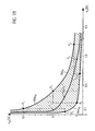
- Fig. 1A is a diagram in which advantageous ranges of the active gas content of a protective gas is shown as a function of the silicon content.
- Fig. 1B is a diagram in which the advantageous areas are made Fig. 1A are approximated and generalized by interpolation lines.
- Fig. 1C is a diagram in which the advantageous areas are made Fig. 1A approximated and generalized by linear interpolation.
- Fig. 2A is a diagram in which advantageous ranges of the helium content of the shielding gas is shown as a function of the silicon content.
- Fig. 2B is a diagram in which the advantageous areas are made Fig. 1A approximated and generalized by linear interpolation.
- FIG. 3 is a diagram in which the advantageous areas of the FIGS. 1A and 2A are shown in a coordinate system, which is formed by the active gas content of a protective gas and its helium content.
- FIG. 4 is a flowchart of a process of determining the shielding gas mixture according to the invention.
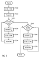
- FIG. 10 is a flowchart of a process of determining the shielding gas mixture including a check routine.
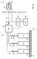
- Fig. 6 is a schematic representation of a welding device with inert gas manufacturing apparatus according to the invention.
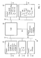
- Fig. 7 Fig. 10 is a block diagram of a control unit of the protective gas manufacturing apparatus according to the invention.
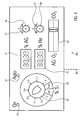
- Fig. 8 Fig. 10 is an illustration of a display and input unit of the protective gas manufacturing apparatus according to the invention.
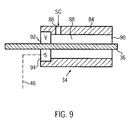
- Fig. 9 is an illustration of a head of a welding machine according to the invention.
- the inventor of the present invention has made experiments with various welding wires with the aim to produce largely slag-free welds in arc welding with abschmelzender electrode. The emphasis was placed on welds on thin sheets up to about 5 mm thickness of unalloyed and weakly alloyed steel.
- protective gas mixtures of argon with an active gas (CO 2 or O 2 or a mixture thereof) and helium were used.
- a standard welding wire which contains between approx. 0.7 - 1.2% Si
- the proportion of the active gas must be chosen very low (-0.5-1.5%) in order to prevent silicate formation. If the arc becomes unstable due to the low proportion of active gas or if the penetration is insufficient, a welding wire with a lower silicon content must be used to enable silicate-free welding with a higher proportion of active gas (as explained above, the silicon almost exclusively enters the weld via the wire) , With a welding wire with lowered Si content ( ⁇ 0.2 - 0.4% Si) then gas mixtures with about 1 - 5% active gas content are used. If a welding filler with a particularly low Si content ( ⁇ 0.05 - 0.1% Si) is used, it is welded under protective gas mixtures with about 3 - 10% active gas content.
- Fig. 1A shown schematically.
- the active gas content v_AG [%] is plotted on the volume of the protective gas over the silicon content w_Si [%] of the wire electrode.
- the areas determined in each case for the different wire types are hatched therein and designated by the respective type identifiers A, B and C.
- the respective optimization points are designated P_A, P_B and P_C and connected to each other by an optimum line Opt_AG.
- Fig. 1B are in a similar representation, the above-mentioned areas A, B and C only hatched with the aim of determining a generalized selection range for the active gas v_AG.
- the respective upper right corner points P1, P2 and P3 of the areas C, B and A are connected to each other and further continued to determine an upper limit Max_AG for the selection area.
- the respective lower left corner points P4, P5 and P6 of the areas C, B and A are connected to each other and further continued to determine a lower limit Min_AG for the selection area.
- the selection area between the two curves Max_AG and Min_AG was hatched in the figure.
- the optimum line Opt_AG is also drawn.
- the lines Max_AG, Min_AG and Opt_AG are in the FIGS. 1A and 1B formed by natural, continuous, monotone and non-negative splines defined by the respective vertices.
- the reference points are shown in detail in the table below: Line base Max_AG Opt_AG Min_AG P1 P2 P3 P_C P_B P_A P4 P5 P6 w_Si [%] 0.1 0.4 1.2 0,075 0.3 0.85 0.05 0.2 0.7 v_AG [%] 10 5 1.5 5 3 1 3 1 0.5
- interpolation instead of a spline interpolation, other types of interpolation can be used, such as a Bézier interpolation, which must of course also be continuous, monotone and non-negative. At three interpolation points a square Bézier curve is possible.
- Fig. 1C a linear interpolation shown.
- the upper limit Max_AG for the Aktivgasanteil v_AG is formed by two outgoing from the base P2, passing through the points P1 and P3 beams, the lower limit Min_AG for Aktivgasanteil v_AG by two from the base P5 outgoing, by the support points P4 or. P6 extending beams formed, and the optimum line Opt_AG for the Aktivgasanteil v_AG by two from the base P_B outgoing, formed by the support points P_C and P_A extending beams.
- the selection area defined thereby is limited in each case by the coordinate axes, since material components can not become negative.
- the selection range can alternatively be limited by the largest and smallest silicon fractions w_Si and active gas fractions v_AG which have occurred in the experiments. This is in the Figure 1C This symbolizes that areas outside the respective extreme points P7 and P8 only dotted hatched. That is, in this case, the active gas portion selection range v_AG is constituted by a closed polygon defined by the points P1, P2, P3, P8, P6, P5, P4, and P7. The coordinates of extreme points P7 and P8 are shown in the following table: Point P7 P8 w_Si [%] 0.05 1.2 v_AG [%] 10 0.5
- the selection range can also be narrowed. This is indicated in the figure by lines Max_AG 'and Min_AG' which run through suitable points offset to the respective optimization point P_C, P_B or P_A. A further narrowed selection area is formed by the lines Max_AG "and Min_AG", in which the interpolation points are at the height of the optimization points.
- the vertices of the lines Max_AG and Min_AG are shown with filled squares, the vertices of the lines Max_AG 'and Min_AG' are represented by empty triangles and the vertices of the lines Max_AG "and Min_AG” are represented by empty circles.
- the interpolation points of the line Opt_AG are shown with filled circles. Suitable interpolation points for the lines Max_AG 'and Min_AG' are given in the following table: Line base Max_AG ' Min_AG ' P1 ' P2 ' P3 ' P4 ' P5 ' P6 ' w_Si [%] 0.1 0.4 1.2 0.05 0.2 0.7 v_AG [%] 7.5 4 1.2 4 2 0.8
- offset vertices may also be used to define spline or other interpolation curves.
- a general teaching is provided for the first time to select the active gas content v_AG in the protective gas as a function of the silicon content in the welding electrode in order to obtain a silicate-free seam surface as possible.
- helium Since the heat conduction, the arc stability and the penetration go down as the proportion of active gas decreases, helium must be added to the protective gas mixture in order to compensate for these effects. Depending on the selected proportion of active gas, the helium content moves between 10 and 70%, with the more helium must be added, the less active gas is present.
- Preferred wire / shielding gas combinations are therefore, for example wire type Si content [%] Active gas content [% Vol] helium content [% Vol] A (standard) 0.7-1.2 1 50 B (middle Si) 0.2-0.4 3 40 C (low-Si) 0.05 -0.1 5 30
- the values given for the helium and the active gas (CO 2 ) are to be understood as approximate average values, which vary depending on the actual Si content and the actual welding result, possibly also on a possible Si content in the material itself are.
- Fig. 2A the relationship described above is shown schematically.
- the helium content v_He [%] is plotted on the volume of the protective gas over the silicon content w_Si [%] of the wire electrode.
- the areas determined in each case for the different wire types are hatched therein and designated by the respective type identifiers A, B and C.
- the respective optimization points are designated Q_A, Q_B and Q_C and are connected to one another by an interpolated optimum line Opt_He.
- Fig. 2B are in a similar representation, the above-mentioned areas A, B and C shown only hatched with the aim of determining a generalized selection range for the helium portion v_He.
- the respective lower right corner points Q4 and Q6 of the regions C and A are linearly connected to each other to determine a lower limit Min_He for the selection region.
- the selection area between the two curves Max_He and Min_He was hatched in the figure.
- a linearized optimum line Opt_He is also drawn in, which likewise takes into account only the optimization points Q1 and Q3 of the regions C and A.
- the respective corner points Q2 and Q4 of the region B are taken into account in the interpolation as well as in the determination of the active gas content. Further improvement in accuracy is achieved by a spline interpolation or Bézier curve or the like.
- the selection area defined in this way is always limited in principle by the coordinate axes, since substance proportions can not become negative.
- the selection range can alternatively be limited by the largest and smallest silicon fractions w_Si and helium fractions v_He that have occurred in the experiments. This is symbolized in the figure by the fact that regions outside the respective extreme points Q7 and Q8 are hatched only by dashed lines. That is, in this case, the selection range for the helium portion v_He is formed by a closed polygon defined by the points Q1, Q2, Q3, Q8, Q6, Q5, Q4 and Q7. The coordinates of extreme points Q7 and Q8 are shown in the following table: Point Q7 Q8 w_Si [%] 0.05 1.2 v_He [%] 50 30
- the selection range for the helium component v_He can also be narrowed. This is in the FIG. 2B indicated by lines Max_He 'and Min_He', which extend through suitable to the respective optimization point P_C, P_B or P_A out offset bases.
- a further narrowed selection range is not useful in the case of linear interpolation with two interpolation points, since otherwise the optimization point Q_B would lie outside the selection range, as can be seen from FIG. 2B is apparent. However, with three interpolation points, further narrowing of the selection range by intersections at the level of the optimumpoints would be considered.
- the vertices of the lines Max_He and Min_He are shown with filled squares, the vertices of the lines Max_He 'and Min_He' are represented by empty triangles and the vertices of the boundary lines of a possible further restricted selection area are represented by empty circles.
- the interpolation points of the line Opt_He are shown with filled circles. Suitable vertices are given for the lines Max_He 'and Min_He' in the following table: Line base Max_He ' Min_He ' Q1 ' Q2 ' Q3 ' Q4 ' Q5 ' Q6 ' w_Si [%] 0.05 0.2 0.7 0.1 0.4 1.2 v_He [%] 40 50 60 20 30 40
- a general teaching is provided to select the helium content v_He in the protective gas as a function of the silicon content in the welding electrode in order to ensure good heat input and transfer within economically acceptable limits with an adjusted active gas content to obtain a silicate-free seam surface.
- Fig. 3 the result of the above discussion is shown in the form of another diagram.
- the helium content v_He is plotted over the active gas content v_AG and the experimentally determined ranges for the three wire types A, B and C are plotted.
- the Optimumpoints These areas are shown as circles and designated as R_A, R_B and RC.
- R_A, R_B and RC By these points Optimum a center line M is defined, which is basically obtained in the manner discussed above by interpolation, but in this case leads in each case to a straight line.
- the respective silicon content w_Si in the wire electrode is known in each case.
- the welding wire In order to avoid problems with faulty welds, it is preferable to choose the welding wire with a high Si content if possible, since silicon ensures good flow and wetting of the molten bath and favors its degassing.
- Fig. 4 shows in the form of a flow chart, the basic procedure when mixing together a suitable inert gas mixture.
- step S100 the silicon content w_Si of the wire electrode is input.
- step S110 the proportion of active gas v_AG is determined as a function of the silicon content w_Si; Then, in step S120, the helium content v_He is determined as a function of the silicon content w_Si.
- step S110 and S120 can be combined in one step.
- step S130 the proportion v_IG of a further inert gas is determined as the remaining proportion.
- step S140 the determined proportions are output in step S140.
- the determined components are then adjusted at a mixing device or by throttling corresponding throttle devices in the supply lines of the individual gases.
- the determination of the active gas content v_AG and of the helium content v_He as a function of the silicon content w_Si can be based on any consideration discussed above for determining the respective selection ranges.
- the determination of shares may be based on tables of values, which are shown in the graphs in the tables FIGS. 1A to 3 have been prepared and present in tabular form in writing or in a memory of a computing unit, or on arithmetic rules that have been defined using the interpolation routines described above and present in diagram form or as hardwired logic or as a program of a logic unit of a computational unit.
- step S200 the above-described steps S100 to S140 are performed. That is, the silicon content w_Si of the wire electrode is inputted, the components v_AG, v_He and v_IG of the active gas, helium and other inert gas are determined as functions of the silicon content w_Si and remaining portions, respectively, and the detected components are outputted to prepare a blanketing gas mixture.
- step S210 a sample weld is made with the selected blanket gas composition and a check is made in step S220 to determine if the slag formation on the seam is acceptable. If this check is positive, the process proceeds to step S250. On the other hand, if the check in step S220 is negative, the flow advances to step S230.
- step S230 the amount of active gas v_AG is varied, and steps S130 and S140 described above are performed in step S235.
- the proportion v_IG of the further inert gas is determined as the remainder of the modified active gas content v_AG and the unchanged helium content v_He, and the new proportions are output to produce a protective gas mixture.
- step S240 a re-sampling is performed in step S240, and the flow returns to the checking step S220.
- step S220 Once the test step S220 has been positive, as mentioned above, the flow proceeds to step S250.
- step S250 it is checked whether the weld meets other quality requirements.
- This quality test may be limited to a mere visual inspection with regard to splashes, for example. It may also include tests of strength, penetration and other parameters. If this test is positive, the process is completed because a suitable inert gas composition has been found. On the other hand, if the check in step S250 is negative, the flow advances to step S260.
- step S260 the helium content v_He is varied, and the above-described steps S130 and S140 are performed in step S265. That is to say, the portion v_IG of the further inert gas is determined as the remainder of the changed helium content v_He and the unchanged proportion of active gas v_AG, and the new proportions are output to produce a blanket gas mixture.
- step S270 a re-sampling is performed in step S270, and the flow returns to the checking step S250.
- test step S250 As soon as the test step S250 has been positive, the process ends, as already mentioned above.
- the helium component v_He can also be adapted to the varied proportion of active gas v_AG in step S230, for example using a diagram as in FIG Fig. 3 or a lookup table or calculation rule created or defined on its basis.
- Fig. 6 schematically shows a welding device 2 according to the invention.
- the welding device 2 basically has a protective gas production device 4 and a welding machine 5.
- components associated with the inert gas producing apparatus 4 are shown to the left of a dash-dotted vertical line, while components which the welding machine 5 are assigned, are shown to the right of the dash-dotted vertical line.
- the connection lines 10, 16, 22 open into a mixing device 26, which serves to mix a protective gas with predetermined proportions of active gas, helium and inert gas.
- inert gas always means the further inert gas, not helium.
- a further inert gas is mainly argon into consideration. Basically, neon, xeon and krypton could be used, but because of their high price will be less used.
- From the mixing device 26 performs a protective gas connection line 28 with a Hauptabsperrventil 30 away.
- the inert gas producing apparatus 4 further includes an electronic control unit (E-CU) 38 serving to control the inert gas producing apparatus 4 and an input / output device (I / O) 40 connected to the ECU 38 via a data line 42 connected is.
- E-CU electronice control unit
- I / O input / output device
- Data input to the I / O 40 is supplied via the data line 42 to the ECU 38, and data to be displayed on or processed by the I / O 40 is supplied to the I / O 40 via the data line 42 from the ECU 38.
- the ECU 38 is further connected to the mixer 26 via a data line 44.
- Via the data line 44 of the mixing device 26 default values for adjusting devices not shown, which serve the mixture of the individual gases in the mixing device 26, supplied from the ECU 38 from. Furthermore, measured values which correspond to actual values of the adjusting devices or the gas components actually achieved are transmitted from the mixing device 26 to the ECU 38 via the data line 44.
- the ECU 46 is further connected to the welding machine 5 via a data line 46.
- the data line 46 serves to exchange signals between the ECU 46 and the welding machine 5.
- the ECU 46 may be connected to the shut-off valves 12, 18, 24 and 30 via further data lines (not shown) to monitor and / or control their condition. These data lines can be combined with the data line 44.
- reservoirs 8, 14, 20 are shown for the purpose of example only in the typical form of gas cylinders. It can be containers of any shape.
- the gases may also be stored in a liquid or solid state and, if necessary, be brought into the gaseous state.
- Corresponding treatment facilities are not shown in detail, but known per se.
- Fig. 7 shows the schematic structure of the ECU 38 by means of a block diagram.
- the input devices 48, 50, 52 are connected to a processing unit (logic) 56.
- a processing unit (logic) 56 is connected via an internal bus 66 to a memory device 58 which holds data required by the logic 56, such as value tables, routines and functions.
- the memory device 58 can also hold an operating system for the operation of the ECU 38, but this can also be kept in a further memory module.
- the processing unit 56 which may be a CPU of a type known per se, the input data and memory data are processed to generate output data, in particular control data for the mixer 26 and display data for the I / O 40.
- the ECU 38 may include other components that serve the function of the same. For example, further input and output devices may be present for exchanging data with the outside world, drives for storage media, a separate display device, etc. Thus, for example, the value tables, routines and functions of the storage device 58 can be updated.
- the logic 56 determines selected values of active gas content, helium content, and inert gas content in the shielding gas as a function of silicon content in the electrode based on value tables, routines, and functions in the storage device 56 based on the selection range and optimum value considerations discussed above Active gas content, the helium content and the inert gas in the inert gas were produced.
- the logic 56 increases or decreases the selected values as a function of the signals "adjustment v_AG” and / or "adaptation v_He".
- the logic 56 disables the mixer 26 or supplies its preselected default values and sets the signal "Power On / Off” to Off when the signal "Manual / Off / Auto” is Off, and sets the signal "Power On / Off”. On if the "Manual / Off / Auto" signal indicates Manual or Auto.
- logic 56 uses the signal “select w_Si" for the calculations when the signal "manual / off / auto” indicates a manual input.
- the logic 56 sets the signal "Auto Select / Pos / Neg” to select if the signal "Manual / Off / Auto” indicates auto-detection.
- the logic 56 uses the signal "w_Si" for the calculations or determines the silicon content from the signal “wire type” if the signal “Manual / Off / Auto” indicates an automatic detection and the signal "w_Si” or the signal “wire type "indicate that automatic detection is possible and in this case set the signal” Auto Select / Pos / Neg "to pos.
- logic 56 sets the signal "Auto Select / Pos / Neg” to Neg when the signal "Manual / Off / Auto” indicates an automatic detection and the signal "w_Si" and the signal “Wire Type” indicate that automatic detection not possible.
- the determined values for the gas components in the protective gas further converts the logic 56 into signals which enable a control of the mixing device.
- the logic 56 may use the feedback signals returned by the mixer 26 to perform a control.
- status signals from the welding machine 5 or monitoring signals can be used to close or open the main shut-off valve 30 and / or the individual shut-off valves 12, 18, 24, thus contributing to plant safety and minimizing gas consumption.
- Fig. 8 shows a control panel of the I / O 40 in plan view with associated controls and indicators.
- the I / O 40 receives input signals from the ECU 38 and sends output signals to the ECU 38 via the data line 42.
- a knob 68 is connected to a switching network and a potentiometer or the like, which has at least two fixed switching positions and a stepless or stepped switching range and generates the signal "Manual / Off / Auto" and the signal "Selection w_Si".
- the signal "Manual / Off / Auto” assumes the value Off.
- the signal “Manual / Off / Auto” assumes the value Auto.
- the signal “Manual / Off / Auto” assumes the value Manual and corresponds to the signal “Selection w_Si" of the position within the shift range.
- Switch positions and the shift range are indicated on a scale 69.
- a light emitting diode 70 indicates the functional status of the device. It preferably glows green when the Power On / Off signal is On, which is output from the ECU 38 when the Manual / Off / Auto signal is not Off.
- a light emitting diode 72 indicates the status of automatic electrode detection and is capable of illuminating in three colors. It is preferably yellow when the signal is Auto Select / Pos / Neg. It preferably glows green when the signal "Auto Select / Pos / Neg” is Pos. It preferably glows red when the signal "Auto Select / Pos / Neg” is Neg.
- the signal "Auto Select / Pos / Neg” can be reduced to a signal "Auto Pos / Neg”.
- the ECU 38 first sets the signal “Auto Pos / Neg” to Neg and sets it to Pos only when the signal "w_Si" or the signal "wire type” indicates that an automatic detection of the silicon content is possible.
- the light emitting diode 72 only needs to have two colors.
- a digital display 74 serves to display the proportion of active gas, while a digital display 76 serves to display the helium content.
- the display of the respective setpoints is provided, but it can alternatively or additionally on separate digital displays (not shown) and the actual value can be specified. It can also be a selector switch (not shown in detail) be provided for selection of actual value or setpoint for display.
- the digital displays 74 and 76 convert the signals "v_AG-Soll” and "v_He-Soll” and / or the signals "v_AG-Ist" and "v_He-Ist". Instead of digital displays and pointer displays can be provided.
- Two knurled knobs 78 and 80 are used to fine tune the active gas and helium portions.
- the associated continuously variable switching networks, potentiometers or the like thus generate the signals "adaptation v_AG” and "adaptation v_He".
- the knobs 78, 80 also have markings that allow accurate positioning by means of scales 79, 81.
- the scales 79, 81 carry no absolute values, but only a zero position and plus and minus areas. If the rotary knobs 78, 80 allow a rotation of more than 180 °, reset devices (not shown in detail) can be provided, which bring the associated instrument back to the zero position.
- a slider 82 makes it possible to specify the proportion of two active gases (here: O 2 and CO 2 ) to one another.
- the slider generates the signal "Selection AG".
- the slider 82 may also be a switch (not shown), which allows a mere switching between two active gases.
- Fig. 9 shows the welding head 34 of the machine 5 in more detail.
- the welding head 34 has a housing 84 with a protective gas connection (SG) 86.
- the protective gas connection 86 opens into a channel 88, which leads to an outlet opening of the housing 84.
- the electrode 36 is guided.
- the electrode 36 is tracked by a feed device 92 which is installed in the housing 84.
- a sensor device 94 is provided which directly determines the type of electrode 36 used or its silicon content w_Si.
- Welding electrodes for welding machines are used today in the form of wires on large rollers.
- a coding can be attached, which enables the sensor device 94 to detect the type or the Si content of the wire.
- Such coding may also be applied periodically or continuously to the wire.
- Possible encodings include diameter, cross-sectional shape, longitudinal grooves, embossing or etching, or simple labels made of paper or plastic, which are removed in the sensor or, in any case, burn when the wire is used.
- the percentages (%) for the protective gas described in the patent application are in percent by volume (% by volume).
Landscapes
- Engineering & Computer Science (AREA)
- Mechanical Engineering (AREA)
- Physics & Mathematics (AREA)
- Plasma & Fusion (AREA)
- Chemical & Material Sciences (AREA)
- Materials Engineering (AREA)
- Arc Welding In General (AREA)
Abstract
Description
- Die vorliegende Erfindung betrifft Verfahren zum Lichtbogenschweißen mit abschmelzender Elektrode von unlegierten und schwach legierten Stählen.
- Es ist bekannt, Schweißdrähte (EN 440) G3Si1 oder G4Si1 zum Schweißen von unlegiertem Stahl bis zu einer Zugfestigkeit von etwa 600 MPa zu verwenden. Diese Drähte enthalten standardmäßig etwa 0,7 - 1,2% Si zur Desoxidation und um das Schmelzbad dünn fließend zu machen.
- Somit enthalten diese Standard-Schweißzusatzwerkstoffe rund das Zehnfache an Silizium verglichen mit den zu schweißenden Grundwerkstoffen. Aufgrund des Mischungsverhältnisses des Schweißnahtmaterials von etwa 30% Grundwerkstoff plus 70% Zusatzwerkstoff beim MAG-Schweißen wird daher über den Schweißdraht das etwa 20 - 25-fache an Silizium in das Schweißnahtmaterial eingebracht, verglichen mit dem Beitrag des Grundwerkstoffes.
- Die Schweißaufgabe wird im Allgemeinen unter einem Schutzgas (EN439) M21 mit 18% CO2 in Argon ausgeführt, was zu starker Silikatbildung auf der Nahtoberfläche führt. Diese Silikate behindern nachfolgende Prozesse wie z.B. KTL-Beschichtung oder Grundierung, da an ihnen die Beschichtungen nicht haften bleiben. Es muss daher ein Arbeitsgang eingeschoben werden, um die Silikate zu entfernen, im Allgemeinen Sandstrahlen oder Schleifen.
- Bekannt sind auch sog. LSi-Drähte mit abgesenktem (- 0,2 - 0,4% Si) oder besonders niedrigem Silizium-Gehalt (0,05 - 0,1 % Si). Diese werden momentan ausschließlich dort eingesetzt, wo nach dem Schweißen noch verzinkt oder emailliert wird, da sich sonst die höher siliziumhaltige Schweißnaht durchzeichnen würde, weil sich mehr Zink oder Emaille an ihr niederschlägt (Sandelin-Kurve). Die Schweißung wird weiterhin unter benanntem Schutzgas ausgeführt, um dem zähen Fließen des Schmelzbades und der hohen Porengefahr entgegen zu wirken, wobei immer noch Silikate an der Nahtoberfläche entstehen.
- Die vorstehend genannte Technologie ist z.B. in: "Pomaska, Schutzgasschweißen, kein Buch mit 7 Siegeln, Infoschriften des Gemeinschaftsausschusses Verzinken e.V." beschrieben.
- Die Entfernung der Silikate erfordert einen aufwendigen und kostenintensiven Zwischenschritt.
- Der vorliegenden Erfindung liegt die Aufgabe zugrunde, die genannten Nachteile im Stand der Technik zu vermeiden. Insbesondere soll der teure Zwischenschritt zur Entfernung der Silikate eingespart werden, um die Wirtschaftlichkeit zu verbessern.
- Um das Anhaften von Schlacken (Silikaten und Oxide anderer Bestandteile des Grundwerkstoffs und von Zusatzstoffen der Schweißelektrode wie Ni, Mo, Cr, Ti, Mn, etc) beim Schweißen von unlegierten und anderen legierten Stählen nach DIN EN 10020 (früher als "niedriglegierte Stähle" bezeichnet) zu verringern, schlägt die
EP 1 714 728 A2 die Verwendung aktiver Schutzgase mit einem Volumenanteil von 0,01 - 0,5 % CO2 oder O2 vor, wobei Werte von 0,01 - 0,4 %, besonders 0,02 - 0,1 %, speziell 0,1 - 0,5 % bevorzugt werden, letzteres in einem Gemisch von Argon mit wenigstens 15 % Helium. - Ohne Bezug zur Schlackenbildung schlägt die
US 4,871,898 allgemein für Stähle Mischungen von 2 - 12 % CO2 und 20 - 45 % Helium vor, wobei die Untergrenze des CO2-Anteils für niedriglegierte Stähle mit 8 % wesentlich höher angegeben wird. - Die
EP 0 494 521 A1 erwähnt im Zusammenhang mit der vorstehenden Druckschrift eine Mischung von 1 % CO2 und 30 % Helium für hochlegierte Stähle (stainless steel) mit dem Handelsnamen HELISTAR SS. - Für hochlegierte Stähle (superalloys) geht die
EP 0 494 521 A1 zunächst von einer vorbekannten Mischung von 2,5 % CO2 und über 85 % Helium aus, was zwar (wohl aufgrund des hohen Helium-Anteils) wenig Spritzer produziere, aber bei Nickelbasierten Legierungen zu starker Oxidation auf der geschweißten Metalloberfläche führe. Ferner diskutiert die Druckschrift eine Mischung von 1 % CO2 und 30 % Helium ebenfalls für hochlegierte Stähle (stainless steel) mit dem Handelsnamen HELISTAR SS. Aus Versuchen mit 1,25 % CO2 + 45 % He (Trial 1), 0,75 % CO2 + 27 % He (Trial 2), 0,5 % CO2 + 18 % He (Trial 3) sowie 0,25 % CO2 + 9 % He (Trial 4) erkennt die Druckschrift das Abnehmen der Oxidation mit sinkendem CO2-Anteil und kommt schließlich zu einer optimalen Mischung von 0,1 - 0,9 % CO2 + 5 - 13 % He für hochlegierte Stähle, insbesondere dünne Bleche hieraus. Der Rest der Schutzgasmischung besteht jeweils aus Argon und Verunreinigungen. - Kurzfassung der Erfindung
- Die Aufgabe der Erfindung besteht darin, für niedriglegierte Stähle ein Schweißverfahren, einen Schweißautomaten, eine Schutzgas-Mischvorrichtung und eine Schweißelektrode anzugeben, die es jeweils ermöglichen, bei gutem Schweißergebnis die Ablagerung von Schlacken, insbesondere Silikaten, auf der Nahtoberfläche zu minimieren.
- Die Aufgabe wird durch die Merkmale der unabhängigen Ansprüche gelöst. Vorteilhafte Weiterbildungen bilden den Gegenstand der Unteransprüche.
- Die Vorliegende Erfindung betrifft das Schweißen von unlegiertem und schwach legiertem Stahl. Als "schwach legierter Stahl" wird ein Stahl bezeichnet, dessen gesamte Legierungskomponenten maximal 6 Gew.% des Stahls und vorzugsweise nicht mehr als 5 Gew.% des Stahls betragen.
- Gemäß einem ersten Gesichtspunkt der Erfindung wird ein Verfahren zum Lichtbogenschweißen von unlegierten oder schwach legierten Stählen mit abschmelzender Elektrode unter Schutzgas bereitgestellt, bei welchem das Schutzgas ein Gemisch ist, das wenigstens Helium und ein Aktivgas sowie ein weiteres Inertgas aufweist. Bei diesem Verfahren wird in Abhängigkeit des Si-Gehaltes eines als Elektrode verwendeten Schweißdrahtes die Zusammensetzung des Schutzgases bestimmt.
Wenn der Schweißdraht eine Normalelektrode ist, beträgt der Anteil des Aktivgases am Gesamtvolumen des Schutzgases mehr als 0,5 % bis etwa 1,5 % beträgt und der Anteil des Heliums am Gesamtvolumen des Schutzgases beträgt mehr als 30 %.
Wenn der Schweißdraht einen verringertem bzw. mittlerem Si-Gehalt von insbesondere etwa 0,2 % bis etwa 0,4 % aufweist, beträgt der Anteil des Aktivgases am Gesamtvolumen des Schutzgases etwa 1 % bis etwa 5 %.
Wenn der Schweißdraht einen niedrigen Si-Gehalt von insbesondere etwa 0,05 % bis etwa 0,1 % aufweist, beträgt der Anteil des Aktivgases am Gesamtvolumen des Schutzgases etwa 3 % bis etwa 10 %. - Mit dem erfindungsgemäßen Verfahren werden geeignete Schutzgasmischungen für bestimmte Elektrodentypen zur Verfügung gestellt. Damit wird gelehrt, den Aktivgasanteil im Schutzgas in Abhängigkeit von dem Siliziumgehalt in der Schweißelektrode auszuwählen, um eine möglichst silikatfreie Nahtoberfläche zu erhalten.
- Zudem ist es möglich den Helium-Anteil im Schutzgas in Abhängigkeit von dem Siliziumgehalt in der Schweißelektrode auszuwählen, um bei angepasstem Aktivgasgehalt zur Gewinnung einer möglichst silikatfreien Nahtoberfläche einen guten Wärmeeintrag und -übergang in wirtschaftlich vertretbaren Grenzen sicherzustellen.
- Gemäß einem zweiten Gesichtspunkt der Erfindung wird ein Verfahren zum Lichtbogenschweißen von unlegierten oder schwach legierten Stählen mit abschmelzender Elektrode unter Schutzgas vorgeschlagen, bei welchem das Schutzgas ein Gemisch ist, das wenigstens Helium und ein Aktivgas sowie ein weiteres Inertgas aufweist, wobei der Anteil des Aktivgases am Gesamtvolumen des Schutzgases mehr als 0,5 % bis etwa 1,5 % beträgt und der Anteil des Heliums am Gesamtvolumen des Schutzgases mehr als 30 % beträgt.
- Mit einem solchen Verfahren wird die Zusammensetzung des Schutzgases so gewählt, dass bei Verwendung einer Normalelektrode mit einem Siliziumgehalt von 0,7 bis 1,2 % die Silikatbildung auf der Naht minimiert und trotzdem ein für eine sichere Schweißung ausreichender Wärmeübergang und -eintrag erzielt und die Spritzerneigung verringert werden kann.
- Bei dem Ausführungsbeispiel gemäß dem zweiten Gesichtspunkt kann der Anteil des Aktivgases am Gesamtvolumen des Schutzgases wenigstens 0,8 % und/oder höchstens 1,2 %, vorzugsweise etwa 1 % betragen.
- Der Anteil des Heliums am Gesamtvolumen des Schutzgases beträgt dann höchstens 70 %. Der Anteil des Heliums am Gesamtvolumen des Schutzgases beträgt wenigstens 40 %, insbesondere mehr als 45 %, und höchstens 60%, vorzugsweise etwa 50 %.
- Gemäß einem dritten Gesichtspunkt der Erfindung wird ein Verfahren zum Lichtbogenschweißen mit abschmelzender Elektrode unter Schutzgas vorgeschlagen, bei welchem ein Schweißdraht mit verringertem bzw. mittlerem Si-Gehalt von insbesondere etwa 0,2 % bis etwa 0,4 % verwendet wird und das Schutzgas ein Gemisch ist, das wenigstens Helium und ein Aktivgas sowie ein weiteres Inertgas aufweist, wobei der Anteil des Aktivgases am Gesamtvolumen des Schutzgases etwa 1 % bis etwa 5 % beträgt.
- Mit einem solchen Verfahren wird dem Siliziumgehalt des Schweißdrahtes in der Weise Rechnung getragen, dass bei geringerem Siliziumeintrag in die Schweißnaht als bei Verwendung einer Normalelektrode (mit höherem Siliziumgehalt) aufgrund eines höher gewählten Anteils an Aktivgas im Schutzgas ein besserer Wärmeübergang und -eintrag erzielt und die Spritzerneigung verringert werden kann bei weiterhin geringer Silikatbildung.
- Bei dem Ausführungsbeispiel gemäß dem dritten Gesichtspunkt kann der Anteil des Aktivgases am Gesamtvolumen des Schutzgases etwa 2 % bis etwa 4 %, vorzugsweise etwa 3 % betragen.
- Der Anteil des Heliums am Gesamtvolumen des Schutzgases beträgt dann etwa 10 % bis etwa 70 %, insbesondere etwa 20 % bis etwa 60 %, vorzugsweise etwa 30 % bis etwa 50 %, besonders bevorzugt etwa 40 %.
- Gemäß einem vierten Gesichtspunkt der Erfindung wird ein Verfahren zum Lichtbogenschweißen mit abschmelzender Elektrode unter Schutzgas vorgeschlagen, bei welchem ein Schweißdraht mit niedrigem Si-Gehalt von insbesondere etwa 0,05 % bis etwa 0,1 % verwendet wird und das Schutzgas ein Gemisch ist, das wenigstens Helium und ein Aktivgas sowie ein weiteres Inertgas aufweist, wobei der Anteil des Aktivgases am Gesamtvolumen des Schutzgases etwa 3 % bis etwa 10 % beträgt.
- Mit einem solchen Verfahren wird dem Siliziumgehalt des Schweißdrahtes in der Weise Rechnung getragen, dass bei geringeren Siliziumeintrag in die Schweißnaht als bei Verwendung einer Normalelektrode oder einer Mittel-Si-Elektrode aufgrund eines höher gewählten Anteils an Aktivgas im Schutzgas ein noch besserer Wärmeübergang und -eintrag erzielt und die Spritzerneigung verringert werden kann bei weiterhin geringer Silikatbildung.
- Bei dem Ausführungsbeispiel gemäß dem vierten Gesichtspunkt kann der Anteil des Aktivgases am Gesamtvolumen des Schutzgases etwa 4 % bis etwa 7,5 %, vorzugsweise etwa 5 % betragen.
- Der Anteil des Heliums am Gesamtvolumen des Schutzgases beträgt dann etwa 10 % bis etwa 70 %, insbesondere etwa 20 % bis etwa 50 %, vorzugsweise etwa 30 %.
- Gemäß dem erfindungsgemäßen Verfahren werden ausschließlich Schweißdrähte mit einem Siliziumgehalt von etwa 0,7 bis 1,2 %, mit einem Si-Gehalt von etwa 0,2 % bis etwa 0,4 % und mit einem Si-Gehalt von etwa 0,05 % bis 0,1 % verwendet.
- Gemäß einem fünften Gesichtspunkt der Erfindung wird ein Verfahren zum Lichtbogenschweißen mit abschmelzender Elektrode unter Schutzgas vorgeschlagen, bei welchem das Schutzgas ein Gemisch ist, das wenigstens Helium und ein Aktivgas sowie ein weiteres Inertgas aufweist, wobei der Anteil des Aktivgases (und des Heliums) in dem Schutzgas in Abhängigkeit von dem Silizium-gehalt des Schweißdrahts bestimmt wird.
- Mit einem solchen Verfahren wird der Siliziumgehalt des Schweißdrahtes derart berücksichtigt, dass der Aktivgasanteil an das Ausmaß des Siliziumeintrags in die Schweißnaht angepasst werden kann und daher sowohl die Silikatbildung auf der Schweißnaht minimiert bzw. beseitigt werden kann und dennoch ein optimaler, d.h., größtmöglicher Wärmeübergang und -eintrag erzielt werden kann bei verringerter Spritzerneigung.
- Vorzugsweise werden die Obergrenze und die Untergrenze des Aktivgasanteils und/oder des Helium-Anteils durch Interpolation von Randpunkten experimentell ermittelter Bereiche bestimmt oder werden Aktivgasanteil und/oder Helium-Anteil durch Interpolation oder von experimentell ermittelten Optimumpunkten ausgewählt.
- Auswahlbereiche können durch den jeweils größten Stützwert der oberen Interpolationslinie nach oben und durch den jeweils kleinsten Stützwert der unteren Interpolationslinie nach unten begrenzt sein. Zum Zwecke einer schnelleren Konvergenz kann es sinnvoll sein, die Stützpunkte der Interpolationslinien zu den Optimumpunkten hin zu verschieben, um so die Auswahlbereiche zu verengen.
- Die in diesem Gesichtspunkt erwähnten Interpolationslinien können beispielsweise als Streckenzug, als natürlicher, stetiger, monotoner und nichtnegativer Spline, als stetige, monotone und nichtnegative, insbesondere quadratische Bézierkurve oder dergleichen bestimmt sein.
- Bei den vorgenannten Verfahren können Prüfschritte vorgesehen sein, bei denen der Aktivgasanteil und/oder der Heliumanteil auf einen gemäß der jeweils angegebenen Vorschrift ausgewählten Wert eingestellt und dann nach Testschweißung und Prüfung der Schweißnaht auf Silikatablagerung und/oder sonstiger Qualitätsmerkmale innerhalb der jeweils angegebenen Grenzen iterativ variiert werden, bis annehmbare Ergebnisse erreicht sind.
- Die Obergrenze des Aktivgasanteils kann durch eine obere Interpolationslinie (Max_AG) gebildet werden und die Untergrenze des Aktivgasanteils kann durch eine untere Interpolationslinie (Min_AG) gebildet werden, die jeweils wenigstens die in nachstehender Tabelle angegebenen Stützpunkte (P1-P3, P4-P6) aufweisen:
Max_AG Min_AG P1 P2 P3 P4 P5 P6 w_Si [%] 0,1 0,4 1,2 0,05 0,2 0,7 v_AG [%] 10 5 1,5 3 1 0,5 - Die Obergrenze des Aktivgasanteils kann durch eine obere Interpolationslinie (Max_AG') gebildet werden und die Untergrenze des Aktivgasanteils kann durch eine untere Interpolationslinie (Min_AG') gebildet werden, die jeweils wenigstens die in nachstehender Tabelle angegebenen Stützpunkte (P1'-P3', P4'-P6') aufweisen:
Max_AG' Min_AG' P1' P2' P3' P4' P5' P6' w_Si [%] 0,1 0,4 1,2 0,05 0,2 0,7 v_AG [%] 7,5 4 1,2 4 2 0,8 - Die Obergrenze des Aktivgasanteils kann durch eine obere Interpolationslinie (Max_AG") gebildet werden und die Untergrenze des Aktivgasanteils kann durch eine untere Interpolationslinie (Min_AG") gebildet werden, die jeweils wenigstens die in nachstehender Tabelle angegebenen Stützpunkte (P1"-P3", P4"-P6") aufweisen:
Max_AG" Min_AG" P1" P2" P3" P4" P5" P6" w_Si [%] 0,1 0,4 1,2 0,05 0,2 0,7 v_AG [%] 5 3 1 5 3 1 - Der Aktivgasanteil kann durch den jeweils größten Stützwert der oberen Interpolationslinie (Max_AG, Max_AG', Max_AG") nach oben und durch den jeweils kleinsten Stützwert der unteren Interpolationslinie (Min_AG", Min_AG", Min_AG") nach unten begrenzt sein.
- Der Aktivgasanteil kann durch eine Interpolationslinie (Opt_AG) bestimmt werden, die wenigstens die in nachstehender Tabelle angegebenen Stützpunkte (P_C, P_B, P_A) aufweist:
OPT_AG P_C P_B P_A w_Si [%] 0,075 0,3 0,95 v_AG [%] 5 3 1 - Der Anteil des Heliums am Gesamtvolumen des Schutzgases kann etwa 10 % bis etwa 70 % betragen.
- Der Anteil des Heliums in dem Schutzgas wird in Abhängigkeit von dem Siliziumgehalt des Schweißdrahts bestimmt.
- Die Obergrenze des Heliumanteils kann durch eine Gerade (Max_He) begrenzt werdem, die der Gleichung


- Der Heliumanteil kann durch eine Interpolationslinie (Opt_He) bestimmt werden, die wenigstens die in nachstehender Tabelle angegebenen Stützpunkte aufweist:
OPT_He Q_C Q_B P_A w_Si [%] 0,075 0,3 0,95 v_He [%] 30 40 50 - Der Heliumanteil kann durch eine Gerade (Opt_He') bestimmt werden, die der Gleichung

- Die Interpolationslinien der unterschiedlichen Gesichtspunkte der vorliegenden Erfindung können auch als Streckenzug, als natürlicher, stetiger, monotoner und nichtnegativer Spline, oder als stetige, monotone und nichtnegative, insbesondere quadratische Bézierkurve bestimmt sein.
- Das erfindungsgemäße Verfahren nach einem der obigen Gesichtspunkte kann einen Schlackenprüfschritt umfassen, bestehend aus:
- Einstellen des Aktivgasanteils auf einen gemäß der jeweils angegebenen Vorschrift ausgewählten Wert; und
- iteratives Durchführen einer Testschweißung mit dem zu schweißenden Werkstoff, Prüfen der Schweißnaht auf Schlackeablagerungen sowie gegebenenfalls Variieren des Aktivgasanteils innerhalb der jeweils angegebenen Grenzen, bis die Schlackeablagerung annehmbar ist.
- Das erfindungsgemäße Verfahren nach einem der obigen Gesichtspunkte kann einen Qualitätsprüfschritt umfassen, bestehend aus:
- Einstellen des Heliumanteils auf einen gemäß der jeweils angegebenen Vorschrift ausgewählten Wert; und
- iteratives Prüfen sonstiger Qualitätsmerkmale der Schweißnaht und gegebenenfalls Variieren des Heliumanteils innerhalb der angegebenen Grenzen, bis die gewünschte oder maximal erzielbare Qualität erreicht ist.
- Das erfindungsgemäße Verfahren nach dem fünften Gesichtspunkte kann zusätzlich folgende Schritte umfassen:
- manuelles Eingeben des Siliziumgehalts des verwendeten Schweißdrahts; und
- automatisches Einstellen des Aktivgasgehalts und/oder des Heliumanteils des Aktivgases in Abhängigkeit von dem Siliziumgehalt des Schweißdrahts.
- Das erfindungsgemäße Verfahren nach dem fünften Gesichtspunkte kann alternativ folgende Schritte umfassen:
- automatisches Erkennen des Siliziumgehalts des verwendeten Schweißdrahts; und
- automatisches Einstellen des Aktivgasgehalts und/oder des Heliumanteils des Aktivgases in Abhängigkeit von dem Siliziumgehalt des Schweißdrahts.
- Die eben beschriebenen Verfahren nach dem ersten bis zum fünften Gesichtspunkt der vorliegenden Erfindung stellen jeweils einen eigenständigen Erfindungsgedanken dar, die einzeln oder auch in beliebiger Kombination angewendet werden können.
- Mit den Verfahren gemäß dem dritten bis fünften Gesichtspunkt der vorliegenden Erfindung werden vorzugsweise unlegierte Stähle oder schwach legierte Stähle geschweißt.
- Das Schutzgas, nach einem der oben genannten Gesichtspunkte, kann zusätzlich stickstoffhaltige Verbindungen, wie z.B. N2, NO, N2O, NO2, im Bereich von bis zu 5000 ppm aufweisen. Zur zusätzlichen Verbesserung des Wärmeübergangs und zur Reduktion der Silikate kann noch gasförmiger Wasserstoff (H2) im Bereich von 1 bis 5 Vol.-% vorgesehen sein.
- Gemäß einem weiteren Gesichtspunkt der vorliegenden Erfindung wird eine Schutzgas-Herstellungsvorrichtung vorgeschlagen, aufweisend: jeweilige Vorratsbehälter wenigstens für ein Aktivgas, Helium und ein weiteres Inertgas in gasförmigem, flüssigem oder festem Aggregatzustand; eine Dosiereinrichtung zum Dosieren der aus den Vorratsbehältern zugeführten Gase; und eine Steuereinrichtung zum Ansteuern der Dosiereinrichtung, um die Volumenanteile der jeweiligen Gase entsprechend vorgegebenen Werten selbsttätig zu regulieren, wobei die Steuereinrichtung eine Empfangseinrichtung, die angepasst ist, ein einem Siliziumanteil eines Schweißdrahts entsprechendes Signal zu empfangen, und eine Verarbeitungseinrichtung, die angepasst ist, in Abhängigkeit von dem empfangenen Signal Vorgabewerte für die Volumenanteile der jeweiligen Gase zu ermitteln, wobei die Verarbeitungseinrichtung vorzugsweise angepasst ist, den Vorgabewert für den Aktivgasanteil und/oder den Heliumanteil gemäß einem Verfahren des vorstehend beschriebenen Gesichtspunkts zu ermitteln.
- Die Steuereinrichtung kann eine Anzeigeeinrichtung zum Anzeigen von Soll- und/oder Istwerten des Aktivgasanteils und/oder des Heliumanteils aufweisen.
- Die Steuereinrichtung kann eine Silizium-Eingabeeinrichtung zum Eingeben des Siliziumanteils des Schweißdrahts aufweisen.
- Die Steuereinrichtung kann eine Speichereinrichtung zum Speichern von Siliziumanteilen verschiedener Schweißdrahttypen und eine Auswahleinrichtung zum Auswählen eines aus mehreren Schweißdrahttypen aufweisen.
- Die Steuereinrichtung kann eine Aktivgas-Justiereinrichtung zum manuellen Nachjustieren des Vorgabewerts für den Aktivgasanteil und/oder eine Helium-Justiereinrichtung zum manuellen Nachjustieren des Vorgabewerts für den Heliumanteil aufweisen.
- Die Steuereinrichtung kann ferner eine Aktivgas-Auswahleinrichtung zum manuellen Auswählen eines oder mehrerer aus einer Mehrzahl von bevorrateten Aktivgasen oder eines Mischungsverhältnisses aus diesen aufweisen.
- Die Schutzgas-Herstellungsvorrichtung kann eine Überrangeinrichtung zum Deaktivieren der Steuereinrichtung oder der Verarbeitungseinrichtung zum Berechnen der Vorgabewerte in Abhängigkeit von dem Siliziumanteil aufweisen.
- Mit einer solchen Schutzgas-Herstellungsvorrichtung ist es möglich, in Abhängigkeit von dem Siliziumanteil eines Schweißdrahts ein Schutzgas selbsttätig zu erzeugen, das hinsichtlich der Silikatbildung auf der Naht optimiert ist bzw. silikatfreies Schweißen ermöglicht und hinsichtlich Wärmeeintrag und -übertragung bestmöglich ausgelegt ist.
- Wenn die Steuereinrichtung eine Silizium-Eingabeeinrichtung zum Eingeben des Siliziumanteils des Schweißdrahts aufweist, kann der Bediener durch einfaches Eingeben des Siliziumanteils für ein optimal eingestelltes Schutzgas sorgen.
- Wenn die Steuereinrichtung eine Speichereinrichtung zum Speichern von Siliziumanteilen verschiedener Schweißdrahttypen und eine Auswahleinrichtung zum Auswählen eines aus mehreren Schweißdrahttypen aufweist, kann der Bediener ferner durch einfaches Auswählen des Schweißdrahttyps für ein optimal eingestelltes Schutzgas sorgen.
- Durch Justiereinrichtungen zum manuellen Nachjustieren der Vorgabewerte für den Aktivgasanteil und/oder den Helium-Anteil kann das Ergebnis der Schweißung optimiert werden.
- Bevorzugt ist vorgesehen, dass die Schutzgas-Herstellungsvorrichtung eine Überrangeinrichtung zum Deaktivieren der Steuereinrichtung oder der Berechnungslogik zum Berechnen der Vorgabewerte in Abhängigkeit von dem Siliziumanteil aufweist. Damit wird ermöglicht, eine Schutzgasmischung durch manuelle Vorgabe der Sollwerte oder durch manuelle Betätigung der Dosiereinrichtung auch dann einzustellen, wenn ein unbekannter Schweißdrahttyp oder ein Schweißdraht mit unbekanntem Siliziumanteil verwendet wird oder wenn Materialien verschweißt werden sollen, für welche die Vorgabe anhand des Siliziumanteils keine Vorteile bringt.
- Gemäß einem weiteren Gesichtspunkt wird eine Schweißvorrichtung vorgeschlagen, die eine Schutzgas-Herstellungseinrichtung gemäß dem vorstehend erwähnten Gesichtspunkt aufweist. Die Schweißvorrichtung kann ein Schweißautomat sein.
- Die Schweißvorrichtung kann eine Erkennungseinrichtung zum Erkennen des Typs oder des Siliziumgehalts des Schweißdrahts und eine Ausgabeeinrichtung zum Ausgeben eines das Erkennungsmerkmal wiedergebenden Signals aufweisen. Damit ist eine automatische Einstellung der Schutzgasmischung in Abhängigkeit von dem Siliziumgehalt der Schweißelektrode im Hinblick auf eine silikatfreie Schweißnaht möglich.
- Gemäß einem weiteren Gesichtspunkt wird ein Schweißdraht vorgeschlagen, der eine Kodierung für seinen Siliziumgehalt oder seinen Typ aufweist.
- In allen Gesichtspunkten der Erfindung wird durch geschickte Kombination des Standard- oder eines LSi-Drahtes mit einem Schutzgas, dessen aktiver Bestandteil soweit abgesenkt wird, bis keine Silikate mehr an der Nahtoberfläche entstehen, und in das gleichzeitig Helium eingemischt wird, um den Wärmeübergang zu verbessern und somit der Porengefahr und einem zähen Fließen des Schmelzbades entgegen zu wirken, eine problemlose Verschweißung dieser Drahttypen ermöglicht und gleichzeitig das Problem mit den Oberflächensilikaten gelöst.
- Dadurch werden diese Draht/Gas-Kombinationen für alle Industrien interessant, die sich das lästige Entfernen der Silikate einsparen wollen, insbesondere Massenproduzenten wie z.B. die Automobil- und deren Zulieferindustrie.
- Weitere Gesichtspunkte, Vorteile und Merkmale der vorliegenden Erfindung werden aus der nachstehenden genauen Beschreibung und zeichnerischen Darstellung bevorzugter Ausführungsbeispiele ersichtlich werden.
-
Fig. 1A ist ein Diagramm, in welchem vorteilhafte Bereiche des Aktivgasanteils eines Schutzgases in Abhängigkeit von dem Siliziumgehalt dargestellt ist. -
Fig. 1B ist ein Diagramm, in welchem die vorteilhaften Bereiche ausFig. 1A durch Interpolationslinien angenähert und verallgemeinert sind. -
Fig. 1C ist ein Diagramm, in welchem die vorteilhaften Bereiche ausFig. 1A durch lineare Interpolation angenähert und verallgemeinert sind. -
Fig. 2A ist ein Diagramm, in welchem vorteilhafte Bereiche des Heliumanteils des Schutzgases in Abhängigkeit von dem Siliziumgehalt dargestellt ist. -
Fig. 2B ist ein Diagramm, in welchem die vorteilhaften Bereiche ausFig. 1A durch lineare Interpolation angenähert und verallgemeinert sind. -
Fig. 3 ist ein Diagramm, in welchem die vorteilhaften Bereiche aus denFign. 1A und2A in einem Koordinatensystem dargestellt sind, das von dem Aktivgasanteil eines Schutzgases und seinen Heliumanteil gebildet ist. -
Fig. 4 ist ein Ablaufdiagramm eines Prozesses einer Bestimmung des Schutzgasgemischs gemäß der Erfindung. -
Fig. 5 ist ein Ablaufdiagramm eines Prozesses einer Bestimmung des Schutzgasgemischs einschließlich einer Prüfroutine. -
Fig. 6 ist eine schematische Darstellung einer Schweißeinrichtung mit Schutzgas-Herstellungsvorrichtung gemäß der Erfindung. -
Fig. 7 ist ein Blockschaubild einer Steuereinheit der Schutzgas-Herstellungsvorrichtung gemäß der Erfindung. -
Fig. 8 ist eine Darstellung einer Anzeige- und Eingabeeinheit der Schutzgas-Herstellungsvorrichtung gemäß der Erfindung. -
Fig. 9 ist eine Darstellung eines Kopfes eines Schweißautomaten gemäß der Erfindung. - Der Erfinder der vorliegenden Erfinderung hat Versuche mit verschiedenen Schweißdrähten angestellt mit dem Ziel, beim Lichtbogenschweißen mit abschmelzender Elektrode weitgehend schlackefreie Schweißnähte zu erzeugen. Der Schwerpunkt wurde dabei auf Schweißungen an dünnen Blechen bis etwa 5 mm Stärke aus unlegiertem und schwach legiertem Stahl gelegt. Als Schutzgas wurden Mischungen von Argon mit einem Aktivgas (CO2 oder O2 oder ein Gemisch hieraus) und Helium verwendet.
- Bei vergleichsweise niedrigen Anteilen von Aktivgas im Schutzgas bildeten sich besonders schlackearme Schweißnähte. Bei stark abgesenktem Aktivgasanteil war es jedoch erforderlich, den Heliumanteil im Schutzgas zu erhöhen, um den Wärmeeintrag in die Schweißnaht und die Wärmeübertragung zu verbessern. Aus Kostengründen strebt man aber tendenziell an, den Heliumverbrauch gering zu halten. Für das Schweißschutzgas haben sich grundsätzlich folgende Zusammensetzungen als vorteilhaft erwiesen:
- Heliumanteil: 10 - 70%, bevorzugt 20 - 60%, bes. insbesondere 30 - 50%
- Aktivgasanteil (O2/ CO2): 0 - 10%, bevorzugt 0,5 - 8%, insbesondere 1 - 5%
- Es wurden grundsätzlich drei Drahttypen mit unterschiedlichem Gehalt an Silizium (Si) verwendet. Überraschenderweise stellte sich heraus, dass der optimale Bereich für den Aktivgasanteil stark von dem verwendeten Drahttyp abhängt. Abhängig vom verwendeten Drahttyp wird nämlich das Ziel, silikatfrei zu schweißen, mit unterschiedlichen Gasgemischen erreicht, wobei tendenziell umso mehr Aktivgas (CO2 oder O2) im Schutzgasgemisch vorhanden sein darf, je weniger Silizium im Draht vorhanden ist. Die Ergebnisse lassen sich tabellarisch darstellen wie folgt:
Drahttyp Si-Gehalt
[%]Aktivgasanteil
[% Vol]Optimum
[% Vol]A 0,7 - 1,2 0,5 - 1,5 1,0 B 0,2 - 0,4 1,0 - 5,0 3,0 C 0,05 -0,1 3,0 - 10,0 5,0 - Wird ein Standard-Schweißdraht verwendet, der zwischen ca. 0,7 - 1,2% Si enthält, muss der Anteil des Aktivgases sehr niedrig gewählt werden (- 0,5 - 1,5%), um die Silikatbildung verhindern zu können. Wird aufgrund des niedrigen Aktivgasanteils der Lichtbogen instabil oder ist der Einbrand nicht ausreichend, muss ein Schweißdraht mit geringerem Siliziumgehalt verwendet werden, um ein silikatfreies Schweißen bei höherem Aktivgasanteil zu ermöglichen (wie oben erläutert, kommt das Silizium fast ausschließlich über den Draht in die Schweißnaht). Mit einem Schweißdraht mit abgesenktem Si-Gehalt (∼ 0,2 - 0,4% Si) kommen dann Gasgemische mit ca. 1 - 5% Aktivgasanteil zum Einsatz. Wird ein Schweißzusatz mit besonders niedrigem Si-Gehalt (∼ 0,05 - 0,1 % Si) verwendet, verschweißt man ihn unter Schutzgasgemischen mit ca. 3 - 10% Aktivgasanteil.
- Dieser Zusammenhang ist in
Fig. 1A schematisch dargestellt. Dort ist der Aktivgasanteil v_AG [%] am Volumen des Schutzgases über den Siliziumgehalt w_Si [%] der Drahtelektrode aufgetragen. Die jeweils ermittelten Bereiche für die verschiedenen Drahttypen sind darin schraffiert und mit den jeweiligen Typkennzeichen A, B und C bezeichnet. Die jeweiligen Optimumpunkte sind mit P_A, P_B und P_C bezeichnet und durch eine Optimumlinie Opt_AG miteinander verbunden. - In
Fig. 1B sind in einer ähnlichen Darstellung die vorstehend genannten Bereiche A, B und C nur schraffiert dargestellt mit dem Ziel, einen verallgemeinerten Auswahlbereich für den Aktivgasanteil v_AG zu bestimmen. Zu diesem Zweck werden die jeweiligen oberen rechten Eckpunkte P1, P2 und P3 der Bereiche C, B und A miteinander verbunden und darüber hinaus fortgesetzt, um eine Obergrenze Max_AG für den Auswahlbereich zu ermitteln. Gleichermaßen werden die jeweiligen unteren linken Eckpunkte P4, P5 und P6 der Bereiche C, B und A miteinander verbunden und darüber hinaus fortgesetzt, um eine Untergrenze Min_AG für den Auswahlbereich zu ermitteln. Der Auswahlbereich zwischen den beiden Kurven Max_AG und Min_AG wurde in der Figur schraffiert. Zur Orientierung ist auch die Optimumlinie Opt_AG eingezeichnet. - Die Linien Max_AG, Min_AG und Opt_AG sind in den
Fign. 1A und1B durch natürliche, stetige, monotone und nichtnegative Splines gebildet, die durch die jeweiligen Stützpunkte definiert sind. Die Stützstellen sind im Einzelnen in der nachstehenden Tabelle wiedergegeben:Linie Stützpunkt Max_AG Opt_AG Min_AG P1 P2 P3 P_C P_B P_A P4 P5 P6 w_Si [%] 0,1 0,4 1,2 0,075 0,3 0,85 0,05 0,2 0,7 v_AG [%] 10 5 1,5 5 3 1 3 1 0,5 - Weitere Stützpunkte, etwa geeignete Achsenabschnitte, können bei Bedarf hinzugezogen werden.
- Statt einer Spline-Interpolation können auch andere Interpolationsarten Anwendung finden, wie etwa eine Bézier-Interpolation, die natürlich ebenfalls stetig, monoton und nichtnegativ sein muss. Bei drei Stützpunkten kommt eine quadratische Bézierkurve in Betracht.
- Als besonders einfache Interpolation ist in
Fig. 1C eine lineare Interpolation dargestellt. Dabei wird die Obergrenze Max_AG für den Aktivgasanteil v_AG durch zwei von dem Stützpunkt P2 ausgehende, durch die Sützpunkte P1 bzw. P3 verlaufende Strahlen gebildet, wird die Untergrenze Min_AG für den Aktivgasanteil v_AG durch zwei von dem Stützpunkt P5 ausgehende, durch die Sützpunkte P4 bzw. P6 verlaufende Strahlen gebildet, und wird die Optimumlinie Opt_AG für den Aktivgasanteil v_AG durch zwei von dem Stützpunkt P_B ausgehende, durch die Sützpunkte P_C bzw. P_A verlaufende Strahlen gebildet. Der hierdurch definierte Auswahlbereich ist jeweils durch die Koordinatenachsen begrenzt, da Stoffanteile nicht negativ werden können. - Der Auswahlbereich kann alternativ durch die in den Experimenten aufgetretenen größten und kleinsten Siliziumanteile w_Si und Aktivgasanteile v_AG begrenzt werden. Dies wird in der
Figur 1C dadurch symbolisiert, dass Bereiche außerhalb der jeweiligen Extrempunkte P7 und P8 nur gepunktet schraffiert sind. Das heißt, in diesem Fall wird der Auswahlbereich für den Aktivgasanteil v_AG durch ein geschlossenes Vieleck gebildet, das durch die Punkte P1, P2, P3, P8, P6, P5, P4 und P7 definiert ist. Die Koordinaten der Extrempunkte P7 und P8 sind in nachstehender Tabelle wiedergegeben:Punkt P7 P8 w_Si [%] 0,05 1,2 v_AG [%] 10 0,5 - Um ferner im Prozessablauf eine größere Treffsicherheit und schnellere Konvergenz bei der Auswahl des Aktivgasanteils v_AG zu erzielen, kann der Auswahlbereich auch verengt werden. Dies ist in der Figur durch Linien Max_AG' und Min_AG' angedeutet, die durch geeignet zum jeweiligen Optimumpunkt P_C, P_B bzw. P_A hin versetzte Stützpunkte verlaufen. Ein weiter verengter Auswahlbereich wird durch die Linien Max_AG" und Min_AG" gebildet, bei denen die Stützpunkte auf der Höhe der Optimumpunkte liegen. In der
Figur 1C sind die Stützpunkte der Linien Max_AG und Min_AG mit gefüllten Quadraten dargestellt, sind die Stützpunkte der Linien Max_AG' und Min_AG' durch leere Dreiecke dargestellt und sind die Stützpunkte der Linien Max_AG" und Min_AG" durch leere Kreise dargestellt. Die Stützpunkte der Linie Opt_AG sind mit gefüllten Kreisen dargestellt. Geeignete Stützpunkte sind für die Linien Max_AG' und Min_AG' sind in nachstehender Tabelle wiedergegeben:Linie Stützpunkt Max_AG' Min_AG' P1' P2' P3' P4' P5' P6' w_Si [%] 0,1 0,4 1,2 0,05 0,2 0,7 v_AG [%] 7,5 4 1,2 4 2 0,8 - Geeignete Stützpunkte für die Linien Max_AG" und Min_AG" sind in nachstehender Tabelle wiedergegeben:
Linie Stützpunkt Max_AG" Min_AG" P1" P2" P3" P4" P5" P6" w_Si [%] 0,1 0,4 1,2 0,05 0,2 0,7 v_AG [%] 5 3 1 5 3 1 - Es versteht sich, dass die vorstehenden versetzten Stützpunkte auch zur Definition von Spline- oder anderen Interpolationskurven verwendet werden können.
- Damit wird erstmals eine allgemeine Lehre bereitgestellt, den Aktivgasanteil v_AG im Schutzgas in Abhängigkeit von dem Siliziumgehalt in der Schweißelektrode auszuwählen, um eine möglichst silikatfreie Nahtoberfläche zu erhalten.
- Da mit sinkendem Aktivgasanteil auch die Wärmeleitung, die Lichtbogenstabilität und der Einbrand zurückgehen, muss dem Schutzgasgemisch Helium zugegeben werden, um diese Effekte zu kompensieren. Abhängig von dem gewählten Aktivgasanteil bewegt sich der Heliumanteil zwischen 10 und 70%, wobei tendenziell umso mehr Helium beigemischt werden muss, je weniger Aktivgas vorhanden ist.
- Bevorzugte Draht/Schutzgas-Kombinationen sind daher z.B.
Drahttyp Si-Gehalt
[%]Aktivgasanteil
[% Vol]Heliumanteil
[% Vol]A (Standard) 0,7 - 1,2 1 50 B (Mittel-Si) 0,2 - 0,4 3 40 C (Niedrig-Si) 0,05 -0,1 5 30 - Die angegebenen Werte für das Helium und das aktive Gas (CO2) sind dabei als ungefähre Mittelwerte zu verstehen, die je nach dem tatsächlichen Si-Anteil und dem tatsächlichen Schweißergebnis, gegebenenfalls auch nach einem eventuellen Si-Anteil in dem Werkstoff selbst, zu variieren sind.
- In
Fig. 2A ist der oben beschriebene Zusammenhang schematisch dargestellt. Dort ist der Helium-Anteil v_He [%] am Volumen des Schutzgases über den Siliziumgehalt w_Si [%] der Drahtelektrode aufgetragen. Die jeweils ermittelten Bereiche für die verschiedenen Drahttypen sind darin schraffiert und mit den jeweiligen Typkennzeichen A, B und C bezeichnet. Die jeweiligen Optimumpunkte sind mit Q_A, Q_B und Q_C bezeichnet und durch eine interpolierte Optimumlinie Opt_He miteinander verbunden. - In
Fig. 2B sind in einer ähnlichen Darstellung die vorstehend genannten Bereiche A, B und C nur schraffiert dargestellt mit dem Ziel, einen verallgemeinerten Auswahlbereich für den Helium-Anteil v_He zu bestimmen. Hier bietet es sich an, die Interpolation zu vereinfachen und lediglich die jeweiligen oberen linken Eckpunkte Q1 und Q3 der Bereiche C und A linear miteinander zu verbinden, um eine Obergrenze Max_He für den Auswahlbereich zu ermitteln. Gleichermaßen werden die jeweiligen unteren rechten Eckpunkte Q4 und Q6 der Bereiche C und A linear miteinander verbunden, um eine Untergrenze Min_He für den Auswahlbereich zu ermitteln. Der Auswahlbereich zwischen den beiden Kurven Max_He und Min_He wurde in der Figur schraffiert. Zur Orientierung ist auch eine linearisierte Optimumlinie Opt_He eingezeichnet, die ebenfalls nur die Optimumpunkte Q1 und Q3 der Bereiche C und A berücksichtigt. - Sofern eine genauere Anpassung an die experimentellen Werte gewünscht wird, werden bei der Interpolation wie bei der Bestimmung des Aktivgasanteils auch die jeweiligen Eckpunkte Q2 und Q4 des Bereichs B berücksichtigt. Eine weitere Verbesserung der Genauigkeit wird durch eine Spline-Interpolation oder Bézierkurve oder dergleichen erzielt.
- Die zugehörigen Stützpunkte für die Bestimmung des Helium-Anteils sind in der nachstehenden Tabelle wiedergegeben:
Linie Stützpunkt Max_He Opt_He Min_He Q1 Q2 Q3 Q_C Q_B Q_A Q4 Q5 Q6 w_Si [%] 0,05 0,2 0,7 0,075 0,3 0,85 0,1 0,4 1,2 v_He [%] 50 60 70 30 40 50 10 20 30 - Der hierdurch definierte Auswahlbereich ist jeweils grundsätzlich durch die Koordinatenachsen begrenzt, da Stoffanteile nicht negativ werden können.
- Der Auswahlbereich kann alternativ durch die in den Experimenten aufgetretenen größten und kleinsten Siliziumanteile w_Si und Helium-Anteile v_He begrenzt werden. Dies wird in der Figur dadurch symbolisiert, dass Bereiche außerhalb der jeweiligen Extrempunkte Q7 und Q8 nur gestrichelt schraffiert sind. Das heißt, in diesem Fall wird der Auswahlbereich für den Helium-Anteil v_He durch ein geschlossenes Vieleck gebildet, das durch die Punkte Q1, Q2, Q3, Q8, Q6, Q5, Q4 und Q7 definiert ist. Die Koordinaten der Extrempunkte Q7 und Q8 sind in nachstehender Tabelle wiedergegeben:
Punkt Q7 Q8 w_Si[%] 0,05 1,2 v_He [%] 50 30 - Um ferner im Prozessablauf eine größere Treffsicherheit und schnellere Konvergenz zu erzielen, kann wie bei der Auswahl des Aktivgasanteils der Auswahlbereich für den Helium-Anteil v_He auch verengt werden. Dies ist in der
Figur 2B durch Linien Max_He' und Min_He' angedeutet, die durch geeignet zum jeweiligen Optimumpunkt P_C, P_B bzw. P_A hin versetzte Stützpunkte verlaufen. Ein weiter verengter Auswahlbereich ist bei linearer Interpolation mit zwei Stützstellen nicht sinnvoll, da sonst der Optimumpunkt Q_B außerhalb des Auswahlbereichs liegen würde, wie es aus derFigur 2B ersichtlich ist. Bei drei Stützstellen würde man eine weitere Verengung des Auswahlbereichs durch Stützpunkte auf der Höhe der Optimumpunkte jedoch in Betracht ziehen. In der Figur sind die Stützpunkte der Linien Max_He und Min_He mit gefüllten Quadraten dargestellt, sind die Stützpunkte der Linien Max_He' und Min_He' durch leere Dreiecke dargestellt und sind die Stützpunkte der Begrenzungslinien eines möglichen weiter verengten Auswahlbereichs durch leere Kreise dargestellt. Die Stützpunkte der Linie Opt_He sind mit gefüllten Kreisen dargestellt. Geeignete Stützpunkte sind für die Linien Max_He' und Min_He' in nachstehender Tabelle wiedergegeben:Linie Stützpunkt Max_He' Min_He' Q1' Q2' Q3' Q4' Q5' Q6' w_Si [%] 0,05 0,2 0,7 0,1 0,4 1,2 v_He [%] 40 50 60 20 30 40 - Geeignete Stützpunkte für die noch weiter verengende Begrenzungslinien sind in nachstehender Tabelle wiedergegeben:
Stützpunkt Q1" Q2" Q3" Q4" Q5" Q6" w_Si [%] 0,05 0,2 0,7 0,1 0,4 1,2 v_He [%] 30 40 50 30 40 50 - Damit wird erstmals eine allgemeine Lehre bereitgestellt, den Helium-Anteil v_He im Schutzgas in Abhängigkeit von dem Siliziumgehalt in der Schweißelektrode auszuwählen, um bei angepasstem Aktivgasgehalt zur Gewinnung einer möglichst silikatfreien Nahtoberfläche einen guten Wärmeeintrag und -übergang in wirtschaftlich vertretbaren Grenzen sicherzustellen.
- In
Fig. 3 ist das Ergebnis der vorstehenden Diskussion in Form eines weiteren Diagramms wiedergegeben. Dort ist der Helium-Anteil v_He über dem Aktivgasanteil v_AG aufgetragen und die experimentell ermittelten Bereiche für die drei Drahttypen A, B und C eingezeichnet. Die Optimumpunkte dieser Bereiche sind als Kreise eingezeichnet und als R_A, R_B und R-C bezeichnet. Durch diese Optimumpunkte ist eine Mittellinie M definiert, die grundsätzlich in oben diskutierter Weise durch Interpolation gewonnen wird, aber vorliegend in jedem Fall zu einer Gerade führt. In den Optimumpunkten Q_A, Q_B und Q_C ist jeweils der zugehörige Siliziumgehalt w_Si in der Drahtelektrode bekannt. Dies erlaubt eine Parametrisierung des Siliziumgehalts w_Si auf der Mittellinie M, was bei bekanntem w_Si einen direkten Anhaltspunkt für sowohl den Aktivgasanteil v_AG als auch den Helium-Anteil v_He gibt. Hiervon ausgehend ist beispielsweise eine Feinanpassung beider Anteile entlang der Normalen auf der Mittellinie M denkbar. - Um Probleme mit fehlerhaften Schweißnähten zu vermeiden, ist es bevorzugt, möglichst den Schweißdraht mit einem hohen Si-Gehalt zu wählen, da Silizium für ein gutes Fließen und Benetzen des Schmelzbades sorgt und dessen Entgasen begünstigt.
- Außerdem können bei Verwendung von Standard-Schweißdrähten keine Produktverwechslungen vorkommen, es wird kein zusätzlicher Vorrat und Lagerraum für ihn benötigt, und sie sind billiger als die Sondergüter mit niedrigerem Si-Gehalt.
- Daher sind für dieses Schweißverfahren die Draht/Gas-Kombinationen unter Verwendung eines Standarddrahtes bevorzugt:
- Standarddraht (∼ 0,7 - 1,2% Si) + Schutzgas 30-50% He + 0,5 - 1,5% CO2 + Argon
- Anhand der vorstehenden Überlegungen können geeignete Schutzgasmischungen für bestimmte Elektrodentypen zur Verfügung gestellt werden.
- Es können aber auch vor Ort anhand der hier angegebenen Lehre geeignete Schutzgase aus Einzelbestandteilen zusammengemischt werden.
Fig. 4 zeigt in Form eines Ablaufdiagramms die grundsätzliche Vorgehensweise beim Zusammenmischen einer geeigneten Schutzgasmischung. - In Schritt S100 wird der Siliziumgehalt w_Si der Drahtelektrode eingegeben.
- In Schritt S110 wird der Aktivgasanteil v_AG als Funktion des Siliziumgehalts w_Si ermittelt; sodann wird in Schritt S120 der Helium-Anteil v_He als Funktion des Siliziumgehalts w_Si ermittelt. Die beiden Schritte S110 und S120 können in einem Schritt zusammengefasst sein.
- In Schritt S130 wird der Anteil v_IG eines weiteren Inertgases als verbleibender Anteil ermittelt.
- Sodann werden in Schritt S140 die ermittelten Anteile ausgegeben.
- Damit endet der Ablauf; die ermittelten Anteile werden dann an einer Mischeinrichtung oder durch Drosselung entsprechender Drosseleinrichtungen in den Zufuhrleitungen der einzelnen Gase eingestellt.
- Es versteht sich, dass die Ermittlung des Aktivgasanteils v_AG und des Helium-Anteils v_He als Funktion des Siliziumgehalts w_Si auf jedwede Überlegung zurückgreifen kann, die vorstehend zur Bestimmung der jeweiligen Auswahlbereiche diskutiert wurde. Insbesondere kann die Ermittlung der Anteile auf Wertetabellen zurückgreifen, die anhand der Diagramme in den
Fign. 1A bis 3 angefertigt wurden und in Tabellenform schriftlich oder in einem Speicher einer Recheneinheit vorliegen, oder auf Rechenvorschriften, die anhand der oben beschriebenen Interpolationsroutinen definiert wurden und in Diagrammform oder als fest verdrahtete Logik oder als Programm eines Logikbausteins einer Recheneinheit vorliegen. - In
Fig. 5 wird der inFig. 4 dargestellte Ablauf um eine Prüfroutine erweitert. - Zunächst werden in Schritt S200 die vorstehend beschriebenen Schritte S100 bis S140 durchgeführt. D.h., der Siliziumgehalt w_Si der Drahtelektrode wird eingegeben, die Anteile v_AG, v_He und v_IG des Aktivgases, des Heliums und des weiteren Inertgases werden als Funktionen des Siliziumgehalts w_Si bzw. verbleibender Rest ermittelt, und die ermittelten Anteile werden ausgegeben, um eine Schutzgasmischung herzustellen.
- Sodann wird in Schritt S210 eine Probenaht mit der ausgewählten Schutzgaszusammensetzung hergestellt und in Schritt S220 geprüft, ob die Schlackebildung auf der Naht annehmbar ist. Verläuft diese Prüfung positiv, leitet der Ablauf zu Schritt S250 über. Verläuft hingegen die Prüfung in Schritt S220 negativ, leitet der Ablauf zu Schritt S230 über.
- In Schritt S230 wird der Aktivgasanteil v_AG variiert, und es werden in Schritt S235 die vorstehend beschriebenen Schritte S130 und S140 durchgeführt. D.h., der Anteil v_IG des weiteren Inertgases wird als verbleibender Rest des veränderten Aktivgasanteils v_AG und des unveränderten Helium-Anteils v_He ermittelt, und die neuen Anteile werden ausgegeben, um eine Schutzgasmischung herzustellen.
- Anschließend wird in Schritt S240 eine erneute Probenaht hergestellt, und der Ablauf kehrt zu dem Prüfschritt S220 zurück.
- Sobald der Prüfschritt S220 positiv ausgefallen ist, leitet, wie vorstehend erwähnt, der Ablauf zu Schritt S250 über.
- In Schritt S250 wird geprüft, ob die Schweißnaht sonstigen Qualitätsanforderungen genügt. Diese Qualitätsprüfung kann auf eine reine Sichtprüfung etwa hinsichtlich Spritzern beschränkt sein. Sie kann aber auch Prüfungen der Festigkeit, des Einbrands und anderer Parameter umfassen. Verläuft diese Prüfung positiv, ist der Ablauf beendet, denn eine geeignete Schutzgaszusammensetzung wurde gefunden. Verläuft hingegen die Prüfung in Schritt S250 negativ, leitet der Ablauf zu Schritt S260 über.
- In Schritt S260 wird der Helium-Anteil v_He variiert, und es werden in Schritt S265 die vorstehend beschriebenen Schritte S130 und S140 durchgeführt. D.h., der Anteil v_IG des weiteren Inertgases wird als verbleibender Rest des veränderten Helium-Anteils v_He und des unveränderten Aktivgasanteils v_AG ermittelt, und die neuen Anteile werden ausgegeben, um eine Schutzgasmischung herzustellen.
- Anschließend wird in Schritt S270 eine erneute Probenaht hergestellt, und der Ablauf kehrt zu dem Prüfschritt S250 zurück.
- Sobald der Prüfschritt S250 positiv ausgefallen ist, endet der Ablauf, wie vorstehend schon erwähnt.
- Obschon in der
Figur 5 nicht näher dargestellt, kann in Schritt S230 auch der Helium-Anteil v_He eine Anpassung an den variierten Aktivgasanteil v_AG erfahren, etwa anhand eines Diagramms wie inFig. 3 oder einer Wertetabelle oder einer Rechenvorschrift, die auf dessen Grundlage erstellt oder definiert wurden. - Mit allen oben beschriebenen Schweißverfahren konnten hervorragende Schweißergebnisse, insbesondere silikatfreie Schweißnähte beim Schweißen von unlegierten Stählen und schwach legierten Stählen mit einer Dicke bis zu 5 mm erzielt werden.
-
Fig. 6 zeigt schematisch eine Schweißvorrichtung 2 gemäß der Erfindung. - Die Schweißvorrichtung 2 weist grundsätzlich eine Schutzgas-Herstellungsvorrichtung 4 und einen Schweißautomaten 5 auf. In der Figur sind Bauteile, die der Schutzgas-Herstellungsvorrichtung 4 zugeordnet sind, links von einer strichpunktierten senkrechten Linie gezeigt, während Bauteile, die dem Schweißautomaten 5 zugeordnet sind, rechts von der strichpunktierten senkrechten Linie gezeigt sind.
- Auf einer Bodenplatte 6 befindet sich ein Behälter 8 für Aktivgas (AG), von welchem eine Anschlussleitung 10 mit einem Absperrventil 12 wegführt, ein Behälter 14 für Helium (He), von welchem eine Anschlussleitung 16 mit einem Absperrventil 18 wegführt, und ein Behälter 20 für ein weiteres Inertgas (IG), von welchem eine Anschlussleitung 22 mit einem Absperrventil 24 wegführt. Die Anschlussleitungen 10, 16, 22 münden in eine Mischeinrichtung 26, die der Mischung eines Schutzgases mit vorgegebenen Anteilen an Aktivgas, Helium und Inertgas dient. Es ist anzumerken, dass hier mit dem Begriff "Inertgas" immer das weitere Inertgas gemeint ist, nicht das Helium. Als weiteres Inertgas kommt vor allem Argon in Betracht. Grundsätzlich könnten auch Neon, Xeon und Krypton verwendet werden, die jedoch aufgrund ihres hohen Preises weniger zum Einsatz kommen werden. Von der Mischeinrichtung 26 führt eine Schutzgasanschlussleitung 28 mit einem Hauptabsperrventil 30 weg.
- Von dem Hauptabsperrventil führt eine Schutzgasleitung 32 zu der Schweißeinrichtung 5, von welcher in der Figur nur ein Schweißkopf 34 mit Drahtelektrode 36 dargestellt sind.
- Zu der Schutzgas-Herstellungsvorrichtung 4 gehören ferner eine elektronische Steuereinheit (E-CU) 38, die der Steuerung der Schutzgas-Herstellungsvorrichtung 4 dient, und eine Eingabe-/Ausgabevorrichtung (E/A) 40, die über eine Datenleitung 42 mit der ECU 38 verbunden ist. In die E/A 40 eingegebene Daten werden über die Datenleitung 42 der ECU 38 zugeführt, und auf der E/A 40 anzuzeigende oder von ihr zu verarbeitende Daten werden der E/A 40 über die Datenleitung 42 von der ECU 38 aus zugeführt.
- Die ECU 38 ist ferner über eine Datenleitung 44 mit der Mischeinrichtung 26 verbunden. Über die Datenleitung 44 werden der Mischeinrichtung 26 Vorgabewerte für nicht näher dargestellte Stelleinrichtungen, die der Mischung der einzelnen Gase in der Mischeinrichtung 26 dienen, von der ECU 38 aus zugeführt. Des Weiteren werden Messwerte, die Istwerten der Stelleinrichtungen oder der tatsächlich erzielten Gasanteile entsprechen, von der Mischeinrichtung 26 über die Datenleitung 44 an die ECU 38 übertragen.
- Die ECU 46 ist des Weiteren über eine Datenleitung 46 mit dem Schweißautomaten 5 verbunden. Die Datenleitung 46 dient dem Austausch von Signalen zwischen der ECU 46 und dem Schweißautomaten 5.
- Ferner kann die ECU 46 über weitere Datenleitungen (nicht näher dargestellt) mit den Absperrventilen 12, 18, 24 und 30 verbunden sein, um deren Zustand zu überwachen und/oder zu steuern. Diese Datenleitungen können mit der Datenleitung 44 zusammengefasst sein.
- Es versteht sich, dass die Vorratsbehälter 8, 14, 20 nur zum Zwecke des Beispiels in der typischen Form von Gasflaschen dargestellt sind. Es können Behälter beliebiger Form sein. Die Gase können auch in flüssigem oder festem Zustand bevorratet sein und bei Bedarf in den gasförmigen Zustand gebracht werden. Entsprechende Aufbereitungseinrichtungen sind nicht näher dargestellt, aber an sich bekannt.
-
Fig. 7 zeigt anhand eines Blockschaltbildes den schematischen Aufbau der ECU 38. - Die ECU 38 weist eine erste Eingangseinrichtung 48 auf, die mit der Datenleitung 42 verbunden ist, um Ausgangssignale von der E/A 40 zu empfangen. Die hier eingehenden Signale umfassen:
- ein Signal "Manuell/Off/Auto", welches angibt, ob ein Siliziumgehalt einer Schweißelektrode manuell eingegeben wird, automatisch ermittelt werden soll oder nicht zu berücksichtigen ist;
- ein Signal "Auswahl w_Si", welches einem manuell ausgewählten Siliziumgehalt entspricht;
- ein Signal "Anpassung v_AG", welches angibt, ob, in welcher Richtung und um wie viel ein Aktivgasanteil von einem theoretischen Wert abweichen soll;
- ein Signal "Anpassung v_He", welches angibt, ob, in welcher Richtung und um wie viel ein Helium-Anteil von einem theoretischen Wert abweichen soll;
- ein Signal "Auswahl AG", welches angibt, welches von mehreren Aktivgasen (etwa O2 und CO2) verwendet werden soll, oder in welchem Mischungsverhältnis.
- Die ECU 38 weist eine zweite Eingangseinrichtung 50 auf, die mit der Datenleitung 44 verbunden ist, um Ausgangssignale von der Mischeinrichtung 26 zu empfangen. Die hier eingehenden Signale umfassen:
- ein Signal "v_AG-Ist", welches einen tatsächlich eingestellten Aktivgasanteil angibt;
- ein Signal "v_He-Ist", welches einen tatsächlich eingestellten Helium-Anteil angibt;
- ggf. Istwerte eines Öffnungsbetrags von Ventilen, eines Zustands von Absperrventilen und/oder eines Zustellweges von anderen Einrichtungen innerhalb der Mischeinrichtung 26 (nicht näher dargestellt);
- ggf. Überwachungsdaten hinsichtlich der Gasbehälter wie etwa Temperatur, Druck, etc. (nicht näher dargestellt).
- Die ECU 38 weist eine dritte Eingangseinrichtung 52 auf, die mit der Datenleitung 46 verbunden ist, um Ausgangssignale von dem Schweißautomaten 5 zu empfangen. Die hier eingehenden Signale umfassen:
- ein Signal "w_Si", welches einen tatsächlich ermittelten Siliziumgehalt der Schweißelektrode angibt;
- ein Signal "Drahttyp", welches einen tatsächlich ermittelten Drahttyp der Schweißelektrode angibt;
- ggf. Betriebsdaten wie An/Aus, Vorschub, Elektrodenwechsel, etc. (nicht näher dargestellt).
- Über einen Eingangsbus 54 sind die Eingangseinrichtungen 48, 50, 52 mit einer Verarbeitungseinheit (Logik) 56 verbunden. Diese ist über einen internen Bus 66 mit einer Speichereinrichtung 58 verbunden, die von der Logik 56 benötigte Daten hält wie etwa Wertetabellen, Routinen und Funktionen. Die Speichereinrichtung 58 kann auch ein Betriebssystem für den Betrieb der ECU 38 halten, dieses kann aber auch in einem weiteren Speicherbaustein bereitgehalten werden. In der Verarbeitungseinheit 56, die etwa eine CPU an sich bekannter Art sein kann, werden die eingegebenen Daten und Speicherdaten verarbeitet, um Ausgangsdaten, insbesondere Steuerdaten für die Mischeinrichtung 26 sowie Anzeigedaten für die E/A 40 zu erzeugen.
- Über einen Ausgangsbus 60 ist die Verarbeitungseinheit 56 mit einer ersten Ausgangseinrichtung 62 verbunden, die an den Datenbus 42 angeschlossen ist, um Signale an die E/A 40 zu übertragen. Die hier ausgegebenen Signale umfassen:
- ein Signal "Power On/Off", welches einen Aktivierungszustand der Schutzgas-Herstellungsvorrichtung angibt;
- ein Signal "Auto Wahl/Pos/Neg", welches angibt, ob eine automatische Erkennung des Siliziumgehalts des Schweißdrahts ausgewählt ist, falls ja, ob eine automatische Erkennung möglich oder nicht möglich ist;
- ein Signal "v_AG-Soll", welches einen ermittelten Vorgabewert für den Aktivgasanteil angibt;
- ein Signal "v_He-Ist", welches einen ermittelten Vorgabewert für den Helium-Anteil angibt;
- ggf. das Signal "v_AG-Ist" und das Signal "v_He-Ist".
- Über den Ausgangsbus 60 ist die Verarbeitungseinheit 56 ferner mit einer zweiten Ausgangseinrichtung 64 verbunden, die an den Datenbus 44 angeschlossen ist, um Signale an die Mischeinrichtung 26 zu übertragen. Die hier ausgegebenen Signale umfassen:
- das Signal "v_AG-Soll";
- das Signal "v_He-Soll";
- ein Signal "v_IG-Soll", welches einen ermittelten Vorgabewert für den Anteil des weiteren Inertgases angibt;
- statt des Signals "v_AG-Soll" ggf. ein Signal "v_ O2-Soll" welches einen ermittelten Vorgabewert für den Sauerstoffanteil im Schutzgas angibt, und ein Signal "v_ CO2-Soll", welches einen ermittelten Vorgabewert für den Kohlendioxidanteil im Schutzgas angibt;
- ggf. ein Signal "x_ O2/ CO2-Soll", welches einen ermittelten Vorgabewert für das Verhältnis Sauerstoff zu Kohlendioxid im Aktivgas angibt.
- Je nach Aufbau der Mischeinrichtung kann es sein, dass einzelne Signale nicht benötigt werden, wenn sich aufgrund baulicher Gegebenheiten bestimmte Gasanteile von selbst ergeben.
- Die ECU 38 kann noch weitere Bausteine enthalten, die der Funktion derselben dienen. So können etwa weitere Eingangs- und Ausgangseinrichtungen vorhanden sein zum Austausch von Daten mit der Außenwelt, Laufwerke für Speichermedien, eine eigene Anzeigeeinrichtung etc. So können etwa die Wertetabellen, Routinen und Funktionen der Speichereinrichtung 58 aktualisiert werden.
- Insbesondere bestimmt die Logik 56 ausgewählte Werte für Aktivgasanteil, Helium-Anteil und Inertgasanteil im Schutzgas als Funktion des Siliziumgehalts in der Elektrode anhand von Wertetabellen, Routinen und Funktionen in der Speichereinrichtung 56, die auf der Grundlage der vorstehend diskutierten Überlegungen hinsichtlich Auswahlbereichen und Optimalwerten für den Aktivgasanteil, den Helium-Anteil und den Inertgasanteil im Schutzgas hergestellt wurden.
- Ferner erhöht oder erniedrigt die Logik 56 die ausgewählten Werte als Funktion der Signale "Anpassung v_AG" und/oder "Anpassung v_He".
- Ferner deaktiviert die Logik 56 die Mischeinrichtung 26 oder führt ihr vorausgewählte Standardwerte zu und setzt das Signal "Power On/Off" auf Off, wenn das Signal "Manuell/Off/Auto" Off ist, und setzt das Signal "Power On/Off' auf On, wenn das Signal "Manuell/Off/Auto" Manuell oder Auto angibt.
- Ferner zieht die Logik 56 das Signal "Auswahl w_Si" für die Berechnungen heran, wenn das Signal "Manuell/Off/Auto" eine manuelle Eingabe angibt.
- Ferner setzt die Logik 56 das Signal "Auto Wahl/Pos/Neg" auf Wahl, wenn das Signal "Manuell/Off/Auto" eine automatische Erkennung angibt.
- Ferner zieht die Logik 56 das Signal "w_Si" für die Berechnungen heran oder ermittelt den Siliziumanteil anhand des Signals "Drahttyp", wenn das Signal "Manuell/Off/Auto" eine automatische Erkennung angibt und das Signal "w_Si" oder das Signal "Drahttyp" angeben, dass eine automatische Erkennung möglich ist, und setzt in diesem Fall das Signal "Auto Wahl/Pos/Neg" auf Pos.
- Ferner setzt die Logik 56 das Signal "Auto Wahl/Pos/Neg" auf Neg, wenn das Signal "Manuell/Off/Auto" eine automatische Erkennung angibt und das Signal "w_Si" und das Signal "Drahttyp" angeben, dass eine automatische Erkennung nicht möglich ist.
- Die ermittelten Werte für die Gasanteile im Schutzgas setzt die Logik 56 ferner in Signale um, die eine Ansteuerung der Mischeinrichtung ermöglichen.
- Ferner kann die Logik 56 die von der Mischeinrichtung 26 zurückgegebenen Istwertsignale verwenden, um eine Regelung durchzuführen.
- Ferner können Zustandssignale von dem Schweißautomaten 5 oder Überwachungssignale verwendet werden, um das Hauptabsperrventil 30 und/oder die einzelnen Absperrventile 12, 18, 24 zu schließen oder zu öffnen und somit zur Anlagensicherheit beizutragen und den Gasverbrauch zu minimieren.
-
Fig. 8 zeigt eine Schalttafel der E/A 40 in der Draufsicht mit zugehörigen Bedien- und Anzeigeelementen. - Die E/A 40 empfängt Eingangssignale von der ECU 38 und sendet Ausgangssignale an die ECU 38 über die Datenleitung 42.
- Ein Drehknopf 68 steht mit einem Schaltnetz und einem Potentiometer oder dergleichen in Verbindung, welches wenigstens zwei feste Schaltpositionen und einen stufenlosen oder abgestuften Schaltbereich aufweist und das Signal "Manuell/Off/Auto" und das Signal "Auswahl w_Si" erzeugt. In einer ersten festen Schaltposition nimmt das Signal "Manuell/Off/Auto" den Wert Off an. In einer zweiten festen Schaltposition nimmt das Signal "Manuell/Off/Auto" den Wert Auto an. In dem Schaltbereich nimmt das Signal "Manuell/Off/Auto" den Wert Manuell an und entspricht das Signal "Auswahl w_Si" der Position innerhalb des Schaltbereichs. Schaltpositionen und der Schaltbereich sind auf einer Skala 69 angegeben.
- Eine Leuchtdiode 70 zeigt den Funktionsstatus der Einrichtung an. Sie leuchtet vorzugsweise grün, wenn das Signal "Power On/Off' On ist. Dieses wird von der ECU 38 ausgegeben, wenn das Signal "Manuell/Off/Auto" nicht Off ist.
- Eine Leuchtdiode 72 zeigt den Status einer automatischen Elektrodenerkennung an und ist in der Lage, in drei Farben zu leuchten. Sie leuchtet vorzugsweise gelb, wenn das Signal "Auto Wahl/Pos/Neg" Wahl ist. Sie leuchtet vorzugsweise grün, wenn das Signal "Auto Wahl/Pos/Neg" Pos ist. Sie leuchtet vorzugsweise rot, wenn das Signal "Auto Wahl/Pos/Neg" Neg ist.
- Es ist anzumerken, dass das Signal "Auto Wahl/Pos/Neg" auf ein Signal "Auto Pos/Neg" reduziert werden kann. In dem Fall legt die ECU 38 das Signal "Auto Pos/Neg" dann, wenn das Signal "Manuell/Off/Auto" Auto ist, zunächst auf Neg fest und legt es nur dann auf Pos fest, wenn das Signal "w_Si" oder das Signal "Drahttyp" anzeigen, dass eine automatische Erkennung des Siliziumgehalts möglich ist. In diesem Fall muss die Leuchtdiode 72 nur zwei Farben aufweisen.
- Eine Digitalanzeige 74 dient der Anzeige des Aktivgasanteils, während eine Digitalanzeige 76 der Anzeige des Helium-Anteils dient. Hier ist die Anzeige der jeweiligen Sollwerte vorgesehen, es kann jedoch alternativ oder zusätzlich auf gesonderten Digitalanzeigen (nicht näher dargestellt) auch der Istwert angegeben werden. Es kann auch ein Auswahlschalter (nicht näher dargestellt) zur Auswahl von Istwert oder Sollwert zur Anzeige vorgesehen sein. Somit setzen die Digitalanzeigen 74 und 76 die Signale "v_AG-Soll" und "v_He-Soll" und/oder die Signale "v_AG-Ist" und "v_He-Ist" um. Anstelle der Digitalanzeigen können auch Zeigeranzeigen vorgesehen sein.
- Zwei gerändelte Drehknöpfe 78 und 80 dienen der Feineinstellung des Aktivgas- und des Helium-Anteils. Die zugehörigen stufenlosen Schaltnetze, Potentiometer oder dergleichen erzeugen somit die Signale "Anpassung v_AG" und "Anpassung v_He". Die Drehknöpfe 78, 80 weisen auch Markierungen auf, die eine genaue Positionierung anhand von Skalen 79, 81 erlauben. Die Skalen 79, 81 tragen keine Absolutwerte, sondern lediglich eine Nullstellung sowie Plus- und Minus-Bereiche. Falls die Drehknöpfe 78, 80 eine Drehung um mehr als 180° erlauben, können Reset-Einrichtungen (nicht näher dargestellt) vorgesehen sein, die das zugehörige Instrument wieder in die Nullstellung bringen.
- Ein Schieberegler 82 ermöglicht es, den Anteil zweier Aktivgase (hier: O2 und CO2) zueinander vorzugeben. Der Schieberegler erzeugt das Signal "Auswahl AG". Anstelle des Schiebereglers 82 kann auch ein Umschalter (nicht näher dargestellt) vorgesehen sein, der eine bloße Umschaltung zwischen zwei Aktivgasen ermöglicht.
-
Fig. 9 zeigt den Schweißkopf 34 des Automaten 5 in weiteren Einzelheiten. - Der Schweißkopf 34 weist ein Gehäuse 84 mit einem Schutzgasanschluss (SG) 86 auf. Der Schutzgasanschluss 86 mündet in einen Kanal 88, der zu einer Austrittsöffnung des Gehäuses 84 führt.
- Innerhalb des Gehäuses ist die Elektrode 36 geführt. Die Elektrode 36 wird durch eine Vorschubeinrichtung 92, die in dem Gehäuse 84 eingebaut ist, nachgeführt.
- Ferner ist eine Sensoreinrichtung 94 vorgesehen, die den Typ der verwendeten Elektrode 36 oder deren Siliziumgehalt w_Si direkt ermittelt.
- Schweißelektroden für Schweißautomaten werden heute in Form von Drähten auf großen Rollen verwendet. Am freien Ende des Schweißdrahts kann beispielsweise eine Kodierung angebracht sein, die es der Sensoreinrichtung 94 ermöglicht, den Typ oder den Si-Gehalt des Drahtes zu erkennen. Eine solche Kodierung kann auch in regelmäßigen Abständen oder kontinuierlich an dem Draht angebracht sein. Als Kodierungen kommen Durchmesser, Querschnittsform, Längsrillen, Prägungen oder Ätzungen in Frage oder einfache Etiketten aus Papier oder Kunststoff, die in dem Sensor entfernt werden oder bei Einsatz des Drahtes ohnehin verbrennen.
- Die in der Patentanmeldung beschriebenen Prozentangaben (%) für das Schutzgas sind Angaben in Volumenprozent (Vol.-%).
-
- A
- Typenbezeichnung einer Normalelektrode
- B
- Typenbezeichnung einer Elektrode mit vermindertem Si-Gehalt
- C
- Typenbezeichnung einer Elektrode mit niedrigem Si-Gehalt A, B, C werden auch für experimentelle ermittelte Wertebereiche verwendet, die den jeweiligen Elektrodentypen zugeordnet sind.
- M
- Mittellinie
- Max_AG
- Interpolationslinie der Obergrenze für Aktivgas
- Opt_AG
- mittlere Interpolationslinie der Bereiche für Aktivgas
- Min_AG
- Interpolationslinie der Untergrenze für Aktivgas
- Max_He
- Interpolationslinie der Obergrenze für Helium
- Opt_He
- mittlere Interpolationslinie der Bereiche für Helium
- Min_He
- Interpolationslinie der Untergrenze für Helium
- P_A,B,C
- Optimalpunkte für Bereiche A, B, C hinsichtlich Aktivgas Stützpunkte für Interpolationslinie Opt_AG
- P_1,2,3
- Stützpunkte für Interpolationslinie Max_AG
- P_4,5,6
- Stützpunkte für Interpolationslinie Min_AG
- P_7,8
- Eckpunkte eines Auswahlbereichs für Aktivgas
- Q_A,B,C
- Optimalpunkte für Bereiche A, B, C hinsichtlich Helium Stützpunkte für Interpolationslinie Opt_He
- Q_1,2,3
- Stützpunkte für Interpolationslinie Max_He
- Q_4,5,6
- Stützpunkte für Interpolationslinie Min_He
- Q_7,8
- Eckpunkte eines Auswahlbereichs für Helium
- R_A,B,C
- Optimalpunkte für Bereiche A, B, C hinsichtlich Aktivgas und Helium Stützpunkte für Mittellinie M
- v_AG
- Anteil des Aktivgases am Schutzgas in % des Gesamtvolumens
- v_ CO2
- Anteil von Kohlendioxid am Schutzgas in % des Gesamtvolumens
- v_He
- Anteil des Heliums am Schutzgas in % des Gesamtvolumens
- v_ O2
- Anteil von Sauerstoff am Schutzgas in % des Gesamtvolumens
- w_Si
- Siliziumgehalt der Elektrode in %
- 2
- Schweißvorrichtung
- 4
- Schutzgas-Herstellungsvorrichtung
- 5
- Schweißautomat
- 6
- Bodenplatte
- 8
- Lagerbehälter für Aktivgas
- 10
- Zuführleitung für Aktivgas
- 12
- Absperrventil für Aktivgas
- 14
- Lagerbehälter für Helium
- 16
- Zuführleitung für Helium
- 18
- Absperrventil für Helium
- 20
- Lagerbehälter für Inertgas
- 22
- Zuführleitung für Inertgas
- 24
- Absperrventil für Inertgas
- 26
- Mischvorrichtung
- 28
- Schutzgasableitung
- 30
- Hauptabsperrventil
- 32
- Verbindungsleitung
- 34
- Schweißkopf
- 36
- Schweißdraht
- 38
- Steuervorrichtung
- 40
- Eingabe-Ausgabevorrichtung
- 42,44,46
- Signalleitungen
- 48
- erste Empfangseinrichtung
- 50
- zweite Empfangseinrichtung
- 52
- dritte Empfangseinrichtung
- 54
- Eingangsbus
- 56
- Logikbaustein
- 58
- Speichereinrichtung
- 60
- Ausgangsbus
- 62
- erste Ausgangseinrichtung
- 64
- zweite Ausgangseinrichtung
- 66
- interner Bus
- 68
- Si-Auswahlschalter
- 69
- Si-Auswahlskala
- 70
- Power-On-Anzeige
- 72
- Auto-Erkennungs-Anzeige (3-farbig)
- 74
- AG-Anzeige
- 76
- He-Anzeige
- 78
- AG-Anpassungsschalter
- 79
- AG-Anpassungsskala
- 80
- He-Anpassungsschalter
- 79
- He-Anpassungsskala
- 82
- AG-Auswahl- und Mischungsschieber
- 84
- Gehäuse
- 86
- Schutzgas-Anschluss
- 88
- Schutzgaskanal
- 90
- Auslass
- 92
- Vorschubeinrichtung
- 92
- Sensoreinrichtung
Claims (14)
- Verfahren zum Lichtbogenschweißen von unlegierten oder schwach legierten Stählen mit abschmelzender Elektrode unter Schutzgas, bei welchem das Schutzgas ein Gemisch ist, das wenigstens Helium und ein Aktivgas sowie ein weiteres Inertgas aufweist, wobei
in Abhängigkeit des Si-Gehaltes eines als Elektrode verwendeten Schweißdrahtes eine der folgenden Zusammensetzungen des Schutzgases verwendet wird, wobei
wenn der Schweißdraht eine Normalelektrode ist, der Anteil des Aktivgases am Gesamtvolumen des Schutzgases mehr als 0,5 % bis etwa 1,5 % beträgt und der Anteil des Heliums am Gesamtvolumen des Schutzgases mehr als 30 % beträgt, oder
wenn der Schweißdraht einen verringertem bzw. mittlerem Si-Gehalt von insbesondere etwa 0,2 % bis etwa 0,4 % aufweist, der Anteil des Aktivgases am Gesamtvolumen des Schutzgases etwa 1 % bis etwa 5 % beträgt, oder
wenn der Schweißdraht einen niedrigen Si-Gehalt von insbesondere etwa 0,05 % bis etwa 0,1 % aufweist, der Anteil des Aktivgases am Gesamtvolumen des Schutzgases etwa 3 % bis etwa 10 % beträgt. - Verfahren gemäß Anspruch 1,
dadurch gekennzeichnet, dass
bei Verwendung einer Normalelektrode der Anteil des Heliums am Gesamtvolumen des Schutzgases wenigstens 40 %, insbesondere mehr als 45 %, und höchstens 60%, vorzugsweise etwa 50 % beträgt. - Verfahren gemäß Anspruch 1,
dadurch gekennzeichnet, dass
bei Verwendung eines Schweißdrahtes mit einem verringertem bzw. mittlerem Si-Gehalt von insbesondere etwa 0,2 % bis etwa 0,4 % der Anteil des Heliums am Gesamtvolumen des Schutzgases etwa 10 % bis etwa 70 %, insbesondere etwa 20 % bis etwa 60 %, vorzugsweise etwa 30 % bis etwa 50 %, besonders bevorzugt etwa 40 % beträgt. - Verfahren gemäß Anspruch1,
dadurch gekennzeichnet, dass
bei Verwendung eines Schweißdrahtes mit einem niedrigen Si-Gehalt von insbesondere etwa 0,05 % bis etwa 0,1 % der Anteil des Heliums am Gesamtvolumen des Schutzgases etwa 10 % bis etwa 70 %, insbesondere etwa 20 % bis etwa 50 %, vorzugsweise etwa 30 % beträgt. - Verfahren gemäß einem der vorstehenden Ansprüche,
dadurch gekennzeichnet, dass
Bleche von höchstens 5 mm Stärke verschweißt werden. - Verfahren gemäß einem der vorstehenden Ansprüche,
dadurch gekennzeichnet, dass
das Aktivgas Sauerstoff oder Kohlendioxid oder ein Gemisch aus diesen aufweist. - Verfahren gemäß einem der vorstehenden Ansprüche,
dadurch gekennzeichnet, dass
das weitere Inertgas Argon aufweist. - Verfahren gemäß einem der vorstehenden Ansprüche,
weiter gekennzeichnet durch
einen Schlackenprüfschritt, bestehend aus:- Einstellen des Aktivgasanteils auf einen gemäß der jeweils angegebenen Vorschrift ausgewählten Wert; und- iteratives Durchführen einer Testschweißung mit dem zu schweißenden Werkstoff, Prüfen der Schweißnaht auf Schlackeablagerungen sowie gegebenenfalls Variieren des Aktivgasanteils innerhalb der jeweils angegebenen Grenzen, bis die Schlackeablagerung annehmbar ist. - Verfahren gemäß einem der vorstehenden Ansprüche,
weiter gekennzeichnet durch
einen Qualitätsprüfschritt, bestehend aus:- Einstellen des Heliumanteils auf einen gemäß der jeweils angegebenen Vorschrift ausgewählten Wert; und- iteratives Prüfen sonstiger Qualitätsmerkmale der Schweißnaht und gegebenenfalls Variieren des Heliumanteils innerhalb der angegebenen Grenzen, bis die gewünschte oder maximal erzielbare Qualität erreicht ist. - Verfahren gemäß einem der vorstehenden Ansprüche,
weiter gekennzeichnet durch die Schritte:- manuelles Eingeben des Siliziumgehalts des verwendeten Schweißdrahts; und- automatisches Einstellen des Aktivgasgehalts und/oder des Heliumanteils des Aktivgases in Abhängigkeit von dem Siliziumgehalt des Schweißdrahts. - Schutzgas-Herstellungsvorrichtung aufweisend: jeweilige Vorratsbehälter wenigstens für ein Aktivgas, Helium und ein weiteres Inertgas in gasförmigem, flüssigem oder festem Aggregatzustand; eine Dosiereinrichtung zum Dosieren der aus den Vorratsbehältern zugeführten Gase; und eine Steuereinrichtung zum Ansteuern der Dosiereinrichtung, um die Volumenanteile der jeweiligen Gase entsprechend vorgegebenen Werten selbsttätig zu regulieren,
dadurch gekennzeichnet, dass
die Steuereinrichtung eine Empfangseinrichtung, die angepasst ist, ein einem Siliziumanteil eines Schweißdrahts entsprechendes Signal zu empfangen, und eine Verarbeitungseinrichtung, die angepasst ist, in Abhängigkeit von dem empfangenen Signal Vorgabewerte für die Volumenanteile der jeweiligen Gase zu ermitteln, aufweist, wobei die Verarbeitungseinrichtung vorzugsweise angepasst ist, den Vorgabewert für den Aktivgasanteil und/oder den Heliumanteil zu ermitteln. - Schweißvorrichtung, vorzugsweise Schweißanlage oder Schweißautomat,
dadurch gekennzeichnet, dass
eine Schutzgas-Herstellungseinrichtung gemäß einem der Ansprüche 30 bis 36 vorgesehen ist. - Schweißvorrichtung, Schweißanlage oder Schweißautomat,
weiter gekennzeichnet durch
eine Erkennungseinrichtung zum Erkennen des Typs oder des Siliziumgehalts des Schweißdrahts; und
eine Ausgabeeinrichtung zum Ausgeben eines das Erkennungsmerkmal wiedergebenden Signals. - Schweißdraht,
gekennzeichnet durch
eine Kodierung für den Siliziumgehalt oder Typ des Schweißdrahts.
Applications Claiming Priority (1)
| Application Number | Priority Date | Filing Date | Title |
|---|---|---|---|
| DE102008054172A DE102008054172A1 (de) | 2008-10-31 | 2008-10-31 | Verfahren zum Lichtbogenschweißen mit abschmelzender Elektrode |
Publications (2)
| Publication Number | Publication Date |
|---|---|
| EP2181798A1 true EP2181798A1 (de) | 2010-05-05 |
| EP2181798B1 EP2181798B1 (de) | 2017-05-31 |
Family
ID=41664727
Family Applications (1)
| Application Number | Title | Priority Date | Filing Date |
|---|---|---|---|
| EP09013705.0A Not-in-force EP2181798B1 (de) | 2008-10-31 | 2009-10-30 | Verfahren zum Lichtbogenschweissen mit abschmelzender Elektrode |
Country Status (3)
| Country | Link |
|---|---|
| US (1) | US8445808B2 (de) |
| EP (1) | EP2181798B1 (de) |
| DE (1) | DE102008054172A1 (de) |
Families Citing this family (1)
| Publication number | Priority date | Publication date | Assignee | Title |
|---|---|---|---|---|
| DE102013009376A1 (de) * | 2013-06-05 | 2014-12-24 | Voith Patent Gmbh | Welle |
Citations (10)
| Publication number | Priority date | Publication date | Assignee | Title |
|---|---|---|---|---|
| US2753427A (en) * | 1954-01-05 | 1956-07-03 | Union Carbide & Carbon Corp | Gas-shielded metal-arc welding |
| US2958756A (en) * | 1954-01-13 | 1960-11-01 | Union Carbide Corp | Gas-shielded metal-arc welding |
| US3496323A (en) * | 1965-12-20 | 1970-02-17 | Air Reduction | Gas shielded arc welding of steel |
| US4626646A (en) * | 1982-12-09 | 1986-12-02 | Boc Limited | Shielding gas for electric arc welding |
| US4871898A (en) | 1988-08-17 | 1989-10-03 | Union Carbide Corporation | Constant arc voltage gas metal arc welding process |
| EP0494521A1 (de) | 1991-01-10 | 1992-07-15 | Haynes International, Inc. | Schutzgasgemisch zum Schweissen von Superlegierungen |
| WO1998034751A1 (de) * | 1997-02-06 | 1998-08-13 | Fronius Schweissmaschinen Kg. Austria | Schweisssystem und verfahren zum festlegen der schweissparameter für eine schweissstromquelle |
| WO2003020465A1 (en) * | 2001-08-31 | 2003-03-13 | Lincoln Global, Inc. | System and method facilitating fillet weld performance |
| EP1607168A1 (de) * | 2004-04-29 | 2005-12-21 | Linde Aktiengesellschaft | Herstellung einer Schutzgasmischung zum Lichtbogen-Fügen |
| EP1714728A2 (de) | 2005-04-22 | 2006-10-25 | Linde Aktiengesellschaft | Schweissen hochfester Stähle |
Family Cites Families (4)
| Publication number | Priority date | Publication date | Assignee | Title |
|---|---|---|---|---|
| EP0865858B1 (de) * | 1995-09-19 | 2004-02-18 | Kabushiki Kaisha Yaskawa Denki | Vorrichtung zum einstellen von automatischen schweissbedingungen |
| DE10260358A1 (de) * | 2002-12-20 | 2004-07-08 | Linde Ag | Verfahren zum Lichtbogenschweißen von duktilem Gusseisen |
| US20070051703A1 (en) * | 2004-06-17 | 2007-03-08 | Neff Jeremy B | Shielding gas mixture for gas metal arc welding of coated steels |
| US7645960B2 (en) * | 2004-06-18 | 2010-01-12 | Lincoln Global, Inc. | Coded welding consumable |
-
2008
- 2008-10-31 DE DE102008054172A patent/DE102008054172A1/de not_active Withdrawn
-
2009
- 2009-10-30 US US12/609,059 patent/US8445808B2/en not_active Expired - Fee Related
- 2009-10-30 EP EP09013705.0A patent/EP2181798B1/de not_active Not-in-force
Patent Citations (10)
| Publication number | Priority date | Publication date | Assignee | Title |
|---|---|---|---|---|
| US2753427A (en) * | 1954-01-05 | 1956-07-03 | Union Carbide & Carbon Corp | Gas-shielded metal-arc welding |
| US2958756A (en) * | 1954-01-13 | 1960-11-01 | Union Carbide Corp | Gas-shielded metal-arc welding |
| US3496323A (en) * | 1965-12-20 | 1970-02-17 | Air Reduction | Gas shielded arc welding of steel |
| US4626646A (en) * | 1982-12-09 | 1986-12-02 | Boc Limited | Shielding gas for electric arc welding |
| US4871898A (en) | 1988-08-17 | 1989-10-03 | Union Carbide Corporation | Constant arc voltage gas metal arc welding process |
| EP0494521A1 (de) | 1991-01-10 | 1992-07-15 | Haynes International, Inc. | Schutzgasgemisch zum Schweissen von Superlegierungen |
| WO1998034751A1 (de) * | 1997-02-06 | 1998-08-13 | Fronius Schweissmaschinen Kg. Austria | Schweisssystem und verfahren zum festlegen der schweissparameter für eine schweissstromquelle |
| WO2003020465A1 (en) * | 2001-08-31 | 2003-03-13 | Lincoln Global, Inc. | System and method facilitating fillet weld performance |
| EP1607168A1 (de) * | 2004-04-29 | 2005-12-21 | Linde Aktiengesellschaft | Herstellung einer Schutzgasmischung zum Lichtbogen-Fügen |
| EP1714728A2 (de) | 2005-04-22 | 2006-10-25 | Linde Aktiengesellschaft | Schweissen hochfester Stähle |
Non-Patent Citations (1)
| Title |
|---|
| MENZEL M: "THE INFLUENCE OF INDIVIDUAL COMPONENTS OF AN INDUSTRIAL GAS MIXTURE ON THE WELDING PROCESS AND THE PROPERTIES OF WELDED JOINTS", WELDING INTERNATIONAL, TAYLOR & FRANCIS, ABINGDON, GB, vol. 17, no. 4, 1 January 2003 (2003-01-01), pages 262 - 264, XP001161844, ISSN: 0950-7116 * |
Also Published As
| Publication number | Publication date |
|---|---|
| EP2181798B1 (de) | 2017-05-31 |
| US20100108646A1 (en) | 2010-05-06 |
| DE102008054172A1 (de) | 2010-05-06 |
| US8445808B2 (en) | 2013-05-21 |
Similar Documents
| Publication | Publication Date | Title |
|---|---|---|
| EP0447666A1 (de) | Basische Metall Kernelektrode mit niedrigem Wasserstoffgehalt | |
| EP1629934B1 (de) | Verfahren zur Herstellung einer Schneid- oder Prägewalze mittels Laserauftragsschweissen | |
| EP1644156B1 (de) | Verfahren zur versorgung eines plasmabrenners mit einem gas, mischgas oder gasgemisch mit durchführung der volumenstromregelung in kombination mit einer druckregelung ; anordnung zur durchführung dieses verfahrens | |
| EP0417546A1 (de) | Basische Metall-Kernelektrode | |
| DE69531333T2 (de) | Verfahren zum automatischen Verbinden von galvanisierten Stahlblechen durch Punktschweissen | |
| DE69709308T2 (de) | Schweissmaterial für nichtrostenden stahl | |
| DE60024761T2 (de) | Schweisszusatzwerkstoff und Verfahren zum Herstellen einer Schweissverbindung | |
| EP1707296A1 (de) | Verfahren zum Lichtbogenschweissen | |
| DE2754426C2 (de) | Verfahren zum Senkrecht-Stumpfschweißen von Blechen, insbesondere von Vertikalstößen von Großraumbehältern, im Lichtbogenschweißverfahren | |
| DE2722372C2 (de) | Schweißgerät | |
| DE69917558T2 (de) | Widerstandsschweissgerät-Steuerungsverfahren | |
| DE602004012468T3 (de) | Wig-schweissverfahren | |
| EP2181798B1 (de) | Verfahren zum Lichtbogenschweissen mit abschmelzender Elektrode | |
| DE1758192C3 (de) | Fülldrahtelektrode zum Lichtbogenschweißen zur Abscheidung von austenitischem rostfreiem Stahl | |
| DE2921555A1 (de) | Verbrauchbare schweisselektrode, verfahren zum elektro-schlacke-schweissen und elektro-schlacke-schweissgut | |
| DE69822902T2 (de) | Verfahren und Vorrichtung zum einseitigen Schweissen von aus Stahl hergestellten gewölbten Werkstücken | |
| DE68915745T2 (de) | Kernelektrodendrähte. | |
| DE69702629T2 (de) | Drahtelektrode mit Flussmittelkern zum Lichtbogenschweissen | |
| DE1565212B1 (de) | Elektroschlacken-Schweissdruese | |
| WO1994007642A1 (de) | Verfahren und vorrichtung zum herstellen einer verbindung zwischen einem vorwiegend aus eisen bestehenden metallteil und einem nichteisen-metallteil | |
| CH647181A5 (en) | Method of producing welded joints between workpieces of different alloys | |
| EP0448791A1 (de) | Schweissmetallegierung hoher Streckgrenze und Verfahren zur Ablagerung derselben | |
| EP1341640A2 (de) | Schutzgas und verfahren zum lichtbogenschweissen | |
| DE102019201107B3 (de) | Schweißverfahren und Schweißvorrichtung zur Durchführung des Schweißverfahrens | |
| EP4299234A1 (de) | Vorrichtung und verfahren zur laserbearbeitung eines werkstücks |
Legal Events
| Date | Code | Title | Description |
|---|---|---|---|
| PUAI | Public reference made under article 153(3) epc to a published international application that has entered the european phase |
Free format text: ORIGINAL CODE: 0009012 |
|
| AK | Designated contracting states |
Kind code of ref document: A1 Designated state(s): AT BE BG CH CY CZ DE DK EE ES FI FR GB GR HR HU IE IS IT LI LT LU LV MC MK MT NL NO PL PT RO SE SI SK SM TR |
|
| AX | Request for extension of the european patent |
Extension state: AL BA RS |
|
| 17P | Request for examination filed |
Effective date: 20101105 |
|
| 17Q | First examination report despatched |
Effective date: 20150520 |
|
| GRAP | Despatch of communication of intention to grant a patent |
Free format text: ORIGINAL CODE: EPIDOSNIGR1 |
|
| INTG | Intention to grant announced |
Effective date: 20170105 |
|
| GRAS | Grant fee paid |
Free format text: ORIGINAL CODE: EPIDOSNIGR3 |
|
| GRAA | (expected) grant |
Free format text: ORIGINAL CODE: 0009210 |
|
| AK | Designated contracting states |
Kind code of ref document: B1 Designated state(s): AT BE BG CH CY CZ DE DK EE ES FI FR GB GR HR HU IE IS IT LI LT LU LV MC MK MT NL NO PL PT RO SE SI SK SM TR |
|
| REG | Reference to a national code |
Ref country code: CH Ref legal event code: EP Ref country code: GB Ref legal event code: FG4D Free format text: NOT ENGLISH |
|
| REG | Reference to a national code |
Ref country code: AT Ref legal event code: REF Ref document number: 896997 Country of ref document: AT Kind code of ref document: T Effective date: 20170615 |
|
| REG | Reference to a national code |
Ref country code: IE Ref legal event code: FG4D Free format text: LANGUAGE OF EP DOCUMENT: GERMAN |
|
| REG | Reference to a national code |
Ref country code: DE Ref legal event code: R096 Ref document number: 502009014013 Country of ref document: DE |
|
| REG | Reference to a national code |
Ref country code: FR Ref legal event code: PLFP Year of fee payment: 9 |
|
| REG | Reference to a national code |
Ref country code: SE Ref legal event code: TRGR |
|
| REG | Reference to a national code |
Ref country code: NL Ref legal event code: MP Effective date: 20170531 |
|
| REG | Reference to a national code |
Ref country code: LT Ref legal event code: MG4D |
|
| PG25 | Lapsed in a contracting state [announced via postgrant information from national office to epo] |
Ref country code: NO Free format text: LAPSE BECAUSE OF FAILURE TO SUBMIT A TRANSLATION OF THE DESCRIPTION OR TO PAY THE FEE WITHIN THE PRESCRIBED TIME-LIMIT Effective date: 20170831 Ref country code: ES Free format text: LAPSE BECAUSE OF FAILURE TO SUBMIT A TRANSLATION OF THE DESCRIPTION OR TO PAY THE FEE WITHIN THE PRESCRIBED TIME-LIMIT Effective date: 20170531 Ref country code: FI Free format text: LAPSE BECAUSE OF FAILURE TO SUBMIT A TRANSLATION OF THE DESCRIPTION OR TO PAY THE FEE WITHIN THE PRESCRIBED TIME-LIMIT Effective date: 20170531 Ref country code: LT Free format text: LAPSE BECAUSE OF FAILURE TO SUBMIT A TRANSLATION OF THE DESCRIPTION OR TO PAY THE FEE WITHIN THE PRESCRIBED TIME-LIMIT Effective date: 20170531 Ref country code: HR Free format text: LAPSE BECAUSE OF FAILURE TO SUBMIT A TRANSLATION OF THE DESCRIPTION OR TO PAY THE FEE WITHIN THE PRESCRIBED TIME-LIMIT Effective date: 20170531 Ref country code: GR Free format text: LAPSE BECAUSE OF FAILURE TO SUBMIT A TRANSLATION OF THE DESCRIPTION OR TO PAY THE FEE WITHIN THE PRESCRIBED TIME-LIMIT Effective date: 20170901 |
|
| PG25 | Lapsed in a contracting state [announced via postgrant information from national office to epo] |
Ref country code: BG Free format text: LAPSE BECAUSE OF FAILURE TO SUBMIT A TRANSLATION OF THE DESCRIPTION OR TO PAY THE FEE WITHIN THE PRESCRIBED TIME-LIMIT Effective date: 20170831 Ref country code: IS Free format text: LAPSE BECAUSE OF FAILURE TO SUBMIT A TRANSLATION OF THE DESCRIPTION OR TO PAY THE FEE WITHIN THE PRESCRIBED TIME-LIMIT Effective date: 20170930 Ref country code: NL Free format text: LAPSE BECAUSE OF FAILURE TO SUBMIT A TRANSLATION OF THE DESCRIPTION OR TO PAY THE FEE WITHIN THE PRESCRIBED TIME-LIMIT Effective date: 20170531 Ref country code: LV Free format text: LAPSE BECAUSE OF FAILURE TO SUBMIT A TRANSLATION OF THE DESCRIPTION OR TO PAY THE FEE WITHIN THE PRESCRIBED TIME-LIMIT Effective date: 20170531 |
|
| PG25 | Lapsed in a contracting state [announced via postgrant information from national office to epo] |
Ref country code: DK Free format text: LAPSE BECAUSE OF FAILURE TO SUBMIT A TRANSLATION OF THE DESCRIPTION OR TO PAY THE FEE WITHIN THE PRESCRIBED TIME-LIMIT Effective date: 20170531 Ref country code: SK Free format text: LAPSE BECAUSE OF FAILURE TO SUBMIT A TRANSLATION OF THE DESCRIPTION OR TO PAY THE FEE WITHIN THE PRESCRIBED TIME-LIMIT Effective date: 20170531 Ref country code: EE Free format text: LAPSE BECAUSE OF FAILURE TO SUBMIT A TRANSLATION OF THE DESCRIPTION OR TO PAY THE FEE WITHIN THE PRESCRIBED TIME-LIMIT Effective date: 20170531 Ref country code: CZ Free format text: LAPSE BECAUSE OF FAILURE TO SUBMIT A TRANSLATION OF THE DESCRIPTION OR TO PAY THE FEE WITHIN THE PRESCRIBED TIME-LIMIT Effective date: 20170531 Ref country code: RO Free format text: LAPSE BECAUSE OF FAILURE TO SUBMIT A TRANSLATION OF THE DESCRIPTION OR TO PAY THE FEE WITHIN THE PRESCRIBED TIME-LIMIT Effective date: 20170531 |
|
| PG25 | Lapsed in a contracting state [announced via postgrant information from national office to epo] |
Ref country code: SM Free format text: LAPSE BECAUSE OF FAILURE TO SUBMIT A TRANSLATION OF THE DESCRIPTION OR TO PAY THE FEE WITHIN THE PRESCRIBED TIME-LIMIT Effective date: 20170531 Ref country code: PL Free format text: LAPSE BECAUSE OF FAILURE TO SUBMIT A TRANSLATION OF THE DESCRIPTION OR TO PAY THE FEE WITHIN THE PRESCRIBED TIME-LIMIT Effective date: 20170531 |
|
| PGFP | Annual fee paid to national office [announced via postgrant information from national office to epo] |
Ref country code: CH Payment date: 20171013 Year of fee payment: 9 Ref country code: IT Payment date: 20171024 Year of fee payment: 9 Ref country code: AT Payment date: 20170926 Year of fee payment: 9 |
|
| REG | Reference to a national code |
Ref country code: DE Ref legal event code: R097 Ref document number: 502009014013 Country of ref document: DE |
|
| PLBE | No opposition filed within time limit |
Free format text: ORIGINAL CODE: 0009261 |
|
| STAA | Information on the status of an ep patent application or granted ep patent |
Free format text: STATUS: NO OPPOSITION FILED WITHIN TIME LIMIT |
|
| 26N | No opposition filed |
Effective date: 20180301 |
|
| PG25 | Lapsed in a contracting state [announced via postgrant information from national office to epo] |
Ref country code: SI Free format text: LAPSE BECAUSE OF FAILURE TO SUBMIT A TRANSLATION OF THE DESCRIPTION OR TO PAY THE FEE WITHIN THE PRESCRIBED TIME-LIMIT Effective date: 20170531 Ref country code: MC Free format text: LAPSE BECAUSE OF FAILURE TO SUBMIT A TRANSLATION OF THE DESCRIPTION OR TO PAY THE FEE WITHIN THE PRESCRIBED TIME-LIMIT Effective date: 20170531 |
|
| REG | Reference to a national code |
Ref country code: IE Ref legal event code: MM4A |
|
| PG25 | Lapsed in a contracting state [announced via postgrant information from national office to epo] |
Ref country code: LU Free format text: LAPSE BECAUSE OF NON-PAYMENT OF DUE FEES Effective date: 20171030 |
|
| REG | Reference to a national code |
Ref country code: BE Ref legal event code: MM Effective date: 20171031 |
|
| PG25 | Lapsed in a contracting state [announced via postgrant information from national office to epo] |
Ref country code: BE Free format text: LAPSE BECAUSE OF NON-PAYMENT OF DUE FEES Effective date: 20171031 |
|
| REG | Reference to a national code |
Ref country code: FR Ref legal event code: PLFP Year of fee payment: 10 |
|
| PG25 | Lapsed in a contracting state [announced via postgrant information from national office to epo] |
Ref country code: MT Free format text: LAPSE BECAUSE OF FAILURE TO SUBMIT A TRANSLATION OF THE DESCRIPTION OR TO PAY THE FEE WITHIN THE PRESCRIBED TIME-LIMIT Effective date: 20170531 |
|
| PG25 | Lapsed in a contracting state [announced via postgrant information from national office to epo] |
Ref country code: IE Free format text: LAPSE BECAUSE OF NON-PAYMENT OF DUE FEES Effective date: 20171030 |
|
| REG | Reference to a national code |
Ref country code: CH Ref legal event code: PL |
|
| REG | Reference to a national code |
Ref country code: AT Ref legal event code: MM01 Ref document number: 896997 Country of ref document: AT Kind code of ref document: T Effective date: 20181030 |
|
| PG25 | Lapsed in a contracting state [announced via postgrant information from national office to epo] |
Ref country code: HU Free format text: LAPSE BECAUSE OF FAILURE TO SUBMIT A TRANSLATION OF THE DESCRIPTION OR TO PAY THE FEE WITHIN THE PRESCRIBED TIME-LIMIT; INVALID AB INITIO Effective date: 20091030 |
|
| PG25 | Lapsed in a contracting state [announced via postgrant information from national office to epo] |
Ref country code: LI Free format text: LAPSE BECAUSE OF NON-PAYMENT OF DUE FEES Effective date: 20181031 Ref country code: CH Free format text: LAPSE BECAUSE OF NON-PAYMENT OF DUE FEES Effective date: 20181031 |
|
| PG25 | Lapsed in a contracting state [announced via postgrant information from national office to epo] |
Ref country code: IT Free format text: LAPSE BECAUSE OF NON-PAYMENT OF DUE FEES Effective date: 20181030 Ref country code: CY Free format text: LAPSE BECAUSE OF NON-PAYMENT OF DUE FEES Effective date: 20170531 Ref country code: AT Free format text: LAPSE BECAUSE OF NON-PAYMENT OF DUE FEES Effective date: 20181030 |
|
| PG25 | Lapsed in a contracting state [announced via postgrant information from national office to epo] |
Ref country code: MK Free format text: LAPSE BECAUSE OF FAILURE TO SUBMIT A TRANSLATION OF THE DESCRIPTION OR TO PAY THE FEE WITHIN THE PRESCRIBED TIME-LIMIT Effective date: 20170531 |
|
| PG25 | Lapsed in a contracting state [announced via postgrant information from national office to epo] |
Ref country code: TR Free format text: LAPSE BECAUSE OF FAILURE TO SUBMIT A TRANSLATION OF THE DESCRIPTION OR TO PAY THE FEE WITHIN THE PRESCRIBED TIME-LIMIT Effective date: 20170531 |
|
| PG25 | Lapsed in a contracting state [announced via postgrant information from national office to epo] |
Ref country code: PT Free format text: LAPSE BECAUSE OF FAILURE TO SUBMIT A TRANSLATION OF THE DESCRIPTION OR TO PAY THE FEE WITHIN THE PRESCRIBED TIME-LIMIT Effective date: 20170531 |
|
| REG | Reference to a national code |
Ref country code: DE Ref legal event code: R081 Ref document number: 502009014013 Country of ref document: DE Owner name: LINDE GMBH, DE Free format text: FORMER OWNER: LINDE AG, 80331 MUENCHEN, DE |
|
| PGFP | Annual fee paid to national office [announced via postgrant information from national office to epo] |
Ref country code: SE Payment date: 20201022 Year of fee payment: 12 |
|
| REG | Reference to a national code |
Ref country code: SE Ref legal event code: EUG |
|
| PG25 | Lapsed in a contracting state [announced via postgrant information from national office to epo] |
Ref country code: SE Free format text: LAPSE BECAUSE OF NON-PAYMENT OF DUE FEES Effective date: 20211031 |
|
| PGFP | Annual fee paid to national office [announced via postgrant information from national office to epo] |
Ref country code: FR Payment date: 20221020 Year of fee payment: 14 |
|
| PGFP | Annual fee paid to national office [announced via postgrant information from national office to epo] |
Ref country code: GB Payment date: 20221024 Year of fee payment: 14 Ref country code: DE Payment date: 20221020 Year of fee payment: 14 |
|
| REG | Reference to a national code |
Ref country code: DE Ref legal event code: R119 Ref document number: 502009014013 Country of ref document: DE |
|
| GBPC | Gb: european patent ceased through non-payment of renewal fee |
Effective date: 20231030 |
|
| PG25 | Lapsed in a contracting state [announced via postgrant information from national office to epo] |
Ref country code: GB Free format text: LAPSE BECAUSE OF NON-PAYMENT OF DUE FEES Effective date: 20231030 |
|
| PG25 | Lapsed in a contracting state [announced via postgrant information from national office to epo] |
Ref country code: GB Free format text: LAPSE BECAUSE OF NON-PAYMENT OF DUE FEES Effective date: 20231030 Ref country code: FR Free format text: LAPSE BECAUSE OF NON-PAYMENT OF DUE FEES Effective date: 20231031 Ref country code: DE Free format text: LAPSE BECAUSE OF NON-PAYMENT OF DUE FEES Effective date: 20240501 |