EP2181275B1 - Protective pipe for a piston/cylinder unit - Google Patents
Protective pipe for a piston/cylinder unit Download PDFInfo
- Publication number
- EP2181275B1 EP2181275B1 EP08787160A EP08787160A EP2181275B1 EP 2181275 B1 EP2181275 B1 EP 2181275B1 EP 08787160 A EP08787160 A EP 08787160A EP 08787160 A EP08787160 A EP 08787160A EP 2181275 B1 EP2181275 B1 EP 2181275B1
- Authority
- EP
- European Patent Office
- Prior art keywords
- piston
- protective pipe
- protective tube
- pipe according
- pipe body
- Prior art date
- Legal status (The legal status is an assumption and is not a legal conclusion. Google has not performed a legal analysis and makes no representation as to the accuracy of the status listed.)
- Not-in-force
Links
Images


Classifications
-
- F—MECHANICAL ENGINEERING; LIGHTING; HEATING; WEAPONS; BLASTING
- F16—ENGINEERING ELEMENTS AND UNITS; GENERAL MEASURES FOR PRODUCING AND MAINTAINING EFFECTIVE FUNCTIONING OF MACHINES OR INSTALLATIONS; THERMAL INSULATION IN GENERAL
- F16F—SPRINGS; SHOCK-ABSORBERS; MEANS FOR DAMPING VIBRATION
- F16F9/00—Springs, vibration-dampers, shock-absorbers, or similarly-constructed movement-dampers using a fluid or the equivalent as damping medium
- F16F9/32—Details
- F16F9/38—Covers for protection or appearance
Definitions
- the invention relates to a protective tube for a piston-cylinder unit according to the preamble of patent claim 1.
- a piston rod of a piston-cylinder unit represents a component whose surface must be absolutely protected against dirt, so that a cylinder closing seal is not destroyed by fine particles in the dirt.
- the protective tube has a bottom, which is often supported on a shoulder of the piston rod. Frequently, the bottom is made as a metallic annular disc, which enters into a positive connection with a plastic tube.
- the metallic bottom ensures good dimensional stability of the plastic pipe, but considerably increases the cost of the protective pipe.
- DE 28 50 051 A1 DE 19 51 753 U or the DE 19 51 754 U directed.
- the generic DE 37 35 058 A1 discloses with the execution after Fig. 2 a one-piece, made of a plastic protective tube. Based on a nominal diameter, the protective tube has a radially inwardly extending conical transition region, which opens into a horizontally extending clamping surface, which rests on a shoulder of the piston rod.
- This protective tube made entirely of plastic has a cost advantage on the one hand, but in terms of dimensional stability it can not achieve the properties of a protective tube with a metallic bottom.
- Object of the present invention is to realize a protective tube for a piston-cylinder unit, which consists entirely of plastic and is optimized in terms of dimensional stability.
- the object is achieved in that a conical surface region of the bottle neck bottom starting from its outer edge radially inward has an increasing accumulation of material.
- the reinforced bottom in view of a bending load ensures that even with a radial load of the protective tube no critical shape deviation occurs. This performance facilitates the use of a one-piece protective tube, which, as already mentioned, has a significant cost advantage compared to a multi-part solution.
- the wall thickness of the tubular body in the direction of the soil increase. Especially at the transition region from the bottom to the tubular body, a clear stabilization of the protective tube against bending forces arises with this technical detail.
- either the inner diameter of the tubular body can decrease in the direction of the floor and / or the outer diameter of the tubular body can increase in the direction of the floor.
- the outer diameter of the tubular body may have ribs which extend in the direction of the bottom.
- the ribs in the tubular body need not be made over the entire pipe body length. Particularly relevant is an area immediately adjacent to the ground.
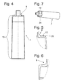
- the Fig. 1 shows a known in construction piston-cylinder unit 1 in the application of a vibration damper.
- a piston rod 5 is guided axially movable.
- a protruding from the cylinder 3 portion of the piston rod 5 is enveloped by a protective tube 7, which is guided axially and radially with its end bottleneck-shaped bottom 9 on a shoulder 11 of the piston rod 5.
Abstract
Description
Die Erfindung betrifft ein Schutzrohr für ein Kolben-Zylinderaggregat gemäß dem Oberbegriff von Patentanspruch 1.The invention relates to a protective tube for a piston-cylinder unit according to the preamble of
Eine Kolbenstange eines Kolben-Zylinderaggregates stellt ein Bauteil dar, dessen Oberfläche unbedingt gegen Schmutz geschützt werden muss, damit eine einen Zylinder verschließende Dichtung nicht durch feine Partikel im Schmutz zerstört wird.A piston rod of a piston-cylinder unit represents a component whose surface must be absolutely protected against dirt, so that a cylinder closing seal is not destroyed by fine particles in the dirt.
Aus Gewichtsgründen haben sich Schutzrohre aus Kunststoff durchgesetzt. Das Schutzrohr verfügt über einen Boden, der sich vielfach auf einem Absatz der Kolbenstange abstützt. Häufig wird der Boden als metallische kreisringförmige Scheibe hergestellt, die mit einem Kunststoffrohr eine Formschlussverbindung eingeht. Der metallische Boden sorgt für eine gute Formstabilität des Kunststoffrohres, verteuert jedoch das Schutzrohr erheblich. In diesem Zusammenhang wird auf die
Die gattungsbildende
Ergänzend wäre noch die
Aufgabe der vorliegenden Erfindung ist es, ein Schutzrohr für ein Kolben-Zylinderaggregat zu realisieren, das vollständig aus Kunststoff besteht und hinsichtlich der Formstabilität optimiert ist.Object of the present invention is to realize a protective tube for a piston-cylinder unit, which consists entirely of plastic and is optimized in terms of dimensional stability.
Erfindungsgemäß wird die Aufgabe dadurch gelöst, dass ein konischer Flächenbereich des flaschenhalsförmigen Bodens ausgehend von seinem äußeren Rand nach radial innen eine zunehmende Materialanhäufung aufweist.According to the invention the object is achieved in that a conical surface region of the bottle neck bottom starting from its outer edge radially inward has an increasing accumulation of material.
Der im Hinblick auf eine Biegebelastung verstärkte Boden sorgt dafür, dass auch bei einer Radialbelastung des Schutzrohres keine kritische Formabweichung auftritt. Dieses Betriebsverhalten erleichtert die Verwendung eines einteiligen Schutzrohres, das, wie bereits erwähnt, einen deutlichen Kostenvorteil im Vergleich zu einer mehrteiligen Lösung aufweist.The reinforced bottom in view of a bending load ensures that even with a radial load of the protective tube no critical shape deviation occurs. This performance facilitates the use of a one-piece protective tube, which, as already mentioned, has a significant cost advantage compared to a multi-part solution.
Bei einer ersten Variante ist vorgesehen, dass die Wandstärke des Bodens nach radial innen zunimmt. Dabei verläuft die Innenseite rechtwinklig zur Kolbenstangenlängsachse.In a first variant it is provided that the wall thickness of the floor increases radially inward. The inside runs at right angles to the piston rod longitudinal axis.
Zusätzlich kann die Wandstärke des Rohrkörpers in Richtung des Bodens zunehmen. Gerade am Übergangsbereich vom Boden zum Rohrkörper stellt sich mit diesem technischen Detail eine deutliche Stabilisierung des Schutzrohres gegen Biegekräfte ein.In addition, the wall thickness of the tubular body in the direction of the soil increase. Especially at the transition region from the bottom to the tubular body, a clear stabilization of the protective tube against bending forces arises with this technical detail.
Je nach Bauraumvorgaben für das Kolben-Zylinderaggregat kann entweder der Innendurchmesser des Rohrkörpers in Richtung des Bodens abnehmen und/oder der Außendurchmesser des Rohrkörpers in Richtung des Bodens zunehmen.Depending on the installation space specifications for the piston-cylinder unit, either the inner diameter of the tubular body can decrease in the direction of the floor and / or the outer diameter of the tubular body can increase in the direction of the floor.
Als ebenfalls sehr vorteilhaft hat es sich herausgestellt, wenn der Flächenbereich des Bodens eine Rippenstruktur aufweist. Trotz vergleichsweise geringerem Materialaufwand und damit Masse wird eine sehr große Gestaltfestigkeit erreicht.It has also turned out to be very advantageous if the area of the bottom has a ribbed structure. Despite comparatively lower material costs and thus mass a very high structural strength is achieved.
Auch der Außendurchmesser des Rohrkörpers kann Rippen aufweisen, die in Richtung des Bodens verlaufen. Die Rippen im Rohrkörper müssen nicht über die gesamte Rohrkörperlänge ausgeführt sein. Besonders relevant ist ein Bereich, der unmittelbar am Boden angrenzt.Also, the outer diameter of the tubular body may have ribs which extend in the direction of the bottom. The ribs in the tubular body need not be made over the entire pipe body length. Particularly relevant is an area immediately adjacent to the ground.
Im Hinblick auf eine gute Entformbarkeit des Schutzrohres gehen die Rippen am Außendurchmesser des Rohrkörpers in die Rippenstruktur des Bodens über.In view of a good demolding of the protective tube, the ribs on the outer diameter of the tubular body go into the ribbed structure of the soil.
Bei einer weiteren Ausführungsform weist der Rohrkörper eine Nennmaterialstärke auf, die im Stützbereich, der in den Boden übergeht, größer und konstant ausgeführt ist. Diese Variante kann z. B. mit einer Rippenstruktur am Boden und am Rohrkörper versehen sein.In a further embodiment, the tubular body has a nominal material thickness, which is made larger and constant in the support area, which merges into the ground. This variant can z. B. be provided with a rib structure at the bottom and the tubular body.
Anhand der folgenden Figurenbeschreibung soll die Erfindung näher erläutert werden.The invention will be explained in more detail with reference to the following description of the figures.
Es zeigt:
- Fig. 1
- Kolben-Zylinderaggregat in Schnittdarstellung
- Fig. 2
- Schutzrohr aus
Fig. 1 - Fig. 3
- Detailansicht zur
Fig. 2 - Fig. 4 -7
- Alternatiwariante mit Rippenstruktur
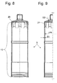
- Fig. 8 u. 9
- Alternativvariante mit konstanter Materialstärke im Bereich des Bodens
- Fig. 1
- Piston-cylinder unit in section
- Fig. 2
- Protective tube off
Fig. 1 - Fig. 3
- Detail view to
Fig. 2 - Fig. 4 -7
- Alternate variant with rib structure
- Fig. 8 u. 9
- Alternative version with constant material thickness in the area of the floor
Die
In der
Der flaschenhalsförmige Boden 9 verfügt über einen Führungsabschnitt 15, der unmittelbar auf der Mantelfläche der Kolbenstange 5 anliegt und für eine radiale Positionierung sorgt. An seinem dem Boden 9 gegenüberliegenden Ende weist der Führungsabschnitt 15 einen nach radial innen weisenden Rand 17 auf, der auf dem Absatz 11 der Kolbenstange 5 anliegt und damit die axiale Positionierung des Schutzrohres zur Kolbenstange 5 übernimmt.The bottle neck bottom 9 has a
Damit auch bei einer radialen Belastung des Schutzrohres 7 an seinem offenen Ende kein Kontakt zwischen dem Schutzrohr 7 und einem äußeren Zylinder 19 unterbleibt, verfügt der Boden 9 ausgehend von seinem äußeren Rand nach radial innen über eine zunehmende Materialanhäufung. In der Variante nach den
Die Zusammenschau der
Eine besonders gewichtsoptimierte Variante eines Schutzrohres 7 ist in den
Die Varianten nach den
Claims (9)
- Protective pipe (7) for a piston/cylinder assembly (1), comprising a pipe body (13) with an end-side bottleneck-shaped bottom (9) which is supported axially and radially at least indirectly on a piston rod (5) of the piston/cylinder assembly (1), characterized in that a surface region of the bottleneck-shaped bottom (9) has an increasing material build-up radially to the inside starting from its outer edge.
- Protective pipe according to Claim 1, characterized in that the wall thickness of the bottom (9) increases radially to the inside.
- Protective pipe according to Claim 1, characterized in that the wall thickness of the pipe body (13) increases in the direction of the bottom (9).
- Protective pipe according to Claim 1 or 3, characterized in that the internal diameter of the pipe body (13) decreases in the direction of the bottom (9).
- Protective pipe according to Claim 1 or 3, characterized in that the external diameter of the pipe body (13) increases in the direction of the bottom (9).
- Protective pipe according to at least one of Claims 1 to 5, characterized in that the surface region of the bottom (9) has a rib structure (29; 31).
- Protective pipe according to at least one of Claims 1 to 6, characterized in that the external diameter of the pipe body (13) has ribs (23) which extend in the direction of the bottom (9).
- Protective pipe according to Claim 6, characterized in that the ribs (23) on the external diameter of the pipe body (13) merge into the rib structure of the bottom (9).
- Protective pipe according to one of Claims 1 to 8, characterized in that the pipe body (13) has a nominal material strength (S1) which is configured to be constant and greater in the end region which merges into the bottom (9).
Applications Claiming Priority (3)
| Application Number | Priority Date | Filing Date | Title |
|---|---|---|---|
| DE102007040455 | 2007-08-28 | ||
| DE102008040984A DE102008040984A1 (en) | 2007-08-28 | 2008-08-05 | Protective tube for a piston-cylinder unit |
| PCT/EP2008/060609 WO2009027228A1 (en) | 2007-08-28 | 2008-08-13 | Protective pipe for a piston/cylinder unit |
Publications (2)
| Publication Number | Publication Date |
|---|---|
| EP2181275A1 EP2181275A1 (en) | 2010-05-05 |
| EP2181275B1 true EP2181275B1 (en) | 2011-07-20 |
Family
ID=40299337
Family Applications (1)
| Application Number | Title | Priority Date | Filing Date |
|---|---|---|---|
| EP08787160A Not-in-force EP2181275B1 (en) | 2007-08-28 | 2008-08-13 | Protective pipe for a piston/cylinder unit |
Country Status (6)
| Country | Link |
|---|---|
| US (1) | US8403116B2 (en) |
| EP (1) | EP2181275B1 (en) |
| CN (1) | CN101784814B (en) |
| AT (1) | ATE517272T1 (en) |
| DE (1) | DE102008040984A1 (en) |
| WO (1) | WO2009027228A1 (en) |
Families Citing this family (7)
| Publication number | Priority date | Publication date | Assignee | Title |
|---|---|---|---|---|
| DE102008040984A1 (en) | 2007-08-28 | 2009-03-05 | Zf Friedrichshafen Ag | Protective tube for a piston-cylinder unit |
| DE102011079986B3 (en) * | 2011-07-28 | 2012-10-18 | Zf Friedrichshafen Ag | Protective tube arrangement for a piston-cylinder unit with a piston rod |
| DE102013101558B4 (en) * | 2013-02-15 | 2019-02-28 | Stabilus Gmbh | Piston-cylinder unit and method of manufacturing a piston-cylinder unit |
| US9757793B2 (en) * | 2013-06-20 | 2017-09-12 | Goodrich Corporation | Reinforced electromechanical actuator housing |
| WO2017090476A1 (en) * | 2015-11-26 | 2017-06-01 | 日立オートモティブシステムズ株式会社 | Cylinder device |
| US10690214B2 (en) * | 2018-08-14 | 2020-06-23 | Daystar Products International, Inc. | Shield for vehicle shock absorber |
| US11111981B2 (en) | 2019-10-17 | 2021-09-07 | DRiV Automotive Inc. | Heat shrinkable dirt shield |
Family Cites Families (24)
| Publication number | Priority date | Publication date | Assignee | Title |
|---|---|---|---|---|
| DE937273C (en) | 1954-07-22 | 1955-12-29 | Hemscheidt Maschf Hermann | Hydraulic vibration damper, especially telescopic damper for motor vehicles |
| DE1951753U (en) | 1966-08-02 | 1966-12-15 | Fichtel & Sachs Ag | PROTECTIVE TUBE FOR TELESCOPIC VIBRATION DAMPERS AND SUSPENSIONS. |
| DE1951754U (en) | 1966-10-07 | 1966-12-15 | Fichtel & Sachs Ag | PROTECTIVE TUBE FOR THE PISTON ROD IN VIBRATION DAMPERS AND SUSPENSIONS WITH TELESCOPIC DESIGN. |
| US3619344A (en) | 1969-08-07 | 1971-11-09 | Du Pont | Oriented foam laminar structures |
| DE1951754C3 (en) | 1969-10-14 | 1981-09-03 | Schwäbische Hüttenwerke GmbH, 7080 Aalen | Device against bridging of silage |
| GB1459530A (en) * | 1973-03-08 | 1976-12-22 | Peddinghaus Carl Ullrich Dr | Resilient fluid device |
| NL161859C (en) | 1975-06-02 | 1980-08-15 | Itt | TELESCOPIC SHOCK ABSORBER WITH DAMPER ADJUSTMENT. |
| US4167991A (en) * | 1977-12-02 | 1979-09-18 | General Motors Corporation | Plastic dust tube for shock absorber |
| US4372429A (en) * | 1980-04-07 | 1983-02-08 | Atwood Vacuum Machine Co. | Pneumatic spring with protective boot |
| DE8228262U1 (en) | 1982-10-08 | 1982-12-02 | August Bilstein GmbH & Co KG, 5828 Ennepetal | Telescopic vibration damper with protective tube |
| DE3735058A1 (en) * | 1987-10-16 | 1989-04-27 | Fichtel & Sachs Ag | PROTECTIVE CAP FOR SHOCK ABSORBER |
| US5074389A (en) * | 1990-01-25 | 1991-12-24 | Bobcat Engineering Corporation | Peripherally valved, temperature-compensated shock absorber |
| EP0707160B1 (en) * | 1994-07-28 | 1998-12-02 | SUSPA COMPART Aktiengesellschaft | Adjustable-length gas spring for chairs, tables etc. |
| EP0831245B2 (en) * | 1996-08-23 | 2003-04-02 | ACE Stossdämpfer GmbH | Industrial shock absorber |
| DE19653393C2 (en) | 1996-12-20 | 2000-09-28 | Mannesmann Sachs Ag | Vibration dampers, in particular for motor vehicles |
| JPH11223235A (en) | 1998-02-05 | 1999-08-17 | Kinugawa Rubber Ind Co Ltd | Bound bumper |
| JP2000074126A (en) | 1998-08-31 | 2000-03-07 | Bridgestone Corp | Bumper rubber |
| JP2001108005A (en) * | 1999-10-12 | 2001-04-20 | Kayaba Ind Co Ltd | Hydraulic shock absorber |
| CN2608759Y (en) * | 2003-03-10 | 2004-03-31 | 沈阳市长城液压机械厂 | Hydraulic shock absorber |
| DE102004003661B4 (en) | 2004-01-24 | 2008-07-24 | Zf Friedrichshafen Ag | Vibration damper with a protective tube |
| JP2006234068A (en) * | 2005-02-25 | 2006-09-07 | Kayaba Ind Co Ltd | Single cylinder-shaped hydraulic damper |
| DE102005031671B4 (en) | 2005-07-05 | 2009-04-09 | Stabilus Gmbh | Infinitely lockable adjusting device |
| CN2929330Y (en) * | 2006-06-26 | 2007-08-01 | 浙江正裕工业有限公司 | Pneumatic self locking shock damper |
| DE102008040984A1 (en) | 2007-08-28 | 2009-03-05 | Zf Friedrichshafen Ag | Protective tube for a piston-cylinder unit |
-
2008
- 2008-08-05 DE DE102008040984A patent/DE102008040984A1/en not_active Withdrawn
- 2008-08-13 WO PCT/EP2008/060609 patent/WO2009027228A1/en active Application Filing
- 2008-08-13 CN CN2008801051520A patent/CN101784814B/en not_active Expired - Fee Related
- 2008-08-13 EP EP08787160A patent/EP2181275B1/en not_active Not-in-force
- 2008-08-13 AT AT08787160T patent/ATE517272T1/en active
- 2008-08-13 US US12/675,489 patent/US8403116B2/en not_active Expired - Fee Related
Also Published As
| Publication number | Publication date |
|---|---|
| CN101784814B (en) | 2011-09-07 |
| ATE517272T1 (en) | 2011-08-15 |
| CN101784814A (en) | 2010-07-21 |
| EP2181275A1 (en) | 2010-05-05 |
| US8403116B2 (en) | 2013-03-26 |
| US20100213655A1 (en) | 2010-08-26 |
| DE102008040984A1 (en) | 2009-03-05 |
| WO2009027228A1 (en) | 2009-03-05 |
Similar Documents
| Publication | Publication Date | Title |
|---|---|---|
| EP2181275B1 (en) | Protective pipe for a piston/cylinder unit | |
| EP1789697B1 (en) | Elastomer bearing | |
| DE102012014318B4 (en) | Spring function component for a hydroelastic bearing and hydroelastic bearing | |
| DE10131075B4 (en) | Unit bearing in bush form | |
| DE10063928B4 (en) | Connecting piece for the articulated connection of arranged in the chassis of a motor vehicle components | |
| EP1611367B1 (en) | Hydraulically damping rubber bush bearing for vertical mounting | |
| EP3132156B1 (en) | Assembly for receiving a suspension spring of a suspension strut, and associated spring seat | |
| DE102011050103A1 (en) | Rolling piston for a Luftfederrollbalg | |
| EP3077684A1 (en) | Annular plug coupling, and production method and connection method therefor | |
| EP1586789A1 (en) | Elastic support for a driver's cab | |
| DE102012206458B3 (en) | Piston-cylinder assembly for vibration damper, has casing body comprising bottom that directs operating pressure of cylinder in direction of stopper body, where stopper body forms annular space with outer lateral surface of cylinder | |
| DE19919863A1 (en) | Rubber bearing with radial travel limitation and damping agent channel | |
| EP2090801B1 (en) | Pneumatic spring rollIing bellows | |
| DE102009002891A1 (en) | Piston-cylinder unit with a connecting element | |
| DE102008000858B4 (en) | Bearing combination with bush bearing | |
| DE10216903B4 (en) | Connection device for an actuating cable to a slave, in particular towing eye | |
| DE10344102B3 (en) | Spring carrier with auxiliary spring for movable components has outer contour with screw profile corresponding to rise of carrier spring | |
| EP1505313A2 (en) | Vibration damper in light weight construction | |
| DE10026970B4 (en) | Elastomer spring and shock absorber arrangement with such an elastomeric spring | |
| DE2934102C2 (en) | Building strut | |
| DE102014225644A1 (en) | Handlebar assembly with a limited with respect to the steering stroke, axially movable handlebar | |
| DE102013200524A1 (en) | Pendulum support for undercarriage, has joint with thrust body, which is made of elastic material, particularly rubber, and which is subjected to shear stress when force is applied on pendulum support in predetermined direction | |
| DE102021211490B4 (en) | Motor vehicle vibration damper with a hydraulic end stop | |
| EP1571366B1 (en) | Elastic support | |
| DE4300490C2 (en) | Connector for concrete construction and elevation for concrete construction made using this connector |
Legal Events
| Date | Code | Title | Description |
|---|---|---|---|
| PUAI | Public reference made under article 153(3) epc to a published international application that has entered the european phase |
Free format text: ORIGINAL CODE: 0009012 |
|
| 17P | Request for examination filed |
Effective date: 20100208 |
|
| AK | Designated contracting states |
Kind code of ref document: A1 Designated state(s): AT BE BG CH CY CZ DE DK EE ES FI FR GB GR HR HU IE IS IT LI LT LU LV MC MT NL NO PL PT RO SE SI SK TR |
|
| AX | Request for extension of the european patent |
Extension state: AL BA MK RS |
|
| DAX | Request for extension of the european patent (deleted) | ||
| GRAP | Despatch of communication of intention to grant a patent |
Free format text: ORIGINAL CODE: EPIDOSNIGR1 |
|
| GRAS | Grant fee paid |
Free format text: ORIGINAL CODE: EPIDOSNIGR3 |
|
| GRAA | (expected) grant |
Free format text: ORIGINAL CODE: 0009210 |
|
| AK | Designated contracting states |
Kind code of ref document: B1 Designated state(s): AT BE BG CH CY CZ DE DK EE ES FI FR GB GR HR HU IE IS IT LI LT LU LV MC MT NL NO PL PT RO SE SI SK TR |
|
| REG | Reference to a national code |
Ref country code: GB Ref legal event code: FG4D Free format text: NOT ENGLISH |
|
| REG | Reference to a national code |
Ref country code: CH Ref legal event code: EP |
|
| REG | Reference to a national code |
Ref country code: DE Ref legal event code: R096 Ref document number: 502008004268 Country of ref document: DE Effective date: 20110922 |
|
| REG | Reference to a national code |
Ref country code: NL Ref legal event code: VDEP Effective date: 20110720 |
|
| PG25 | Lapsed in a contracting state [announced via postgrant information from national office to epo] |
Ref country code: MT Free format text: LAPSE BECAUSE OF FAILURE TO SUBMIT A TRANSLATION OF THE DESCRIPTION OR TO PAY THE FEE WITHIN THE PRESCRIBED TIME-LIMIT Effective date: 20110720 |
|
| PG25 | Lapsed in a contracting state [announced via postgrant information from national office to epo] |
Ref country code: SE Free format text: LAPSE BECAUSE OF FAILURE TO SUBMIT A TRANSLATION OF THE DESCRIPTION OR TO PAY THE FEE WITHIN THE PRESCRIBED TIME-LIMIT Effective date: 20110720 Ref country code: NL Free format text: LAPSE BECAUSE OF FAILURE TO SUBMIT A TRANSLATION OF THE DESCRIPTION OR TO PAY THE FEE WITHIN THE PRESCRIBED TIME-LIMIT Effective date: 20110720 Ref country code: LT Free format text: LAPSE BECAUSE OF FAILURE TO SUBMIT A TRANSLATION OF THE DESCRIPTION OR TO PAY THE FEE WITHIN THE PRESCRIBED TIME-LIMIT Effective date: 20110720 Ref country code: NO Free format text: LAPSE BECAUSE OF FAILURE TO SUBMIT A TRANSLATION OF THE DESCRIPTION OR TO PAY THE FEE WITHIN THE PRESCRIBED TIME-LIMIT Effective date: 20111020 Ref country code: FI Free format text: LAPSE BECAUSE OF FAILURE TO SUBMIT A TRANSLATION OF THE DESCRIPTION OR TO PAY THE FEE WITHIN THE PRESCRIBED TIME-LIMIT Effective date: 20110720 Ref country code: IS Free format text: LAPSE BECAUSE OF FAILURE TO SUBMIT A TRANSLATION OF THE DESCRIPTION OR TO PAY THE FEE WITHIN THE PRESCRIBED TIME-LIMIT Effective date: 20111120 Ref country code: PT Free format text: LAPSE BECAUSE OF FAILURE TO SUBMIT A TRANSLATION OF THE DESCRIPTION OR TO PAY THE FEE WITHIN THE PRESCRIBED TIME-LIMIT Effective date: 20111121 Ref country code: HR Free format text: LAPSE BECAUSE OF FAILURE TO SUBMIT A TRANSLATION OF THE DESCRIPTION OR TO PAY THE FEE WITHIN THE PRESCRIBED TIME-LIMIT Effective date: 20110720 |
|
| REG | Reference to a national code |
Ref country code: IE Ref legal event code: FD4D |
|
| BERE | Be: lapsed |
Owner name: ZF FRIEDRICHSHAFEN A.G. Effective date: 20110831 |
|
| PG25 | Lapsed in a contracting state [announced via postgrant information from national office to epo] |
Ref country code: SI Free format text: LAPSE BECAUSE OF FAILURE TO SUBMIT A TRANSLATION OF THE DESCRIPTION OR TO PAY THE FEE WITHIN THE PRESCRIBED TIME-LIMIT Effective date: 20110720 Ref country code: PL Free format text: LAPSE BECAUSE OF FAILURE TO SUBMIT A TRANSLATION OF THE DESCRIPTION OR TO PAY THE FEE WITHIN THE PRESCRIBED TIME-LIMIT Effective date: 20110720 Ref country code: CY Free format text: LAPSE BECAUSE OF FAILURE TO SUBMIT A TRANSLATION OF THE DESCRIPTION OR TO PAY THE FEE WITHIN THE PRESCRIBED TIME-LIMIT Effective date: 20110720 Ref country code: GR Free format text: LAPSE BECAUSE OF FAILURE TO SUBMIT A TRANSLATION OF THE DESCRIPTION OR TO PAY THE FEE WITHIN THE PRESCRIBED TIME-LIMIT Effective date: 20111021 Ref country code: LV Free format text: LAPSE BECAUSE OF FAILURE TO SUBMIT A TRANSLATION OF THE DESCRIPTION OR TO PAY THE FEE WITHIN THE PRESCRIBED TIME-LIMIT Effective date: 20110720 |
|
| PG25 | Lapsed in a contracting state [announced via postgrant information from national office to epo] |
Ref country code: MC Free format text: LAPSE BECAUSE OF NON-PAYMENT OF DUE FEES Effective date: 20110831 |
|
| PG25 | Lapsed in a contracting state [announced via postgrant information from national office to epo] |
Ref country code: IE Free format text: LAPSE BECAUSE OF FAILURE TO SUBMIT A TRANSLATION OF THE DESCRIPTION OR TO PAY THE FEE WITHIN THE PRESCRIBED TIME-LIMIT Effective date: 20110720 Ref country code: SK Free format text: LAPSE BECAUSE OF FAILURE TO SUBMIT A TRANSLATION OF THE DESCRIPTION OR TO PAY THE FEE WITHIN THE PRESCRIBED TIME-LIMIT Effective date: 20110720 Ref country code: CZ Free format text: LAPSE BECAUSE OF FAILURE TO SUBMIT A TRANSLATION OF THE DESCRIPTION OR TO PAY THE FEE WITHIN THE PRESCRIBED TIME-LIMIT Effective date: 20110720 |
|
| PLBE | No opposition filed within time limit |
Free format text: ORIGINAL CODE: 0009261 |
|
| STAA | Information on the status of an ep patent application or granted ep patent |
Free format text: STATUS: NO OPPOSITION FILED WITHIN TIME LIMIT |
|
| PG25 | Lapsed in a contracting state [announced via postgrant information from national office to epo] |
Ref country code: EE Free format text: LAPSE BECAUSE OF FAILURE TO SUBMIT A TRANSLATION OF THE DESCRIPTION OR TO PAY THE FEE WITHIN THE PRESCRIBED TIME-LIMIT Effective date: 20110720 Ref country code: BE Free format text: LAPSE BECAUSE OF NON-PAYMENT OF DUE FEES Effective date: 20110831 Ref country code: IT Free format text: LAPSE BECAUSE OF FAILURE TO SUBMIT A TRANSLATION OF THE DESCRIPTION OR TO PAY THE FEE WITHIN THE PRESCRIBED TIME-LIMIT Effective date: 20110720 Ref country code: RO Free format text: LAPSE BECAUSE OF FAILURE TO SUBMIT A TRANSLATION OF THE DESCRIPTION OR TO PAY THE FEE WITHIN THE PRESCRIBED TIME-LIMIT Effective date: 20110720 |
|
| 26N | No opposition filed |
Effective date: 20120423 |
|
| PG25 | Lapsed in a contracting state [announced via postgrant information from national office to epo] |
Ref country code: DK Free format text: LAPSE BECAUSE OF FAILURE TO SUBMIT A TRANSLATION OF THE DESCRIPTION OR TO PAY THE FEE WITHIN THE PRESCRIBED TIME-LIMIT Effective date: 20110720 |
|
| REG | Reference to a national code |
Ref country code: DE Ref legal event code: R097 Ref document number: 502008004268 Country of ref document: DE Effective date: 20120423 |
|
| REG | Reference to a national code |
Ref country code: CH Ref legal event code: PL |
|
| GBPC | Gb: european patent ceased through non-payment of renewal fee |
Effective date: 20120813 |
|
| PG25 | Lapsed in a contracting state [announced via postgrant information from national office to epo] |
Ref country code: LI Free format text: LAPSE BECAUSE OF NON-PAYMENT OF DUE FEES Effective date: 20120831 Ref country code: CH Free format text: LAPSE BECAUSE OF NON-PAYMENT OF DUE FEES Effective date: 20120831 Ref country code: ES Free format text: LAPSE BECAUSE OF FAILURE TO SUBMIT A TRANSLATION OF THE DESCRIPTION OR TO PAY THE FEE WITHIN THE PRESCRIBED TIME-LIMIT Effective date: 20111031 |
|
| PG25 | Lapsed in a contracting state [announced via postgrant information from national office to epo] |
Ref country code: LU Free format text: LAPSE BECAUSE OF NON-PAYMENT OF DUE FEES Effective date: 20110813 |
|
| PG25 | Lapsed in a contracting state [announced via postgrant information from national office to epo] |
Ref country code: BG Free format text: LAPSE BECAUSE OF FAILURE TO SUBMIT A TRANSLATION OF THE DESCRIPTION OR TO PAY THE FEE WITHIN THE PRESCRIBED TIME-LIMIT Effective date: 20111020 |
|
| PG25 | Lapsed in a contracting state [announced via postgrant information from national office to epo] |
Ref country code: GB Free format text: LAPSE BECAUSE OF NON-PAYMENT OF DUE FEES Effective date: 20120813 |
|
| PG25 | Lapsed in a contracting state [announced via postgrant information from national office to epo] |
Ref country code: TR Free format text: LAPSE BECAUSE OF FAILURE TO SUBMIT A TRANSLATION OF THE DESCRIPTION OR TO PAY THE FEE WITHIN THE PRESCRIBED TIME-LIMIT Effective date: 20110720 |
|
| PG25 | Lapsed in a contracting state [announced via postgrant information from national office to epo] |
Ref country code: HU Free format text: LAPSE BECAUSE OF FAILURE TO SUBMIT A TRANSLATION OF THE DESCRIPTION OR TO PAY THE FEE WITHIN THE PRESCRIBED TIME-LIMIT Effective date: 20110720 |
|
| PGFP | Annual fee paid to national office [announced via postgrant information from national office to epo] |
Ref country code: FR Payment date: 20130808 Year of fee payment: 6 |
|
| REG | Reference to a national code |
Ref country code: AT Ref legal event code: MM01 Ref document number: 517272 Country of ref document: AT Kind code of ref document: T Effective date: 20130813 |
|
| PG25 | Lapsed in a contracting state [announced via postgrant information from national office to epo] |
Ref country code: AT Free format text: LAPSE BECAUSE OF NON-PAYMENT OF DUE FEES Effective date: 20130813 |
|
| REG | Reference to a national code |
Ref country code: FR Ref legal event code: ST Effective date: 20150430 |
|
| PG25 | Lapsed in a contracting state [announced via postgrant information from national office to epo] |
Ref country code: FR Free format text: LAPSE BECAUSE OF NON-PAYMENT OF DUE FEES Effective date: 20140901 |
|
| PGFP | Annual fee paid to national office [announced via postgrant information from national office to epo] |
Ref country code: DE Payment date: 20180731 Year of fee payment: 11 |
|
| REG | Reference to a national code |
Ref country code: DE Ref legal event code: R119 Ref document number: 502008004268 Country of ref document: DE |
|
| PG25 | Lapsed in a contracting state [announced via postgrant information from national office to epo] |
Ref country code: DE Free format text: LAPSE BECAUSE OF NON-PAYMENT OF DUE FEES Effective date: 20200303 |