EP2180544A1 - Motorcycle - Google Patents
Motorcycle Download PDFInfo
- Publication number
- EP2180544A1 EP2180544A1 EP20090013386 EP09013386A EP2180544A1 EP 2180544 A1 EP2180544 A1 EP 2180544A1 EP 20090013386 EP20090013386 EP 20090013386 EP 09013386 A EP09013386 A EP 09013386A EP 2180544 A1 EP2180544 A1 EP 2180544A1
- Authority
- EP
- European Patent Office
- Prior art keywords
- storage
- partition plate
- storage room
- frame
- gps unit
- Prior art date
- Legal status (The legal status is an assumption and is not a legal conclusion. Google has not performed a legal analysis and makes no representation as to the accuracy of the status listed.)
- Granted
Links
Images



Classifications
-
- B—PERFORMING OPERATIONS; TRANSPORTING
- B60—VEHICLES IN GENERAL
- B60R—VEHICLES, VEHICLE FITTINGS, OR VEHICLE PARTS, NOT OTHERWISE PROVIDED FOR
- B60R25/00—Fittings or systems for preventing or indicating unauthorised use or theft of vehicles
- B60R25/10—Fittings or systems for preventing or indicating unauthorised use or theft of vehicles actuating a signalling device
- B60R25/102—Fittings or systems for preventing or indicating unauthorised use or theft of vehicles actuating a signalling device a signal being sent to a remote location, e.g. a radio signal being transmitted to a police station, a security company or the owner
-
- B—PERFORMING OPERATIONS; TRANSPORTING
- B62—LAND VEHICLES FOR TRAVELLING OTHERWISE THAN ON RAILS
- B62H—CYCLE STANDS; SUPPORTS OR HOLDERS FOR PARKING OR STORING CYCLES; APPLIANCES PREVENTING OR INDICATING UNAUTHORIZED USE OR THEFT OF CYCLES; LOCKS INTEGRAL WITH CYCLES; DEVICES FOR LEARNING TO RIDE CYCLES
- B62H5/00—Appliances preventing or indicating unauthorised use or theft of cycles; Locks integral with cycles
-
- B—PERFORMING OPERATIONS; TRANSPORTING
- B62—LAND VEHICLES FOR TRAVELLING OTHERWISE THAN ON RAILS
- B62J—CYCLE SADDLES OR SEATS; AUXILIARY DEVICES OR ACCESSORIES SPECIALLY ADAPTED TO CYCLES AND NOT OTHERWISE PROVIDED FOR, e.g. ARTICLE CARRIERS OR CYCLE PROTECTORS
- B62J9/00—Containers specially adapted for cycles, e.g. panniers or saddle bags
- B62J9/10—Containers specially adapted for cycles, e.g. panniers or saddle bags integrated with the cycle
- B62J9/14—Containers specially adapted for cycles, e.g. panniers or saddle bags integrated with the cycle under the saddle
-
- G—PHYSICS
- G01—MEASURING; TESTING
- G01S—RADIO DIRECTION-FINDING; RADIO NAVIGATION; DETERMINING DISTANCE OR VELOCITY BY USE OF RADIO WAVES; LOCATING OR PRESENCE-DETECTING BY USE OF THE REFLECTION OR RERADIATION OF RADIO WAVES; ANALOGOUS ARRANGEMENTS USING OTHER WAVES
- G01S19/00—Satellite radio beacon positioning systems; Determining position, velocity or attitude using signals transmitted by such systems
- G01S19/01—Satellite radio beacon positioning systems transmitting time-stamped messages, e.g. GPS [Global Positioning System], GLONASS [Global Orbiting Navigation Satellite System] or GALILEO
- G01S19/13—Receivers
- G01S19/14—Receivers specially adapted for specific applications
- G01S19/16—Anti-theft; Abduction
-
- H—ELECTRICITY
- H01—ELECTRIC ELEMENTS
- H01Q—ANTENNAS, i.e. RADIO AERIALS
- H01Q1/00—Details of, or arrangements associated with, antennas
- H01Q1/27—Adaptation for use in or on movable bodies
- H01Q1/32—Adaptation for use in or on road or rail vehicles
- H01Q1/325—Adaptation for use in or on road or rail vehicles characterised by the location of the antenna on the vehicle
- H01Q1/3291—Adaptation for use in or on road or rail vehicles characterised by the location of the antenna on the vehicle mounted in or on other locations inside the vehicle or vehicle body
-
- B—PERFORMING OPERATIONS; TRANSPORTING
- B60—VEHICLES IN GENERAL
- B60R—VEHICLES, VEHICLE FITTINGS, OR VEHICLE PARTS, NOT OTHERWISE PROVIDED FOR
- B60R2325/00—Indexing scheme relating to vehicle anti-theft devices
- B60R2325/30—Vehicles applying the vehicle anti-theft devices
- B60R2325/306—Motorcycles
-
- B—PERFORMING OPERATIONS; TRANSPORTING
- B62—LAND VEHICLES FOR TRAVELLING OTHERWISE THAN ON RAILS
- B62K—CYCLES; CYCLE FRAMES; CYCLE STEERING DEVICES; RIDER-OPERATED TERMINAL CONTROLS SPECIALLY ADAPTED FOR CYCLES; CYCLE AXLE SUSPENSIONS; CYCLE SIDECARS, FORECARS, OR THE LIKE
- B62K2202/00—Motorised scooters
Definitions
- the present invention relates to a motorcycle and more particularly to a motorcycle equipped with a GPS unit that transmits positional information.
- JP 2002-362448 A discloses an arrangement in which a motorcycle is provided with a device arranged to inform about a theft by radio transmission. More specifically, an anti-theft device that informs about the location of a stolen vehicle using a positioning system such as GPS (Global Positioning System) and PHS (Personal Handy-phone System) is provided in a helmet storing box for which the seat that can be locked serves as an operable lid. In this way, the device can be provided in a place hardly discoverable by a stranger without unlocking the lid while the owner can easily check the indicator by opening the lid, and rainwater can be prevented from coming in.
- the anti-theft device is stored in a case and then provided, so that the device can be even more vibration-proof and waterproof, and a window is provided to allow the indicator to be visually recognized.
- An anti-theft device is preferably provided in a hardly discoverable place. If a criminal who stolen a motorcycle finds the anti-theft device and removes it from the motorcycle, the owner can no longer track the location of the stolen vehicle.
- an anti-theft device is attached at a corner of a small item storage formed under a rear seat.
- the rear seat is locked, anybody other than the owner cannot look into the small item storage. Therefore, the anti-theft device is hardly discovered.
- an anti-theft device is preferably positioned to obtain the highest possible receiving sensitivity.
- the disclosed document does not mention anything about the point.
- a motorcycle comprising a frame, an engine provided under the frame, a seat provided above the frame, a storage box provided in a position higher than the engine and under the seat; and a fuel tank provided behind the storage box, wherein the storage box comprises a storage case with an opening at its upper end, a first storage room provided at an upper part of the storage case, a second storage room provided under the first storage room in the storage case and separated from the first storage room, and a Global Positioning System (GPS) unit including at least an antenna and provided in the second storage room.
- GPS Global Positioning System
- the GPS unit is stored in the second storage room separated from the first storage room such that the GPS cannot easily be discovered. Therefore, a motorcycle including a GPS unit provided in a hardly discoverable position where the receiving sensitivity is not easily degraded can be provided.
- the frame has a front frame extending obliquely downward from a front to a back of the motorcycle and a rear frame extending obliquely upward from the front frame to the back.
- the engine is provided under a rear part of the front frame, and/or the seat is provided above the rear frame.
- the storage box further comprises a first partition plate provided between the first and second storage rooms to separate the first storage room from the second storage room.
- the GPS unit further comprises a GPS receiver configured to calculate positional information based on a GPS signal received by the antenna, and a position transmitter configured to transmit a position signal indicating the positional information calculated by the GPS receiver from the antenna.
- the antenna is provided in a position equal to or higher than the frame, respectively the rear frame.
- the GPS unit has a substantially flat shape and is laid.
- the storage box further comprises a third storage room provided under the second storage room in the storage case and being separated from the first and second storage rooms.
- the storage box further comprises a second partition plate provided between the second and third storage rooms to separate the second storage room from the third storage room, and, preferably, the second partition plate has a through hole, a battery is provided in the third storage room, and a wire passes through the through hole and connects the GPS unit and the battery.
- the first and second partition plates are attached to the storage case in a detachable manner, and, preferably, the GPS unit is attached to the second partition plate.
- the second partition plate further comprises a support member provided upright on a surface of the second partition plate, and, preferably, the GPS unit is supported by the support member and apart from the second partition plate.
- the storage case has a width gradually reduced toward the front
- the GPS unit preferably further comprises a unit case having a side surface provided with a connector to which the wire is connected and storing the antenna, the GPS receiver, and the position transmitter
- the GPS unit is preferably attached to the second partition plate
- the side surface is preferably opposed to an inner side surface of the storage case, a distance between a side surface and an inner side surface of the storage case is reduced toward the front
- the connector is provided more on the rear side than the center of the side surface
- the antenna is provided in an upper part of the unit case.
- the second partition plate is provided in a position substantially equal to or higher than the rear frame.
- Fig. 1 is a functional block diagram showing the structure of the entire anti-theft system.
- the anti-theft system includes a Global Positioning System (GPS) unit 15 provided in the motorcycle, a GPS satellite 101, and a management center 201.
- GPS Global Positioning System
- the GPS unit 15 includes an antenna 35, a GPS receiver 36, and a position transmitter 37.
- the antenna 35 receives GPS signals transmitted from the GPS satellite 101.
- the GPS receiver 36 calculates positional information based on the GPS signals received by the antenna 35.
- the GPS unit 15 is provided in the motorcycle and therefore the GPS receiver 36 produces the positional information of the motorcycle.
- the GPS unit 15 stores the identification information of the motorcycle in a memory that is not shown.
- the position transmitter 37 transmits a position signal indicating positional information and an identification signal indicating identification information from the antenna 35.
- the management center 201 receives the position signal and the identification signal and manages the positional information and the identification information.
- the GPS unit 15 is connected to a CDI (Capacitor Discharge Ignition) unit 26, a horn controller 56 and a lamp controller 57.
- the GPS unit 15 controls the ignition plug 38 of the engine through the CDI unit 26.
- the GPS unit 15 further activates a horn or flashes a lamp through the horn controller 56 and the lamp controller 57.
- the rider of the motorcycle informs the management center 201 of the fact.
- the management center 201 keep receiving position signals and identification signals transmitted from the GPS unit 15 of the stolen motorcycle. Therefore, the management center 201 can specify the location of the motorcycle and track down the vehicle.
- the management center 201 controls the stolen motorcycle. More specifically, the management center 201 transmits an alarm command to the GPS unit 15.
- the GPS unit 15 controls the horn controller 56 in response to the alarm command and activates the horn.
- the GPS unit 15 controls the lamp controller 57 in response to the alarm command and flashes the lamp. In this way, people around the motorcycle can be aware that the motorcycle is a stolen vehicle.
- the management center 201 further transmits a stop command to the GPS unit 15.
- the GPS unit 15 responds to the stop command and controls the CDI unit 26 so that the ignition plug 38 is not operated. In this way, the engine is stopped.
- the GPS unit 15 does not have to be connected to the CDI unit 26. In this case, the GPS unit 15 does not control the CDI unit 26.
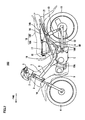
- Fig. 2 is a left side view of the motorcycle 100 facing forward (FWD).
- the motorcycle 100 includes a frame 1, an engine E, a seat 18, a storage box 17, a fuel tank 14, a front wheel 4, and a rear wheel 11.
- the frame 1 is provided in a lower position than the frame of a general saddle type motorcycle.
- the frame 1 is a so-called under bone type frame.
- the frame 1 includes a head pipe 3, a front frame 6, and a pair of rear frames 7.
- the front frame 6 is coupled to the head pipe 3. More specifically, the front frame 6 is coupled to the lower part of the head pipe 3. The front frame 6 extends obliquely downward in the front-back direction from the head pipe 3. The rear frame 7 is coupled to the rear part of the front frame 6. The rear frame 7 extends obliquely upward to the back.
- a reinforcement frame 8 is provided at the rear end of the front frame 6.
- the reinforcement frame 8 is provided under the rear frame 7.
- the reinforcement frame 8 extends obliquely upward to the back.
- the rear end of the reinforcement frame 8 is connected to the rear frame 7 approximately in the center.
- the reinforcement frame 8 supports the rear frame 7.
- the frame 1 is covered with a plurality of body covers 9.
- the rear end of the front frame 6 is positioned behind the front end of the seat 18 when seen in a side view.
- the front end of the rear frame 7 is positioned substantially in the same position as the front end of the seat 18 in the front-back direction when seen in a side view.
- a steering shaft 2 is rotatably inserted to the head pipe 3.
- a handle 5 is fixed to the upper end of the steering shaft 2.
- a pair of front forks 16 is provided under the head pipe 3.
- the front wheel 4 is rotatably attached to the lower end of the front forks 16.
- the engine E is provided under the rear part of the front frame 6.
- the engine E is supported by the front frame. More specifically, the engine E is supported by the frame 6 through engine brackets 10A and 10B.
- the bracket 10B is provided with a pivot shaft 60.
- the rear arm 12 is supported so that it can swing in the vertical direction around the pivot shaft 60.
- the rear wheel 11 is rotatably attached to the rear end of the rear arm 12.
- a shock absorber 13 is provided between the rear end of the rear arm 12 and the rear frames 7.
- the seat 18 is provided above the pair of rear frames 7.
- the seat 18 includes a main seat 18A and a tandem seat 18B adjacent to the rear end of the main seat 18A.
- a rider is seated on the main seat 18A.
- the tandem seat 18B is one step higher than the main seat 18A.
- a tandem rider is seated on the tandem seat 18B.
- the storage box 17 and the fuel tank 14 are provided next to each other in the front-back direction under the seat 18.
- the storage box 17 is positioned above the engine E and under the front part of the seat 18. More specifically, the storage box 17 is provided under the main seat 18A.
- the front end surface of the storage box 17 is provided ahead of the rear end surface of the engine E.
- the fuel tank 14 is provided under the rear part of the seat 18 and behind the storage box 17. More specifically, the fuel tank 14 is provided under the tandem seat 18B.
- the fuel tank 14 is a metal tank and stores fuel to be supplied to the engine E.
- the fuel tank 14 is fixed to the rear frames 7 through brackets that are not shown.
- the fuel tank 14 includes a supply inlet 14A on the upper surface.
- the storage box 17 has an opening at the upper end and stores miscellaneous items or the like belonging to the rider.
- a hinge 19 is provided at the front end of the storage box 17.
- the seat 18 is supported rotatably around the hinge 19 at its tip end. When the seat 18 is rotated around the hinge 19 and lifted upright, the opening of the storage box 17 is exposed. In other words, when the seat 18 is lifted upright, the storage box 17 is opened. When the seat 18 is rotated around the hinge 19 and put back, the storage box 17 is closed.
- a lock device that is no shown in provided at the rear end of the seat 18. The locked seat 18 cannot be rotated and the storage box 17 is not opened.
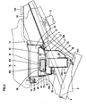
- Fig. 3 is a fragmentary sectional view showing the storage box 17 and its periphery in Fig. 2 being enlarged.
- the storage box 17 is fixed to the pair of rear frames 7.
- Cross bars 50 and 51 are extended between the pair of the rear frames 7.
- the cross bar 51 is provided behind the cross bar 50.
- the front part of the bottom surface of the storage box 17 is fixed to the cross bar 50 and the rear part of the bottom surface of the storage box 17 is fixed to the cross bar 51.
- the lower part of the storage box 17 is held between the pair of rear frames 7.
- the storage box 17 overlaps the pair of rear frames 7 when seen in a side view.
- the upper end of the storage box 17 is positioned above the pair of rear frames 7.
- the lower end of the storage box 17 is positioned under the pair of rear frames 7.
- the upper part of the rear end of the storage box 17 is coupled to the upper part of the tip end of the fuel tank 14 by brackets 21.
- the pair of rear frames 7 extends obliquely upward to the back under the seat 18. Therefore, the space between the bottom of the seat 18 and the pair of rear frames 7 is maximized at the front end of the seat 18 and reduced toward the rear end of the seat 18.
- the storage box 17 is provided under the front part of the seat 18 and the fuel tank 14 is provided under the rear part of the seat 18. Therefore, the storage box 17 can have a larger capacity than the case in which the storage box is provided under the rear part of the seat 18.
- the storage box 17 includes a storage case 20 and partition plates 45 and 29.
- the storage box 17 stores the GPS unit 15.
- the storage box 17 is divided into storage rooms 22 to 24 by the partition plates 45 and 29.
- the partition plate 45 corresponds to a "first partition plate” according to the present teaching .
- the partition plate 29 corresponds to a "second partition plate” according to the present teaching .
- the storage room 24 corresponds to a "first storage room” according to the present teaching.
- the storage room 23 corresponds to a "second storage room” according to the present teaching.
- the storage room 22 corresponds to a "third storage room” according to the present teaching. Accordingly, the first storage room 24 is separated from the second storage room 23.
- the third storage room 22 is separated from at least one of the first and second storage rooms 24, 23, preferably from both of said first and second storage rooms 24, 23.
- the storage case 20 is made of synthetic resin and has an opening at its upper end.
- the storage room 24 is provided above the storage case 20.
- the storage room 23 is provided under the storage room 24.
- the storage room 22 is provided under the storage room 23.
- the partition plate 45 is provided between the storage rooms 24 and 23.
- the partition plate 29 is provided between the storage rooms 23 and 22. In the storage box 17 three storage rooms placed on one another are formed.
- Fig. 4 is an exploded perspective view of the storage box 17. With reference to Fig. 4 , the width of the storage box 17 is gradually narrowed toward the front (FWD) from the back of the vehicle.
- the GPS unit 15 is provided between the partition plates 29 and 45 in the storage case 20.
- the GPS unit 15 has a flat square shape.
- the GPS unit 15 is attached horizontally on the partition plate 29.
- the GPS unit 15 is attached on the partition plate 29 so that the length in the crosswise or front-back direction is greater than the length in the vertical direction.
- the GPS unit 15 is attached on the partition plate 29 so that its area when seen in a top view is larger than the area in a side view.
- the GPS unit 15 is attached on the partition plate 29 so that the receiving range of the built-in antenna is directed upward.
- the storage room 22 stores a battery 16 and electric equipment that is not shown.
- the storage room 23 stores the GPS unit 15.
- the storage room 24 is a small item storage.
- the storage room 24 stores a raincoat, tools and the like.
- the partition plate 45 has an upper surface that extends in the front-back direction.
- the upper surface of the partition plate 45 is substantially flat. More specifically, the bottom surface of the storage room 24 is substantial flat, which is a shape easy to use as a small item storage.
- the inner surface of the storage room 24 is observable. If there is a raised or recessed part at the bottom surface of the storage room 24, it may suggest that there is equipment such as a GPS unit under the storage room 24. If the bottom surface of the storage room 24 is substantially flat, it is hardly noticed that the GPS unit 15 is stored under the storage room 24.
- the storage room 23 stores the GPS unit 15.
- the bottom surface of the storage room 23 corresponds to the upper surface of the partition plate 29.
- the ceiling surface of the storage room 23 corresponds to the lower surface of the partition plate 45.
- Fig. 5 is a plan view of the storage box 17 removed of the partition plate 45 and its periphery.
- a sectional view taken along line III-III in Fig. 5 corresponds to Fig. 3 .
- the GPS unit 15 includes a flat square unit case 39, an antenna 35, a GPS receiver 36 ( Fig. 1 ), and a position transmitter 37 ( Fig. 1 ).
- the unit case 39 stores the antenna 35, the GPS receiver 36, and the position transmitter 37.
- the material of the unit case 39 is for example synthetic resin.
- the antenna 35 is sheet shaped and provided at an upper part in the unit case 39 as shown in Fig. 3 .
- the antenna 35 is provided between the pair of frames 7 when seen in a top view.
- the antenna 35 is provided on the left side of the central axis X-X of the vehicle when seen in a top view.
- the GPS unit 15 further includes a connector 44 provided on a side of the GPS case 39.
- the connector 44 is connected with a connector 40 attached to one end of a wire harness 41.
- the other end of the wire harness 41 is connected to the battery 16 and the electric equipment.
- the GPS unit 15 is connected to the battery 16 and the electric equipment through the wire harness 41.
- the GPS unit 15 is powered from the battery 16 and communicates with the CDI unit 26.
- the GPS unit 15 further includes an auxiliary battery that is not shown in the unit case 39. When no power is supplied from the battery 16, an auxiliary battery is used.
- Fig. 6 is a sectional view taken along line VI-VI in Fig. 5 .
- the GPS unit 15 is adjacent to the battery 16 through the partition plate 29. Since the GPS unit 15 is provided near the battery 16, the wire harness 41 is short.
- a through hole 33 is formed near the rear end of the partition plate 29.
- the wire harness 41 connects the GPS unit 15 and the battery 16 and the electric equipment through the through hole 33. As described above, the GPS unit 15 and the battery 16 are adjacent to each other through the partition plate 29.
- the wire harness 41 is passed through the through hole 33 and the space required for providing the harness 41 can be reduced.
- a guide rib 45 is provided at the rear part of the partition plate 29.
- the tip end of the guide rib 45 is curved.
- the wire harness 41 is curved along the tip end of the guide rib 45 and guided into the through hole 33.
- the guide rib 45 restricts the bending of the wire harness 41.
- An elastic band 42 is wound around the outer surface of the GPS unit 15.
- the elastic band 42 is for example made of rubber.
- the elastic band 42 includes band portions 42A and 42B.
- the band portion 42A is an annular band wrapped around the central parts of a pair of side surfaces of the unit case 39 perpendicular to the side surface provided with the connector 44 and the central parts of the upper and lower surface.
- the antenna 35 is covered with the band portion 42A.
- the band portion 42B connects the upper and lower surfaces of the band portion 42A across the side surface provided with the connector 44.
- the band portion 42B is provided in a position not overlapping the connector 44. More specifically, the band portion 42B is shifted from the center of the width of the band 42A to the opposite side to the connector 44.
- Attachment portions 43 are formed at the outer surfaces of the parts of the band portion 42A that overlap the side surfaces of the unit case 39.
- the attachment portions 43 each have a square shape and a through hole penetrating in the height-wise direction.
- plate shaped support members 34A and 34B are provided upright on the surface of the partition plate 29.
- the support member 34A is provided upright near the front edge of the partition plate 29 on the central axis X-X.
- the support member 34B is provided upright behind the support member 34A and on the left side of the central axis X-X.
- the support members 34A and 34B are inserted into the through holes in the attachment parts 43. In this way, the GPS unit 15 is elastically fixed on the partition plate 29.
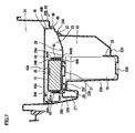
- Fig. 7 is a sectional view taken along line VII-VII in Fig. 5 .
- the support member 34A includes an insert portion 341A and a support portion 342A.
- the support portion 342A is adjacent to the lower end of the insert portion 341A.
- the insert portion 341A and the support portion 342A are integrally formed.
- the support portion 342A is thicker than the insert portion 341A. Therefore, the support member 34A has a stepped shape.
- the support portion 34B includes an insert portion 341 B and a support portion 342B.
- the insert portion 341A is inserted into the through hole of the attachment portion 34.
- the support portion 341 B is thick and therefore cannot be inserted into the through hole of the attachment portion 34. Therefore, the elastic band 42 is not in contact with the upper surface of the partition plate 29 and a gap 500 is formed between the GPS unit 15 and the partition plate 29.
- the GPS unit 15 is supported by the support members 34A and 34B as it is held up. Therefore, vibration from the motorcycle 100 is not easily transmitted to the GPS unit 15.
- the antenna 35 receives GPS signals transmitted from the GPS satellite 101. In order to improve the receiving sensitivity, the antenna 35 is directed upward. It is preferable that less interfering objects that lower the receiving sensitivity are provided above the antenna 35. It is therefore preferable that less metal automotive body parts that interfere with GPS signals are provided above the antenna 35.
- the GPS unit 15 is provided above the engine E and in front of the fuel tank 14. Therefore, degradation in the receiving sensitivity caused by the engine E and the fuel tank 14 is reduced.
- the antenna 35 is provided in a position higher than the metal rear frames 7.
- the receiving sensitivity of the antenna 35 is affected not only by the engine E and the fuel tank 14 but also by the rear frames 7.
- the antenna 35 is provided in a position substantially equal to or higher than the rear frames 7, interference by the rear frames 7 is less likely. Therefore, the receiving sensitivity can be improved.
- the motorcycle 100 receives external force in the vertical direction from the road surface through the front wheel 4 and the rear wheel 11. Therefore, the front part and the rear part of the frame 1 are moved up and down. As shown in Fig. 3 , the GPS unit 15 is provided near the center of the motorcycle 100. Therefore, the GPS unit 15 is less affected by the vertical movement generated in front of and behind the frame 1 and the displacement of the antenna 35 is reduced. Therefore, the antenna receiving sensitivity is improved.
- the side surface of the unit case 39 provided with the connector 44 is opposed to the inner side surface of the storage case 20.
- the distance between the side surface of the unit case 39 provided with the connector 44 and the inner side surface of the storage case 20 is reduced toward the front side from the rear side.
- the connector 44 is provided more on the rear side than the center of the side surface of the unit case 39.
- the antenna 35 is provided in the upper part of the unit case 39.
- the connector 44 is provided more on the front side than the center of the side surface of the unit case 39.
- the distance between the side surface of the unit case 39 provided with the connector 44 and the inner side surface of the storage case 20 is narrowed toward the front, and therefore the space used to connect the connector 40 to the connector 44 is reduced. Since it is not easy to connect the connector 40 to the connector 44, the operator realizes that the GPS unit 15 has been attached upside down. Therefore, the possibility of attaching the GPS unit 15 upside down can be reduced.
- the storage room 22 is provided at the lowermost part of the storage box 17.
- the storage room 22 stores the battery 16 and electric equipment that is not shown.
- the electric equipment includes components such as the CDI unit 26, a fuse box, and a rela0y box.
- a partition plate 25 is provided upright at the bottom surface of the storage room 22.
- the storage room 22 is divided into a front space and a rear space by the partition plate 25.
- the battery 16 is stored in the front space and the electric equipment is stored in the rear space.
- the storage room 22 is held between the pair of the rear frames 7.
- the bottom of the storage room 22 includes three bottom portions 22A to 22C in the direction from the front to the back.
- the bottom portion 22A is formed at the front part and the right and left side parts of the storage room 22.
- the bottom portion 22B is formed on the inner side of the bottom portion 22A. More specifically, the bottom portion 22B is surrounded by the bottom portion 22A.
- the bottom portion 22C is provided behind the bottom portion 22B.
- the bottom portions 22A to 22C are integrally formed.
- the bottom portions 22A to 22C have different heights.
- the bottom portion 22A is higher than the bottom portions 22B and 22C.
- the bottom portion 22C is higher than the bottom portion 22B.
- the bottom portion 22B is the lowest.
- the bottom portion 22A is fixed to a cross bar 50 by bolts and nuts.
- the rear end of the bottom portion 22A is connected to the upper end of the side wall 22D.
- the front end of the bottom portion 22B is connected to the rear end of the side wall 22D.
- the rear end of the bottom portion 22B is connected to the rear part of the side wall 22E.
- the tip end of the bottom portion 22C is connected to the upper end of the side wall 22E.
- the bottom portion 22A partly has recessed and raised portions.
- a recess 22F is recessed inside the storage room 22.
- the recess 22F is used to stably support the partition plate 29.
- a partition plate 28 is provided upright near the inner side edge of the inner surface of the bottom portion 22A. The partition plate 28 is used to stably support the partition plate 29.
- the partition plate 29 is provided between the storage rooms 23 and 22.
- the material of the partition plate 29 is synthetic resin.
- the partition plate 29 includes a floor plate 29A and a plate shaped skirt 29B.
- the skirt 29B is pendent from the circumferential edge of the floor plate 29A.
- the floor plate 29A has a shape similar to the opening of the storage box 17, and the width of the floor plate 29A is gradually reduced from the back to the front (FWD). As shown in Figs. 6 and 7 , support members 30 and 31 are formed at the back surface of the floor plate 29A.
- the support member 30 is formed at the front of the back surface of the floor plate 29A.
- the support member 30 has a cylindrical shape.
- the support member 31 is formed in the center of the back surface of the floor plate 29A.
- the support member 31 has a square shape.
- the floor plate 29A further includes a plurality of hooks 29C at the rear end.
- the rear wall of the storage case 20 has a plurality of openings 32 corresponding to the hooks 29C.
- the hooks 29C are inserted into the openings 32. In this way, the partition plate 29 is supported by the rear wall of the storage case 20.
- the lower end of the skirt 29B is in contact with the inner surface of the bottom wall portion 22A as shown in Figs. 6 and 7 .
- the support member 30 is in contact with the inner surface of the recess 22F of the bottom wall portion 22A.
- the support member 31 is in contact with the upper surface of the battery 16. Therefore, the floor plate 29A is supported substantially horizontally in a stable manner.
- the hooks 29C, the skirt 29B, and the support members 30 and 31 support the floor plate 29A in a horizontal position.
- the antenna 35 is in a higher position than the rear frames 7. Therefore, degradation in the receiving sensitivity is reduced.
- the floor plate 29A is in a higher position than the rear frames 7.
- the floor plate 29A and the rear frames 7 may be at the same height.
- the floor plate 29A when the floor plate 29A is provided in a position equal to or higher than the rear frames 7, degradation in the receiving sensitivity of the antenna 35 can be reduced. This is because the antenna 35 is provided in a position higher than the rear frames 7.
- the partition plate 45 is provided between the storage rooms 24 and 23.
- the partition plate 45 separates the storage room 24 from the storage room 23.
- the material of the partition plate 45 is synthetic resin.
- the partition plate 45 includes a floor plate 45A and a skirt 46.
- the floor plate 45A has a shape similar to the opening of the storage box 17, and the width of the floor plate 45A is gradually reduced from the back to the front.
- the floor plate 45A is flat.
- the skirt 46 is plate shaped and pendent from the circumferential edge of the floor plate 45A. As shown in Fig. 7 , a skirt portion 46A of the skirt 46 that is pendent from the front end of the floor plate 45A (hereinafter referred to as “front end skirt portion”) is tapered. More specifically, the tip end of the front end skirt portion 46A is chamfered. A skirt portion 46B pendent from the rear end of the floor plate 45A (hereinafter referred to "rear end skirt portion”) has a plurality of hooks 48 at its tip end.
- the storage case 20 includes a front wall 20C.
- the front wall 20C extends obliquely forward and upward from the front end of the bottom wall 22A.
- the storage case 20 further has a rear wall 20D opposed to the upper part of the front wall 20C, and its rear wall has a plurality of openings 49.
- the tip end of the front end skirt portion 46A is in contact with the inner surface of the upper part of the front wall 20C.
- the hooks 48 are then inserted into the openings 49.
- the partition plate 45 is made of synthetic resin and therefore has a certain degree of elasticity.
- the front skirt portion 46A and the hooks 48 press the inner surface of the storage case 20 that are in contact with them. Therefore, the partition plate 45 is fixed to the storage case 20.
- the floor plate 45A is provided substantially horizontally.
- a side surface portion of the skirt 46 is not in contact with the storage case 20. More specifically, the partition plate 45 is attached to the storage case 20 by the front end skirt portion 46A and the hooks 48. Screw holes that are not shown are provided at the front ends of the partition plates 29 and 45. The partition plates 29 and 45 are fastened together by a single bolt (not shown) inserted into the screw holes. When the bolt is removed and the hooks 29 and 48 are removed from the openings 32 and 49, the partition plates 29 and 45 are removed from the storage case 20.
- the partition plates 29 and 45 are attached to the storage case 20 in a detachable manner.
- the GPS unit 15 attached to the partition plate 29 can be removed easily from the storage case 20 once the partition plate 29 is removed.
- the storage room 24 is formed at the uppermost part of the storage case 20.
- the storage room 24 is separated from the storage room 23 by the partition plate 45.
- the opening of the storage room 24 is exposed. Then, a rider can place his/her items and the like in the storage room.
- the upper surface of the floor plate 45A is flat. Therefore, the floor of the storage room 24 is substantially flat. If the floor of the storage room 24 has irregularities, one might suspect the presence of the anti-theft device hidden under the floor of the storage room 24. However, the floor of the storage room 24 is flat and it is hard to discern the presence of the hidden anti-theft device in the place.
- the motorcycle according to the present teaching is not limited to the above-described preferred embodiment.
- the partition plate 29 does not have to be provided.
- the GPS unit 15 is fixed to the upper surface of the battery 16.
- the GPS unit 15 may be fixed to the back surface of the floor plate 45A of the partition plate 45.
- the storage room under the partition plate 45 corresponds to the "second storage room” according to the present teaching.
- the unit case 39 may have a shape other than the flat square shape. Note however that the antenna 35 is preferably provided at the upper part in the unit case 39. In this way, the GPS antenna 35 can have improved receiving sensitivity.
- rear frame 7 Only one rear frames 7 may be provided.
- the rear frame 7 seen from above extends on the same axis as that of the front frame 6.
- the frame is not limited to the arrangement according to the preferred embodiment described above.
- the frame needs only include a front frame arranged to extend obliquely downward from the front to the back and a rear frame arranged to extend obliquely upward from the front frame to the back.
- the head pipe and the front frame may be formed integrally or the front frame and the rear frame may be formed integrally.
- the front frame may extend obliquely downward at a plurality of angles or the rear frame may extend obliquely upward at a plurality of angles.
- the seat is not limited to the arrangement in the above described preferred embodiment.
- the seat needs only be provided above the rear frame.
- the main seat and the tandem seat may be provided flush with no step between them. Only the main seat may be provided without providing the tandem seat.
- the storage box may extend under both the main seat and the tandem seat.
- the fuel tank may extend under both the main seat and the tandem seat.
- the storage box may be provided only under the main seat, and the fuel tank may be provided only under the tandem seat.
- the guide rib is not limited to the arrangement in the above-described preferred embodiment.
- the guide rib may be only a part of the preferred embodiment or the guide rib does not have to be provided.
- the motorcycle preferably includes a front frame arranged to extend obliquely downward from the front to the back, a rear frame arranged to extend obliquely upward from the front frame to the back, an engine provided under the rear part of the front frame, a seat provided above the rear frame, a storage box provided in a position higher than the engine and under the seat, and a fuel tank provided behind the storage box.
- the storage box includes a storage case having an opening at the upper end, a first storage room provided in the upper part of the storage case, a second storage room provided under the first storage room in the storage case, a first partition plate provided between the first and second storage rooms, and a GPS (Global Positioning System) unit provided in the second storage room.
- the GPS unit includes an antenna, a GPS receiver that calculates positional information based on GPS signals received by the antenna, and a position transmitter arranged to transmit a position signal indicating the positional information calculated by the GPS receiver.
- the GPS unit is stored in the storage box.
- the storage box is provided in a position higher than the engine and in front of the fuel tank. Therefore, degradation in the receiving sensitivity of the antenna of the GPS unit is reduced.
- the storage box includes the first storage room separated by the first partition plate and the second storage room under the first room in the storage case.
- the GPS unit is provided in the second storage room. Therefore, when the seat is opened and the storage box is seen from the outside, the GPS unit positioned under the first partition plate is hardly discoverable from the outside. Therefore, a motorcycle including a GPS unit provided in a hardly discoverable position where degradation in its receiving sensitivity is less likely to be lowered can be provided.
- the first storage room is separated from the second storage room including the GPS unit by the first partition plate, and therefore a storage space easy to handle can be provided.
- the antenna is preferably provided in a position equal to or higher than the rear frames. Stated differently, the antenna is provided in a position equal to or higher than the rear frames when seen in a side view.
- the front frame extends obliquely downward from the front to the back.
- the rear frames extend obliquely upward from the front frame to the back.
- the storage box is provided under the seat and in front of the fuel tank. Therefore, the front frame and the rear frame are arranged in a V-shape when seen in a side view and the GPS unit is provided near the bottom of the V shape. Therefore, when the antenna is provided in a position equal to or higher than the rear frames, a large space can be secured for the first storage room.
- the GPS unit preferably has a substantially flat shape and is laid.
- the height of the second storage room can be reduced. Therefore, when the upper surface of the first partition plate, in other words, when the bottom surface of the first storage room is formed to have a substantially flat shape in a position higher than the upper end of the GPS unit, a large space can be secured for the first storage room.
- the storage box preferably further includes a third storage room provided in the storage case and under the second storage room, a second partition plate provided between the second and third storage rooms and having a through hole, a battery provided in the third storage room, and a wire passed through the through hole and connected between the GPS unit and the battery.
- the GPS unit and the battery are adjacent to each other with the second partition plate therebetween. Therefore, the wire can be shorter. In addition, the wire is passed through the through hole, and therefore the space necessary for wiring can be reduced.
- the first and second partition plates are preferably attached to the storage case in a detachable manner, and the GPS unit is attached to the second partition plate.
- the GPS unit can be removed easily though it is provided in a hardly discoverable position.
- the second partition plate preferably further includes a support member provided upright on the surface of the second partition plate.
- the GPS unit is supported at the support member so that a gap forms between the GPS unit and the second partition plate.
- the support member may be a plate type or any of other types. Only one such support member may be provided.
- the shape and the number of the support members are not limited as long as they can support the GPS unit.
- the width of the storage case is preferably gradually reduced toward the front.
- the GPS unit further includes a unit case having a side surface provided with a connector to which a wire is connected and storing an antenna, a GPS receiver and a position transmitter.
- the GPS unit is attached to the second partition plate.
- the side surface is opposed to the inner side surface of the storage case and the distance between the side surface and the inner side surface of the storage case is reduced toward the front.
- the connector is provided more on the rear side than the center of the side surface.
- the antenna is provided in the upper part of the unit case.
- the connector of the unit case is provided more on the front side than the center of the side surface.
- the distance between the side surface of the unit case provided with the connector and the inner side surface of the storage case is reduced toward the front. Therefore, the space used to connect the wire to the connector is narrowed. Since it is difficult to connect the wire to the connector, the operator realizes that the GPS unit has been attached upside down. This prevents the GPS unit from being attached upside down.
- the GPS unit can be provided using the space effectively.
- the second partition plate is preferably provided in a position substantially equal to or higher than the rear frame.
- the antenna in the GPS unit is provided above the rear frames. Therefore, degradation in the receiving sensitivity of the antenna can be reduced.
- the description above discloses an embodiment of a motorcycle 100 having an under bone type frame, a storage box 17 provided in a position higher than an engine E and arranged next to a fuel tank 14 in the front-back direction.
- a partition plate 45 in the storage box 17 separates a storage room 24 from a storage room 23 under the storage room 24.
- a GPS unit 15 is provided in the storage room 23.
- the antenna 35 in the GPS unit 15 is provided in a position substantially equal to or higher than rear frames 7. Therefore, the GPS unit 15 is provided in a hardly discoverable position where the receiving sensitivity is not easily lowered.
Landscapes
- Engineering & Computer Science (AREA)
- Mechanical Engineering (AREA)
- Remote Sensing (AREA)
- Radar, Positioning & Navigation (AREA)
- Computer Networks & Wireless Communication (AREA)
- Physics & Mathematics (AREA)
- General Physics & Mathematics (AREA)
- Position Fixing By Use Of Radio Waves (AREA)
- Automatic Cycles, And Cycles In General (AREA)
Abstract
Description
- The present invention relates to a motorcycle and more particularly to a motorcycle equipped with a GPS unit that transmits positional information.
-
JP 2002-362448 A - An anti-theft device is preferably provided in a hardly discoverable place. If a criminal who stole a motorcycle finds the anti-theft device and removes it from the motorcycle, the owner can no longer track the location of the stolen vehicle.
- According to the disclosure of the above document, an anti-theft device is attached at a corner of a small item storage formed under a rear seat. When the rear seat is locked, anybody other than the owner cannot look into the small item storage. Therefore, the anti-theft device is hardly discovered.
- If however the rear seat is unlocked or the lock device is broken, anybody else can easily find the anti-theft device in the small item storage.
- Furthermore, an anti-theft device is preferably positioned to obtain the highest possible receiving sensitivity. However, the disclosed document does not mention anything about the point.
- It is an objective of the present invention to provide a motorcycle equipped with a GPS unit arranged in a hardly discoverable location which at the same time allows a sufficient receiving sensitivity .
- According to the present invention, said objective is solved by a motorcycle, comprising a frame, an engine provided under the frame, a seat provided above the frame, a storage box provided in a position higher than the engine and under the seat; and a fuel tank provided behind the storage box, wherein the storage box comprises a storage case with an opening at its upper end, a first storage room provided at an upper part of the storage case, a second storage room provided under the first storage room in the storage case and separated from the first storage room, and a Global Positioning System (GPS) unit including at least an antenna and provided in the second storage room.
- As the engine and the fuel tank are not provided above the GPS unit, and therefore degradation in the receiving sensitivity of the antenna is reduced. Furthermore, the GPS unit is stored in the second storage room separated from the first storage room such that the GPS cannot easily be discovered. Therefore, a motorcycle including a GPS unit provided in a hardly discoverable position where the receiving sensitivity is not easily degraded can be provided.
- Preferably, the frame has a front frame extending obliquely downward from a front to a back of the motorcycle and a rear frame extending obliquely upward from the front frame to the back.
- Further, preferably the engine is provided under a rear part of the front frame, and/or the seat is provided above the rear frame.
- Still further, preferably the storage box further comprises a first partition plate provided between the first and second storage rooms to separate the first storage room from the second storage room.
- Preferably, the GPS unit further comprises a GPS receiver configured to calculate positional information based on a GPS signal received by the antenna, and a position transmitter configured to transmit a position signal indicating the positional information calculated by the GPS receiver from the antenna.
- Further, preferably the antenna is provided in a position equal to or higher than the frame, respectively the rear frame.
- Still further, preferably the GPS unit has a substantially flat shape and is laid.
- Preferably, the storage box further comprises a third storage room provided under the second storage room in the storage case and being separated from the first and second storage rooms.
- According to a preferred embodiment, the storage box further comprises a second partition plate provided between the second and third storage rooms to separate the second storage room from the third storage room, and, preferably, the second partition plate has a through hole, a battery is provided in the third storage room, and a wire passes through the through hole and connects the GPS unit and the battery.
- Preferably, the first and second partition plates are attached to the storage case in a detachable manner, and, preferably, the GPS unit is attached to the second partition plate.
- Further, preferably the second partition plate further comprises a support member provided upright on a surface of the second partition plate, and, preferably, the GPS unit is supported by the support member and apart from the second partition plate.
- According to another preferred embodiment, the storage case has a width gradually reduced toward the front, the GPS unit preferably further comprises a unit case having a side surface provided with a connector to which the wire is connected and storing the antenna, the GPS receiver, and the position transmitter, the GPS unit is preferably attached to the second partition plate, and when the GPS unit is attached to the second partition plate, the side surface is preferably opposed to an inner side surface of the storage case, a distance between a side surface and an inner side surface of the storage case is reduced toward the front, the connector is provided more on the rear side than the center of the side surface, and the antenna is provided in an upper part of the unit case.
- Preferably, the second partition plate is provided in a position substantially equal to or higher than the rear frame.
- In the following, the present invention is explained in greater detail by means of embodiments thereof in conjunction with the accompanying drawings, wherein:
-
Fig. 1 is a functional block diagram showing the structure of an entire anti-theft system for use in a motorcycle according to a preferred embodiment. -
Fig. 2 is a left side view of the structure of the entire motorcycle according to the preferred embodiment. -
Fig. 3 is a right side view showing the structure of a storage box and its periphery in the motorcycle shown inFig. 2 . -
Fig. 4 is an exploded perspective view of the storage box inFig. 2 . -
Fig. 5 is a plan view showing the structure of the storage box and its periphery in the motorcycle shown inFig. 2 . -
Fig. 6 is a fragmentary sectional view taken along line VI-VI inFig. 5 . -
Fig. 7 is a fragmentary sectional view taken along line VII-VII inFig. 5 . - Now, preferred embodiments will be described in detail in conjunction with the accompanying drawings in which the same or corresponding portion are designated by the same reference characters and their description will not be repeated. In the following description, the "front-back" and "right and left" refer to these directions viewed from a rider seated on the seat.
- To start with, an anti-theft system for use in a motorcycle according to a preferred embodiment will be described.
-
Fig. 1 is a functional block diagram showing the structure of the entire anti-theft system. With reference toFig. 1 , the anti-theft system includes a Global Positioning System (GPS)unit 15 provided in the motorcycle, aGPS satellite 101, and amanagement center 201. - The
GPS unit 15 includes anantenna 35, aGPS receiver 36, and aposition transmitter 37. Theantenna 35 receives GPS signals transmitted from theGPS satellite 101. TheGPS receiver 36 calculates positional information based on the GPS signals received by theantenna 35. TheGPS unit 15 is provided in the motorcycle and therefore theGPS receiver 36 produces the positional information of the motorcycle. - The
GPS unit 15 stores the identification information of the motorcycle in a memory that is not shown. Theposition transmitter 37 transmits a position signal indicating positional information and an identification signal indicating identification information from theantenna 35. Themanagement center 201 receives the position signal and the identification signal and manages the positional information and the identification information. - The
GPS unit 15 is connected to a CDI (Capacitor Discharge Ignition)unit 26, ahorn controller 56 and alamp controller 57. TheGPS unit 15 controls theignition plug 38 of the engine through theCDI unit 26. TheGPS unit 15 further activates a horn or flashes a lamp through thehorn controller 56 and thelamp controller 57. - When a motorcycle is stolen, the rider of the motorcycle informs the
management center 201 of the fact. Themanagement center 201 keep receiving position signals and identification signals transmitted from theGPS unit 15 of the stolen motorcycle. Therefore, themanagement center 201 can specify the location of the motorcycle and track down the vehicle. - The
management center 201 controls the stolen motorcycle. More specifically, themanagement center 201 transmits an alarm command to theGPS unit 15. TheGPS unit 15 controls thehorn controller 56 in response to the alarm command and activates the horn. TheGPS unit 15 controls thelamp controller 57 in response to the alarm command and flashes the lamp. In this way, people around the motorcycle can be aware that the motorcycle is a stolen vehicle. - The
management center 201 further transmits a stop command to theGPS unit 15. TheGPS unit 15 responds to the stop command and controls theCDI unit 26 so that theignition plug 38 is not operated. In this way, the engine is stopped. - The
GPS unit 15 does not have to be connected to theCDI unit 26. In this case, theGPS unit 15 does not control theCDI unit 26. - Now, a motorcycle according to the present preferred embodiment will be described.
Fig. 2 is a left side view of themotorcycle 100 facing forward (FWD). With reference toFig. 2 , themotorcycle 100 includes a frame 1, an engine E, aseat 18, astorage box 17, afuel tank 14, afront wheel 4, and arear wheel 11. - The frame 1 is provided in a lower position than the frame of a general saddle type motorcycle. The frame 1 is a so-called under bone type frame.
- The frame 1 includes a head pipe 3, a
front frame 6, and a pair ofrear frames 7. - The
front frame 6 is coupled to the head pipe 3. More specifically, thefront frame 6 is coupled to the lower part of the head pipe 3. Thefront frame 6 extends obliquely downward in the front-back direction from the head pipe 3. Therear frame 7 is coupled to the rear part of thefront frame 6. Therear frame 7 extends obliquely upward to the back. - A
reinforcement frame 8 is provided at the rear end of thefront frame 6. Thereinforcement frame 8 is provided under therear frame 7. Thereinforcement frame 8 extends obliquely upward to the back. The rear end of thereinforcement frame 8 is connected to therear frame 7 approximately in the center. Thereinforcement frame 8 supports therear frame 7. The frame 1 is covered with a plurality of body covers 9. The rear end of thefront frame 6 is positioned behind the front end of theseat 18 when seen in a side view. The front end of therear frame 7 is positioned substantially in the same position as the front end of theseat 18 in the front-back direction when seen in a side view. - A steering
shaft 2 is rotatably inserted to the head pipe 3. Ahandle 5 is fixed to the upper end of thesteering shaft 2. A pair offront forks 16 is provided under the head pipe 3. Thefront wheel 4 is rotatably attached to the lower end of thefront forks 16. - The engine E is provided under the rear part of the
front frame 6. The engine E is supported by the front frame. More specifically, the engine E is supported by theframe 6 throughengine brackets - The
bracket 10B is provided with apivot shaft 60. Therear arm 12 is supported so that it can swing in the vertical direction around thepivot shaft 60. Therear wheel 11 is rotatably attached to the rear end of therear arm 12. Ashock absorber 13 is provided between the rear end of therear arm 12 and the rear frames 7. - The
seat 18 is provided above the pair ofrear frames 7. Theseat 18 includes amain seat 18A and atandem seat 18B adjacent to the rear end of themain seat 18A. A rider is seated on themain seat 18A. Thetandem seat 18B is one step higher than themain seat 18A. A tandem rider is seated on thetandem seat 18B. - The
storage box 17 and thefuel tank 14 are provided next to each other in the front-back direction under theseat 18. Thestorage box 17 is positioned above the engine E and under the front part of theseat 18. More specifically, thestorage box 17 is provided under themain seat 18A. The front end surface of thestorage box 17 is provided ahead of the rear end surface of the engine E. Thefuel tank 14 is provided under the rear part of theseat 18 and behind thestorage box 17. More specifically, thefuel tank 14 is provided under thetandem seat 18B. - The
fuel tank 14 is a metal tank and stores fuel to be supplied to the engine E. Thefuel tank 14 is fixed to therear frames 7 through brackets that are not shown. Thefuel tank 14 includes asupply inlet 14A on the upper surface. - The
storage box 17 has an opening at the upper end and stores miscellaneous items or the like belonging to the rider. Ahinge 19 is provided at the front end of thestorage box 17. Theseat 18 is supported rotatably around thehinge 19 at its tip end. When theseat 18 is rotated around thehinge 19 and lifted upright, the opening of thestorage box 17 is exposed. In other words, when theseat 18 is lifted upright, thestorage box 17 is opened. When theseat 18 is rotated around thehinge 19 and put back, thestorage box 17 is closed. A lock device that is no shown in provided at the rear end of theseat 18. The lockedseat 18 cannot be rotated and thestorage box 17 is not opened. -
Fig. 3 is a fragmentary sectional view showing thestorage box 17 and its periphery inFig. 2 being enlarged. With reference toFig. 3 , thestorage box 17 is fixed to the pair ofrear frames 7. Cross bars 50 and 51 are extended between the pair of the rear frames 7. Thecross bar 51 is provided behind thecross bar 50. The front part of the bottom surface of thestorage box 17 is fixed to thecross bar 50 and the rear part of the bottom surface of thestorage box 17 is fixed to thecross bar 51. The lower part of thestorage box 17 is held between the pair ofrear frames 7. Stated differently, thestorage box 17 overlaps the pair ofrear frames 7 when seen in a side view. The upper end of thestorage box 17 is positioned above the pair ofrear frames 7. The lower end of thestorage box 17 is positioned under the pair ofrear frames 7. The upper part of the rear end of thestorage box 17 is coupled to the upper part of the tip end of thefuel tank 14 bybrackets 21. - The pair of
rear frames 7 extends obliquely upward to the back under theseat 18. Therefore, the space between the bottom of theseat 18 and the pair ofrear frames 7 is maximized at the front end of theseat 18 and reduced toward the rear end of theseat 18. As described above, thestorage box 17 is provided under the front part of theseat 18 and thefuel tank 14 is provided under the rear part of theseat 18. Therefore, thestorage box 17 can have a larger capacity than the case in which the storage box is provided under the rear part of theseat 18. - The
storage box 17 includes astorage case 20 andpartition plates storage box 17 stores theGPS unit 15. Thestorage box 17 is divided intostorage rooms 22 to 24 by thepartition plates partition plate 45 corresponds to a "first partition plate" according to the present teaching . Thepartition plate 29 corresponds to a "second partition plate" according to the present teaching . Thestorage room 24 corresponds to a "first storage room" according to the present teaching. Thestorage room 23 corresponds to a "second storage room" according to the present teaching. Thestorage room 22 corresponds to a "third storage room" according to the present teaching. Accordingly, thefirst storage room 24 is separated from thesecond storage room 23. Thethird storage room 22 is separated from at least one of the first andsecond storage rooms second storage rooms - The
storage case 20 is made of synthetic resin and has an opening at its upper end. Thestorage room 24 is provided above thestorage case 20. Thestorage room 23 is provided under thestorage room 24. Thestorage room 22 is provided under thestorage room 23. Thepartition plate 45 is provided between thestorage rooms partition plate 29 is provided between thestorage rooms storage box 17 three storage rooms placed on one another are formed. -
Fig. 4 is an exploded perspective view of thestorage box 17. With reference toFig. 4 , the width of thestorage box 17 is gradually narrowed toward the front (FWD) from the back of the vehicle. TheGPS unit 15 is provided between thepartition plates storage case 20. TheGPS unit 15 has a flat square shape. TheGPS unit 15 is attached horizontally on thepartition plate 29. TheGPS unit 15 is attached on thepartition plate 29 so that the length in the crosswise or front-back direction is greater than the length in the vertical direction. TheGPS unit 15 is attached on thepartition plate 29 so that its area when seen in a top view is larger than the area in a side view. TheGPS unit 15 is attached on thepartition plate 29 so that the receiving range of the built-in antenna is directed upward. - Referring back to
Fig. 3 , thestorage room 22 stores abattery 16 and electric equipment that is not shown. Thestorage room 23 stores theGPS unit 15. Thestorage room 24 is a small item storage. Thestorage room 24 stores a raincoat, tools and the like. Thepartition plate 45 has an upper surface that extends in the front-back direction. The upper surface of thepartition plate 45 is substantially flat. More specifically, the bottom surface of thestorage room 24 is substantial flat, which is a shape easy to use as a small item storage. The inner surface of thestorage room 24 is observable. If there is a raised or recessed part at the bottom surface of thestorage room 24, it may suggest that there is equipment such as a GPS unit under thestorage room 24. If the bottom surface of thestorage room 24 is substantially flat, it is hardly noticed that theGPS unit 15 is stored under thestorage room 24. - Now, the structure of the
storage box 17 will be described in detail. - As in the foregoing, the
storage room 23 stores theGPS unit 15. The bottom surface of thestorage room 23 corresponds to the upper surface of thepartition plate 29. The ceiling surface of thestorage room 23 corresponds to the lower surface of thepartition plate 45. -
Fig. 5 is a plan view of thestorage box 17 removed of thepartition plate 45 and its periphery. A sectional view taken along line III-III inFig. 5 corresponds toFig. 3 . With reference toFigs. 3 to 5 , theGPS unit 15 includes a flatsquare unit case 39, anantenna 35, a GPS receiver 36 (Fig. 1 ), and a position transmitter 37 (Fig. 1 ). Theunit case 39 stores theantenna 35, theGPS receiver 36, and theposition transmitter 37. The material of theunit case 39 is for example synthetic resin. Theantenna 35 is sheet shaped and provided at an upper part in theunit case 39 as shown inFig. 3 . As shown inFig. 5 , theantenna 35 is provided between the pair offrames 7 when seen in a top view. Furthermore, theantenna 35 is provided on the left side of the central axis X-X of the vehicle when seen in a top view. - The
GPS unit 15 further includes a connector 44 provided on a side of theGPS case 39. The connector 44 is connected with aconnector 40 attached to one end of awire harness 41. The other end of thewire harness 41 is connected to thebattery 16 and the electric equipment. TheGPS unit 15 is connected to thebattery 16 and the electric equipment through thewire harness 41. TheGPS unit 15 is powered from thebattery 16 and communicates with theCDI unit 26. TheGPS unit 15 further includes an auxiliary battery that is not shown in theunit case 39. When no power is supplied from thebattery 16, an auxiliary battery is used. -
Fig. 6 is a sectional view taken along line VI-VI inFig. 5 . With reference toFig. 6 , theGPS unit 15 is adjacent to thebattery 16 through thepartition plate 29. Since theGPS unit 15 is provided near thebattery 16, thewire harness 41 is short. - Referring back to
Fig. 5 , a throughhole 33 is formed near the rear end of thepartition plate 29. Thewire harness 41 connects theGPS unit 15 and thebattery 16 and the electric equipment through the throughhole 33. As described above, theGPS unit 15 and thebattery 16 are adjacent to each other through thepartition plate 29. Thewire harness 41 is passed through the throughhole 33 and the space required for providing theharness 41 can be reduced. - A
guide rib 45 is provided at the rear part of thepartition plate 29. The tip end of theguide rib 45 is curved. Thewire harness 41 is curved along the tip end of theguide rib 45 and guided into the throughhole 33. Theguide rib 45 restricts the bending of thewire harness 41. - An
elastic band 42 is wound around the outer surface of theGPS unit 15. Theelastic band 42 is for example made of rubber. Theelastic band 42 includesband portions band portion 42A is an annular band wrapped around the central parts of a pair of side surfaces of theunit case 39 perpendicular to the side surface provided with the connector 44 and the central parts of the upper and lower surface. Theantenna 35 is covered with theband portion 42A. - The
band portion 42B connects the upper and lower surfaces of theband portion 42A across the side surface provided with the connector 44. Theband portion 42B is provided in a position not overlapping the connector 44. More specifically, theband portion 42B is shifted from the center of the width of theband 42A to the opposite side to the connector 44. -
Attachment portions 43 are formed at the outer surfaces of the parts of theband portion 42A that overlap the side surfaces of theunit case 39. Theattachment portions 43 each have a square shape and a through hole penetrating in the height-wise direction. - With reference to
Figs. 4 and5 , plate shapedsupport members partition plate 29. Thesupport member 34A is provided upright near the front edge of thepartition plate 29 on the central axis X-X. Thesupport member 34B is provided upright behind thesupport member 34A and on the left side of the central axis X-X. Thesupport members attachment parts 43. In this way, theGPS unit 15 is elastically fixed on thepartition plate 29. -
Fig. 7 is a sectional view taken along line VII-VII inFig. 5 . As shown inFig. 7 , thesupport member 34A includes aninsert portion 341A and asupport portion 342A. Thesupport portion 342A is adjacent to the lower end of theinsert portion 341A. Theinsert portion 341A and thesupport portion 342A are integrally formed. Thesupport portion 342A is thicker than theinsert portion 341A. Therefore, thesupport member 34A has a stepped shape. Similarly, thesupport portion 34B includes aninsert portion 341 B and asupport portion 342B. - The
insert portion 341A is inserted into the through hole of theattachment portion 34. However, thesupport portion 341 B is thick and therefore cannot be inserted into the through hole of theattachment portion 34. Therefore, theelastic band 42 is not in contact with the upper surface of thepartition plate 29 and agap 500 is formed between theGPS unit 15 and thepartition plate 29. TheGPS unit 15 is supported by thesupport members motorcycle 100 is not easily transmitted to theGPS unit 15. - The
antenna 35 receives GPS signals transmitted from theGPS satellite 101. In order to improve the receiving sensitivity, theantenna 35 is directed upward. It is preferable that less interfering objects that lower the receiving sensitivity are provided above theantenna 35. It is therefore preferable that less metal automotive body parts that interfere with GPS signals are provided above theantenna 35. - When the
antenna 35 is provided immediately below the engine E or thefuel tank 14, the receiving sensitivity of theGPS antenna 35 is degraded. Therefore, according to the present preferred embodiment, theGPS unit 15 is provided above the engine E and in front of thefuel tank 14. Therefore, degradation in the receiving sensitivity caused by the engine E and thefuel tank 14 is reduced. - Furthermore, as shown in
Fig. 6 , theantenna 35 is provided in a position higher than the metal rear frames 7. The receiving sensitivity of theantenna 35 is affected not only by the engine E and thefuel tank 14 but also by the rear frames 7. When theantenna 35 is provided in a position substantially equal to or higher than therear frames 7, interference by the rear frames 7 is less likely. Therefore, the receiving sensitivity can be improved. - The
motorcycle 100 receives external force in the vertical direction from the road surface through thefront wheel 4 and therear wheel 11. Therefore, the front part and the rear part of the frame 1 are moved up and down. As shown inFig. 3 , theGPS unit 15 is provided near the center of themotorcycle 100. Therefore, theGPS unit 15 is less affected by the vertical movement generated in front of and behind the frame 1 and the displacement of theantenna 35 is reduced. Therefore, the antenna receiving sensitivity is improved. - As shown in
Fig. 5 , when theGPS unit 15 is attached to thepartition plate 29, the side surface of theunit case 39 provided with the connector 44 is opposed to the inner side surface of thestorage case 20. At the time, the distance between the side surface of theunit case 39 provided with the connector 44 and the inner side surface of thestorage case 20 is reduced toward the front side from the rear side. The connector 44 is provided more on the rear side than the center of the side surface of theunit case 39. At the time, theantenna 35 is provided in the upper part of theunit case 39. When theGPS unit 15 is attached upside down to thepartition plate 29, theantenna 35 is provided under the unit case and the receiving sensitivity is degraded. However, when theGPS unit 15 is attached upside down to thepartition plate 29, the connector 44 is provided more on the front side than the center of the side surface of theunit case 39. As described above, the distance between the side surface of theunit case 39 provided with the connector 44 and the inner side surface of thestorage case 20 is narrowed toward the front, and therefore the space used to connect theconnector 40 to the connector 44 is reduced. Since it is not easy to connect theconnector 40 to the connector 44, the operator realizes that theGPS unit 15 has been attached upside down. Therefore, the possibility of attaching theGPS unit 15 upside down can be reduced. - With reference to
Fig. 3 , thestorage room 22 is provided at the lowermost part of thestorage box 17. Thestorage room 22 stores thebattery 16 and electric equipment that is not shown. The electric equipment includes components such as theCDI unit 26, a fuse box, and a rela0y box. - A
partition plate 25 is provided upright at the bottom surface of thestorage room 22. Thestorage room 22 is divided into a front space and a rear space by thepartition plate 25. Thebattery 16 is stored in the front space and the electric equipment is stored in the rear space. - As shown in
Figs. 3 and6 , thestorage room 22 is held between the pair of the rear frames 7. The bottom of thestorage room 22 includes threebottom portions 22A to 22C in the direction from the front to the back. - The
bottom portion 22A is formed at the front part and the right and left side parts of thestorage room 22. Thebottom portion 22B is formed on the inner side of thebottom portion 22A. More specifically, thebottom portion 22B is surrounded by thebottom portion 22A. Thebottom portion 22C is provided behind thebottom portion 22B. Thebottom portions 22A to 22C are integrally formed. - The
bottom portions 22A to 22C have different heights. Thebottom portion 22A is higher than thebottom portions bottom portion 22C is higher than thebottom portion 22B. Thebottom portion 22B is the lowest. - The
bottom portion 22A is fixed to across bar 50 by bolts and nuts. The rear end of thebottom portion 22A is connected to the upper end of theside wall 22D. The front end of thebottom portion 22B is connected to the rear end of theside wall 22D. The rear end of thebottom portion 22B is connected to the rear part of theside wall 22E. The tip end of thebottom portion 22C is connected to the upper end of theside wall 22E. - With reference to
Figs. 3 and7 , thebottom portion 22A partly has recessed and raised portions. With reference toFig. 7 , arecess 22F is recessed inside thestorage room 22. Therecess 22F is used to stably support thepartition plate 29. With reference toFig. 6 , apartition plate 28 is provided upright near the inner side edge of the inner surface of thebottom portion 22A. Thepartition plate 28 is used to stably support thepartition plate 29. - With reference to
Figs. 4 ,6 , and7 , thepartition plate 29 is provided between thestorage rooms partition plate 29 is synthetic resin. Thepartition plate 29 includes afloor plate 29A and a plate shapedskirt 29B. Theskirt 29B is pendent from the circumferential edge of thefloor plate 29A. - With reference to
Fig. 4 , thefloor plate 29A has a shape similar to the opening of thestorage box 17, and the width of thefloor plate 29A is gradually reduced from the back to the front (FWD). As shown inFigs. 6 and7 ,support members floor plate 29A. - The
support member 30 is formed at the front of the back surface of thefloor plate 29A. Thesupport member 30 has a cylindrical shape. Thesupport member 31 is formed in the center of the back surface of thefloor plate 29A. Thesupport member 31 has a square shape. - With reference to
Figs. 4 and7 , thefloor plate 29A further includes a plurality ofhooks 29C at the rear end. The rear wall of thestorage case 20 has a plurality ofopenings 32 corresponding to thehooks 29C. When thepartition plate 29 is attached to thestorage case 20, thehooks 29C are inserted into theopenings 32. In this way, thepartition plate 29 is supported by the rear wall of thestorage case 20. - When the
partition plate 29 is supported at thestorage case 20 by thehooks 29C, the lower end of theskirt 29B is in contact with the inner surface of thebottom wall portion 22A as shown inFigs. 6 and7 . Furthermore, thesupport member 30 is in contact with the inner surface of therecess 22F of thebottom wall portion 22A. In addition, thesupport member 31 is in contact with the upper surface of thebattery 16. Therefore, thefloor plate 29A is supported substantially horizontally in a stable manner. - As in the foregoing, the
hooks 29C, theskirt 29B, and thesupport members floor plate 29A in a horizontal position. As shown inFig. 3 , since thefloor plate 29A is in a higher position than therear frames 7, theantenna 35 is in a higher position than the rear frames 7. Therefore, degradation in the receiving sensitivity is reduced. - According to the present preferred embodiment, the
floor plate 29A is in a higher position than the rear frames 7. However, thefloor plate 29A and therear frames 7 may be at the same height. In short, when thefloor plate 29A is provided in a position equal to or higher than therear frames 7, degradation in the receiving sensitivity of theantenna 35 can be reduced. This is because theantenna 35 is provided in a position higher than the rear frames 7. - With reference to
Fig. 7 , thepartition plate 45 is provided between thestorage rooms partition plate 45 separates thestorage room 24 from thestorage room 23. The material of thepartition plate 45 is synthetic resin. - The
partition plate 45 includes afloor plate 45A and askirt 46. With reference toFig. 4 , thefloor plate 45A has a shape similar to the opening of thestorage box 17, and the width of thefloor plate 45A is gradually reduced from the back to the front. Thefloor plate 45A is flat. - The
skirt 46 is plate shaped and pendent from the circumferential edge of thefloor plate 45A. As shown inFig. 7 , askirt portion 46A of theskirt 46 that is pendent from the front end of thefloor plate 45A (hereinafter referred to as "front end skirt portion") is tapered. More specifically, the tip end of the frontend skirt portion 46A is chamfered. Askirt portion 46B pendent from the rear end of thefloor plate 45A (hereinafter referred to "rear end skirt portion") has a plurality ofhooks 48 at its tip end. - The
storage case 20 includes a front wall 20C. The front wall 20C extends obliquely forward and upward from the front end of thebottom wall 22A. Thestorage case 20 further has arear wall 20D opposed to the upper part of the front wall 20C, and its rear wall has a plurality ofopenings 49. - When the
partition plate 45 is fitted into thestorage case 20, the tip end of the frontend skirt portion 46A is in contact with the inner surface of the upper part of the front wall 20C. Thehooks 48 are then inserted into theopenings 49. Thepartition plate 45 is made of synthetic resin and therefore has a certain degree of elasticity. Thefront skirt portion 46A and thehooks 48 press the inner surface of thestorage case 20 that are in contact with them. Therefore, thepartition plate 45 is fixed to thestorage case 20. At the time, thefloor plate 45A is provided substantially horizontally. - As shown in
Fig. 6 , a side surface portion of theskirt 46 is not in contact with thestorage case 20. More specifically, thepartition plate 45 is attached to thestorage case 20 by the frontend skirt portion 46A and thehooks 48. Screw holes that are not shown are provided at the front ends of thepartition plates partition plates hooks openings partition plates storage case 20. - As in the foregoing, the
partition plates storage case 20 in a detachable manner. TheGPS unit 15 attached to thepartition plate 29 can be removed easily from thestorage case 20 once thepartition plate 29 is removed. - With reference to
Fig. 3 , thestorage room 24 is formed at the uppermost part of thestorage case 20. Thestorage room 24 is separated from thestorage room 23 by thepartition plate 45. As described above, when theseat 18 is rotated around thehinge 19 and lifted upright, the opening of thestorage room 24 is exposed. Then, a rider can place his/her items and the like in the storage room. - As shown in
Figs. 3 and6 , the upper surface of thefloor plate 45A is flat. Therefore, the floor of thestorage room 24 is substantially flat. If the floor of thestorage room 24 has irregularities, one might suspect the presence of the anti-theft device hidden under the floor of thestorage room 24. However, the floor of thestorage room 24 is flat and it is hard to discern the presence of the hidden anti-theft device in the place. - The motorcycle according to the present teaching is not limited to the above-described preferred embodiment.
- The
partition plate 29 does not have to be provided. In this case, theGPS unit 15 is fixed to the upper surface of thebattery 16. TheGPS unit 15 may be fixed to the back surface of thefloor plate 45A of thepartition plate 45. In this way, in thestorage case 20, the storage room under thepartition plate 45 corresponds to the "second storage room" according to the present teaching. - The
unit case 39 may have a shape other than the flat square shape. Note however that theantenna 35 is preferably provided at the upper part in theunit case 39. In this way, theGPS antenna 35 can have improved receiving sensitivity. - Only one rear frames 7 may be provided. In this case, the
rear frame 7 seen from above extends on the same axis as that of thefront frame 6. - The frame is not limited to the arrangement according to the preferred embodiment described above. The frame needs only include a front frame arranged to extend obliquely downward from the front to the back and a rear frame arranged to extend obliquely upward from the front frame to the back. The head pipe and the front frame may be formed integrally or the front frame and the rear frame may be formed integrally. The front frame may extend obliquely downward at a plurality of angles or the rear frame may extend obliquely upward at a plurality of angles.
- The seat is not limited to the arrangement in the above described preferred embodiment. The seat needs only be provided above the rear frame. For example, the main seat and the tandem seat may be provided flush with no step between them. Only the main seat may be provided without providing the tandem seat.
- The storage box may extend under both the main seat and the tandem seat. The fuel tank may extend under both the main seat and the tandem seat. The storage box may be provided only under the main seat, and the fuel tank may be provided only under the tandem seat.
- The guide rib is not limited to the arrangement in the above-described preferred embodiment. The guide rib may be only a part of the preferred embodiment or the guide rib does not have to be provided.
- The motorcycle preferably includes a front frame arranged to extend obliquely downward from the front to the back, a rear frame arranged to extend obliquely upward from the front frame to the back, an engine provided under the rear part of the front frame, a seat provided above the rear frame, a storage box provided in a position higher than the engine and under the seat, and a fuel tank provided behind the storage box. The storage box includes a storage case having an opening at the upper end, a first storage room provided in the upper part of the storage case, a second storage room provided under the first storage room in the storage case, a first partition plate provided between the first and second storage rooms, and a GPS (Global Positioning System) unit provided in the second storage room. The GPS unit includes an antenna, a GPS receiver that calculates positional information based on GPS signals received by the antenna, and a position transmitter arranged to transmit a position signal indicating the positional information calculated by the GPS receiver.
- The GPS unit is stored in the storage box. The storage box is provided in a position higher than the engine and in front of the fuel tank. Therefore, degradation in the receiving sensitivity of the antenna of the GPS unit is reduced. Furthermore, the storage box includes the first storage room separated by the first partition plate and the second storage room under the first room in the storage case. The GPS unit is provided in the second storage room. Therefore, when the seat is opened and the storage box is seen from the outside, the GPS unit positioned under the first partition plate is hardly discoverable from the outside. Therefore, a motorcycle including a GPS unit provided in a hardly discoverable position where degradation in its receiving sensitivity is less likely to be lowered can be provided.
- The first storage room is separated from the second storage room including the GPS unit by the first partition plate, and therefore a storage space easy to handle can be provided.
- The antenna is preferably provided in a position equal to or higher than the rear frames. Stated differently, the antenna is provided in a position equal to or higher than the rear frames when seen in a side view.
- In this way, degradation in the receiving sensitivity of the antenna caused by the rear frames can be reduced. The front frame extends obliquely downward from the front to the back. The rear frames extend obliquely upward from the front frame to the back. The storage box is provided under the seat and in front of the fuel tank. Therefore, the front frame and the rear frame are arranged in a V-shape when seen in a side view and the GPS unit is provided near the bottom of the V shape. Therefore, when the antenna is provided in a position equal to or higher than the rear frames, a large space can be secured for the first storage room.
- The GPS unit preferably has a substantially flat shape and is laid.
- Since the GPS unit is laid, the height of the second storage room can be reduced. Therefore, when the upper surface of the first partition plate, in other words, when the bottom surface of the first storage room is formed to have a substantially flat shape in a position higher than the upper end of the GPS unit, a large space can be secured for the first storage room.
- The storage box preferably further includes a third storage room provided in the storage case and under the second storage room, a second partition plate provided between the second and third storage rooms and having a through hole, a battery provided in the third storage room, and a wire passed through the through hole and connected between the GPS unit and the battery.
- In this way, the GPS unit and the battery are adjacent to each other with the second partition plate therebetween. Therefore, the wire can be shorter. In addition, the wire is passed through the through hole, and therefore the space necessary for wiring can be reduced.
- The first and second partition plates are preferably attached to the storage case in a detachable manner, and the GPS unit is attached to the second partition plate.
- In this way, the GPS unit can be removed easily though it is provided in a hardly discoverable position.
- The second partition plate preferably further includes a support member provided upright on the surface of the second partition plate. The GPS unit is supported at the support member so that a gap forms between the GPS unit and the second partition plate. In this example, the support member may be a plate type or any of other types. Only one such support member may be provided. The shape and the number of the support members are not limited as long as they can support the GPS unit.
- In this way, vibration is not easily transmitted to the GPS unit.
- The width of the storage case is preferably gradually reduced toward the front. The GPS unit further includes a unit case having a side surface provided with a connector to which a wire is connected and storing an antenna, a GPS receiver and a position transmitter. The GPS unit is attached to the second partition plate. When the GPS unit is attached to the second partition plate, the side surface is opposed to the inner side surface of the storage case and the distance between the side surface and the inner side surface of the storage case is reduced toward the front. The connector is provided more on the rear side than the center of the side surface. The antenna is provided in the upper part of the unit case.
- In this case, if the GPS unit is attached upside down to the second partition plate, the connector of the unit case is provided more on the front side than the center of the side surface. The distance between the side surface of the unit case provided with the connector and the inner side surface of the storage case is reduced toward the front. Therefore, the space used to connect the wire to the connector is narrowed. Since it is difficult to connect the wire to the connector, the operator realizes that the GPS unit has been attached upside down. This prevents the GPS unit from being attached upside down. In the storage case having a shape whose width is gradually reduced toward the front, the GPS unit can be provided using the space effectively.
- The second partition plate is preferably provided in a position substantially equal to or higher than the rear frame.
- In this way, the antenna in the GPS unit is provided above the rear frames. Therefore, degradation in the receiving sensitivity of the antenna can be reduced.
- Among others, the description above discloses an embodiment of a
motorcycle 100 having an under bone type frame, astorage box 17 provided in a position higher than an engine E and arranged next to afuel tank 14 in the front-back direction. Apartition plate 45 in thestorage box 17 separates astorage room 24 from astorage room 23 under thestorage room 24. AGPS unit 15 is provided in thestorage room 23. Theantenna 35 in theGPS unit 15 is provided in a position substantially equal to or higher thanrear frames 7. Therefore, theGPS unit 15 is provided in a hardly discoverable position where the receiving sensitivity is not easily lowered.
Claims (13)
- Motorcycle, comprising:a frame (1);an engine (E) provided under the frame (1);a seat (18) provided above the frame (1);a storage box (17) provided in a position higher than the engine (E) and under the seat (18); anda fuel tank (14) provided behind the storage box (17), wherein the storage box (17) comprises a storage case (20) with an opening at its upper end,a first storage room (24) provided at an upper part of the storage case (20),a second storage room (23) provided under the first storage room (24) in the storage case (20) and separated from the first storage room (24), anda Global Positioning System (GPS) unit (15) including at least an antenna (35) and provided in the second storage room (23).
- Motorcycle according to claim 1, wherein the frame (1) has a front frame (6) extending obliquely downward from a front to a back of the motorcycle (100) and a rear frame (7) extending obliquely upward from the front frame (6) to the back.
- Motorcycle according to claim 2, wherein the engine (E) is provided under a rear part of the front frame (6), and/or the seat (18) is provided above the rear frame (7).
- Motorcycle according to at least one of claims 1 to 3, wherein the storage box (17) further comprises a first partition plate (45) provided between the first and second storage rooms (24,23) to separate the first storage room (24) from the second storage room (23).
- Motorcycle according to at least one of claims 1 to 4, wherein the GPS unit (15) further comprises a GPS receiver (36) configured to calculate positional information based on a GPS signal received by the antenna (35), and a position transmitter (37) configured to transmit a position signal indicating the positional information calculated by the GPS receiver (36) from the antenna (35).
- Motorcycle according to at least one of claims 1 to 5, wherein the antenna (15) is provided in a position equal to or higher than the frame (1), respectively the rear frame (7).
- Motorcycle according to at least one of claims 1 to 6, wherein the GPS unit (15) has a substantially flat shape and is laid.
- Motorcycle according to at least one of claims 1 to 7, wherein the storage box (17) further comprises a third storage room (22) provided under the second storage room (23) in the storage case (20) and being separated from the first and second storage rooms (24,23).
- Motorcycle according to claim 8, wherein the storage box (17) further comprises a second partition plate (29) provided between the second and third storage rooms (23, 22) to separate the second storage room (23) from the third storage room (22), and, preferably, the second partition plate (29) has a through hole (33), a battery (16) is provided in the third storage room (22), and a wire (41) passes through the through hole (33) and connects the GPS unit (15) and the battery (16).
- Motorcycle according to claim 9, wherein the first and second partition plates (45, 29) are attached to the storage case (20) in a detachable manner, and, preferably, the GPS unit (15) is attached to the second partition plate (29).
- Motorcycle according to claim 9 or 10, wherein the second partition plate (29) further comprises a support member (34A, 34B) provided upright on a surface of the second partition plate (29), and, preferably, the GPS unit (15) is supported by the support member (34A, 34B) and apart from the second partition plate (29).
- Motorcycle according to at least one of claims 9 to 11, wherein the storage case (20) has a width gradually reduced toward the front, the GPS unit (15) preferably further comprises a unit case (39) having a side surface provided with a connector (44) to which the wire (41) is connected and storing the antenna (35), the GPS receiver (36), and the position transmitter (37), the GPS unit (15) is preferably attached to the second partition plate (29), and when the GPS unit (15) is attached to the second partition plate (29), the side surface is preferably opposed to an inner side surface of the storage case (20), a distance between a side surface and an inner side surface of the storage case (20) is reduced toward the front, the connector (44) is provided more on the rear side than the center of the side surface, and the antenna (35) is provided in an upper part of the unit case (39).
- Motorcycle according to at least one of claims 9 to 12, wherein the second partition plate (29) is provided in a position substantially equal to or higher than the rear frame (7).
Applications Claiming Priority (2)
| Application Number | Priority Date | Filing Date | Title |
|---|---|---|---|
| JP2008274896 | 2008-10-24 | ||
| JP2009210758A JP2010120626A (en) | 2008-10-24 | 2009-09-11 | Motorcycle |
Publications (2)
| Publication Number | Publication Date |
|---|---|
| EP2180544A1 true EP2180544A1 (en) | 2010-04-28 |
| EP2180544B1 EP2180544B1 (en) | 2017-02-08 |
Family
ID=41396337
Family Applications (1)
| Application Number | Title | Priority Date | Filing Date |
|---|---|---|---|
| EP09013386.9A Active EP2180544B1 (en) | 2008-10-24 | 2009-10-22 | Motorcycle |
Country Status (4)
| Country | Link |
|---|---|
| EP (1) | EP2180544B1 (en) |
| JP (1) | JP2010120626A (en) |
| BR (1) | BRPI0904063B1 (en) |
| ES (1) | ES2616559T3 (en) |
Cited By (11)
| Publication number | Priority date | Publication date | Assignee | Title |
|---|---|---|---|---|
| CN102442375A (en) * | 2010-09-30 | 2012-05-09 | 本田技研工业株式会社 | Vehicle approach notification apparatus for electric motorcycle |
| EP2615002A1 (en) * | 2012-01-13 | 2013-07-17 | Denso Corporation | Theft tracking device |
| US8907788B2 (en) | 2012-01-13 | 2014-12-09 | Denso Corporation | Theft tracking device |
| CN104276234A (en) * | 2014-10-31 | 2015-01-14 | 成都众易通科技有限公司 | Motorcycle GPS positioner fixing structure |
| CN104340303A (en) * | 2013-07-26 | 2015-02-11 | 光阳工业股份有限公司 | Scooter type vehicle with sounding warning device |
| EP2724893A4 (en) * | 2011-06-23 | 2015-02-25 | Honda Motor Co Ltd | Waterproof structure for electronic device |
| US10249942B2 (en) * | 2013-03-28 | 2019-04-02 | Yamaha Hatsudoki Kabushiki Kaisha | Two-wheeled motor vehicle |
| ES2774873A1 (en) * | 2019-01-22 | 2020-07-22 | Serradell Victor Duran | METHOD AND CONTROL SYSTEM FOR ELECTRIC SINGLE VEHICLES (Machine-translation by Google Translate, not legally binding) |
| US20230123389A1 (en) * | 2020-02-04 | 2023-04-20 | Indian Motorcycle International, LLC | Electronic component assembly for a motorcycle assembly |
| EP4212419A1 (en) * | 2022-01-13 | 2023-07-19 | Yamaha Hatsudoki Kabushiki Kaisha | Straddled vehicle |
| US12630249B2 (en) * | 2021-01-27 | 2026-05-19 | Indian Motorcycle International, LLC | Electronic component assembly for a motorcycle assembly |
Families Citing this family (6)
| Publication number | Priority date | Publication date | Assignee | Title |
|---|---|---|---|---|
| JP5412199B2 (en) * | 2009-07-17 | 2014-02-12 | 本田技研工業株式会社 | Motorcycle |
| JP5513292B2 (en) * | 2010-07-20 | 2014-06-04 | 本田技研工業株式会社 | Saddle riding |
| JP5871613B2 (en) * | 2011-12-27 | 2016-03-01 | 川崎重工業株式会社 | Seat storage structure for saddle-ride type vehicles |
| CN106170436B (en) * | 2014-03-31 | 2019-07-02 | 本田技研工业株式会社 | Control unit mounting structure for motorcycles |
| JP6139592B2 (en) * | 2015-03-27 | 2017-05-31 | 本田技研工業株式会社 | Saddle riding |
| EP3604095B1 (en) | 2017-03-30 | 2021-03-24 | Honda Motor Co., Ltd. | Battery support structure for saddle-type vehicle |
Citations (3)
| Publication number | Priority date | Publication date | Assignee | Title |
|---|---|---|---|---|
| EP1247706A2 (en) * | 2001-04-02 | 2002-10-09 | Honda Giken Kogyo Kabushiki Kaisha | Anti-theft device installation structure for motorcycle |
| US20070023216A1 (en) * | 2005-07-25 | 2007-02-01 | Yamaha Hatsudoki Kabushiki Kaisha | Motorcycle |
| EP1972534A2 (en) * | 2007-03-23 | 2008-09-24 | Yamaha Hatsudoki Kabushiki Kaisha | Motorcycle |
-
2009
- 2009-09-11 JP JP2009210758A patent/JP2010120626A/en not_active Withdrawn
- 2009-10-22 EP EP09013386.9A patent/EP2180544B1/en active Active
- 2009-10-22 BR BRPI0904063-3A patent/BRPI0904063B1/en active IP Right Grant
- 2009-10-22 ES ES09013386.9T patent/ES2616559T3/en active Active
Patent Citations (4)
| Publication number | Priority date | Publication date | Assignee | Title |
|---|---|---|---|---|
| EP1247706A2 (en) * | 2001-04-02 | 2002-10-09 | Honda Giken Kogyo Kabushiki Kaisha | Anti-theft device installation structure for motorcycle |
| JP2002362448A (en) | 2001-04-02 | 2002-12-18 | Honda Motor Co Ltd | Motorcycle theft prevention device installation structure |
| US20070023216A1 (en) * | 2005-07-25 | 2007-02-01 | Yamaha Hatsudoki Kabushiki Kaisha | Motorcycle |
| EP1972534A2 (en) * | 2007-03-23 | 2008-09-24 | Yamaha Hatsudoki Kabushiki Kaisha | Motorcycle |
Cited By (12)
| Publication number | Priority date | Publication date | Assignee | Title |
|---|---|---|---|---|
| CN102442375A (en) * | 2010-09-30 | 2012-05-09 | 本田技研工业株式会社 | Vehicle approach notification apparatus for electric motorcycle |
| US8970356B2 (en) | 2010-09-30 | 2015-03-03 | Honda Motor Co., Ltd. | Vehicle approach notification apparatus for electric motorcycle |
| EP2724893A4 (en) * | 2011-06-23 | 2015-02-25 | Honda Motor Co Ltd | Waterproof structure for electronic device |
| EP2615002A1 (en) * | 2012-01-13 | 2013-07-17 | Denso Corporation | Theft tracking device |
| US8907788B2 (en) | 2012-01-13 | 2014-12-09 | Denso Corporation | Theft tracking device |
| US10249942B2 (en) * | 2013-03-28 | 2019-04-02 | Yamaha Hatsudoki Kabushiki Kaisha | Two-wheeled motor vehicle |
| CN104340303A (en) * | 2013-07-26 | 2015-02-11 | 光阳工业股份有限公司 | Scooter type vehicle with sounding warning device |
| CN104276234A (en) * | 2014-10-31 | 2015-01-14 | 成都众易通科技有限公司 | Motorcycle GPS positioner fixing structure |
| ES2774873A1 (en) * | 2019-01-22 | 2020-07-22 | Serradell Victor Duran | METHOD AND CONTROL SYSTEM FOR ELECTRIC SINGLE VEHICLES (Machine-translation by Google Translate, not legally binding) |
| US20230123389A1 (en) * | 2020-02-04 | 2023-04-20 | Indian Motorcycle International, LLC | Electronic component assembly for a motorcycle assembly |
| US12630249B2 (en) * | 2021-01-27 | 2026-05-19 | Indian Motorcycle International, LLC | Electronic component assembly for a motorcycle assembly |
| EP4212419A1 (en) * | 2022-01-13 | 2023-07-19 | Yamaha Hatsudoki Kabushiki Kaisha | Straddled vehicle |
Also Published As
| Publication number | Publication date |
|---|---|
| JP2010120626A (en) | 2010-06-03 |
| BRPI0904063A2 (en) | 2010-07-20 |
| BRPI0904063B1 (en) | 2019-07-02 |
| ES2616559T3 (en) | 2017-06-13 |
| EP2180544B1 (en) | 2017-02-08 |
Similar Documents
| Publication | Publication Date | Title |
|---|---|---|
| EP2180544B1 (en) | Motorcycle | |
| EP2180545B1 (en) | Straddle-type vehicle | |
| US6060982A (en) | Bicycle anti-theft alarm system | |
| US20100102579A1 (en) | Modular bumper system | |
| US9715802B2 (en) | Alarmed theft-preventing device | |
| EP2180332B1 (en) | Motorcycle | |
| EP3393895B1 (en) | Tracking unit for a human-powered vehicle | |
| JP2022013888A (en) | Motorcycle with handlebar protector | |
| JPWO2012176303A1 (en) | Waterproof structure for electronic devices | |
| EP2180333B1 (en) | Motorcycle | |
| JP2013136356A (en) | Motorcycle | |
| EP2447137B1 (en) | Mounting structure of antitheft device for saddle-type vehicle | |
| EP1211170B1 (en) | Locking device for a motorcycle, motorcycle with a locking device and a method for controlling a locking device for a motorcycle | |
| US20220017040A1 (en) | Trailer Landing Gear Leg Lock | |
| US10701519B2 (en) | Tracking unit for a human-powered vehicle | |
| JP4307156B2 (en) | Bicycle position detection device and bicycle | |
| JP2011183999A (en) | Saddle riding type vehicle | |
| JP2003107103A (en) | Electronic shock detection sensor | |
| BRPI1002709A2 (en) | motorcycle | |
| JP2010116128A (en) | Anti-theft device of motorcycle | |
| JP2005041413A (en) | Automotive door structure | |
| JP7190510B2 (en) | straddle-type vehicle | |
| JP6662703B2 (en) | Cab-over type vehicle | |
| WO2020129644A1 (en) | Saddle-ride type vehicle | |
| JP4067252B2 (en) | Smart entry system for vehicles |
Legal Events
| Date | Code | Title | Description |
|---|---|---|---|
| PUAI | Public reference made under article 153(3) epc to a published international application that has entered the european phase |
Free format text: ORIGINAL CODE: 0009012 |
|
| AK | Designated contracting states |
Kind code of ref document: A1 Designated state(s): AT BE BG CH CY CZ DE DK EE ES FI FR GB GR HR HU IE IS IT LI LT LU LV MC MK MT NL NO PL PT RO SE SI SK SM TR |
|
| AX | Request for extension of the european patent |
Extension state: AL BA RS |
|
| 17P | Request for examination filed |
Effective date: 20100922 |
|
| 17Q | First examination report despatched |
Effective date: 20110621 |
|
| REG | Reference to a national code |
Ref country code: DE Ref legal event code: R079 Ref document number: 602009044098 Country of ref document: DE Free format text: PREVIOUS MAIN CLASS: H01Q0001320000 Ipc: B60R0025102000 |
|
| RIC1 | Information provided on ipc code assigned before grant |
Ipc: H01Q 1/32 20060101ALI20160825BHEP Ipc: B60R 25/102 20130101AFI20160825BHEP Ipc: G01S 19/16 20100101ALI20160825BHEP |
|
| GRAP | Despatch of communication of intention to grant a patent |
Free format text: ORIGINAL CODE: EPIDOSNIGR1 |
|
| INTG | Intention to grant announced |
Effective date: 20161004 |
|
| GRAS | Grant fee paid |
Free format text: ORIGINAL CODE: EPIDOSNIGR3 |
|
| STAA | Information on the status of an ep patent application or granted ep patent |
Free format text: STATUS: GRANT OF PATENT IS INTENDED |
|
| GRAA | (expected) grant |
Free format text: ORIGINAL CODE: 0009210 |
|
| STAA | Information on the status of an ep patent application or granted ep patent |
Free format text: STATUS: THE PATENT HAS BEEN GRANTED |
|
| AK | Designated contracting states |
Kind code of ref document: B1 Designated state(s): AT BE BG CH CY CZ DE DK EE ES FI FR GB GR HR HU IE IS IT LI LT LU LV MC MK MT NL NO PL PT RO SE SI SK SM TR |
|
| REG | Reference to a national code |
Ref country code: GB Ref legal event code: FG4D |
|
| REG | Reference to a national code |
Ref country code: CH Ref legal event code: EP Ref country code: AT Ref legal event code: REF Ref document number: 866723 Country of ref document: AT Kind code of ref document: T Effective date: 20170215 |
|
| REG | Reference to a national code |
Ref country code: IE Ref legal event code: FG4D |
|
| REG | Reference to a national code |
Ref country code: DE Ref legal event code: R096 Ref document number: 602009044098 Country of ref document: DE |
|
| REG | Reference to a national code |
Ref country code: LT Ref legal event code: MG4D |
|
| REG | Reference to a national code |
Ref country code: ES Ref legal event code: FG2A Ref document number: 2616559 Country of ref document: ES Kind code of ref document: T3 Effective date: 20170613 |
|
| REG | Reference to a national code |
Ref country code: NL Ref legal event code: MP Effective date: 20170208 |
|
| REG | Reference to a national code |
Ref country code: AT Ref legal event code: MK05 Ref document number: 866723 Country of ref document: AT Kind code of ref document: T Effective date: 20170208 |
|
| PG25 | Lapsed in a contracting state [announced via postgrant information from national office to epo] |
Ref country code: GR Free format text: LAPSE BECAUSE OF FAILURE TO SUBMIT A TRANSLATION OF THE DESCRIPTION OR TO PAY THE FEE WITHIN THE PRESCRIBED TIME-LIMIT Effective date: 20170509 Ref country code: NO Free format text: LAPSE BECAUSE OF FAILURE TO SUBMIT A TRANSLATION OF THE DESCRIPTION OR TO PAY THE FEE WITHIN THE PRESCRIBED TIME-LIMIT Effective date: 20170508 Ref country code: LT Free format text: LAPSE BECAUSE OF FAILURE TO SUBMIT A TRANSLATION OF THE DESCRIPTION OR TO PAY THE FEE WITHIN THE PRESCRIBED TIME-LIMIT Effective date: 20170208 Ref country code: FI Free format text: LAPSE BECAUSE OF FAILURE TO SUBMIT A TRANSLATION OF THE DESCRIPTION OR TO PAY THE FEE WITHIN THE PRESCRIBED TIME-LIMIT Effective date: 20170208 Ref country code: HR Free format text: LAPSE BECAUSE OF FAILURE TO SUBMIT A TRANSLATION OF THE DESCRIPTION OR TO PAY THE FEE WITHIN THE PRESCRIBED TIME-LIMIT Effective date: 20170208 |
|
| PG25 | Lapsed in a contracting state [announced via postgrant information from national office to epo] |
Ref country code: NL Free format text: LAPSE BECAUSE OF FAILURE TO SUBMIT A TRANSLATION OF THE DESCRIPTION OR TO PAY THE FEE WITHIN THE PRESCRIBED TIME-LIMIT Effective date: 20170208 Ref country code: LV Free format text: LAPSE BECAUSE OF FAILURE TO SUBMIT A TRANSLATION OF THE DESCRIPTION OR TO PAY THE FEE WITHIN THE PRESCRIBED TIME-LIMIT Effective date: 20170208 Ref country code: AT Free format text: LAPSE BECAUSE OF FAILURE TO SUBMIT A TRANSLATION OF THE DESCRIPTION OR TO PAY THE FEE WITHIN THE PRESCRIBED TIME-LIMIT Effective date: 20170208 Ref country code: SE Free format text: LAPSE BECAUSE OF FAILURE TO SUBMIT A TRANSLATION OF THE DESCRIPTION OR TO PAY THE FEE WITHIN THE PRESCRIBED TIME-LIMIT Effective date: 20170208 Ref country code: BG Free format text: LAPSE BECAUSE OF FAILURE TO SUBMIT A TRANSLATION OF THE DESCRIPTION OR TO PAY THE FEE WITHIN THE PRESCRIBED TIME-LIMIT Effective date: 20170508 Ref country code: PT Free format text: LAPSE BECAUSE OF FAILURE TO SUBMIT A TRANSLATION OF THE DESCRIPTION OR TO PAY THE FEE WITHIN THE PRESCRIBED TIME-LIMIT Effective date: 20170608 |
|
| REG | Reference to a national code |
Ref country code: FR Ref legal event code: PLFP Year of fee payment: 9 |
|
| PG25 | Lapsed in a contracting state [announced via postgrant information from national office to epo] |
Ref country code: SK Free format text: LAPSE BECAUSE OF FAILURE TO SUBMIT A TRANSLATION OF THE DESCRIPTION OR TO PAY THE FEE WITHIN THE PRESCRIBED TIME-LIMIT Effective date: 20170208 Ref country code: RO Free format text: LAPSE BECAUSE OF FAILURE TO SUBMIT A TRANSLATION OF THE DESCRIPTION OR TO PAY THE FEE WITHIN THE PRESCRIBED TIME-LIMIT Effective date: 20170208 Ref country code: CZ Free format text: LAPSE BECAUSE OF FAILURE TO SUBMIT A TRANSLATION OF THE DESCRIPTION OR TO PAY THE FEE WITHIN THE PRESCRIBED TIME-LIMIT Effective date: 20170208 Ref country code: EE Free format text: LAPSE BECAUSE OF FAILURE TO SUBMIT A TRANSLATION OF THE DESCRIPTION OR TO PAY THE FEE WITHIN THE PRESCRIBED TIME-LIMIT Effective date: 20170208 |
|
| REG | Reference to a national code |
Ref country code: DE Ref legal event code: R097 Ref document number: 602009044098 Country of ref document: DE |
|
| PG25 | Lapsed in a contracting state [announced via postgrant information from national office to epo] |
Ref country code: SM Free format text: LAPSE BECAUSE OF FAILURE TO SUBMIT A TRANSLATION OF THE DESCRIPTION OR TO PAY THE FEE WITHIN THE PRESCRIBED TIME-LIMIT Effective date: 20170208 Ref country code: DK Free format text: LAPSE BECAUSE OF FAILURE TO SUBMIT A TRANSLATION OF THE DESCRIPTION OR TO PAY THE FEE WITHIN THE PRESCRIBED TIME-LIMIT Effective date: 20170208 Ref country code: PL Free format text: LAPSE BECAUSE OF FAILURE TO SUBMIT A TRANSLATION OF THE DESCRIPTION OR TO PAY THE FEE WITHIN THE PRESCRIBED TIME-LIMIT Effective date: 20170208 |
|
| PLBE | No opposition filed within time limit |
Free format text: ORIGINAL CODE: 0009261 |
|
| STAA | Information on the status of an ep patent application or granted ep patent |
Free format text: STATUS: NO OPPOSITION FILED WITHIN TIME LIMIT |
|
| 26N | No opposition filed |
Effective date: 20171109 |
|
| PG25 | Lapsed in a contracting state [announced via postgrant information from national office to epo] |
Ref country code: SI Free format text: LAPSE BECAUSE OF FAILURE TO SUBMIT A TRANSLATION OF THE DESCRIPTION OR TO PAY THE FEE WITHIN THE PRESCRIBED TIME-LIMIT Effective date: 20170208 |
|
| REG | Reference to a national code |
Ref country code: DE Ref legal event code: R119 Ref document number: 602009044098 Country of ref document: DE |
|
| PG25 | Lapsed in a contracting state [announced via postgrant information from national office to epo] |
Ref country code: MC Free format text: LAPSE BECAUSE OF FAILURE TO SUBMIT A TRANSLATION OF THE DESCRIPTION OR TO PAY THE FEE WITHIN THE PRESCRIBED TIME-LIMIT Effective date: 20170208 |
|
| REG | Reference to a national code |
Ref country code: CH Ref legal event code: PL |
|
| GBPC | Gb: european patent ceased through non-payment of renewal fee |
Effective date: 20171022 |
|
| REG | Reference to a national code |
Ref country code: IE Ref legal event code: MM4A |
|
| PG25 | Lapsed in a contracting state [announced via postgrant information from national office to epo] |
Ref country code: CH Free format text: LAPSE BECAUSE OF NON-PAYMENT OF DUE FEES Effective date: 20171031 Ref country code: GB Free format text: LAPSE BECAUSE OF NON-PAYMENT OF DUE FEES Effective date: 20171022 Ref country code: DE Free format text: LAPSE BECAUSE OF NON-PAYMENT OF DUE FEES Effective date: 20180501 Ref country code: LI Free format text: LAPSE BECAUSE OF NON-PAYMENT OF DUE FEES Effective date: 20171031 Ref country code: LU Free format text: LAPSE BECAUSE OF NON-PAYMENT OF DUE FEES Effective date: 20171022 |
|
| REG | Reference to a national code |
Ref country code: BE Ref legal event code: MM Effective date: 20171031 |
|
| PG25 | Lapsed in a contracting state [announced via postgrant information from national office to epo] |
Ref country code: BE Free format text: LAPSE BECAUSE OF NON-PAYMENT OF DUE FEES Effective date: 20171031 |
|
| PG25 | Lapsed in a contracting state [announced via postgrant information from national office to epo] |
Ref country code: MT Free format text: LAPSE BECAUSE OF NON-PAYMENT OF DUE FEES Effective date: 20171022 |
|
| REG | Reference to a national code |
Ref country code: FR Ref legal event code: PLFP Year of fee payment: 10 |
|
| PG25 | Lapsed in a contracting state [announced via postgrant information from national office to epo] |
Ref country code: IE Free format text: LAPSE BECAUSE OF NON-PAYMENT OF DUE FEES Effective date: 20171022 |
|
| PG25 | Lapsed in a contracting state [announced via postgrant information from national office to epo] |
Ref country code: HU Free format text: LAPSE BECAUSE OF FAILURE TO SUBMIT A TRANSLATION OF THE DESCRIPTION OR TO PAY THE FEE WITHIN THE PRESCRIBED TIME-LIMIT; INVALID AB INITIO Effective date: 20091022 |
|
| PG25 | Lapsed in a contracting state [announced via postgrant information from national office to epo] |
Ref country code: CY Free format text: LAPSE BECAUSE OF NON-PAYMENT OF DUE FEES Effective date: 20170208 |
|
| PG25 | Lapsed in a contracting state [announced via postgrant information from national office to epo] |
Ref country code: MK Free format text: LAPSE BECAUSE OF FAILURE TO SUBMIT A TRANSLATION OF THE DESCRIPTION OR TO PAY THE FEE WITHIN THE PRESCRIBED TIME-LIMIT Effective date: 20170208 |
|
| PG25 | Lapsed in a contracting state [announced via postgrant information from national office to epo] |
Ref country code: TR Free format text: LAPSE BECAUSE OF FAILURE TO SUBMIT A TRANSLATION OF THE DESCRIPTION OR TO PAY THE FEE WITHIN THE PRESCRIBED TIME-LIMIT Effective date: 20170208 |
|
| PG25 | Lapsed in a contracting state [announced via postgrant information from national office to epo] |
Ref country code: IS Free format text: LAPSE BECAUSE OF FAILURE TO SUBMIT A TRANSLATION OF THE DESCRIPTION OR TO PAY THE FEE WITHIN THE PRESCRIBED TIME-LIMIT Effective date: 20170608 |
|
| P01 | Opt-out of the competence of the unified patent court (upc) registered |
Effective date: 20230527 |
|
| PGFP | Annual fee paid to national office [announced via postgrant information from national office to epo] |
Ref country code: IT Payment date: 20251024 Year of fee payment: 17 |
|
| PGFP | Annual fee paid to national office [announced via postgrant information from national office to epo] |
Ref country code: FR Payment date: 20251029 Year of fee payment: 17 |
|
| PGFP | Annual fee paid to national office [announced via postgrant information from national office to epo] |
Ref country code: ES Payment date: 20251210 Year of fee payment: 17 |