EP2180233A1 - Module d'éclairage compact - Google Patents
Module d'éclairage compact Download PDFInfo
- Publication number
- EP2180233A1 EP2180233A1 EP08166838A EP08166838A EP2180233A1 EP 2180233 A1 EP2180233 A1 EP 2180233A1 EP 08166838 A EP08166838 A EP 08166838A EP 08166838 A EP08166838 A EP 08166838A EP 2180233 A1 EP2180233 A1 EP 2180233A1
- Authority
- EP
- European Patent Office
- Prior art keywords
- reflector
- module
- circuit board
- printed circuit
- light source
- Prior art date
- Legal status (The legal status is an assumption and is not a legal conclusion. Google has not performed a legal analysis and makes no representation as to the accuracy of the status listed.)
- Withdrawn
Links
Images
Classifications
-
- F—MECHANICAL ENGINEERING; LIGHTING; HEATING; WEAPONS; BLASTING
- F21—LIGHTING
- F21V—FUNCTIONAL FEATURES OR DETAILS OF LIGHTING DEVICES OR SYSTEMS THEREOF; STRUCTURAL COMBINATIONS OF LIGHTING DEVICES WITH OTHER ARTICLES, NOT OTHERWISE PROVIDED FOR
- F21V29/00—Protecting lighting devices from thermal damage; Cooling or heating arrangements specially adapted for lighting devices or systems
- F21V29/50—Cooling arrangements
- F21V29/70—Cooling arrangements characterised by passive heat-dissipating elements, e.g. heat-sinks
- F21V29/74—Cooling arrangements characterised by passive heat-dissipating elements, e.g. heat-sinks with fins or blades
- F21V29/77—Cooling arrangements characterised by passive heat-dissipating elements, e.g. heat-sinks with fins or blades with essentially identical diverging planar fins or blades, e.g. with fan-like or star-like cross-section
- F21V29/773—Cooling arrangements characterised by passive heat-dissipating elements, e.g. heat-sinks with fins or blades with essentially identical diverging planar fins or blades, e.g. with fan-like or star-like cross-section the planes containing the fins or blades having the direction of the light emitting axis
-
- F—MECHANICAL ENGINEERING; LIGHTING; HEATING; WEAPONS; BLASTING
- F21—LIGHTING
- F21K—NON-ELECTRIC LIGHT SOURCES USING LUMINESCENCE; LIGHT SOURCES USING ELECTROCHEMILUMINESCENCE; LIGHT SOURCES USING CHARGES OF COMBUSTIBLE MATERIAL; LIGHT SOURCES USING SEMICONDUCTOR DEVICES AS LIGHT-GENERATING ELEMENTS; LIGHT SOURCES NOT OTHERWISE PROVIDED FOR
- F21K9/00—Light sources using semiconductor devices as light-generating elements, e.g. using light-emitting diodes [LED] or lasers
-
- F—MECHANICAL ENGINEERING; LIGHTING; HEATING; WEAPONS; BLASTING
- F21—LIGHTING
- F21V—FUNCTIONAL FEATURES OR DETAILS OF LIGHTING DEVICES OR SYSTEMS THEREOF; STRUCTURAL COMBINATIONS OF LIGHTING DEVICES WITH OTHER ARTICLES, NOT OTHERWISE PROVIDED FOR
- F21V29/00—Protecting lighting devices from thermal damage; Cooling or heating arrangements specially adapted for lighting devices or systems
- F21V29/50—Cooling arrangements
- F21V29/502—Cooling arrangements characterised by the adaptation for cooling of specific components
- F21V29/505—Cooling arrangements characterised by the adaptation for cooling of specific components of reflectors
-
- F—MECHANICAL ENGINEERING; LIGHTING; HEATING; WEAPONS; BLASTING
- F21—LIGHTING
- F21Y—INDEXING SCHEME ASSOCIATED WITH SUBCLASSES F21K, F21L, F21S and F21V, RELATING TO THE FORM OR THE KIND OF THE LIGHT SOURCES OR OF THE COLOUR OF THE LIGHT EMITTED
- F21Y2115/00—Light-generating elements of semiconductor light sources
- F21Y2115/10—Light-emitting diodes [LED]
Definitions
- This disclosure relates to lighting modules.
- this disclosure relates to compact lighting modules such as e.g. LED lighting modules.
- Light Emitting Diodes or, briefly, LEDs are increasingly used as light sources, especially in the form of so-called high-flux LEDs.
- LED lighting modules are comprised of several components: the LED light source, an optical system (in turn including one or more components), the driver electronics and wires, a cover, a housing, one or more heat sinks.
- IP International Protection
- This disadvantage may be palliated by achieving a longer lifetime of the LED source via e.g. a reduction in the operating temperature obtained by achieving a better thermal behaviour and higher heat dissipation.
- the improvements achieved in that way are still far from permitting the LED lifetime to be extended to the point of reaching the lifetime of the other components in the module.
- the object of the invention is to provide such an improved arrangement.
- a lighting module such as, e.g., a LED module, having the features set forth in the claims that follow.
- a lighting module includes:
- the arrangement described herein includes only three components, thus achieving the following advantages:
- the module can thus be regarded as comprised of two sub-systems, namely:
- Connection between the two sub-systems is made accessible to permit replacing the shorter-lived components without adversely affecting the structure, characteristics and behaviour of the rest of the module.
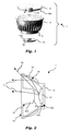
- reference 1 denotes as whole a compact LED module including (a single or multiple) LED lighting source 10 and comprised of just three basic components, namely:
- the PCB 12 is a metal-core PCB carrying, in addition to the LED lighting source 10, an electronic driver with associated power supply wires as well as the light source wire bonding connected with the driver.
- those elements are confined to the central portion of the side of the PCB 12 intended to face the reflector 14, thus forming an outer annular "free" area 120 adapted to face and abut against a corresponding inner annular "free” area 140 (see figure 2 ) at the end of the reflector 14 facing the PCB 12.
- the reflector 14 is a cup-shaped, approximately frusto-conical, hollow body of a heat conductive material (e.g. metal or plastics charges with heat conductive particles) having
- the PCB 12 and the proximal end of the reflector 14 jointly define a self-screwing, snap-in or analogous arrangement (e.g. mechanical interference coupling) to permit mechanical fixing and thermal coupling of the PCB 12 to the reflector 14.
- a self-screwing, snap-in or analogous arrangement e.g. mechanical interference coupling
- Any type of a quick release coupling can be used for that purpose, so that even an unskilled person can easily assemble, de-assemble and re-assemble the coupling of the PCB 12 with the reflector 14.
- the PCB 12 carries a similar fixing arrangement to permit an additional heat sink (not explicitly shown in the drawing) to be mechanically fixed and thermally coupled to the PCB 12.
- the heat sink/reflector 14 provides for dissipation of the heat coming from the LED source 10 and the electronic drive circuitry associated therewith. This occurs primarily via the external surface of the reflector 14 which is provided with fins 16 and/or similar heat dissipating formations.
- the reflector 14 is at least slightly dome-shaped and the fins 16 are in the form of arch-shaped ribs extending in a longitudinal direction to the reflector 14.
- the waved surface defined by the fins 16 is beneficial to improve dissipation.
- Various embodiments may comprise different configurations of waved external surface in addition to or as an alternative to the ribs or fins as shown in the figures.
- the cover 18 includes a disk-shaped body of a transparent material (e.g. plastics or other material fulfilling the desired functions) capable of integrating optical functions like collimating, broadening or mixing optical rays passing through.
- the cover 18 has the purpose of providing mechanical protection of the light source 10 against dust, undesired contact and also electrical protection both for the light source and the electronic driver circuit associated therewith.
- the cover 18 includes formations such as snap-in tongue-like formations 18a adapted to extend towards and into the reflector 14 to permit, e.g. a snap-in "plugging" the cover 18 into the mouth portion of the reflector 16.
- a single metal-core PCB 12 is used to mount both the LED source 10 and the associated drive circuitry.
- a metal-core PCB with good thermal dissipation provides a better behaviour in comparison to other arrangements adapted for mounting a LED source.
- a heat conductive material such as a thermal paste or a thin graphite layer interposed therebetween provides further improved thermal coupling.
- the mutually abutting surfaces 120, 140 are radially external and radially internal surfaces of the printed circuit board 12 and the reflector 14, respectively.
- Connection between the various elements aims at ensuring both thermal coupling and also reliable mechanical connection.
- Thermal coupling achieves good thermal behaviour of the whole system, while ensuring that this thermal behaviour is not adversely affected even if e.g. the LED source 10 is replaced by an unskilled user.
- Coupling of the reflector 14 and the cover 18 (which usually do not need to be disassembled when the light source 10 is replaced) is arranged in such a way to be particularly robust and stable.
- An additional feature for the LED module could be the possibility of substituting also the cover 18 in case of short lifetime (use of cheap short-lasting plastic material) or for providing differentiated optical performance (e.g. interchangeable covers with different view angles).
- connection between the PCB 12 and the reflector 14 also ensures that these elements can be easily disassembled and re-assembled to permit the replacement of the LED source 10.
- This approach takes into account a notional partition of the elements comprising the module 1 in view of their different lifetimes and the different rates of evolution of their related technology and standards.
- connection interface between the PCB 12 and the reflector 14 may adopt any known quick-release coupling (self-screwing and snap-in formations being exemplary of such couplings) thus making it easy, even for an unskilled person, to remove from the module a PCB 12 carrying a LED source 10 which has completed its useful life-cycle and replace it with a PCB 12 carrying a "new" LED source 10.
- the arrangement described herein thus decreases the average cost borne by the customer due the possibility of avoiding the unnecessary replacement of the long lasting components (heat sink/reflector 14 and cover 18).
- the environmental impact of the LED module is similarly reduced since the long-lasting sub-system can be used for long (notionally indefinitely).
- the arrangement described herein permits possibly to "upgrade" the LED module 1 by using light sources 10 in line with the technological evolution.
- the general dome shape of the reflector 14 mirrors the substantially parabolic inner surface of the reflector that provides optical collimation of the light coming from the source 10.
- the internal surface of the reflector is treated (e.g. metallised) in order to be reflective.
- the optical design of the reflector 14 (specifically of the internal surface thereof) aims at ensuring that the light rays from the LED source 10 are properly reflected from the LED source 10 towards the cover 18.
- the ray directions after reflection are set according to the specific viewing angle of the application and in order to hit the cover 18 in the outer part. This minimizes undesired overlapping of those rays coming from the reflector with those rays coming directly from the LED source 10.
- Use of facets at the inner surface of the reflector 14 provides improved colour and image mixing.
- the cover 18 integrates optical functions not performed by the reflector 14.
- the cover 18 thus co-operates with the reflector 14 by redirecting the rays coming directly from the LED source 10 (direct rays) while adjusting the direction of the rays coming from the reflector 14 (indirect rays).
- Such double function is performed at best when the overlapping area of direct and indirect rays is minimized thus increasing the degree of freedom in the optical design of the cover 18.
- the cover 18 projects and mixes the light rays in order to achieve the required intensity and colour uniformity of the spot.
- pillow or waved structures may be used.
- the cover 18 includes a central integrator 20 comprised of a (solid or hollow) hub of a transparent material performing optical collimation and spot shaping functions.
- the hub 20 can form an integrally moulded part of the cover 18.
- FIG. 2 refers to an embodiment where the central hub portion 20 protrudes towards the LED source 10 mounted on the PCB 12.
- the hub portion 20 includes a cylindrical or slightly tapered (e.g. frusto-conical) base portion 20a and a distal portion 20b having a convex end surface exposed to the LED source 10.
- a cylindrical or slightly tapered (e.g. frusto-conical) base portion 20a and a distal portion 20b having a convex end surface exposed to the LED source 10.
- the optical characteristics are selected in such a way that a part of the radiation from the LED source 10 and impinging on to the surface of the convex portion 20b of the hub 20 is refracted into the hub 20 and thus collimated toward the requested viewing angle.
- This is essentially the central part of the beam generated by the LED source 10 (i.e. the direct rays, designated IL in figure 2 ).
- the external portion of the rays impinging on to the surface 20b is reflected from that surface on to the surface of the reflector 14 to adjust the direction of rays coming from the reflector 14 (i.e. the indirect rays, designated OL in figure 2 ).
Priority Applications (1)
| Application Number | Priority Date | Filing Date | Title |
|---|---|---|---|
| EP08166838A EP2180233A1 (fr) | 2008-10-16 | 2008-10-16 | Module d'éclairage compact |
Applications Claiming Priority (1)
| Application Number | Priority Date | Filing Date | Title |
|---|---|---|---|
| EP08166838A EP2180233A1 (fr) | 2008-10-16 | 2008-10-16 | Module d'éclairage compact |
Publications (1)
| Publication Number | Publication Date |
|---|---|
| EP2180233A1 true EP2180233A1 (fr) | 2010-04-28 |
Family
ID=40456920
Family Applications (1)
| Application Number | Title | Priority Date | Filing Date |
|---|---|---|---|
| EP08166838A Withdrawn EP2180233A1 (fr) | 2008-10-16 | 2008-10-16 | Module d'éclairage compact |
Country Status (1)
| Country | Link |
|---|---|
| EP (1) | EP2180233A1 (fr) |
Cited By (11)
| Publication number | Priority date | Publication date | Assignee | Title |
|---|---|---|---|---|
| ITMI20100909A1 (it) * | 2010-05-20 | 2011-11-21 | Aldabra S R L | Lampada per interni o esterni |
| WO2012113532A1 (fr) * | 2011-02-23 | 2012-08-30 | Bartenbach Holding Gmbh | Dispositif d'éclairage |
| WO2012114241A3 (fr) * | 2011-02-24 | 2012-11-22 | Koninklijke Philips Electronics N.V. | Ensemble lampe |
| WO2013132446A1 (fr) * | 2012-03-08 | 2013-09-12 | Koninklijke Philips N.V. | Dispositif électroluminescent et procédé de fabrication correspondant |
| WO2014098931A1 (fr) * | 2012-12-21 | 2014-06-26 | Cree, Inc. | Lampe à diodes électroluminescentes (del) |
| GB2517064A (en) * | 2013-06-14 | 2015-02-11 | Aurora Ltd | Improved lighting unit |
| US9052093B2 (en) | 2013-03-14 | 2015-06-09 | Cree, Inc. | LED lamp and heat sink |
| US9097416B2 (en) | 2011-01-20 | 2015-08-04 | Koninklijke Philips N.V. | Multi-functional heat sink for lighting products |
| US9234638B2 (en) | 2012-04-13 | 2016-01-12 | Cree, Inc. | LED lamp with thermally conductive enclosure |
| USD748296S1 (en) | 2013-03-14 | 2016-01-26 | Cree, Inc. | LED lamp |
| US9951909B2 (en) | 2012-04-13 | 2018-04-24 | Cree, Inc. | LED lamp |
Citations (9)
| Publication number | Priority date | Publication date | Assignee | Title |
|---|---|---|---|---|
| AU2005100101A4 (en) * | 2005-02-03 | 2005-03-03 | Ian James Maitland | A lighting unit |
| US20060043546A1 (en) * | 2004-08-31 | 2006-03-02 | Robert Kraus | Optoelectronic component and housing |
| US20060261359A1 (en) * | 2005-05-18 | 2006-11-23 | Hsien-Jung Huang | Heat sink for light emitting diode bulb |
| US20060268555A1 (en) * | 2004-02-17 | 2006-11-30 | Kelly William M | Utility lamp |
| US20070091597A1 (en) * | 2005-01-06 | 2007-04-26 | Wang Hsu C | High power LED color bulb with infrared remote function |
| DE202007003679U1 (de) * | 2007-03-09 | 2007-05-16 | Hong Kuan Technology Co., Ltd., Sinjhuang City | Leuchtdiodenlampe |
| US20070195532A1 (en) * | 2006-02-21 | 2007-08-23 | Cml Innovative Technologies, Inc. | LED lamp module |
| US7349163B2 (en) * | 2001-12-06 | 2008-03-25 | Fraen Corporation S.R.L. | High-heat-dissipation lighting module |
| WO2008049381A1 (fr) * | 2006-10-25 | 2008-05-02 | Osram Gesellschaft mit beschränkter Haftung | Dispositif d'éclairage |
-
2008
- 2008-10-16 EP EP08166838A patent/EP2180233A1/fr not_active Withdrawn
Patent Citations (9)
| Publication number | Priority date | Publication date | Assignee | Title |
|---|---|---|---|---|
| US7349163B2 (en) * | 2001-12-06 | 2008-03-25 | Fraen Corporation S.R.L. | High-heat-dissipation lighting module |
| US20060268555A1 (en) * | 2004-02-17 | 2006-11-30 | Kelly William M | Utility lamp |
| US20060043546A1 (en) * | 2004-08-31 | 2006-03-02 | Robert Kraus | Optoelectronic component and housing |
| US20070091597A1 (en) * | 2005-01-06 | 2007-04-26 | Wang Hsu C | High power LED color bulb with infrared remote function |
| AU2005100101A4 (en) * | 2005-02-03 | 2005-03-03 | Ian James Maitland | A lighting unit |
| US20060261359A1 (en) * | 2005-05-18 | 2006-11-23 | Hsien-Jung Huang | Heat sink for light emitting diode bulb |
| US20070195532A1 (en) * | 2006-02-21 | 2007-08-23 | Cml Innovative Technologies, Inc. | LED lamp module |
| WO2008049381A1 (fr) * | 2006-10-25 | 2008-05-02 | Osram Gesellschaft mit beschränkter Haftung | Dispositif d'éclairage |
| DE202007003679U1 (de) * | 2007-03-09 | 2007-05-16 | Hong Kuan Technology Co., Ltd., Sinjhuang City | Leuchtdiodenlampe |
Cited By (15)
| Publication number | Priority date | Publication date | Assignee | Title |
|---|---|---|---|---|
| ITMI20100909A1 (it) * | 2010-05-20 | 2011-11-21 | Aldabra S R L | Lampada per interni o esterni |
| US9097416B2 (en) | 2011-01-20 | 2015-08-04 | Koninklijke Philips N.V. | Multi-functional heat sink for lighting products |
| EA026247B1 (ru) * | 2011-02-23 | 2017-03-31 | Бартенбах Холдинг Гмбх | Осветительное устройство |
| WO2012113532A1 (fr) * | 2011-02-23 | 2012-08-30 | Bartenbach Holding Gmbh | Dispositif d'éclairage |
| WO2012114241A3 (fr) * | 2011-02-24 | 2012-11-22 | Koninklijke Philips Electronics N.V. | Ensemble lampe |
| WO2013132446A1 (fr) * | 2012-03-08 | 2013-09-12 | Koninklijke Philips N.V. | Dispositif électroluminescent et procédé de fabrication correspondant |
| US10222048B2 (en) | 2012-03-08 | 2019-03-05 | Philips Lighting Holding B.V. | Light emitting device and method for manufacturing a light emitting device |
| US9234638B2 (en) | 2012-04-13 | 2016-01-12 | Cree, Inc. | LED lamp with thermally conductive enclosure |
| US9951909B2 (en) | 2012-04-13 | 2018-04-24 | Cree, Inc. | LED lamp |
| WO2014098931A1 (fr) * | 2012-12-21 | 2014-06-26 | Cree, Inc. | Lampe à diodes électroluminescentes (del) |
| US9052093B2 (en) | 2013-03-14 | 2015-06-09 | Cree, Inc. | LED lamp and heat sink |
| US9651239B2 (en) | 2013-03-14 | 2017-05-16 | Cree, Inc. | LED lamp and heat sink |
| USD748296S1 (en) | 2013-03-14 | 2016-01-26 | Cree, Inc. | LED lamp |
| GB2517064A (en) * | 2013-06-14 | 2015-02-11 | Aurora Ltd | Improved lighting unit |
| GB2517064B (en) * | 2013-06-14 | 2020-04-15 | Aurora Ltd | Improved lighting unit |
Similar Documents
| Publication | Publication Date | Title |
|---|---|---|
| EP2180233A1 (fr) | Module d'éclairage compact | |
| EP2458266B1 (fr) | Lampe à diodes électroluminescentes (DEL) | |
| TWI579491B (zh) | 發光二極體燈具 | |
| US7401945B2 (en) | Light source arrangement | |
| JP5779329B2 (ja) | 車両用灯具 | |
| US8330342B2 (en) | Spherical light output LED lens and heat sink stem system | |
| US7819538B2 (en) | Rotating lamp | |
| US9285082B2 (en) | LED lamp with LED board heat sink | |
| JP3998027B2 (ja) | Ledを用いた照明器具 | |
| US20110051448A1 (en) | Vehicle headlight | |
| CN1591924A (zh) | 表面安装型led及使用它的发光装置 | |
| JP2004179048A (ja) | Led照明ユニット及びled照明器具 | |
| US10082269B2 (en) | LED lamp | |
| US20130155674A1 (en) | Light-emitting device lamp | |
| JP2014026769A (ja) | 車両用前照灯 | |
| JP6239415B2 (ja) | 照明装置 | |
| US9182085B2 (en) | LED lighting device with upper heat dissipating structure | |
| JP2007311760A (ja) | Ledモジュール | |
| KR101071665B1 (ko) | 조명장치 | |
| US9890940B2 (en) | LED board with peripheral thermal contact | |
| JP6014311B2 (ja) | ランプ | |
| CN108388022A (zh) | 结构光投射器、深度相机和电子装置 | |
| KR20140053520A (ko) | 조명장치 | |
| US20080246045A1 (en) | Light-emitting diode packaging structure | |
| WO2023247513A1 (fr) | Module d'éclairage, lampe de véhicule et véhicule à moteur |
Legal Events
| Date | Code | Title | Description |
|---|---|---|---|
| PUAI | Public reference made under article 153(3) epc to a published international application that has entered the european phase |
Free format text: ORIGINAL CODE: 0009012 |
|
| AK | Designated contracting states |
Kind code of ref document: A1 Designated state(s): AT BE BG CH CY CZ DE DK EE ES FI FR GB GR HR HU IE IS IT LI LT LU LV MC MT NL NO PL PT RO SE SI SK TR |
|
| AX | Request for extension of the european patent |
Extension state: AL BA MK RS |
|
| AKY | No designation fees paid | ||
| REG | Reference to a national code |
Ref country code: DE Ref legal event code: 8566 |
|
| STAA | Information on the status of an ep patent application or granted ep patent |
Free format text: STATUS: THE APPLICATION IS DEEMED TO BE WITHDRAWN |
|
| 18D | Application deemed to be withdrawn |
Effective date: 20101029 |