EP2180181A1 - Structure de rotor d'une éolienne - Google Patents
Structure de rotor d'une éolienne Download PDFInfo
- Publication number
- EP2180181A1 EP2180181A1 EP08018610A EP08018610A EP2180181A1 EP 2180181 A1 EP2180181 A1 EP 2180181A1 EP 08018610 A EP08018610 A EP 08018610A EP 08018610 A EP08018610 A EP 08018610A EP 2180181 A1 EP2180181 A1 EP 2180181A1
- Authority
- EP
- European Patent Office
- Prior art keywords
- circumferential edge
- edge portion
- blades
- rotor
- hood
- Prior art date
- Legal status (The legal status is an assumption and is not a legal conclusion. Google has not performed a legal analysis and makes no representation as to the accuracy of the status listed.)
- Withdrawn
Links
Images


Classifications
-
- F—MECHANICAL ENGINEERING; LIGHTING; HEATING; WEAPONS; BLASTING
- F03—MACHINES OR ENGINES FOR LIQUIDS; WIND, SPRING, OR WEIGHT MOTORS; PRODUCING MECHANICAL POWER OR A REACTIVE PROPULSIVE THRUST, NOT OTHERWISE PROVIDED FOR
- F03D—WIND MOTORS
- F03D1/00—Wind motors with rotation axis substantially parallel to the air flow entering the rotor
- F03D1/04—Wind motors with rotation axis substantially parallel to the air flow entering the rotor having stationary wind-guiding means, e.g. with shrouds or channels
-
- F—MECHANICAL ENGINEERING; LIGHTING; HEATING; WEAPONS; BLASTING
- F05—INDEXING SCHEMES RELATING TO ENGINES OR PUMPS IN VARIOUS SUBCLASSES OF CLASSES F01-F04
- F05B—INDEXING SCHEME RELATING TO WIND, SPRING, WEIGHT, INERTIA OR LIKE MOTORS, TO MACHINES OR ENGINES FOR LIQUIDS COVERED BY SUBCLASSES F03B, F03D AND F03G
- F05B2240/00—Components
- F05B2240/20—Rotors
- F05B2240/33—Shrouds which are part of or which are rotating with the rotor
-
- Y—GENERAL TAGGING OF NEW TECHNOLOGICAL DEVELOPMENTS; GENERAL TAGGING OF CROSS-SECTIONAL TECHNOLOGIES SPANNING OVER SEVERAL SECTIONS OF THE IPC; TECHNICAL SUBJECTS COVERED BY FORMER USPC CROSS-REFERENCE ART COLLECTIONS [XRACs] AND DIGESTS
- Y02—TECHNOLOGIES OR APPLICATIONS FOR MITIGATION OR ADAPTATION AGAINST CLIMATE CHANGE
- Y02E—REDUCTION OF GREENHOUSE GAS [GHG] EMISSIONS, RELATED TO ENERGY GENERATION, TRANSMISSION OR DISTRIBUTION
- Y02E10/00—Energy generation through renewable energy sources
- Y02E10/70—Wind energy
- Y02E10/72—Wind turbines with rotation axis in wind direction
Definitions
- the wind energy is a non-exhaustible, non-polluting, and self-generated energy and has a wide distribution over the whole world so that it can be various local needs of power supply, reduces power loss due to long distance transmission, and lowers down the costs of power supplying.
- Wind power generation uses wind energy to drive the rotation of a rotor for conversion the wind energy into electrical power.
- aerodynamic performance (such as shape and number of blades) is critical to the output efficiency of the wind power generation.
- inventions related to the wind power generation such as US Patent No. 7, 094,018 B2 , Taiwan Utility Model Publication No. M279736, Design No. D 119380, and US Patent No. 4,075,500 .
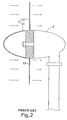
- a conventional rotor 1 comprises a central hub 11 from which a plurality of blades 12 radially extends.
- the rotor illustrated in the drawing is of a type having nine blades 12.
- the central hub 11 is coupled to a drive shaft of a generator 2.
- FIG. 2 when this type of known rotor 1 is put in operation, air flows caused by winds to move through the rotor 1 are broken by ends of the blades 12, leading to generation of noise and turbulences. The turbulences may cause expansion of the air flows, decelerating the air flow and thus reducing the rotational speed of the rotor 1 and eventually affecting the performance of wind power generation.
- an objective of the present invention is to provide a rotor structure of a wind turbine, which increases the speed of the air flow passing the rotor so as to improve performance of power generation.
- Another objective of the present invention is to provide a rotor structure of a wind turbine that reduces noise.
- a further obj ective of the present invention is to provide a rotor structure of a wind turbine that offers greater flexibility of design.
- a rotor structure of a wind turbine in accordance with the present invention comprises a central hub and a plurality of blades radially extending from the central hub.
- a hood is circumferentially set around and connected to distal free ends of the blades so that each blade is coupled to the hood to rotate therewith.
- the central hub of the rotor may be provided with a concentrically arranged connection ring to offer flexible increase of the number of blades between the central hub and the hood so as to increase the rotational torque of the rotor and also provide the effect of accelerating the rotation of the rotor.
- Comparison between the rotor of the present invention and the conventional rotor that is done by coupling theses rotors to generators that are of identical performance of power generation reveals that the size and the area of wind facing surface of the rotor of the present invention are far less than those of the conventional rotors.
- the present invention also offers the advantage of reducing the size of rotor.
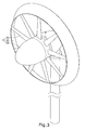
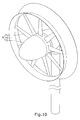
- a rotor constructed in accordance with the present invention generally designated with reference numeral 3 comprises a central hub 31 from which a plurality of blades 32 radially extends.
- the blades 32 have distal free ends that are surrounded by and coupled to a circumferentially arranged horn-like hood 33.
- the hood 33 has a first circumferential edge portion 331 and a second circumferential edge portion 332 and an extension section 333 formed and extending between the first circumferential edge portion 331 and the second circumferential edge portion 332.
- the first circumferential edge portion 331 has a diameter that is smaller than a diameter of the second circumferential edge portion 332 so that the extension section 333 of the hood 33 exhibits a divergent configuration.
- each blade 32 is connected to an inner surface of the first circumferential edge portion 331 and each blade 32 has a wind facing surface that is in a direction opposite to the extension section 333 of the hood 33.
- the extension section 333 of the hood 33 can be of an outward-deflected curved configuration (as shown in FIGS. 3 and 4 ) or a straight configuration that inclines outward (as shown in FIG. 5 ).
- a circular opening 51 is formed in a bottom of a container 5 that is full of liquid.
- the circular opening 51 has a cross-sectional area of A 1 and the speed of the liquid flow in the circular opening 51 is V 1 .
- the hood 52 in accordance with the present invention is designed on the basis of the effect of expansion to accelerate the speed of air flow and thus improve the performance of power generation. For example, increasing the flow speed to 1.1 times make an increase of power generated by 1.1 3 times, namely .133 times of power generated.
- the power generation performance is conventionally increased by increasing area, which makes the original size increased to 1.33 times to provide the same power generation performance.
- additional limitation is imposed to the installation thereof, making it difficult to get popular.
- the present invention allows a reduction of the cross-sectional area (in other words, reducing the overall size). Further, when the hood 33 is put in rotation, since no breaking of air flow occurs, the noise induced by the operation thereof can be reduced.
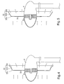
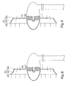
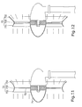
- the distal ends of the blades 62 that are mounted to the central hub 61 of the rotor 6 are similarly surrounded by and coupled to a horn-like hood 63 and the hood 63 has a first circumferential edge portion 631 and a second circumferential edge portion 632 with an extension section 633 similarly formed and extending between the first circumferential edge portion 631 and the second circumferential edge portion 632.
- the first circumferential edge portion 631 has a diameter that is greater than that of the second circumferential edge portion 632 so that the extension section 633 exhibits a convergent configuration.
- each blade 62 is connected to an inner surface of the second circumferential edge portion 632 and each blade 62 has a wind facing surface that is in the same direction as the extension section of the hood 63.
- the extension section 633 of the hood 63 is of an outward-deflected curved configuration (as shown in FIGS. 7 and 8 ) or a straight configuration that inclines outward (as shown in FIG. 9 ).
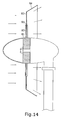
- the distal ends of the blades 72 that are mounted to the central hub 71 of the rotor 7 are provided with a horn-like hood 73.
- Two opposite side portions of the hood 73 respectively comprises a first circumferential edge portion 731 and a second circumferential edge portion 732, both being convergent, with an extension section 733 similarly formed and extending therebetween.
- Each blade 72 is connected to the inner surface of the extension section 733 and each blade 72 has a wind facing surface that is in a direction toward the first circumferential edge portion 731.
- the portion of the hood 73 from the first circumferential edge portion 731 to the extension section 733 is of an inward-deflected curved configuration (see FIG.
- the first circumferential edge portion 731 has a diameter that is smaller than that of the second circumferential edge portion 732.
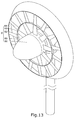
- the present inventor makes a further improvement to the construction of the blades 82 of the rotor 8, wherein the central hub 81 of the rotor 8 is provided, at an outer side thereof, with at least one concentrically arranged connection ring 83 and a plurality of blades 82 connects between the connection ring 83 and the central hub 81, while another plurality of blades 82 connects between the connection ring 83 and the hood 84.
- the number of the blades 82 that connect between the connection ring 83 and the central hub 81 is less than that of the blades 82 connecting between the connection ring 83 and the hood 84.
- the blades 82 between the connection ring 83 and the hood 84 are used to increase the rotational torque of rotor 8 without affecting incoming air flow rate (or also referred to as thickness) so as to increase the rotational speed of the rotor 8 and improve power generation performance.
- the configuration of the hood 84 can be any one of the hoods 33, 63, 73 illustrated in FIGS. 3-12 , such as the divergent hood 33, the convenient hood 63 or the convergent-divergent hood 73, and the hood 84 is connected to the outer set of the blades 82 to also effect increase of air flow speed and improvement of power generation performance.
- the present inventor has taken records of the operations of the conventional rotor, the divergent rotor, and the multi-stage-blade rotor and comparison is made for the torque-rotational speed relationship and the performance-rotational speed relationship to evidence the difference between the present invention and the conventional techniques and the improved performance realized by the present invention.
- L 1 indicates the torque-rotational speed curve of the conventional rotor
- L 2 is the torque-rotational speed curve of the divergent rotor
- L 3 is the torque-rotational speed curve of the multi-stage-blade rotor, for there is a corresponding relationship between the torque and the angular momentum that drives the rotation of the rotor.
- the rotational speed is zero (0)
- the torque generated is referred to as the brake torque (the higher the better).
- the brake torque the higher the better.
- Comparison of theses curves indicates that the curve having a peak showing up earliest is Curve L 3 (the earlier the better), and then sequentially Curve L 2 and Curve L 1 . It can be seen that the peak torque value of the present invention appears in a lower rotational speed and thus, a good angular momentum can be obtained early at a low rotational speed, resulting in excellent power generation performance.
- L 4 indicates a performance-rotational speed curve of the conventional rotor
- L 5 is the performance-rotational speed curve of the divergent rotor
- L 6 is the performance-rotational speed curve of the multi-stage-blade rotor.
- the performance curve of each rotor can be calculated.
- the maximum performance of the conventional rotor for conversion of wind power into mechanical power is 0.593, which is set by Betz limit and the performance can be calculated by multiplying it with a power coefficient.
- the performance provided by the present invention is higher than that of the conventional techniques. In other words, using the present invention to generate power has a higher performance.
Priority Applications (1)
| Application Number | Priority Date | Filing Date | Title |
|---|---|---|---|
| EP08018610A EP2180181A1 (fr) | 2008-10-23 | 2008-10-23 | Structure de rotor d'une éolienne |
Applications Claiming Priority (1)
| Application Number | Priority Date | Filing Date | Title |
|---|---|---|---|
| EP08018610A EP2180181A1 (fr) | 2008-10-23 | 2008-10-23 | Structure de rotor d'une éolienne |
Publications (1)
| Publication Number | Publication Date |
|---|---|
| EP2180181A1 true EP2180181A1 (fr) | 2010-04-28 |
Family
ID=40743896
Family Applications (1)
| Application Number | Title | Priority Date | Filing Date |
|---|---|---|---|
| EP08018610A Withdrawn EP2180181A1 (fr) | 2008-10-23 | 2008-10-23 | Structure de rotor d'une éolienne |
Country Status (1)
| Country | Link |
|---|---|
| EP (1) | EP2180181A1 (fr) |
Citations (9)
| Publication number | Priority date | Publication date | Assignee | Title |
|---|---|---|---|---|
| US4075500A (en) | 1975-08-13 | 1978-02-21 | Grumman Aerospace Corporation | Variable stator, diffuser augmented wind turbine electrical generation system |
| WO2004083631A2 (fr) * | 2003-03-18 | 2004-09-30 | Renewable Devices Swift Turbines Limited | Eolienne |
| TWM279736U (en) | 2005-07-14 | 2005-11-01 | Jetpo Technology Inc | Improved mechanism of a wind power generator |
| WO2006007696A1 (fr) * | 2004-07-16 | 2006-01-26 | Tocher Angus J | Systeme d'extraction d'energie eolienne |
| US7094018B2 (en) | 2004-05-07 | 2006-08-22 | Grubb Kelly W | Wind power generator |
| WO2006137780A1 (fr) * | 2005-06-22 | 2006-12-28 | Knes Of Sweden Ab | Dispositif de transformation d'energie |
| WO2007043894A1 (fr) * | 2005-10-13 | 2007-04-19 | Sway As | Générateur/moteur à entraînement direct pour centrale éolienne/hydraulique/cuve, le moteur générateur étant conçu comme profilé creux et procédé d’assemblage de ladite centrale éolienne/ hydraulique |
| US20080232957A1 (en) * | 2007-03-23 | 2008-09-25 | Presz Walter M | Wind turbine with mixers and ejectors |
| WO2008120026A2 (fr) * | 2007-03-30 | 2008-10-09 | Bosa Sa | Eolienne à axe horizontal innovante présentant un rendement élevé |
-
2008
- 2008-10-23 EP EP08018610A patent/EP2180181A1/fr not_active Withdrawn
Patent Citations (9)
| Publication number | Priority date | Publication date | Assignee | Title |
|---|---|---|---|---|
| US4075500A (en) | 1975-08-13 | 1978-02-21 | Grumman Aerospace Corporation | Variable stator, diffuser augmented wind turbine electrical generation system |
| WO2004083631A2 (fr) * | 2003-03-18 | 2004-09-30 | Renewable Devices Swift Turbines Limited | Eolienne |
| US7094018B2 (en) | 2004-05-07 | 2006-08-22 | Grubb Kelly W | Wind power generator |
| WO2006007696A1 (fr) * | 2004-07-16 | 2006-01-26 | Tocher Angus J | Systeme d'extraction d'energie eolienne |
| WO2006137780A1 (fr) * | 2005-06-22 | 2006-12-28 | Knes Of Sweden Ab | Dispositif de transformation d'energie |
| TWM279736U (en) | 2005-07-14 | 2005-11-01 | Jetpo Technology Inc | Improved mechanism of a wind power generator |
| WO2007043894A1 (fr) * | 2005-10-13 | 2007-04-19 | Sway As | Générateur/moteur à entraînement direct pour centrale éolienne/hydraulique/cuve, le moteur générateur étant conçu comme profilé creux et procédé d’assemblage de ladite centrale éolienne/ hydraulique |
| US20080232957A1 (en) * | 2007-03-23 | 2008-09-25 | Presz Walter M | Wind turbine with mixers and ejectors |
| WO2008120026A2 (fr) * | 2007-03-30 | 2008-10-09 | Bosa Sa | Eolienne à axe horizontal innovante présentant un rendement élevé |
Similar Documents
| Publication | Publication Date | Title |
|---|---|---|
| US6127739A (en) | Jet assisted counter rotating wind turbine | |
| US9284944B2 (en) | Vertical shaft type darius windmill | |
| US7600963B2 (en) | Fluid energy converter | |
| US20080075599A1 (en) | Fluid energy converter | |
| US4781522A (en) | Turbomill apparatus and method | |
| US9194371B2 (en) | Wind turbine | |
| CN201090372Y (zh) | 多级风力发电机 | |
| US20110305570A1 (en) | Aerodynamic dead zone-less triple rotors integrated wind power driven system | |
| US20100301612A1 (en) | Wind turbine | |
| TWI709689B (zh) | 交通載具的風力發電設備 | |
| EP3613980A1 (fr) | Turbine à axe vertical | |
| EP2258941A1 (fr) | Éolienne | |
| US20100098543A1 (en) | Rotor structure of wind turbine | |
| RU2392486C1 (ru) | Ротор ветряной турбины | |
| AU2010264534B2 (en) | Wind turbine | |
| EP2180181A1 (fr) | Structure de rotor d'une éolienne | |
| EP3396153A1 (fr) | Une combinaison d'une turbine à jet de vent et d'une éolienne | |
| CA2645133C (fr) | Structure rotorique d'eolienne | |
| CN201090373Y (zh) | 对转风力发电机 | |
| EP1764503A2 (fr) | Rotor d'une éolienne | |
| US20240055949A1 (en) | Wind turbine generator rotor arrangement | |
| CN111120211A (zh) | 一种风力涡轮机驱动机构及风力涡轮机 | |
| RU2293211C1 (ru) | Ротор ветродвигателя | |
| US20180017037A1 (en) | Hub and Rotor Assemby for Wind Turbines with Conjoined Turbine Blades | |
| CN101684770A (zh) | 风力发电机的叶轮构造 |
Legal Events
| Date | Code | Title | Description |
|---|---|---|---|
| PUAI | Public reference made under article 153(3) epc to a published international application that has entered the european phase |
Free format text: ORIGINAL CODE: 0009012 |
|
| 17P | Request for examination filed |
Effective date: 20081024 |
|
| AK | Designated contracting states |
Kind code of ref document: A1 Designated state(s): AT BE BG CH CY CZ DE DK EE ES FI FR GB GR HR HU IE IS IT LI LT LU LV MC MT NL NO PL PT RO SE SI SK TR |
|
| AX | Request for extension of the european patent |
Extension state: AL BA MK RS |
|
| AKX | Designation fees paid |
Designated state(s): AT BE BG CH CY CZ DE DK EE ES FI FR GB GR HR HU IE IS IT LI LT LU LV MC MT NL NO PL PT RO SE SI SK TR |
|
| 17Q | First examination report despatched |
Effective date: 20110125 |
|
| STAA | Information on the status of an ep patent application or granted ep patent |
Free format text: STATUS: THE APPLICATION IS DEEMED TO BE WITHDRAWN |
|
| 18D | Application deemed to be withdrawn |
Effective date: 20110607 |