EP2180096A2 - Box of intermediate plates having an elastic plate of adjustable elasticity - Google Patents
Box of intermediate plates having an elastic plate of adjustable elasticity Download PDFInfo
- Publication number
- EP2180096A2 EP2180096A2 EP09380171A EP09380171A EP2180096A2 EP 2180096 A2 EP2180096 A2 EP 2180096A2 EP 09380171 A EP09380171 A EP 09380171A EP 09380171 A EP09380171 A EP 09380171A EP 2180096 A2 EP2180096 A2 EP 2180096A2
- Authority
- EP
- European Patent Office
- Prior art keywords
- elastic plate
- box
- base
- plate
- cover
- Prior art date
- Legal status (The legal status is an assumption and is not a legal conclusion. Google has not performed a legal analysis and makes no representation as to the accuracy of the status listed.)
- Withdrawn
Links
Images




Classifications
-
- E—FIXED CONSTRUCTIONS
- E01—CONSTRUCTION OF ROADS, RAILWAYS, OR BRIDGES
- E01B—PERMANENT WAY; PERMANENT-WAY TOOLS; MACHINES FOR MAKING RAILWAYS OF ALL KINDS
- E01B9/00—Fastening rails on sleepers, or the like
- E01B9/68—Pads or the like, e.g. of wood, rubber, placed under the rail, tie-plate, or chair
- E01B9/681—Pads or the like, e.g. of wood, rubber, placed under the rail, tie-plate, or chair characterised by the material
- E01B9/683—Pads or the like, e.g. of wood, rubber, placed under the rail, tie-plate, or chair characterised by the material layered or composite
-
- E—FIXED CONSTRUCTIONS
- E01—CONSTRUCTION OF ROADS, RAILWAYS, OR BRIDGES
- E01B—PERMANENT WAY; PERMANENT-WAY TOOLS; MACHINES FOR MAKING RAILWAYS OF ALL KINDS
- E01B9/00—Fastening rails on sleepers, or the like
- E01B9/62—Rail fastenings incorporating resilient supports
Definitions
- the invention refers to, as expressed on the wording of this descriptive report, a box of intermediate plates with an elastic plate of adjustable elasticity, which provides to the function it is assigned to, a number of advantages and characteristics, apart from those inherent to its organization and constitution, to be detailed afterwards, which imply an innovative improvement in this field.
- the object of the invention consists of a compact structure of plates which constitute a box, assigned to be located under the base plate of any indirect rail fastening system, its aim being to give elasticity to such system.
- the structure mainly comprises an intermediate elastic plate located inside a box, which is composed of an intermediate cap plate, acting as a cover, and an intermediate protection plate, acting as a base.
- intermediate plate As opposed to the under rail plate located on the base plate of an indirect rail fastening system.
- This invention has its field of application in the industry dedicated to the manufacturing of equipment for railroad transportation systems, and especially to slab track systems.
- a slab track or track on a concrete slab is an infrastructure system whose aim is to improve rail quality and reduce excessive railroad maintenance costs. Its main characteristic is that it is manufactured without ballast. It consists of a concrete slab which transmits a uniform stress distribution to the platform, but of a lower value, and has the advantages of supporting higher loads per axle, decreasing pressure transmitted to the platform, and having remarkably lower maintenance costs.
- Parts of slab track are:
- the structure which constitutes the box supported by this invention as previously mentioned composed of an intermediate elastic plate located inside a box which comprises respectively an intermediate cap plate acting as a cover and an intermediate protection plate acting as a base, has two main properties: elasticity and compactness.
- the elasticity is given by the intermediate element of the structure, known as intermediate elastic plate, having adjustable elasticity.
- the compactness is obtained by protecting such intermediate elastic plate through a closed box, which is composed of a cover known as intermediate cap plate and a base known as intermediate protection plate, both of them made of a comparatively much more rigid material than the intermediate elastic plate.
- the intermediate cap plate or cover is located in the upper part of the box structure, in direct contact with the base plate of the indirect rail fastening system under which the structure is situated. Such cover is used to close the box and thus protect the intermediate elastic plate which is placed inside.
- the cover allows a vertical movement by means of a flange system, but not to move upward beyond a limit.
- the said flanges are part of the pre-assembly system, since they must be able to support the weight of the box structure. They will allow two possible pre-assemblies: of the box structure during its transportation and of the box structure with a base plate having a compatible assembly.
- a lug system is disposed on the upper face of the cover or intermediate cap plate, that is, on the face in contact with the base plate, for a possible assembly under such base plate.
- the cover is of a much more rigid material than the elastic plate and must distribute and transmit the loads from the rail through the base plate of the indirect rail fastening system.
- the intermediate protection plate or base constitutes the base of the box and is complementary to the previously described cover in the protection of the intermediate elastic plate.
- the base has, jointly with the cover, a slightly bigger perimeter than the one of the intermediate elastic plate, forming a breathing zone which allows the expansion of the intermediate elastic plate under compression load.
- Both the base and the cover have in common their rectangular shape and the corners, which are widely rounded.
- the base gives lateral and lower protection to the structure during the building of the slab on which it will lean on in the end, and during all its useful life.
- the base allows the intermediate elastic plate that is received to have a stable and homogeneous support. Besides, it has plural accommodations, just like the cover or cap plate, to position the elastic plate and prevent its movement during the handling and transportation of the structure.
- the intermediate elastic plate is settled inside the box, composed, as mentioned before, of an intermediate cap plate or cover and an intermediate protection plate or base.
- the elastic plate is adjustable to the cover and the base of the box, between which it is positioned by means of small lugs, disposed on the corners and coupled in the corresponding accommodations assigned for that purpose in the inner faces of the cover and the base. This is useful to prevent any kind of movement inside the structure, previously mounted, during its handling and transportation.
- the sides of the said intermediate elastic plate are provided with hollows to allow a better expansion under compression load.
- the box containing it has a breathing zone in its perimeter to prevent the sides of the elastic plate from bumping into the inner walls of the box in cases of extreme loads.
- the upper face of the elastic plate has wave shapes consisting of ridges and valleys, constituted by spherical caps.
- the perimeter zone can be smooth or nonexistent.
- the inner face is provided with lightening mounting holes.
- the elastic plate gives elasticity to the structure.
- the valleys can be emptied or filled; the perimeter zone can be smooth, with a variable thickness and height or nonexistent; and the lightening mounting holes of the inner face also allow to adjust elasticity by means of lightening combinations.
- the intrinsic properties of the elastomeric material of the intermediate elastic plate constitute the other factor to give elasticity.
- the box structure of intermediate plates having an elastic plate of adjustable elasticity supported by the invention can be adapted to any kind of base plate of an indirect rail fastening system. This implies the advantage of being adaptable to different combinations, locations and shapes of the through bores used for the insertion of fixing screws.
- the box of intermediate plates having an elastic plate of adjustable elasticity supported by this invention represents an innovative structure with structural and constitutive characteristics not known so far for such purpose, reasons which, together with its practical usefulness, grant enough basis to obtain the exclusiveness privilege applied for.
- the said box (1) aimed, as previously mentioned, at being placed under the base plate of any indirect rail fastening system so as to give elasticity, is basically constituted through a set of intermediate plates, which comprises an intermediate cap plate acting as a cover (2) of the box, an intermediate protection plate acting as a base (3) of the box, and an intermediate elastic plate (4) of adjustable elasticity located inside the box (1) between them.
- the cover (2) and the base (3) have a slightly bigger perimeter than the intermediate elastic plate (4), forming a breathing zone (9) aimed at allowing the expansion of the intermediate elastic plate (4) under compression load.
- both the cover (2) and the base (3) have a rectangular shape with widely rounded corners.
- the cover (2) or intermediate cap plate located in the upper part of the box structure (1), in direct contact with the base plate of the indirect rail fastening system to which it is applied, is used to close the box (1) and protect the intermediate elastic plate (4) which is placed inside.
- Such cover (2) which is made of a much more rigid material than the intermediate elastic plate (4) due to its supporting function, is provided with a flange system (5) in its perimeter, adapted to fit into some accommodations (6) disposed on the base (3), allowing their vertical movement, but not to move upward beyond a limit.
- the upper face of the cover (2) that is, the face in contact with the base plate of the fastening system, is provided with lugs (7) for its possible pre-assembly under the said base plate.
- some accommodations (8) are disposed on the inner face of the cover (2) to position the intermediate elastic plate (4) and prevent its movement during the handling and transportation of the box structure (1), the rest of the surfaces of the cover (2) being completely smooth to allow an appropriate deformation of the intermediate elastic plate (4).
- the base (3) or intermediate protection plate constitutes the base of the box (1) and complements the already described cover (2) in the protection of the intermediate elastic plate (4).
- the base (3) which gives lateral and lower protection to the structure, is provided with the aforementioned accommodations (6) along the inner perimeter of its lateral wall (10), aimed at receiving the flanges (5) of the cover (2).
- Such accommodations (6) are respective to the said flanges (5) and have slightly bigger dimensions.
- the base (3) is built with the same material as the cover (2), so that it may have a lower thickness which makes possible to optimise the total thickness of the box (1), and get the intermediate elastic plate (4) to have a maximum thickness.
- the intermediate elastic plate (4) made of an elastomeric material and placed inside the box (1), as can be seen in Figures 4-A to 4-E , is positioned between the cover (2) and the base (3) which constitute such box (1) by means of small lugs (12), disposed on the corners and fitted into the corresponding accommodations (8) and (11), assigned for that purpose in the inner faces of the cover (2) and the base (3).
- the sides of the intermediate elastic plate (4) are provided with hollows (13) whose purpose it to allow a better expansion of the plate under compression load, the previously mentioned breathing zone (9) being disposed to prevent the said sides of the intermediate elastic plate (4) from bumping into the inner walls of the box in cases of extreme loads.
- the upper face of the intermediate elastic plate (4) has wave shapes consisting of ridges (14) and valleys (15), constituted by spherical caps, the perimeter zone (16) can be smooth or nonexistent, and the inner face is provided with lightening cavities (17) in the shape of mounting holes aimed at allowing to adjust its elasticity.
- the box structure may be adapted to any kind of base plate of an indirect rail fastening system, for which the cover (2), the base (3) and the intermediate elastic plate (4) have through bores (18), suitable for the insertion of fixing screws, which may have different combinations, locations and shapes.
Landscapes
- Engineering & Computer Science (AREA)
- Mechanical Engineering (AREA)
- Architecture (AREA)
- Civil Engineering (AREA)
- Structural Engineering (AREA)
- Details Of Indoor Wiring (AREA)
- Buffer Packaging (AREA)
- Roof Covering Using Slabs Or Stiff Sheets (AREA)
Abstract
Description
- The invention refers to, as expressed on the wording of this descriptive report, a box of intermediate plates with an elastic plate of adjustable elasticity, which provides to the function it is assigned to, a number of advantages and characteristics, apart from those inherent to its organization and constitution, to be detailed afterwards, which imply an innovative improvement in this field.
- Specifically, the object of the invention consists of a compact structure of plates which constitute a box, assigned to be located under the base plate of any indirect rail fastening system, its aim being to give elasticity to such system. The structure mainly comprises an intermediate elastic plate located inside a box, which is composed of an intermediate cap plate, acting as a cover, and an intermediate protection plate, acting as a base.
- Each of the elements of the structure composing the box mentioned before, along with its properties, is known as "intermediate plate", as opposed to the under rail plate located on the base plate of an indirect rail fastening system.
- This invention has its field of application in the industry dedicated to the manufacturing of equipment for railroad transportation systems, and especially to slab track systems.
- As is widely known, a slab track or track on a concrete slab is an infrastructure system whose aim is to improve rail quality and reduce excessive railroad maintenance costs. Its main characteristic is that it is manufactured without ballast. It consists of a concrete slab which transmits a uniform stress distribution to the platform, but of a lower value, and has the advantages of supporting higher loads per axle, decreasing pressure transmitted to the platform, and having remarkably lower maintenance costs.
- Parts of slab track are:
- A concrete slab.
- An intermediate plate which gives elasticity to the track.
- A base plate, much more rigid, which supports and transmits the loads to the slab. It has a double fastening system: from the base plate to the slab anchorage, and from the rail to the base plate.
- An under rail plate, which can also give elasticity to the track and support directly the load of the rail.
- And a rail, anchored to the base plate by means of an elastic fastening system.
- Nowadays, and as a reference to the status of technique, it has to be mentioned that the applicant is not aware of the existence, for the purpose herein concerned, of any other invention with technical, structural and constitutive characteristics similar to the ones of the box of intermediate plates having an elastic plate of adjustable elasticity supported by this invention, whose main objective is to give elasticity to the indirect rail fastening systems.
- In this way, the device supported by the invention, as stated, represents an important novelty in its field of invention, its characterizing features being suitably compiled in the claims of this descriptive report.
- Specifically, the structure which constitutes the box supported by this invention, as previously mentioned composed of an intermediate elastic plate located inside a box which comprises respectively an intermediate cap plate acting as a cover and an intermediate protection plate acting as a base, has two main properties: elasticity and compactness.
- The elasticity is given by the intermediate element of the structure, known as intermediate elastic plate, having adjustable elasticity.
- The compactness is obtained by protecting such intermediate elastic plate through a closed box, which is composed of a cover known as intermediate cap plate and a base known as intermediate protection plate, both of them made of a comparatively much more rigid material than the intermediate elastic plate.
- All these things considered, we now proceed to specify the characteristics and functions of each of the said intermediate plates composing the box object of the invention.
- The intermediate cap plate or cover is located in the upper part of the box structure, in direct contact with the base plate of the indirect rail fastening system under which the structure is situated. Such cover is used to close the box and thus protect the intermediate elastic plate which is placed inside. The cover allows a vertical movement by means of a flange system, but not to move upward beyond a limit.
- The said flanges are part of the pre-assembly system, since they must be able to support the weight of the box structure. They will allow two possible pre-assemblies: of the box structure during its transportation and of the box structure with a base plate having a compatible assembly. For that purpose, a lug system is disposed on the upper face of the cover or intermediate cap plate, that is, on the face in contact with the base plate, for a possible assembly under such base plate.
- On the other hand, some accommodations are disposed on the inner face of the cover to position the elastic plate and prevent its movement during the handling and transportation of the box structure. The rest of the surfaces of the cover is completely smooth to allow an appropriate deformation of the intermediate elastic plate.
- The cover is of a much more rigid material than the elastic plate and must distribute and transmit the loads from the rail through the base plate of the indirect rail fastening system.
- In contrast with this, the intermediate protection plate or base constitutes the base of the box and is complementary to the previously described cover in the protection of the intermediate elastic plate. The base has, jointly with the cover, a slightly bigger perimeter than the one of the intermediate elastic plate, forming a breathing zone which allows the expansion of the intermediate elastic plate under compression load. Both the base and the cover have in common their rectangular shape and the corners, which are widely rounded.
- The base gives lateral and lower protection to the structure during the building of the slab on which it will lean on in the end, and during all its useful life.
- It is important to remark that plural accommodations are disposed along the inner perimeter of the lateral wall of the base, suitable to receive the aforementioned flanges of the cover, and aimed at allowing them to perform a vertical movement but not to exceed a limit, which is why they are positioned to be coincident with the flanges and also have slightly bigger dimensions.
- Innerly, the base allows the intermediate elastic plate that is received to have a stable and homogeneous support. Besides, it has plural accommodations, just like the cover or cap plate, to position the elastic plate and prevent its movement during the handling and transportation of the structure.
- It must be stated that although, contrary to the cover, a specific resistance is not necessary for the load distribution, the fact that the base is built with the same material as the cover will allow it to have a lower thickness, which will make possible to optimise the total thickness of the box, and thus get the intermediate elastic plate to have a maximum thickness. Consequently, its resistant function will be analogous to the one of the cover.
- Finally, the intermediate elastic plate is settled inside the box, composed, as mentioned before, of an intermediate cap plate or cover and an intermediate protection plate or base. The elastic plate is adjustable to the cover and the base of the box, between which it is positioned by means of small lugs, disposed on the corners and coupled in the corresponding accommodations assigned for that purpose in the inner faces of the cover and the base. This is useful to prevent any kind of movement inside the structure, previously mounted, during its handling and transportation.
- In a plan view, the sides of the said intermediate elastic plate are provided with hollows to allow a better expansion under compression load. As mentioned before, the box containing it has a breathing zone in its perimeter to prevent the sides of the elastic plate from bumping into the inner walls of the box in cases of extreme loads.
- It is also important to remark that the upper face of the elastic plate has wave shapes consisting of ridges and valleys, constituted by spherical caps. The perimeter zone can be smooth or nonexistent. In addition, the inner face is provided with lightening mounting holes.
- With regard to its functionality, as previously mentioned, the elastic plate gives elasticity to the structure. The ridges and the valleys, the smooth perimeter surface and the mounting holes, which are part of the plate geometry, make possible to adjust its elasticity.
- So, the valleys can be emptied or filled; the perimeter zone can be smooth, with a variable thickness and height or nonexistent; and the lightening mounting holes of the inner face also allow to adjust elasticity by means of lightening combinations.
- The intrinsic properties of the elastomeric material of the intermediate elastic plate constitute the other factor to give elasticity.
- Therefore, the box structure of intermediate plates having an elastic plate of adjustable elasticity supported by the invention can be adapted to any kind of base plate of an indirect rail fastening system. This implies the advantage of being adaptable to different combinations, locations and shapes of the through bores used for the insertion of fixing screws.
- Finally, it is important to remark that according to the final location of the indirect rail fastening system and the level of protection which is given to the intermediate elastic plate, it will be possible to seal the box with an elastic joint adapted system.
- Consequently, the box of intermediate plates having an elastic plate of adjustable elasticity supported by this invention represents an innovative structure with structural and constitutive characteristics not known so far for such purpose, reasons which, together with its practical usefulness, grant enough basis to obtain the exclusiveness privilege applied for.
- In order to complete this description and to ease a better understanding of the invention, we attach to this descriptive report, making part of the same, a set of layouts where, with an illustrative non limitative character, the following has been represented:
- Figures number 1-A to 1-E show plural views of the box of intermediate plates having an elastic plate of adjustable elasticity object of the invention, already mounted, where the main parts and elements, along with their configuration and disposition can be seen. Specifically,
Figure 1-A is a perspective view,Figure 1-B is a plan view,Figure 1-C is a cross-sectional view, andFigures 1-D and 1-D show some enlarged details of a section ofFigure 1-C . -
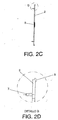
Figures 2-A, 2-B ,2-C and 2-D show, respectively, a down plan view, a top plan view, an elevation view and detail of the intermediate cap plate or cover of the box according to the invention, displaying its general configuration and its different constitutive parts and elements. -
Figures 3-A, 3-B ,3-C and 3-D show, respectively, a down plan view, a top plan view, a cross-sectional view and detail of the intermediate protection plate or base of the box. -
Figures 4-A, 4-B ,4-C, 4-D and 4-E show, respectively, a perspective view, a down plan view, a top plan view, a cross-sectional view and detail of the intermediate elastic plate. - In the light of the said figures, and according to their numbering, it may be seen different prefered embodiments of the device in question formed by the parts and elements described in detail hereinafter.
Therefore, as the Figures show, the said box (1) aimed, as previously mentioned, at being placed under the base plate of any indirect rail fastening system so as to give elasticity, is basically constituted through a set of intermediate plates, which comprises an intermediate cap plate acting as a cover (2) of the box, an intermediate protection plate acting as a base (3) of the box, and an intermediate elastic plate (4) of adjustable elasticity located inside the box (1) between them.
As can be seen inFigure 1-B , the cover (2) and the base (3) have a slightly bigger perimeter than the intermediate elastic plate (4), forming a breathing zone (9) aimed at allowing the expansion of the intermediate elastic plate (4) under compression load.
Likewise, it must be stated that both the cover (2) and the base (3) have a rectangular shape with widely rounded corners.
According toFigures 2-A to 2-D , the cover (2) or intermediate cap plate, located in the upper part of the box structure (1), in direct contact with the base plate of the indirect rail fastening system to which it is applied, is used to close the box (1) and protect the intermediate elastic plate (4) which is placed inside.
Such cover (2), which is made of a much more rigid material than the intermediate elastic plate (4) due to its supporting function, is provided with a flange system (5) in its perimeter, adapted to fit into some accommodations (6) disposed on the base (3), allowing their vertical movement, but not to move upward beyond a limit.
Besides, the upper face of the cover (2), that is, the face in contact with the base plate of the fastening system, is provided with lugs (7) for its possible pre-assembly under the said base plate.
In contrast with this, some accommodations (8) are disposed on the inner face of the cover (2) to position the intermediate elastic plate (4) and prevent its movement during the handling and transportation of the box structure (1), the rest of the surfaces of the cover (2) being completely smooth to allow an appropriate deformation of the intermediate elastic plate (4). - As can be observed in
Figures 3-A to 3-D , the base (3) or intermediate protection plate constitutes the base of the box (1) and complements the already described cover (2) in the protection of the intermediate elastic plate (4). - The base (3), which gives lateral and lower protection to the structure, is provided with the aforementioned accommodations (6) along the inner perimeter of its lateral wall (10), aimed at receiving the flanges (5) of the cover (2). Such accommodations (6) are respective to the said flanges (5) and have slightly bigger dimensions.
- Innerly, similar to the cover (2), it has plural accommodations (11) to position the elastic plate and prevent its movement during the handling and transportation of the structure.
- The base (3) is built with the same material as the cover (2), so that it may have a lower thickness which makes possible to optimise the total thickness of the box (1), and get the intermediate elastic plate (4) to have a maximum thickness.
- On the other side, the intermediate elastic plate (4), made of an elastomeric material and placed inside the box (1), as can be seen in
Figures 4-A to 4-E , is positioned between the cover (2) and the base (3) which constitute such box (1) by means of small lugs (12), disposed on the corners and fitted into the corresponding accommodations (8) and (11), assigned for that purpose in the inner faces of the cover (2) and the base (3). - It is also important to remark that the sides of the intermediate elastic plate (4) are provided with hollows (13) whose purpose it to allow a better expansion of the plate under compression load, the previously mentioned breathing zone (9) being disposed to prevent the said sides of the intermediate elastic plate (4) from bumping into the inner walls of the box in cases of extreme loads.
- Besides, the upper face of the intermediate elastic plate (4) has wave shapes consisting of ridges (14) and valleys (15), constituted by spherical caps, the perimeter zone (16) can be smooth or nonexistent, and the inner face is provided with lightening cavities (17) in the shape of mounting holes aimed at allowing to adjust its elasticity.
- As previously mentioned, the box structure may be adapted to any kind of base plate of an indirect rail fastening system, for which the cover (2), the base (3) and the intermediate elastic plate (4) have through bores (18), suitable for the insertion of fixing screws, which may have different combinations, locations and shapes.
- It will be possible to seal the box (1) with an elastic joint adapted system, according to the final location of the indirect rail fastening system and the level of protection which is given to the intermediate elastic plate (4).
- Being already described the nature of this invention, as well as the way to put it into practice, it is not considered necessary to make an extensive description for an expert in the field understands it reach and the derived advantages, stating that, within its essentiality, it might be put in practice in other ways differing in detail from such indicated in the title of the example, to which the protection requested will also reach, provided its main principle is not altered, changed or modified.
Claims (13)
- Box of intermediate plates having an elastic plate of adjustable elasticity, suitable for being settled under the base plate of any indirect rail fastening system, giving elasticity to such system, characterized by the fact that it comprises an intermediate cap plate which acts as a cover (2) of the box, an intermediate protection plate which acts as a base (3) of the box, and an intermediate elastic plate (4) of adjustable elasticity, placed inside the box (1) between them; wherein the cover (2) and the base (3) are made of a much more rigid material than the intermediate elastic plate (4) and have a slightly bigger perimeter, forming a breathing zone (9), aimed at allowing the expansion of the intermediate elastic plate (4) under compression load.
- Box of intermediate plates having an elastic plate of adjustable elasticity, as per claim 1, characterized by the fact that both the cover (2) and the base (3) have a rectangular shape with widely rounded corners.
- Box of intermediate plates having an elastic plate of adjustable elasticity, as per claims 1 and 2, characterized by the fact that the cover (2) or intermediate cap plate is located in the upper part of the box structure (1), in direct contact with the base plate of the indirect rail fastening system to which it is applied, being useful to close the box (1) and protect the intermediate elastic plate (4) which is placed inside.
- Box of intermediate plates having an elastic plate of adjustable elasticity, as per claims 1 to 3, characterized by the fact that the cover (2) is provided with a flange system (5) along its perimeter, adapted to fit into some accommodations (6) disposed on the base (3), which allow their vertical movement, but not to move upward beyond a limit.
- Box of intermediate plates having an elastic plate of adjustable elasticity, as per claims 1 to 4, characterized by the fact that lugs (7) have been disposed on the upper face of the cover (2), the one in contact with the base plate of the fastening system, so that it can be pre-assembled under the said base plate.
- Box of intermediate plates having an elastic plate of adjustable elasticity, as per claims 1 to 5, characterized by the fact that plural accommodations (8) can be seen in the lower face of the cover (2), aimed at positioning the intermediate elastic plate (4) and preventing its movement during the handling and transportation of the box structure (1); and by the fact that the rest of the surfaces of the cover (2) are completely smooth to allow an appropriate deformation of the intermediate elastic plate (4).
- Box of intermediate plates having an elastic plate of adjustable elasticity, as per claims 1 to 6, characterized by the fact that the base (3) or intermediate protection plate constitutes the base of the box (1) and is complementary to the cover (2) in the protection of the intermediate elastic plate (4); and by the fact that there are plural accommodations (6) along the inner perimeter of its lateral wall (10) aimed at receiving the flanges (5) of the cover (2), which have a coincident position with respect to the flanges and slightly bigger dimensions.
- Box of intermediate plates having an elastic plate of adjustable elasticity, as per claims 1 to 7, characterized by the fact that the base (3) is innerly provided with some accommodations (11) to position the intermediate elastic plate (4) and prevent its movement during the handling and transportation of the structure.
- Box of intermediate plates having an elastic plate of adjustable elasticity, as per claims 1 to 8, characterized by the fact that the intermediate elastic plate (4) is made of an elastomeric material; and by the fact that it is positioned between the cover (2) and the base (3) which constitute such box (1) by means of small lugs (12), disposed on the corners and fitted into the corresponding accommodations (8) and (11) made for that purpose in the inner faces of the cover (2) and the base (3).
- Box of intermediate plates having an elastic plate of adjustable elasticity, as per claims 1 to 9, characterized by the fact that the sides of the intermediate elastic plate (4) are provided with hollows (13) aimed at allowing a better expansion of the plate under compression load.
- Box of intermediate plates having an elastic plate of adjustable elasticity, as per claims 1 to 10, characterized by the fact that, so as to make possible to adjust its elasticity, the intermediate elastic plate (4) has wave shapes in its upper face consisting of ridges (14) and valleys (15) constituted by spherical caps, its perimeter zone (16) can be smooth or nonexistent, and its lower face has plural lightening cavities (17) in the shape of mounting holes.
- Box of intermediate plates having an elastic plate of adjustable elasticity, as per claims 1 to 11, characterized by the fact that the cover (2), the base (3) and the intermediate elastic plate (4) are provided with through bores (18) for the insertion of fixing screws, which may have different combinations, locations and shapes, according to what is necessary in each case.
- Box of intermediate plates having an elastic plate of adjustable elasticity, as per claims 1 to 12, characterized by the fact that it can be sealed with an elastic joint adapted system, according to the final situation of the indirect rail fastening system and the level of protection given to the intermediate elastic plate (4).
Applications Claiming Priority (1)
| Application Number | Priority Date | Filing Date | Title |
|---|---|---|---|
| ES200802998A ES2373387B1 (en) | 2008-10-23 | 2008-10-23 | BOX OF INTERMEDIATE PLATES WITH ELASTIC ELASTICITY PLASTIC PLATE. |
Publications (2)
| Publication Number | Publication Date |
|---|---|
| EP2180096A2 true EP2180096A2 (en) | 2010-04-28 |
| EP2180096A3 EP2180096A3 (en) | 2013-12-04 |
Family
ID=41473129
Family Applications (1)
| Application Number | Title | Priority Date | Filing Date |
|---|---|---|---|
| EP09380171.0A Withdrawn EP2180096A3 (en) | 2008-10-23 | 2009-10-22 | Box of intermediate plates having an elastic plate of adjustable elasticity |
Country Status (2)
| Country | Link |
|---|---|
| EP (1) | EP2180096A3 (en) |
| ES (1) | ES2373387B1 (en) |
Cited By (1)
| Publication number | Priority date | Publication date | Assignee | Title |
|---|---|---|---|---|
| WO2018192949A1 (en) * | 2017-04-19 | 2018-10-25 | Sika Technology Ag | Fastening system for fastening a rail |
Family Cites Families (13)
| Publication number | Priority date | Publication date | Assignee | Title |
|---|---|---|---|---|
| US1785251A (en) * | 1930-02-12 | 1930-12-16 | Etheridge Harry | Support for railway rails |
| GB382698A (en) * | 1931-08-28 | 1932-11-03 | Ferdinand Bartels | Improvements in or relating to rail seatings |
| DE1204697B (en) * | 1962-09-15 | 1965-11-11 | Continental Gummi Werke Ag | Rail fastening |
| JPH01275801A (en) * | 1988-04-26 | 1989-11-06 | Railway Technical Res Inst | Track pad in rail connector |
| JPH0814327A (en) * | 1994-06-24 | 1996-01-16 | Ryobi Ltd | Vibration proof pad |
| JPH0814326A (en) * | 1994-06-24 | 1996-01-16 | Ryobi Ltd | Vibration proof pad |
| JPH0814325A (en) * | 1994-06-24 | 1996-01-16 | Ryobi Ltd | Vibration proof pad |
| CZ83799A3 (en) * | 1996-09-27 | 1999-12-15 | Pandrol Limited | Flexible bottom reinforcement under rails |
| JPH10237802A (en) * | 1997-02-26 | 1998-09-08 | Esuraito Giken Kk | Railway pad with steel plate |
| JP2001355201A (en) * | 2000-06-12 | 2001-12-26 | Railway Technical Res Inst | Vibration-isolating tie pad for railway |
| JP4566113B2 (en) * | 2005-10-28 | 2010-10-20 | 興和化成株式会社 | Integrated variable track pad for rail |
| JP2007197944A (en) * | 2006-01-24 | 2007-08-09 | Kowa Kasei Kk | Variable pad |
| DE202006008104U1 (en) * | 2006-05-18 | 2006-07-20 | Seifert, Dietrich | Vibrations and sound damping device e.g. for rails fastened to concrete foundations for trains, has rails fastened to concrete foundations such that high-speed rails are provided with rails having U-shaped part and made from plastic |
-
2008
- 2008-10-23 ES ES200802998A patent/ES2373387B1/en not_active Expired - Fee Related
-
2009
- 2009-10-22 EP EP09380171.0A patent/EP2180096A3/en not_active Withdrawn
Cited By (2)
| Publication number | Priority date | Publication date | Assignee | Title |
|---|---|---|---|---|
| WO2018192949A1 (en) * | 2017-04-19 | 2018-10-25 | Sika Technology Ag | Fastening system for fastening a rail |
| US11549219B2 (en) | 2017-04-19 | 2023-01-10 | Sika Technology Ag | Fastening system for fastening a rail |
Also Published As
| Publication number | Publication date |
|---|---|
| ES2373387B1 (en) | 2012-09-14 |
| ES2373387A1 (en) | 2012-02-03 |
| EP2180096A3 (en) | 2013-12-04 |
Similar Documents
| Publication | Publication Date | Title |
|---|---|---|
| US12460360B2 (en) | Bridge expansion joint structure and construction method thereof | |
| CN104527694B (en) | Air spring for rail traffic | |
| US20060174555A1 (en) | Sliding Pendulum Seismic Isolation System | |
| WO2006007791A1 (en) | A floating slab track bed | |
| CN104612000B (en) | A kind of rubber spacer railway structure with vibration and noise reducing function | |
| KR101062220B1 (en) | Seismic support for bridge | |
| US8317211B1 (en) | Automotive suspension adjustment apparatus | |
| CN102134883A (en) | Anti-dumping shock isolation system for high rising building | |
| EP2180096A2 (en) | Box of intermediate plates having an elastic plate of adjustable elasticity | |
| CN108486967A (en) | A kind of compound floating plate track vibration isolator | |
| CN110983993A (en) | Bridge reinforcing apparatus based on load transfer | |
| CN211499899U (en) | Be used for building beam column reinforcing apparatus | |
| CN115594053B (en) | Self-adaptive vibration absorber for traction machine | |
| CN114319600B (en) | Multi-layer modularized house and connecting assembly thereof | |
| KR102027979B1 (en) | Anchor Frame for Tower Crane | |
| US4765538A (en) | Elastic rail bearing | |
| CN223753251U (en) | Movable guardrail | |
| CN103669115B (en) | Floating ballast bed plate and the vibrating isolation system comprising this floating ballast bed plate | |
| CN216586633U (en) | Pin-connected panel counter weight basis | |
| CN211522935U (en) | Bridge reinforcing apparatus based on load transfer | |
| CN220319460U (en) | LNG storage tank escape ladder | |
| KR102081790B1 (en) | vibration isolation device | |
| CN104313995B (en) | Three-way composite limiting device | |
| CN201627142U (en) | Wedge block-type vibration damper | |
| CN217536651U (en) | Sliding bearing device and bridge expansion joint structure |
Legal Events
| Date | Code | Title | Description |
|---|---|---|---|
| PUAI | Public reference made under article 153(3) epc to a published international application that has entered the european phase |
Free format text: ORIGINAL CODE: 0009012 |
|
| AK | Designated contracting states |
Kind code of ref document: A2 Designated state(s): AT BE BG CH CY CZ DE DK EE ES FI FR GB GR HR HU IE IS IT LI LT LU LV MC MK MT NL NO PL PT RO SE SI SK SM TR |
|
| AX | Request for extension of the european patent |
Extension state: AL BA RS |
|
| 17P | Request for examination filed |
Effective date: 20101008 |
|
| PUAL | Search report despatched |
Free format text: ORIGINAL CODE: 0009013 |
|
| AK | Designated contracting states |
Kind code of ref document: A3 Designated state(s): AT BE BG CH CY CZ DE DK EE ES FI FR GB GR HR HU IE IS IT LI LT LU LV MC MK MT NL NO PL PT RO SE SI SK SM TR |
|
| AX | Request for extension of the european patent |
Extension state: AL BA RS |
|
| RIC1 | Information provided on ipc code assigned before grant |
Ipc: E01B 9/68 20060101AFI20131031BHEP Ipc: E01B 9/62 20060101ALI20131031BHEP |
|
| STAA | Information on the status of an ep patent application or granted ep patent |
Free format text: STATUS: THE APPLICATION IS DEEMED TO BE WITHDRAWN |
|
| 18D | Application deemed to be withdrawn |
Effective date: 20140501 |