EP2179949A2 - Coupling seal as well as fastener module and docking device each comprising said coupling seal - Google Patents
Coupling seal as well as fastener module and docking device each comprising said coupling seal Download PDFInfo
- Publication number
- EP2179949A2 EP2179949A2 EP20090012188 EP09012188A EP2179949A2 EP 2179949 A2 EP2179949 A2 EP 2179949A2 EP 20090012188 EP20090012188 EP 20090012188 EP 09012188 A EP09012188 A EP 09012188A EP 2179949 A2 EP2179949 A2 EP 2179949A2
- Authority
- EP
- European Patent Office
- Prior art keywords
- closure
- coupling
- stub
- pipe socket
- shaft
- Prior art date
- Legal status (The legal status is an assumption and is not a legal conclusion. Google has not performed a legal analysis and makes no representation as to the accuracy of the status listed.)
- Granted
Links
- 230000008878 coupling Effects 0.000 title claims description 143
- 238000010168 coupling process Methods 0.000 title claims description 143
- 238000005859 coupling reaction Methods 0.000 title claims description 143
- 238000003032 molecular docking Methods 0.000 title claims description 38
- 230000000295 complement effect Effects 0.000 claims abstract description 61
- 238000012546 transfer Methods 0.000 claims description 19
- 238000007789 sealing Methods 0.000 claims description 16
- 239000004696 Poly ether ether ketone Substances 0.000 claims description 6
- -1 polybutylene terephthalate Polymers 0.000 claims description 6
- 229920001707 polybutylene terephthalate Polymers 0.000 claims description 6
- 229920002530 polyetherether ketone Polymers 0.000 claims description 6
- 230000033001 locomotion Effects 0.000 claims description 4
- 229930040373 Paraformaldehyde Natural products 0.000 claims description 3
- 229920008285 Poly(ether ketone) PEK Polymers 0.000 claims description 3
- 239000004952 Polyamide Substances 0.000 claims description 3
- 239000004697 Polyetherimide Substances 0.000 claims description 3
- 239000004642 Polyimide Substances 0.000 claims description 3
- 239000000463 material Substances 0.000 claims description 3
- 230000002093 peripheral effect Effects 0.000 claims description 3
- 229920003023 plastic Polymers 0.000 claims description 3
- 239000004033 plastic Substances 0.000 claims description 3
- 229920002239 polyacrylonitrile Polymers 0.000 claims description 3
- 229920002647 polyamide Polymers 0.000 claims description 3
- 229920006260 polyaryletherketone Polymers 0.000 claims description 3
- 229920001601 polyetherimide Polymers 0.000 claims description 3
- 229920001721 polyimide Polymers 0.000 claims description 3
- 229920001470 polyketone Polymers 0.000 claims description 3
- 229920000098 polyolefin Polymers 0.000 claims description 3
- 229920006324 polyoxymethylene Polymers 0.000 claims description 3
- 229920001955 polyphenylene ether Polymers 0.000 claims description 3
- 229920000915 polyvinyl chloride Polymers 0.000 claims description 3
- 239000004800 polyvinyl chloride Substances 0.000 claims description 3
- 238000009434 installation Methods 0.000 claims description 2
- 150000001875 compounds Chemical class 0.000 claims 1
- 239000013590 bulk material Substances 0.000 description 8
- 238000004140 cleaning Methods 0.000 description 8
- 238000011161 development Methods 0.000 description 5
- 230000018109 developmental process Effects 0.000 description 5
- 238000011109 contamination Methods 0.000 description 3
- 238000000034 method Methods 0.000 description 3
- 231100000331 toxic Toxicity 0.000 description 3
- 230000002588 toxic effect Effects 0.000 description 3
- 238000007373 indentation Methods 0.000 description 2
- 238000005520 cutting process Methods 0.000 description 1
- 238000005202 decontamination Methods 0.000 description 1
- 230000003588 decontaminative effect Effects 0.000 description 1
- 238000013461 design Methods 0.000 description 1
- 230000007613 environmental effect Effects 0.000 description 1
- 239000012530 fluid Substances 0.000 description 1
- 239000000383 hazardous chemical Substances 0.000 description 1
- 238000003825 pressing Methods 0.000 description 1
- 238000012545 processing Methods 0.000 description 1
- 238000009877 rendering Methods 0.000 description 1
- 238000003860 storage Methods 0.000 description 1
- 239000003440 toxic substance Substances 0.000 description 1
- 238000012549 training Methods 0.000 description 1
Images


Classifications
-
- B—PERFORMING OPERATIONS; TRANSPORTING
- B65—CONVEYING; PACKING; STORING; HANDLING THIN OR FILAMENTARY MATERIAL
- B65G—TRANSPORT OR STORAGE DEVICES, e.g. CONVEYORS FOR LOADING OR TIPPING, SHOP CONVEYOR SYSTEMS OR PNEUMATIC TUBE CONVEYORS
- B65G69/00—Auxiliary measures taken, or devices used, in connection with loading or unloading
- B65G69/18—Preventing escape of dust
- B65G69/181—Preventing escape of dust by means of sealed systems
- B65G69/183—Preventing escape of dust by means of sealed systems with co-operating closure members on each of the parts of a separable transfer channel
-
- Y—GENERAL TAGGING OF NEW TECHNOLOGICAL DEVELOPMENTS; GENERAL TAGGING OF CROSS-SECTIONAL TECHNOLOGIES SPANNING OVER SEVERAL SECTIONS OF THE IPC; TECHNICAL SUBJECTS COVERED BY FORMER USPC CROSS-REFERENCE ART COLLECTIONS [XRACs] AND DIGESTS
- Y10—TECHNICAL SUBJECTS COVERED BY FORMER USPC
- Y10T—TECHNICAL SUBJECTS COVERED BY FORMER US CLASSIFICATION
- Y10T137/00—Fluid handling
- Y10T137/8593—Systems
- Y10T137/87917—Flow path with serial valves and/or closures
- Y10T137/87925—Separable flow path section, valve or closure in each
- Y10T137/87941—Each valve and/or closure operated by coupling motion
- Y10T137/87949—Linear motion of flow path sections operates both
- Y10T137/87957—Valves actuate each other
-
- Y—GENERAL TAGGING OF NEW TECHNOLOGICAL DEVELOPMENTS; GENERAL TAGGING OF CROSS-SECTIONAL TECHNOLOGIES SPANNING OVER SEVERAL SECTIONS OF THE IPC; TECHNICAL SUBJECTS COVERED BY FORMER USPC CROSS-REFERENCE ART COLLECTIONS [XRACs] AND DIGESTS
- Y10—TECHNICAL SUBJECTS COVERED BY FORMER USPC
- Y10T—TECHNICAL SUBJECTS COVERED BY FORMER US CLASSIFICATION
- Y10T137/00—Fluid handling
- Y10T137/8593—Systems
- Y10T137/87917—Flow path with serial valves and/or closures
- Y10T137/87925—Separable flow path section, valve or closure in each
- Y10T137/87973—Coupling interlocked with valve, or closure or actuator
Definitions
- the present invention relates to a coupling closure for, in particular environmentally isolated, decanting, filling and / or emptying containers as well as a fastening module and a docking device, each containing this coupling closure according to the invention.
- Coupling closures for contamination-free transfer, filling or emptying of containers are widely used in the processing industry.
- Such coupling closures are also known as half flaps or butterfly flaps.
- Such coupling closures and docking facilities can be found for example in the EP 1 983 137 B1 .
- a coupling closure for a docking device for, in particular environmentally isolated, transfer, filling and / or emptying containers with a closure side and a container side, comprising a pipe socket and a closing flap pivotally mounted therein about an axis, comprising a front side facing the closure side in the closed position, wherein the pipe socket has a first, closure-side and an opposing second, container-side end and an inner and an outer side and wherein the closing flap at the first end is present, and further provided on the outside of the pipe socket, in particular a circumferential, first clamping element, suitable and designed for the combined engagement with a second clamping element by means of a closing clip for temporary connection.
- Suitable coupling closures with which docking devices are accessible for the environmentally isolated transfer of bulk material can be found, for example, in US Pat EP 1 983 137 B1 .
- the container side is that side of the coupling closure or pipe socket which faces a container or conveying means to be filled or emptied or is connected to a container or conveying means.
- the first clamping element is preferably on the outside at the second end of the pipe socket, i. at the container end of the same front.
- the first clamping element preferably represents a protruding from the outside of the pipe socket clamping edge, for example, a preferably circumferential, spring.
- the first clamping element can be present directly on the edge of the pipe socket.
- the distance of the first clamping element from the edge of the pipe socket at the second end thereof is expediently to be selected as a function of the dimensions of the closing clip in order to be able to establish a firm connection by engaging the first clamping element and a further, second clamping element.
- the closing flap is in connection with at least one shaft, for example a drive shaft.
- coupling closures according to the invention are also distinguished by the fact that the closing flap is mounted on at least one side, in particular on both sides, along the axis with a partial shaft or a partial stub shaft in each case open towards the closure side, wherein the partial shaft (s) or stub shaft is adapted to form a shaft or stub shaft upon engagement with complementary partial shaft stubs of another coupler seal, the partial shaft or stub shaft being provided with at least one engagement element into which a complementary engagement element, in operative connection with a drive can be brought or is, is insertable.
- the pipe socket on the inside at least partially, in particular full-circumference, be equipped with a pipe socket seal. Furthermore, it is possible to store the closing flap in the pipe socket seal.
- the coupling closure according to the invention is characterized in that the pipe socket seal extends at least in sections beyond the second end of the pipe socket.
- the closing flap is provided on its outside with at least one sealing portion or at least one, in particular circumferential, seal, which is at least partially disposed on or adjacent to the peripheral edge.
- the closing flap is provided on its outside with at least one sealing portion or at least one, in particular circumferential, seal, which is at least partially disposed on or adjacent to the peripheral edge.
- a further expedient embodiment provides that the end face of the closing flap in the closed position, at least in sections, can be arranged or arranged substantially flush with the edge of the pipe socket or pipe socket seal facing the closure side.
- Coupling closures according to the invention also include those embodiments in which these coupling closures or their pipe stubs are sealingly connectable on the container side or connected to a container or a conveying means.
- the bearing, the bearing shell or the bearing shell unit, but in particular the bearing shell are also in the second coupling closure according to the invention, at least partially, in particular completely, at least one plastic material, in particular polyamide, polyether ketone (PEK), polyetheretherketone (PEEK), polyetherimide, Polybutylene terephthalate (PBT), polyketones, polyimides, polyphenylene ethers, polyaryletherketones, polyacrylonitrile, polyvinyl chloride, polyolefins and / or polyoxymethylene, are made.
- PK polyether ketone
- PEEK polyetheretherketone
- PBT Polybutylene terephthalate
- polyketones polyimides
- polyphenylene ethers polyaryletherketones
- the bearing open towards the closure side comprises the bearing shell in which the partial shaft or the partial shaft stub rests rotatably mounted.
- the bearing and thus also the bearing shell can be part of a so-called bearing shell unit.
- This bearing shell unit may be a separate or separable from the pipe socket component.
- a fastening module comprising a coupling closure according to the invention and a closure clip, suitable and adapted for combined engagement of the first clamping element with a second, complementary clamping element for the purpose of temporary connection.
- the fastening module according to the invention further comprises a clamping piece, in particular flange, with a first end and an opposite second end and an inner and an outer side, wherein on the outer side, in particular at the second end, the, in particular circumferential, second clamping element is present.
- the second end of the clamping nozzle is accordingly adjacent to the container side or facing the container side when using the closing clip.
- the pipe socket of the coupling closure has a pipe socket seal, which extends at least partially, in particular full circumference, on the second, container-side end of the pipe socket addition.
- the fastening module according to the invention further comprises a container with a transfer, filling or emptying opening or a conveying means with a transfer, filling or emptying opening, in particular a hose or a tube, each with an outer and an inner side, wherein on the outside of the container or the conveying means the, in particular circumferential, second, complementary clamping element, in particular as an integral part of the container or conveying means, is present.
- the fastening module further comprises a container with a decanting, filling or emptying opening or a conveying means with a decanting, filling or emptying opening, in particular a hose or a pipe, and a clamping piece, in particular flange, which is connected to the Container or conveying means connected or integral part thereof, and which has a first, the container or conveying end facing and an opposite second, the coupling closure facing or zuwendbares end and on an inner and an outer, wherein on the outside, in particular on second end, which, in particular circumferential, second clamping element, in particular as an integral part of the clamping piece, is present.
- the Umyogll-, filling or emptying opening of the container or the conveyor in its dimensions is substantially complementary to the extending beyond the pipe socket end of the pipe socket seal and wherein the extending beyond the pipe stub end of the pipe stub seal and the Umyogll-, Be Stirll- or emptying opening are suitable and designed to come in engagement with the first and second clamping element by the closure clip in sealing contact.
- such an embodiment is particularly expedient, in which the second end of the clamping piece is in its dimensioning substantially complementary to the extending beyond the pipe stub end of the pipe stub seal and wherein the extending beyond the pipe stub end of the pipe stub seal and the second end of the grommet are adapted and adapted to make sealing contact when the first and second clamping members are engaged by the locking clip.
- the two above-mentioned particularly expedient embodiments have u.a. the advantage of being able to keep very low the number of component components of the fastening modules according to the invention. Interestingly, this minimization of components does not affect the environmental integrity of the transfer of bulk material. Rather, an even higher level of operating safety is obtained. For example, the risk is reduced to contaminate components with bulk material, which has been regularly designed disassembly and cleaning more expensive.
- clamping piece at the second end has an at least partially, in particular circumferential, seal which is complementary to the extending beyond the pipe socket end of the pipe socket seal and which is suitable and designed to order Upon engagement of the first and second clamping element by the closure clip with the pipe socket seal in sealing contact.
- the pipe socket seal over the second end of the pipe socket and on the other hand also the opening of the container, conveyor or Klemmstutzens or the seal at the opening of the container or conveyor are designed such that it with the protruding seal in contact Can be brought alone by the closure clip when closing the same by engaging the, in particular rotating, first and second clamping elements, for example in the form of so-called springs or projections, a pressing together said opening with the protruding seal or the two said seals causes become. It is advantageous that can be completely dispensed with an additional sealing ring, such as an O-ring between the first and second clamping element.
- At least one sealing ring may nevertheless be provided, which is suitable and designed for sealing contact between the first and the second clamping element.
- first clamping element is a groove clamping nozzle and the second clamping element is a collar clamping piece or comprises or is part of this.
- first clamping element is a collar clamp and the second clamping element is a Nutklemmstutzen or comprises or is part of this.
- the closure clip used in the fastening module according to the invention preferably provides a clamping clip, in particular according to DIN 32676, or a Quick release is particularly preferred as a closure clips so-called tri-clamp closures used.
- a clamping clip in particular according to DIN 32676
- a Quick release is particularly preferred as a closure clips so-called tri-clamp closures used.
- so-called single joint and double joint tri-clamp closures can be used. These single and double steering systems each have two half shells or bracket elements.
- three-piece Tri-Clamp joint clamp systems can also be used. Joint and closure or quick release are regularly opposed to each other in the single-joint and two-joint systems. Viewed in cross-section, the half-shells or partial shells which form the closure clip or the tri-clamp connection have a V-shaped groove.
- the closure or rapid closure is formed by a closure screw and a threaded nut.
- the locking screw is preferably pivotally mounted on a pivot pin of
- the first and second clamping elements for example in the form of protruding outer edges, engage in the V-shaped groove of the half or partial shells of the closing clip. Subsequently, the screw plug can be pivoted into the closed position. By tightening the threaded nut, the first and second clamping elements can be coaxially pressed firmly against each other, so that a tight connection is formed.
- the clamping piece in particular the second flange, one, in particular integral, part of a container, container or conveying means, in particular hose represents.
- a docking device for, in particular environmentally isolated, transfer, filling and / or emptying of containers (first docking device according to the invention), comprising a first coupling closure according to the invention or a fastening module according to the invention and another, to the first Clutch closure complementary second coupling closure with a closure side and a container side, comprising a second pipe socket and a pivotally mounted therein about an axis closing flap, containing one of the closure side in the closed position facing end side, the end faces of the closing flaps of the first and second coupling closure abut each other or to each other Plant can be brought and in an attached state from a closed position in which they close the transfer channel formed by the pipe socket of the first coupling closure and the pipe socket of the second coupling closure, are pivotable about a common axis into an open position.
- the fastening module according to the invention also includes the first coupling closure according to the invention.
- Suitable docking facilities can be found for example in the EP 1 983 137 B1 .
- the pipe socket in particular the pipe socket seals, of the first and second coupling closure in the same system flush against each other.
- the closing flaps of the first and second coupling fastener are substantially circular.
- the docking device according to the invention can be equipped with at least one drive shaft which is in operative connection with a drive.
- the second coupling closure may also represent or comprise a coupling closure according to the invention (first coupling closure according to the invention).
- the present invention is based on the surprising finding that, when using the coupling closures according to the invention, fastening modules and docking devices, the cleaning procedure can be considerably simplified after a bulk material transfer. For example, the time required for disassembly and assembly can be reduced many times over conventional bulk material transfer systems.
- the coupling closure according to the invention, the fastening module according to the invention and the docking device according to the invention allow to further reduce the risk of contamination and at the same time significantly increase operating safety. This means that you can get by with far fewer components than conventional systems.
- an advantage arises, in particular, with respect to bulk material transfer systems in which a coupling closure or a half-flap, for example, had to be connected to a container to be emptied or filled via a plurality of screws.
- a separate development of a coupling closure for a docking device for, in particular environmentally isolated transfer, filling or emptying of containers or conveyors is equipped with a closure side and a container side, comprising a pipe socket and a pivotally mounted therein about an axis closing flap containing the closure side facing the closed position in the closed position, wherein the closing flap is mounted on at least one side, in particular on both sides, along the axis with a partial shaft or a Partialwellenstummel in each case towards the closure side open bearing, in particular comprising a bearing shell, wherein the Partial shaft (s) or shaft stub is (are) suitable for a system with complementary partial waves or -schwellenstummeln another, complementary coupling closure a shaft or stub shaft usenten, wherein that at least one partial shaft or at least one partial shaft stub in the end face, preferably both Partialwellen hrs.- stub shaft, at least one part-circular, in particular semicircular, in particular semicircular,
- the bearing open towards the closure side comprises the bearing shell in which the partial shaft or the partial shaft stub rests rotatably mounted.
- the bearing and thus also the bearing shell can be part of a so-called bearing shell unit.
- This bearing shell unit may be a separate or separable from the pipe socket component.
- the guide groove and the guide rail have mutually complementary positive engaging elements, so that a relative axial movement of partial shaft or shaft stub and bearing is prevented or can be prevented.
- This second coupling closure represents, for example, a further development in the EP 1 983 137 B1 .
- EP 1 313 658 B1 and EP 1 215 662 B1 as well as in the EP 1 947 039 A1 disclosed coupling closures.
- the coupling closure according to the invention is characterized in that the partial shaft or the partial shaft stub is equipped with at least one engagement element into which a complementary engagement element, which is or can be brought into operative connection with a drive, can be inserted.
- the second invention Coupling also an evolution of the in the EP 1 947 039 A1
- the engagement element is present on the end face of the partial shaft or of the partial shaft stub so that it can be inserted axially into a complementary engagement element which can be brought into operative connection with a drive.
- the complementary engagement element preferably represents at least one groove and / or at least one projection, in particular a mandrel.
- the pipe socket of the second coupling closure according to the invention on the inside at least partially, in particular full circumference, equip with a pipe socket seal. Furthermore, it can be provided that in the closed position, the end face of the closing flap and the not mounted in the bearing, in particular flattened, side of the partial shaft or partial shaft stub are at least partially aligned or arranged.
- the bearing, the bearing shell or the bearing shell unit, but in particular the bearing shell are also in the second coupling closure according to the invention, at least partially, in particular completely, at least one plastic material, in particular polyamide, polyether ketone (PEK), polyetheretherketone (PEEK), polyetherimide, Polybutylene terephthalate (PBT), polyketones, polyimides, polyphenylene ethers, polyaryletherketones, polyacrylonitrile, polyvinyl chloride, polyolefins and / or polyoxymethylene, are made.
- plastic material in particular polyamide, polyether ketone (PEK), polyetheretherketone (PEEK), polyetherimide, Polybutylene terephthalate (PBT), polyketones, polyimides, polyphenylene ethers, polyaryletherketones, polyacrylonitrile, polyvinyl chloride, polyolefins and / or polyoxymethylene, are made.
- the present invention comprises a docking device for, in particular environmentally isolated, transferring, filling, and / or emptying containers or conveying means (second docking device according to the invention), comprising flush-fitting or abutting first and second complementary coupling closures via their respective closure sides the end faces of the respective closing flaps bear against each other or can be brought into abutment and in an attached state from a closed position in which they close the formed by the pipe socket of the first coupling closure and the pipe socket of the second coupling closure transfer channel, pivotable about a common axis in an open position are, wherein at least one coupling closure, in particular both coupling fasteners represent those according to the above-described second coupling closure according to the invention.
- the pipe sockets in particular the pipe socket seals, of the first and second coupling closure at installation of the same against each other flush.
- the closing flaps of the first and second coupling closure are hereby designed to be generally circular in shape.
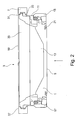
- FIG. 1 shows an inventive fastening module 3 in a perspective view.
- the fastening module 3 has a coupling closure 1 and a closure clip 7.
- the coupling closure 1 shown is one which, for example, as shown in FIG EP 1 947 039 A1 is described.
- the illustrated coupling closure 1 has a closing flap 9, a pipe socket 11, a pipe socket seal 13, as well as bearing shells 15 and 17, in which partial waves or partial-shaft stubs are present (not shown in FIG FIG. 1 ; See reference numerals 20 and 22 in FIG FIG. 3 ).
- the coupling closure 1 has a container side 19 and a closure side 21.
- the closure side 21 represents the side which is provided for coupling or docking to the closure side of a complementary coupling closure (not shown).
- the closure clip 7 is a so-called tri-clamp connection, comprising two closure clip halves 23 and 25, which are connected to one another by means of winged nuts 27 and 29 and threaded bolts 39 and 41.
- the illustrated Tri-Clamp connection allows a uniform contact pressure over the entire circumference. Viewed in cross section, the closure clip 7, as FIG. 2 can be removed, a V-shaped groove 31. Again FIG.
- the pipe socket 11 on the outside of its closure-side end on a circumferential first clamping element in the form of a projecting clamping edge 33.
- the clamping neck or flange 35 which is in connection with a container to be emptied or filled or with a conveyor (not shown), on its outer side with a circumferential second clamping element 37, also in the form of a projecting clamping edge.
- the first and second clamping elements 33 and 37 engage in the V-shaped groove 31 of the half-shells 23 and 25 of the closing clip 7. In this way, the coupling closure 1 is securely and reversibly connected to the opening of a container or Forderstoff.
- FIG. 3 shows the closure clip 7, which consists of the half-shells 23 and 25 composed, as well as the engaged coupling closure 1.
- FIG. 3 the view again, which results in the view from below on the fastening module 3 according to the invention (see arrow in FIG FIG. 2 ). Visible is also present on the outside of the pipe socket 11 circumferential first clamping element 33rd
- FIG. 4 shows a schematic exploded view of a fastening module according to the invention 3. It can be seen that the coupling closure 1 in the illustrated embodiment via a pipe socket 11, a closing flap 9, containing on both sides partial shafts, bearing shells or bearing shell units 15 and 17 for receiving the partial waves and a pipe stub 13 has ,
- the pipe stub seal 13 is equipped with a horizontally extending upper edge 43 which projects beyond the container-side end of the pipe socket 11.
- the pipe socket 11 itself has at its second, container-side end via a circumferential, extending away from the outside clamping edge 33.
- FIG. 4 The bow or half-shells 25 and 25 of the closing clip 7.
- FIG. 4 gives impressively again that the fixing module 3 according to the invention can be completely disassembled without tools. In particular, no screws are to be solved. In this way, a very uncomplicated, reliable and in particular fast assembly and disassembly of the fastening module according to the invention succeeds, so that in particular the cleaning of the coupling fasteners or fastening modules according to the invention compared to conventional systems designed substantially easier and less problematic.
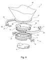
- FIG. 5 shows a second inventive coupling closure 2.
- This coupling closure 2 has a closing flap 10, a pipe socket 12, a pipe socket seal 14 and bearing shells or bearing shell units 16 and 18, in which partial shafts or Partialwellenstummel 20 and 22, which are firmly, yet removably connected to the closing flap 10, are present.
- indentations 24 and 26 are present in the partial shafts 20 and 22 in collinear alignment with the axis of rotation.
- notches form with corresponding notches in the partial shafts of a second, complementary coupling closure (not shown) engagement elements for mandrels or rods, which can be introduced into these combined notches and on, for example in conjunction with a drive shaft, the adjacent closing flaps of two to a Docking device combined coupling closures are pivotable from a closed position to an open position with the release of a transfer channel formed from the two pipe sockets of the coupling closures.
- These indentations represent an optional element of the coupling closures according to the invention. It is essential in accordance with the second inventive coupling closure according to FIG FIG. 5 the presence of a substantially semicircular groove 28 or 30 in or adjacent to the end faces of the partial shafts 20 and 22.
- grooves 28 and 30 rotate in the in FIG. 5 illustrated embodiment, at least partially, the bearing surfaces of the bearing for the partial shafts 20 and 22.
- the opposite ends of the groove open into the bearing surface of the partial shaft for the bearing surface of a partial shaft of a complementary coupling closure.
- complementary shaped spring elements 32 and 34 which are each part of the bearing shells 16 and 18 and accordingly extend in the direction of the interior of the pipe socket 12.
- closure flap 10 with the partial shafts 20 and 22 can be inserted into the cups 16 and 18 (not shown) in such a manner that the closure flap is rotated 180 ° onto the cups, in a manner in that the mutually complementary grooves and springs come into contact with each other.
- the closing flap By now turning the closing flap around its axis of rotation by 180 °, the springs engage in the complementary groove of the partial waves. In a corresponding manner, the closing flap can be removed again from the coupling closure.
Abstract
Description
Die vorliegende Erfindung betrifft einen Kupplungsverschluss zum, insbesondere umweltisolierten, Umfüllen, Befüllen und/oder Entleeren von Behältnissen sowie ein Befestigungsmodul und eine Andockeinrichtung, jeweils enthaltend diesen erfindungsgemäßen Kupplungsverschluss.The present invention relates to a coupling closure for, in particular environmentally isolated, decanting, filling and / or emptying containers as well as a fastening module and a docking device, each containing this coupling closure according to the invention.
Kupplungsverschlüsse zum kontaminationsfreien Umfüllen, Befüllen oder Entleeren von Behältnissen kommen in der weiterverarbeitenden Industrie vielfältig zum Einsatz. Solche Kupplungsverschlüsse sind auch als Halbklappen bzw. Butterflyklappen bekannt. Unter Verwendung zweier solcher komplementärer Kupplungs- bzw. Halbklappenverschlüsse erhält man bei gegenseitiger Anlage eine Andockeinrichtung, mit deren Hilfe sich auch toxisches Schüttgut in der Regel umweltisoliert transferieren lässt. Derartige Kupplungsverschlüsse und Andockeinrichtungen finden sich z.B. in der
Die Bemühungen, einen sehr hohen Grad an Kontaminationsfreiheit zu erhalten, haben sich, wie u. a. der
Um fortwährend ein Höchstmaß an Kontaminationsfreiheit zu gewährleisten, ist man insbesondere in der pharmazeutischen Industrie dazu übergegangen, die verwendeten Kupplungsverschlüsse und Andockeinrichtungen nach deren Einsatz komplett zu zerlegen und sämtliche Einzelteile zu säubern. Zur Minimierung der Gefährdung der Umwelt sind für den Fall, das toxische oder gesundheitsgefährdende Substanzen mit der Andockeinrichtung transportiert wurden, besondere Sicherheitsvorkehrungen zu treffen. Dieses Prozedere ist noch stets sehr zeit-, arbeits- und kostenaufwendig. Es wäre wünschenswert, auf solche Kupplungsverschlüsse und Andockeinrichtungen zurückgreifen zu können, die nicht mit den Nachteilen des Stands der Technik behaftet sind und eine verbesserte Reinigung erlauben.In order to continuously ensure the highest degree of freedom from contamination, it has been decided, especially in the pharmaceutical industry, to completely disassemble the coupling closures and docking devices used after their use and to clean all the individual parts. In order to minimize the risk to the environment, special safety precautions must be taken in the event that toxic or hazardous substances have been transported with the docking device. This procedure is still very time consuming, laborious and costly. It would be desirable to be able to rely on such coupling closures and docking devices, which are free from the disadvantages of the prior art and allow for improved cleaning.
Der vorliegenden Erfindung lag daher die Aufgabe zugrunde, Kupplungsverschlüsse und Andockeinrichtungen für den Transfer insbesondere toxischer Schüttgüter verfügbar zu machen, die sich schnell, ohne großen Aufwand sowie zuverlässig und mit einem Höchstmaß an Sicherheit reinigen lassen.It is an object of the present invention to provide coupling closures and docking devices for the transfer, in particular, of toxic bulk goods, which can be quickly, easily and reliably cleaned with the highest degree of safety.
Die der Erfindung zugrunde liegenden Aufgabe wird gemäß einem ersten Aspekt gelöst durch einen Kupplungsverschluss (auch erster erfindungsgemäßer Kupplungsverschluss genannt) für eine Andockeinrichtung zum, insbesondere umweltisolierten, Umfüllen, Befüllen und/oder Entleeren von Behältnissen mit einer Verschlussseite und einer Behälterseite, umfassend einen Rohrstutzen und eine darin verschwenkbar um eine Achse gelagerte Schließklappe, enthaltend eine der Verschlussseite in der Schließstellung zugewandte Stirnseite, wobei der Rohrstutzen über ein erstes, verschlussseitiges und ein gegenüberliegendes zweites, behälterseitiges Ende sowie eine Innen- und eine Außenseite verfügt und wobei die Schließklappe an dem ersten Ende vorliegt, und wobei ferner auf der Außenseite des Rohrstutzens ein, insbesondere umlaufendes, erstes Klemmelement vorliegt, geeignet und ausgelegt für die kombinierte Ineingriffnahme mit einem zweiten Klemmelement vermittels einer Verschlussklammer zwecks temporärer Verbindung.The object underlying the invention is achieved according to a first aspect by a coupling closure (also called first inventive coupling closure) for a docking device for, in particular environmentally isolated, transfer, filling and / or emptying containers with a closure side and a container side, comprising a pipe socket and a closing flap pivotally mounted therein about an axis, comprising a front side facing the closure side in the closed position, wherein the pipe socket has a first, closure-side and an opposing second, container-side end and an inner and an outer side and wherein the closing flap at the first end is present, and further provided on the outside of the pipe socket, in particular a circumferential, first clamping element, suitable and designed for the combined engagement with a second clamping element by means of a closing clip for temporary connection.
Geeignete Kupplungsverschlüsse, mit denen Andockeinrichtungen für den umweltisolierten Transfer von Schüttgut zugänglich sind, finden sich z.B. in der
Unter einer Verschlussseite im Sinne der vorliegenden Erfindung wird diejenige Seite des Kupplungsverschlusses bzw. Rohrstutzens verstanden, welche einem weiteren, komplementären Kupplungsverschluss bei Ausbildung einer Andockeinrichtung aus diesen Kupplungsverschlüssen zugewandt ist. Demgemäß stellt im Sinne der vorliegenden Erfindung die Behälterseite diejenige Seite des Kupplungsverschlusses bzw. Rohrstutzens dar, welche einem zu befüllenden oder zu entleerenden Behälter oder Fördermittel zugewandt bzw. mit einem Behälter oder Fördermittel verbunden ist.Under a closure side according to the present invention, that side of the coupling closure or pipe socket is understood, which another, complementary Coupling closure faces in training a docking of these coupling closures. Accordingly, in the context of the present invention, the container side is that side of the coupling closure or pipe socket which faces a container or conveying means to be filled or emptied or is connected to a container or conveying means.
Das erste Klemmelement liegt vorzugsweise auf der Außenseite an dem zweiten Ende des Rohrstutzens, d.h. an dem behälterseitigen Ende desselben vor. Das erste Klemmelement stellt vorzugsweise einen von der Außenseite des Rohrstutzens vorspringenden Klemmrand dar, beispielsweise eine, vorzugsweise umlaufende, Feder. Beispielsweise kann das erste Klemmelement unmittelbar am Rand des Rohrstutzens vorliegen. Alternativ ist es ebenfalls möglich, dass das erste Klemmelement auf der Außenseite des Rohrstutzens beabstandet von dem Rand des Rohrstutzens, insbesondere umlaufend, vorliegt. Der Abstand des ersten Klemmelements von dem Rand des Rohrstutzens an dem zweiten Ende desselben ist zweckmäßigerweise in Abhängigkeit von den Dimensionen der Verschlussklammer zu wählen, um über eine In-eingriffnahme des ersten Klemmelements und eines weiteren, zweiten Klemmelements eine feste Verbindung herstellen zu können.The first clamping element is preferably on the outside at the second end of the pipe socket, i. at the container end of the same front. The first clamping element preferably represents a protruding from the outside of the pipe socket clamping edge, for example, a preferably circumferential, spring. For example, the first clamping element can be present directly on the edge of the pipe socket. Alternatively, it is also possible that the first clamping element on the outside of the pipe socket spaced from the edge of the pipe socket, in particular circumferential, is present. The distance of the first clamping element from the edge of the pipe socket at the second end thereof is expediently to be selected as a function of the dimensions of the closing clip in order to be able to establish a firm connection by engaging the first clamping element and a further, second clamping element.
Des Weiteren kann vorgesehen sein, dass die Schließklappe in Verbindung mit mindestens einer Welle, beispielsweise einer Antriebswelle, steht.Furthermore, it can be provided that the closing flap is in connection with at least one shaft, for example a drive shaft.
Erfindungsgemäße Kupplungsverschlüsse zeichnen sich gemäß einer weiteren Ausgestaltung auch dadurch aus, dass die Schließklappe an mindestens einer Seite, insbesondere auf beiden Seiten, längs der Achse mit einer Partialwelle oder einem Partialwellenstummel in jeweils zur Verschlussseite hin offenem Lager gelagert ist, wobei die Partialwelle(n) oder - wellenstummel geeignet ist (sind), um bei Anlage mit komplementären Partialwellen bzw. - wellenstummeln eines weiteren Kupplungsverschlusses eine Welle oder einen Wellenstummel auszubilden, wobei die Partialwelle oder der -wellenstummel mit mindestens einem Eingriffselement ausgestattet ist, in das ein komplementäres Eingriffselement, das in Wirkverbindung mit einem Antrieb bringbar ist oder steht, einführbar ist.According to a further embodiment, coupling closures according to the invention are also distinguished by the fact that the closing flap is mounted on at least one side, in particular on both sides, along the axis with a partial shaft or a partial stub shaft in each case open towards the closure side, wherein the partial shaft (s) or stub shaft is adapted to form a shaft or stub shaft upon engagement with complementary partial shaft stubs of another coupler seal, the partial shaft or stub shaft being provided with at least one engagement element into which a complementary engagement element, in operative connection with a drive can be brought or is, is insertable.
Ferner kann gemäß einer weiteren Ausführungsform der Rohrstutzen innenseitig zumindest bereichsweise, insbesondere voll-umfänglich, mit einer Rohrstutzendichtung ausgestattet sein. Des Weiteren ist es möglich, die Schließklappe in der Rohrstutzendichtung zu lagern. In einer besonders bevorzugten Ausgestaltung zeichnet sich der erfindungsgemäße Kupplungsverschluss dadurch aus, dass die Rohrstutzendichtung sich zumindest abschnittsweise über das zweite Ende des Rohrstutzens hinaus erstreckt.Furthermore, according to a further embodiment of the pipe socket on the inside at least partially, in particular full-circumference, be equipped with a pipe socket seal. Furthermore, it is possible to store the closing flap in the pipe socket seal. In a Particularly preferred embodiment, the coupling closure according to the invention is characterized in that the pipe socket seal extends at least in sections beyond the second end of the pipe socket.
Hierbei kann z.B. auch vorgesehen sein, dass die Schließklappe auf ihrer Außenseite mit mindestens einem Dichtungsabschnitt oder mindestens einer, insbesondere umlaufenden, Dichtung versehen ist, die zumindest abschnittsweise am oder benachbart zum Umfangsrand angeordnet ist. In einer weiteren zweckmäßigen Ausgestaltung ist vorgesehen, dass die Schließklappe auf ihrer Außenseite mit mindestens einem Dichtungsabschnitt oder mindestens einer, insbesondere umlaufenden, Dichtung versehen ist, die zumindest abschnittsweise am oder benachbart zum Umfangsrand angeordnet ist. Des Weiteren ist es möglich, die Schließklappe in der Rohrstutzendichtung zu lagern.Here, e.g. Also be provided that the closing flap is provided on its outside with at least one sealing portion or at least one, in particular circumferential, seal, which is at least partially disposed on or adjacent to the peripheral edge. In a further expedient embodiment it is provided that the closing flap is provided on its outside with at least one sealing portion or at least one, in particular circumferential, seal, which is at least partially disposed on or adjacent to the peripheral edge. Furthermore, it is possible to store the closing flap in the pipe socket seal.
Eine weitere zweckmäßige Ausgestaltung sieht vor, dass die Stirnseite der Schließklappe in der Schließstellung zumindest abschnittsweise mit dem der Verschlussseite zugewandten Rand des Rohrstutzens oder der Rohrstutzendichtung im Wesentlichen fluchtend anordbar oder angeordnet ist.A further expedient embodiment provides that the end face of the closing flap in the closed position, at least in sections, can be arranged or arranged substantially flush with the edge of the pipe socket or pipe socket seal facing the closure side.
Erfindungsgemäße Kupplungsverschlüsse beinhalten auch solche Ausführungsformen, bei denen diese Kupplungsverschlüsse bzw. deren Rohrstutzen behälterseitig dichtend verbindbar oder verbunden mit einem Behälter oder einem Fördermittel vorliegen.
Das Lager, die Lagerschale bzw. die Lagerschaleneinheit, insbesondere jedoch zumindest die Lagerschale sind auch bei dem zweiten erfindungsgemäßen Kupplungsverschluss, mindestens bereichsweise, insbesondere vollständig, aus mindestens einem Kunststoffmaterial, insbesondere aus Polyamid, Polyetherketon (PEK), Polyetheretherketon (PEEK), Polyetherimid, Polybutylenterephthalat (PBT), Polyketonen, Polyimiden, Polyphenylenether, Polyaryletherketonen, Polyacrylnitril, Polyvinylchlorid, Polyolefinen und/oder Polyoxymethylen, gefertigt sind. Im Sinne der vorliegenden Erfindung umfasst das zur Verschlussseite hin offene Lager die Lagerschale, in der die Partialwelle bzw. der Partialwellenstummel drehbar gelagert aufliegt. Das Lager und damit auch die Lagerschale können Bestandteil einer so genannten Lagerschaleneinheit sein. Diese Lagerschaleneinheit kann ein separates bzw. von dem Rohrstutzen separierbares Bauteil sein.Coupling closures according to the invention also include those embodiments in which these coupling closures or their pipe stubs are sealingly connectable on the container side or connected to a container or a conveying means.
The bearing, the bearing shell or the bearing shell unit, but in particular the bearing shell are also in the second coupling closure according to the invention, at least partially, in particular completely, at least one plastic material, in particular polyamide, polyether ketone (PEK), polyetheretherketone (PEEK), polyetherimide, Polybutylene terephthalate (PBT), polyketones, polyimides, polyphenylene ethers, polyaryletherketones, polyacrylonitrile, polyvinyl chloride, polyolefins and / or polyoxymethylene, are made. For the purposes of the present invention, the bearing open towards the closure side comprises the bearing shell in which the partial shaft or the partial shaft stub rests rotatably mounted. The bearing and thus also the bearing shell can be part of a so-called bearing shell unit. This bearing shell unit may be a separate or separable from the pipe socket component.
Gemäß einem weiteren Aspekt der vorliegenden Erfindung wird das zugrunde liegende Problem gelöst durch ein Befestigungsmodul, umfassend einen erfindungsgemäßen Kupplungsverschluss sowie eine Verschlussklammer, geeignet und ausgelegt zur kombinierten Ineingriffnahme des ersten Klemmelements mit einem zweiten, komplementären Klemmelement zwecks temporären Verbindung.According to a further aspect of the present invention, the underlying problem is solved by a fastening module comprising a coupling closure according to the invention and a closure clip, suitable and adapted for combined engagement of the first clamping element with a second, complementary clamping element for the purpose of temporary connection.
In einer bevorzugten Ausgestaltung verfügt das erfindungsgemäße Befestigungsmodul ferner über einen Klemmstutzen, insbesondere Flansch, mit einem ersten Ende und einem gegenüberliegenden zweiten Ende und einer Innen- und einer Außenseite, wobei auf der Außenseite, insbesondere am zweiten Ende, das, insbesondere umlaufende, zweite Klemmelement vorliegt. Das zweite Ende des Klemmstutzens ist demgemäß bei Einsatz der Verschlussklammer benachbart zur Behälterseite bzw. dieser zugewandt.In a preferred embodiment, the fastening module according to the invention further comprises a clamping piece, in particular flange, with a first end and an opposite second end and an inner and an outer side, wherein on the outer side, in particular at the second end, the, in particular circumferential, second clamping element is present. The second end of the clamping nozzle is accordingly adjacent to the container side or facing the container side when using the closing clip.
Als besonders zweckmäßig und bedienfreundlich haben sich solche erfindungsgemäßen Befestigungsmodule erwiesen, bei denen der Rohrstutzen des Kupplungsverschlusses über eine Rohrstutzendichtung verfügt, die sich zumindest abschnittsweise, insbesondere vollumfänglich, über das zweite, behälterseitige Ende des Rohrstutzens hinaus erstreckt.Be particularly useful and easy to use such fastening modules according to the invention have proven in which the pipe socket of the coupling closure has a pipe socket seal, which extends at least partially, in particular full circumference, on the second, container-side end of the pipe socket addition.
In einer ersten Weiterentwicklung umfasst das erfindungsgemäße Befestigungsmodul ferner einen Behälter mit einer Umfüll-, Befüll- oder Entleeröffnung oder ein Fördermittel mit einer Umfüll-, Befüll- oder Entleeröffnung, insbesondere einen Schlauch oder ein Rohr, jeweils mit einer Außen- und einer Innenseite, wobei auf der Außenseite des Behälters oder des Fördermittels das, insbesondere umlaufende, zweite, komplementäre Klemmelement, insbesondere als integraler Bestandteil des Behälters oder Fördermittels, vorliegt.In a first development, the fastening module according to the invention further comprises a container with a transfer, filling or emptying opening or a conveying means with a transfer, filling or emptying opening, in particular a hose or a tube, each with an outer and an inner side, wherein on the outside of the container or the conveying means the, in particular circumferential, second, complementary clamping element, in particular as an integral part of the container or conveying means, is present.
Gemäß einer zweiten Weiterentwicklung umfasst das erfindungsgemäße Befestigungsmodul ferner einen Behälter mit einer Umfüll-, Befüll- oder Entleeröffnung oder ein Fördermittel mit einer Umfüll-, Befüll- oder Entleeröffnung, insbesondere einen Schlauch oder ein Rohr, sowie einen Klemmstutzen, insbesondere Flansch, welcher mit dem Behälter oder Fördermittel verbunden oder integraler Bestandteil derselben ist, und der über ein erstes, dem Behälter oder Fördermittel zugewandtes Ende und ein gegenüberliegendes zweites, dem Kupplungsverschluss zugewandtes oder zuwendbares Ende sowie über eine Innen- und eine Außenseite verfügt, wobei auf der Außenseite, insbesondere am zweiten Ende, das, insbesondere umlaufende, zweite Klemmelement, insbesondere als integraler Bestandteil des Klemmstutzens, vorliegt.According to a second further development, the fastening module according to the invention further comprises a container with a decanting, filling or emptying opening or a conveying means with a decanting, filling or emptying opening, in particular a hose or a pipe, and a clamping piece, in particular flange, which is connected to the Container or conveying means connected or integral part thereof, and which has a first, the container or conveying end facing and an opposite second, the coupling closure facing or zuwendbares end and on an inner and an outer, wherein on the outside, in particular on second end, which, in particular circumferential, second clamping element, in particular as an integral part of the clamping piece, is present.
Als besonders zweckmäßig hat sich eine solche Ausführungsform eines erfindungsgemäßen Befestigungsmoduls erwiesen, bei der die Umfüll-, Befüll- oder Entleeröffnung des Behälters oder des Fördermittels in ihrer Dimensionierung im Wesentlichen komplementär zu dem sich über den Rohrstutzen hinaus erstreckenden Ende der Rohrstutzendichtung ist und wobei das sich über den Rohrstutzen hinaus erstreckenden Ende der Rohrstutzendichtung und die Umfüll-, Befüll- oder Entleeröffnung geeignet und ausgelegt sind, um bei Ineingriffnahme von erstem und zweitem Klemmelement durch die Verschlussklammer in dichtendem Kontakt zu treten.Be particularly useful such an embodiment of a fastening module according to the invention has proven, in which the Umfüll-, filling or emptying opening of the container or the conveyor in its dimensions is substantially complementary to the extending beyond the pipe socket end of the pipe socket seal and wherein the extending beyond the pipe stub end of the pipe stub seal and the Umfüll-, Befüll- or emptying opening are suitable and designed to come in engagement with the first and second clamping element by the closure clip in sealing contact.
In gleicher Weise stellt sich eine solche Ausführungsform als besonders zweckmäßig dar, bei der das zweite Ende des Klemmstutzens in seiner Dimensionierung im Wesentlichen komplementär zu dem sich über den Rohrstutzen hinaus erstreckenden Ende der Rohrstutzendichtung ist und wobei das sich über den Rohrstutzen hinaus erstreckenden Ende der Rohrstutzendichtung und das zweite Ende des Klemmstutzens geeignet und ausgelegt sind, um bei Ineingriffnahme von erstem und zweitem Klemmelement durch die Verschlussklammer in dichtendem Kontakt zu treten.In the same way, such an embodiment is particularly expedient, in which the second end of the clamping piece is in its dimensioning substantially complementary to the extending beyond the pipe stub end of the pipe stub seal and wherein the extending beyond the pipe stub end of the pipe stub seal and the second end of the grommet are adapted and adapted to make sealing contact when the first and second clamping members are engaged by the locking clip.
Die beiden vorangehend genannten besonders zweckmäßigen Ausgestaltungen haben u.a. den Vorteil, die Anzahl der Bauteilkomponenten der erfindungsgemäßen Befestigungsmodule sehr gering halten zu können. Interessanterweise wird durch diese Minimierung der Bauteile die Umweltdichtigkeit beim Transfer von Schüttgut nicht beeinträchtigt. Vielmehr wird ein noch höheres Maß an Bediensicherheit erhalten. Beispielsweise wird die Gefahr verringert, Bauteile mit Schüttgut zu kontaminieren, was bislang regelmäßig die Demontage und Reinigung aufwendiger gestaltet hat.The two above-mentioned particularly expedient embodiments have u.a. the advantage of being able to keep very low the number of component components of the fastening modules according to the invention. Interestingly, this minimization of components does not affect the environmental integrity of the transfer of bulk material. Rather, an even higher level of operating safety is obtained. For example, the risk is reduced to contaminate components with bulk material, which has been regularly designed disassembly and cleaning more expensive.
Des weiteren sind auch solche erfindungsgemäßen Befestigungsmodule gemäß den vorangehend genannten ersten und zweiten Weiterentwicklungen umfasst, bei denen der Behälter oder das Fördermittel an der Umfüll-, Befüll- oder Entleeröffnung eine zumindest abschnittsweise, insbesondere umlaufende, Dichtung aufweist, die komplementär ist zu dem sich über den Rohrstutzen hinaus erstreckenden Ende der Rohrstutzendichtung und die geeignet und ausgelegt ist, um bei Ineingriffnahme von erstem und zweitem Klemmelement durch die Verschlussklammer mit der Rohrstutzendichtung in dichtendem Kontakt zu treten.Furthermore, such fastening modules according to the invention according to the above-mentioned first and second developments are also included, in which the container or the conveying means at the Umfüll-, filling or emptying an at least partially, in particular circumferential seal, which is complementary to the on the pipe socket extending beyond the pipe socket seal and the suitable and is designed to, upon engagement of the first and second clamping element by the closure clip with the pipe socket seal in sealing contact.
Darüber hinaus sind auch solche erfindungsgemäßen Befestigungsmodule mit umfasst, bei denen der Klemmstutzen an dem zweiten Ende eine zumindest abschnittsweise, insbesondere umlaufende, Dichtung aufweist, die komplementär zu dem sich über den Rohrstutzen hinaus erstreckenden Ende der Rohrstutzendichtung ist und die geeignet und ausgelegt ist, um bei Ineingriffnahme von erstem und zweitem Klemmelement durch die Verschlussklammer mit der Rohrstutzendichtung in dichtenden Kontakt zu treten.In addition, such fastening modules according to the invention are also included, in which the clamping piece at the second end has an at least partially, in particular circumferential, seal which is complementary to the extending beyond the pipe socket end of the pipe socket seal and which is suitable and designed to order Upon engagement of the first and second clamping element by the closure clip with the pipe socket seal in sealing contact.
Indem bei den vorangehend geschilderten Ausführungsformen einerseits die Rohrstutzendichtung über das zweite Ende des Rohrstutzens hervorsteht und andererseits ebenfalls die Öffnung des Behälters, Fördermittels oder Klemmstutzens bzw. die Dichtung an der Öffnung des Behälters oder Fördermittels derart ausgestaltet sind, dass diese mit der überstehenden Dichtung in Kontakt bringbar sind, kann allein über die Verschlussklammer beim Verschließen derselben durch Ineingriffnahme der, insbesondere umlaufenden, ersten und zweiten Klemmelemente, beispielsweise in Form von so genannten Federn bzw. Vorsprüngen, ein Aneinanderpressen der genannten Öffnung mit der überstehenden Dichtung bzw. der beiden genannten Dichtungen bewirkt werden. Hierbei ist von Vorteil, dass auf einen zusätzlichen Dichtungsring, beispielsweise ein O-Ring, zwischen dem ersten und zweiten Klemmelement vollständig verzichtet werden kann.By protruding in the above-described embodiments, on the one hand, the pipe socket seal over the second end of the pipe socket and on the other hand also the opening of the container, conveyor or Klemmstutzens or the seal at the opening of the container or conveyor are designed such that it with the protruding seal in contact Can be brought alone by the closure clip when closing the same by engaging the, in particular rotating, first and second clamping elements, for example in the form of so-called springs or projections, a pressing together said opening with the protruding seal or the two said seals causes become. It is advantageous that can be completely dispensed with an additional sealing ring, such as an O-ring between the first and second clamping element.
Zur Erhöhung der Dichtigkeit zwischen dem ersten und zweiten Klemmelement kann gleichwohl ferner mindestens ein Dichtungsring vorgesehen sein, der geeignet und ausgelegt ist zur dichtenden Anlage zwischen den erstem und den zweiten Klemmelement.In order to increase the tightness between the first and second clamping element, at least one sealing ring may nevertheless be provided, which is suitable and designed for sealing contact between the first and the second clamping element.
In einer weiteren Ausführungsform kann vorgesehen sein, dass das erste Klemmelement einen Nutklemmstutzen und das zweite Klemmelement einen Bundklemmstutzen darstellt oder umfasst oder Bestandteil hiervon ist. Alternativ kann vorgesehen sein, dass das erste Klemmelement einen Bundklemmstutzen und das zweite Klemmelement einen Nutklemmstutzen darstellt oder umfasst oder Bestandteil hiervon ist.In a further embodiment, it can be provided that the first clamping element is a groove clamping nozzle and the second clamping element is a collar clamping piece or comprises or is part of this. Alternatively it can be provided that the first clamping element is a collar clamp and the second clamping element is a Nutklemmstutzen or comprises or is part of this.
Die bei dem erfindungsgemäßen Befestigungsmodul zum Einsatz kommende Verschlussklammer stellt vorzugsweise eine Spannklammer, insbesondere nach DIN 32676, oder einen Schnellverschluss dar. Besonders bevorzugt werden als Verschlussklammern so genannte Tri-Clamp-Verschlüsse verwendet. Hierbei kann beispielsweise auf so genannte Eingelenk- und Zweigelenk-Tri-Clamp-Verschlüsse zurückgegriffen werden. Diese Ein- und Zweigelenksysteme verfügen jeweils über zwei Halbschalen bzw. Bügelelemente. Des Weiteren können auch dreiteilige Tri-Clamp-Gelenkklammersysteme zum Einsatz kommen. Gelenk und Verschluss bzw. Schnellverschluss liegen bei den Eingelenk- und Zweigelenksystemen regelmäßig einander gegenüber. Im Querschnitt betrachtet verfügen die Halb- bzw. Teilschalen, die die Verschlussklammer bzw. die Tri-Clamp-Verbindung bilden über eine V-förmige Nut. In einer Ausführungsform wird der Verschluss bzw. Schnellverschluss durch eine Verschlussschraube und eine Gewindemutter gebildet. Die Verschlussschraube ist vorzugsweise schwenkbar an einem Achsbolzen der einen Halbschale gelagert.The closure clip used in the fastening module according to the invention preferably provides a clamping clip, in particular according to DIN 32676, or a Quick release is particularly preferred as a closure clips so-called tri-clamp closures used. In this case, for example, so-called single joint and double joint tri-clamp closures can be used. These single and double steering systems each have two half shells or bracket elements. Furthermore, three-piece Tri-Clamp joint clamp systems can also be used. Joint and closure or quick release are regularly opposed to each other in the single-joint and two-joint systems. Viewed in cross-section, the half-shells or partial shells which form the closure clip or the tri-clamp connection have a V-shaped groove. In one embodiment, the closure or rapid closure is formed by a closure screw and a threaded nut. The locking screw is preferably pivotally mounted on a pivot pin of a half-shell.
Bei der Montage der Verschlussklammer bzw. des Tri-Clamp-Verschlusses ergreifen die ersten und zweiten Klemmelemente, beispielsweise in Form hervorstehender Außenränder in die V-förmige Nut der Halb- bzw. Teilschalen der Verschlussklammer ein. Anschließend kann die Verschlussschraube in die Verschlussposition geschwenkt werden. Durch Festdrehen der Gewindemutter können die ersten und zweiten Klemmelemente koaxial fest gegeneinander gedrückt werden, so dass eine dichte Verbindung entsteht.During assembly of the closing clip or the tri-clamp closure, the first and second clamping elements, for example in the form of protruding outer edges, engage in the V-shaped groove of the half or partial shells of the closing clip. Subsequently, the screw plug can be pivoted into the closed position. By tightening the threaded nut, the first and second clamping elements can be coaxially pressed firmly against each other, so that a tight connection is formed.
In einer besonders vorteilhaften Ausführungsform eines erfindungsgemäßen Befestigungsmoduls ist vorgesehen, dass der Klemmstutzen, insbesondere der zweite Flansch, einen, insbesondere integralen, Bestandteil eines Behälters, Containers oder Fördermittels, insbesondere Schlauches, darstellt.In a particularly advantageous embodiment of a fastening module according to the invention it is provided that the clamping piece, in particular the second flange, one, in particular integral, part of a container, container or conveying means, in particular hose represents.
Die der Erfindung zugrunde liegende Aufgabe wird gemäß einem weiteren Aspekt gelöst durch eine Andockeinrichtung zum, insbesondere umweltisolierten, Umfüllen, Befüllen und/oder Entleeren von Behältnissen (erste erfindungsgemäße Andockeinrichtung), umfassend einen erfindungsgemäßen ersten Kupplungsverschluss oder ein erfindungsgemäßen Befestigungsmodul sowie einen weiteren, zum ersten Kupplungsverschluss komplementären zweiten Kupplungsverschluss mit einer Verschlussseite und einer Behälterseite, umfassend einen zweiten Rohrstutzen und eine darin verschwenkbare um eine Achse gelagerte Schließklappe, enthaltend eine der Verschlussseite in der Schließstellung zugewandte Stirnseite, wobei die Stirnseiten der Schließklappen von erstem und zweitem Kupplungsverschluss aneinander anliegen oder aneinander zur Anlage bringbar sind und in aneinander angelegtem Zustand aus einer Schließstellung, in der sie den durch den Rohrstutzen des ersten Kupplungsverschlusses und den Rohrstutzen des zweiten Kupplungsverschlusses gebildeten Transferkanal verschließen, um eine gemeinsame Achse in eine Öffnungsstellung verschwenkbar sind. Hierbei beinhaltet das erfindungsgemäße Befestigungsmodul auch den erfindungsgemäßen ersten Kupplungsverschluss.The object underlying the invention is achieved according to a further aspect by a docking device for, in particular environmentally isolated, transfer, filling and / or emptying of containers (first docking device according to the invention), comprising a first coupling closure according to the invention or a fastening module according to the invention and another, to the first Clutch closure complementary second coupling closure with a closure side and a container side, comprising a second pipe socket and a pivotally mounted therein about an axis closing flap, containing one of the closure side in the closed position facing end side, the end faces of the closing flaps of the first and second coupling closure abut each other or to each other Plant can be brought and in an attached state from a closed position in which they close the transfer channel formed by the pipe socket of the first coupling closure and the pipe socket of the second coupling closure, are pivotable about a common axis into an open position. In this case, the fastening module according to the invention also includes the first coupling closure according to the invention.
Geeignete Andockeinrichtungen finden sich z.B. in der
Hierbei kann in einer zweckmäßigen Ausgestaltung der erfindungsgemäßen Andockeinrichtung vorgesehen sein, dass die Rohrstutzen, insbesondere die Rohrstutzendichtungen, von erstem und zweitem Kupplungsverschluss bei Anlage derselben gegeneinander bündig abschließen.Here, in an expedient embodiment of the docking device according to the invention can be provided that the pipe socket, in particular the pipe socket seals, of the first and second coupling closure in the same system flush against each other.
Vorteilhafterweise sind bei der erfindungsgemäßen Andockeinrichtung die Schließklappen von ersten und zweiten Kupplungsverschluss im Wesentlichen kreisförmig ausgebildet.Advantageously, in the docking device according to the invention, the closing flaps of the first and second coupling fastener are substantially circular.
Ferner kann die erfindungsgemäße Andockeinrichtung mit mindestens einer Antriebswelle die in Wirkverbindung mit einem Antrieb steht, ausgestattet sein.Furthermore, the docking device according to the invention can be equipped with at least one drive shaft which is in operative connection with a drive.
In den vorangehend beschriebenen erfindungsgemäßen Andockeinrichtungen kann selbstverständlich auch der zweite Kupplungsverschluss einen erfindungsgemäßen Kupplungsverschluss (erster erfindungsgemäßer Kupplungsverschluss) darstellen oder umfassen.Of course, in the above-described docking devices according to the invention, the second coupling closure may also represent or comprise a coupling closure according to the invention (first coupling closure according to the invention).
Der vorliegenden Erfindung liegt die überraschende Erkenntnis zugrunde, dass sich bei Verwendung der erfindungsgemäßen Kupplungsverschlüsse, Befestigungsmodule und Andockeinrichtungen das Reinigungsprozedere nach einem Schüttguttransfer erheblich vereinfachen lässt. Beispielsweise kann die für die Demontage und Montage aufzuwendende Zeit gegenüber herkömmlichen Schüttguttransfersystemen um ein Vielfaches reduziert werden. Außerdem gestatten der erfindungsgemäße Kupplungsverschluss, das erfindungsgemäße Befestigungsmodul und die erfindungsgemäße Andockeinrichtung, das Kontaminationsrisiko nochmals zu verringern und gleichzeitig die Bediensicherheit erheblich zu erhöhen. So kommt man gegenüber herkömmlichen Systemen mit weitaus weniger Bauteilen aus. Diesbezüglich stellt sich ein Vorteil insbesondere gegenüber solchen Schüttguttransfersystemen ein, bei denen ein Kupplungsverschluss bzw. eine Halbklappe fest, beispielsweise über eine Vielzahl an Schrauben, mit einem zu entleerenden oder zu befüllenden Behältnis zu verbunden sein hatte.The present invention is based on the surprising finding that, when using the coupling closures according to the invention, fastening modules and docking devices, the cleaning procedure can be considerably simplified after a bulk material transfer. For example, the time required for disassembly and assembly can be reduced many times over conventional bulk material transfer systems. In addition, the coupling closure according to the invention, the fastening module according to the invention and the docking device according to the invention allow to further reduce the risk of contamination and at the same time significantly increase operating safety. This means that you can get by with far fewer components than conventional systems. In this regard, an advantage arises, in particular, with respect to bulk material transfer systems in which a coupling closure or a half-flap, for example, had to be connected to a container to be emptied or filled via a plurality of screws.
Eine separate Weiterentwicklung eines Kupplungsverschlusses für eine Andockeinrichtung zum, insbesondere umweltisolierten Umfüllen, Befüllen oder Entleeren von Behältnissen oder Fördermitteln (auch zweiter erfindungsgemäßer Kupplungsverschluss genannt) ist ausgestattet mit einer Verschlussseite und einer Behälterseite, umfassend einen Rohrstutzen und eine darin verschwenkbar um eine Achse gelagerte Schließklappe, enthaltend eine der Verschlussseite in der Schließstellung zugewandte Stirnseite, wobei die Schließklappe an mindestens einer Seite, insbesondere auf beiden Seiten, längs der Achse mit einer Partialwelle oder einem Partialwellenstummel in jeweils zur Verschlussseite hin offenem Lager, insbesondere umfassend eine Lagerschale, gelagert ist, wobei die Partialwelle(n) oder -wellenstummel geeignet ist (sind), um bei Anlage mit komplementären Partialwellen bzw.- wellenstummeln eines weiteren, komplementären Kupplungsverschlusses eine Welle oder einen Wellenstummel auszubilden, wobei, dass mindestens eine Partialwelle oder mindestens ein Partialwellenstummel in der Stirnfläche, vorzugsweise beide Partialwellen bzw.- wellenstummel, mindestens eine teilkreisförmige, insbesondere halbkreisförmige Führungsnut aufweist, deren einander gegenüberliegende Enden sich jeweils bis zur Auflagefläche für eine komplementäre Partialwelle bzw. einen komplementären Partialwellenstummel eines weiteren Kupplungsverschlusses erstrecken, und dass das zur Verschlussseite hin offene Lager mindestens eine in das Innere des Rohrstutzens weisende teilkreisförmige, insbesondere halbkreisförmige, Führungsschiene aufweist, welche im wesentlichen komplementär ist zu der Führungsnut in der Stirnfläche der Partialwelle oder des Partialwellenstummels, wobei die Führungsnut und die dazu komplementäre Führungsschiene geeignet und ausgelegt sind, um beim Verschwenken der Schließklappe von der Schließstellung in die Offenstellung formschlüssig ineinander zu greifen, wobei dass das zur Verschlussseite hin offene Lager mindestens eine in das Innere des Rohrstutzens weisende teilkreisförmige, insbesondere halbkreisförmige, Führungsnut aufweist, deren einander gegenüberliegende Enden sich jeweils bis zur Auflagefläche für eine komplementäre Partialwelle bzw. einen komplementären Partialwellenstummel eines weiteren Kupplungsverschlusses erstrecken, und dass mindestens eine Partialwelle oder mindestens ein Partialwellenstummel in der Stirnfläche, vorzugsweise beide Partialwellen bzw.- wellenstummel, mindestens eine teilkreisförmige, insbesondere halbkreisförmige Führungsschiene aufweist, welche im wesentlichen komplementär ist zu der Führungsnut in dem Lager, wobei die Führungsnut und die dazu komplementäre Führungsschiene geeignet und ausgelegt sind, um beim Verschwenken der Schließklappe von der Schließstellung in die Offenstellung formschlüssig ineinander zu greifen.A separate development of a coupling closure for a docking device for, in particular environmentally isolated transfer, filling or emptying of containers or conveyors (also called second inventive coupling closure) is equipped with a closure side and a container side, comprising a pipe socket and a pivotally mounted therein about an axis closing flap containing the closure side facing the closed position in the closed position, wherein the closing flap is mounted on at least one side, in particular on both sides, along the axis with a partial shaft or a Partialwellenstummel in each case towards the closure side open bearing, in particular comprising a bearing shell, wherein the Partial shaft (s) or shaft stub is (are) suitable for a system with complementary partial waves or -schwellenstummeln another, complementary coupling closure a shaft or stub shaft ubilden, wherein that at least one partial shaft or at least one partial shaft stub in the end face, preferably both Partialwellen bzw.- stub shaft, at least one part-circular, in particular semicircular guide groove, whose opposite ends each up to the support surface for a complementary partial wave or a complementary Partialwellenstummel another coupling closure extend, and that the bearing open to the closure side has at least one pointing into the interior of the pipe socket part-circular, in particular semicircular, guide rail, which is substantially complementary to the guide groove in the end face of the partial shaft or the partial shaft stub, wherein the guide and the complementary thereto guide rail are suitable and designed to interlock positively when pivoting the closing flap from the closed position into the open position, wherein that the bearing open to the closure side bearing at least one pointing into the interior of the pipe socket part-circular, in particular semicircular guide groove, whose opposite ends each extend to the support surface for a complementary partial shaft or a complementary partial shaft stub of another coupling closure, and that at least a partial shaft or at least a partial shaft stub in the end face, preferably both partial shaft or stub shaft, at least one part-circular, in particular semicircular guide rail which is substantially complementary to the guide groove in the bearing, wherein the guide groove and the complementary guide rail suitable and designed are at the Swiveling the closing flap from the closed position to the open position to engage in a form-fitting manner.
Im Sinne der vorliegenden Erfindung umfasst das zur Verschlussseite hin offene Lager die Lagerschale, in der die Partialwelle bzw. der Partialwellenstummel drehbar gelagert aufliegt. Das Lager und damit auch die Lagerschale können Bestandteil einer so genannten Lagerschaleneinheit sein. Diese Lagerschaleneinheit kann ein separates bzw. von dem Rohrstutzen separierbares Bauteil sein. Vorzugsweise ist hierbei mindestens eine bzw. sind insbesondere beide Lagerschaleneinheiten reversibel trennbar mit den Rohrstutzen verbunden oder verbindbar.For the purposes of the present invention, the bearing open towards the closure side comprises the bearing shell in which the partial shaft or the partial shaft stub rests rotatably mounted. The bearing and thus also the bearing shell can be part of a so-called bearing shell unit. This bearing shell unit may be a separate or separable from the pipe socket component. Preferably, in this case at least one or in particular both bearing shell units are reversibly separable connected to the pipe socket or connectable.
Durch die formschlüssige Lagerung bzw. Verbindung von mindestens einem Lager mit mindestens einer Partialwelle, vorzugsweise von beiden Lagern mit den korrespondierenden Partialwellen oder -wellenstummeln erhält man einen zweiten erfindungsgemäßen Kupplungsverschluss, bei dem die Schließklappe auch im Dauerbetrieb unverlierbar mit dem Rohrstutzen bzw. den Kupplungsverschluss verbunden bleibt. Überraschenderweise wird diese Zunahme an Betriebsicherheit ohne zusätzliche weitere Bauteile erreicht. Ganz im Gegenteil stellt sich dieser erfindungsgemäße Kupplungsverschluss als ein solcher dar, der mit einer sehr geringen Anzahl an Einzelkomponenten gleichwohl einen kontaminationsfreien Transfer von Schüttgut gewährleistet.Due to the positive storage or connection of at least one bearing with at least one partial shaft, preferably from both bearings with the corresponding partial shafts or -wellenstummeln obtained a second coupling closure according to the invention, in which the closing flap permanently connected in captive operation with the pipe socket or the coupling closure remains. Surprisingly, this increase in operational safety is achieved without additional components. On the contrary, this coupling closure according to the invention presents itself as such, which nevertheless ensures a contamination-free transfer of bulk material with a very small number of individual components.
Hierbei kann des Weiteren vorgesehen sein, dass die Führungsnut und die Führungsschiene zueinander komplementäre formschlüssige Ineingriffnahmeelemente aufweisen, so dass eine relative Axialbewegung von Partialwelle bzw. -wellenstummel und Lager unterbunden wird bzw. unterbindbar ist.In this case, it can further be provided that the guide groove and the guide rail have mutually complementary positive engaging elements, so that a relative axial movement of partial shaft or shaft stub and bearing is prevented or can be prevented.
Dieser zweite erfindungsgemäße Kupplungsverschluss stellt z.B. eine Weiterentwicklung der in der
Gemäß einer Ausführungsform zeichnet sich der erfindungsgemäße Kupplungsverschluss dadurch aus, dass die Partialwelle oder der Partialwellenstummel mit mindestens einem Eingriffselement ausgestattet ist, in das ein komplementäres Eingriffselement, das in Wirkverbindung mit einem Antrieb bringbar ist oder steht, einführbar ist. Somit stellt der zweite erfindungsgemäße Kupplungsverschluss auch eine Weiterentwicklung der in der
Ferner ist es möglich, auf den Rohrstutzen des zweiten erfindungsgemäßen Kupplungsverschlusses innenseitig zumindest bereichsweise, insbesondere vollumfänglich, mit einer Rohrstutzendichtung auszustatten. Ferner kann vorgesehen sein, dass in Schließstellung die Stirnseite der Schließklappe und die nicht in dem Lager gelagerte, insbesondere abgeflachte, Seite der Partialwelle bzw. Partialwellenstummels zumindest bereichsweise fluchtend angeordnet oder angeordnet sind.Furthermore, it is possible on the pipe socket of the second coupling closure according to the invention on the inside at least partially, in particular full circumference, equip with a pipe socket seal. Furthermore, it can be provided that in the closed position, the end face of the closing flap and the not mounted in the bearing, in particular flattened, side of the partial shaft or partial shaft stub are at least partially aligned or arranged.
Das Lager, die Lagerschale bzw. die Lagerschaleneinheit, insbesondere jedoch zumindest die Lagerschale sind auch bei dem zweiten erfindungsgemäßen Kupplungsverschluss, mindestens bereichsweise, insbesondere vollständig, aus mindestens einem Kunststoffmaterial, insbesondere aus Polyamid, Polyetherketon (PEK), Polyetheretherketon (PEEK), Polyetherimid, Polybutylenterephthalat (PBT), Polyketonen, Polyimiden, Polyphenylenether, Polyaryletherketonen, Polyacrylnitril, Polyvinylchlorid, Polyolefinen und/oder Polyoxymethylen, gefertigt sind.The bearing, the bearing shell or the bearing shell unit, but in particular the bearing shell are also in the second coupling closure according to the invention, at least partially, in particular completely, at least one plastic material, in particular polyamide, polyether ketone (PEK), polyetheretherketone (PEEK), polyetherimide, Polybutylene terephthalate (PBT), polyketones, polyimides, polyphenylene ethers, polyaryletherketones, polyacrylonitrile, polyvinyl chloride, polyolefins and / or polyoxymethylene, are made.
Gemäß einem weiteren Aspekt umfasst die vorliegende Erfindung eine Andockeinrichtung zum, insbesondere umweltisolierten, Umfüllen, Befüllen, und/oder Entleeren von Behältnissen oder Fördermitteln (zweite erfindungsgemäße Andockeinrichtung), umfassend über ihre jeweiligen Verschlussseiten aneinander bündig anlegbare oder anliegende erste und zweite komplementäre Kupplungsverschlüsse, wobei die Stirnseiten der jeweiligen Schließklappen aneinander anliegen oder aneinander zur Anlage bringbar sind und in aneinander angelegtem Zustand aus einer Schließstellung, in der sie den durch den Rohrstutzen des ersten Kupplungsverschlusses und den Rohrstutzens des zweiten Kupplungsverschlusses gebildeten Transferkanal verschließen, um eine gemeinsame Achse in eine Öffnungsstellung schwenkbar sind, wobei mindestens ein Kupplungsverschluss, insbesondere beide Kupplungsverschlüsse solche gemäß dem vorangehend geschilderten zweiten erfindungsgemäßen Kupplungsverschluss darstellen.According to a further aspect, the present invention comprises a docking device for, in particular environmentally isolated, transferring, filling, and / or emptying containers or conveying means (second docking device according to the invention), comprising flush-fitting or abutting first and second complementary coupling closures via their respective closure sides the end faces of the respective closing flaps bear against each other or can be brought into abutment and in an attached state from a closed position in which they close the formed by the pipe socket of the first coupling closure and the pipe socket of the second coupling closure transfer channel, pivotable about a common axis in an open position are, wherein at least one coupling closure, in particular both coupling fasteners represent those according to the above-described second coupling closure according to the invention.
Dabei kann vorgesehen sein, dass die Rohrstutzen, insbesondere die Rohrstutzendichtungen, von erstem und zweitem Kupplungsverschluss bei Anlage derselben gegeneinander bündig abschließen.It can be provided that the pipe sockets, in particular the pipe socket seals, of the first and second coupling closure at installation of the same against each other flush.
Zweckmäßigerweise sind hierbei regelmäßig die Schließklappen von erstem und zweitem Kupplungsverschluss im Wesentlichen kreisförmig ausgebildet.Conveniently, the closing flaps of the first and second coupling closure are hereby designed to be generally circular in shape.
Selbstverständlich sind mit der vorliegenden Erfindung auch solche Kupplungsverschlüsse mit umfasst, in denen die Merkmale des ersten erfindungsgemäßen Kupplungsverschlusses wie auch die des zweiten erfindungsgemäßen Kupplungsverschlusses gemeinsam verwirklicht sind.Of course, with the present invention, such coupling closures are also included, in which the features of the first coupling closure according to the invention as well as those of the second coupling closure according to the invention are realized together.
Weitere Vorteile, Merkmale und Anwendungsmöglichkeiten der vorliegenden Erfindung ergeben sich aus der folgenden Beschreibung eines bevorzugten Ausführungsbeispiels in Verbindung mit den anliegenden Zeichnungen. In diesen Zeichnungen zeigen
Figur 1- eine perspektivische Draufsicht auf ein erfindungsgemäßes Befestigungsmodul,
Figur 2- eine Querschnittsansicht des erfindungsgemäßen Befestigungsmoduls gemäß
Figur 1 , Figur 3- eine Draufsicht auf die Verschlussseite des Befestigungsmoduls gemäß
Figur 1 , - Figur 4
- eine schematische Explosionsdarstellung eines erfindungsgemäßen Befestigungsmoduls,
- Figur 5
- eine schematische Wiedergabe eines zweiten erfindungsgemäßen Kupplungsverschlusses in perspektivischer Draufsicht und
- Figur 6
- einen Ausschnitt, umfassend die Lagerschaleneinheit des Kupplungsverschlusses gemäß
Figur 5 .
- FIG. 1
- a perspective top view of an inventive fastening module,
- FIG. 2
- a cross-sectional view of the fastening module according to the invention according to
FIG. 1 . - FIG. 3
- a plan view of the closure side of the fastening module according to
FIG. 1 . - FIG. 4
- a schematic exploded view of a fastening module according to the invention,
- FIG. 5
- a schematic representation of a second coupling closure according to the invention in a perspective plan view and
- FIG. 6
- a section, comprising the bearing shell unit of the coupling closure according to
FIG. 5 ,
Zum besseren Verständnis der in den
Die Darstellung gemäß
In der Wiedergabe des Ausschnitts von Lagerschale und Partialwelle in
Selbstverständlich ist es jedenfalls möglich die erfindungswesentliche Merkmale des ersten erfindungsgemäßen Kupplungsverschlusses, wie zu den
Die in der vorstehenden Beschreibung, in den Ansprüchen sowie in den Zeichnungen offenbarten Merkmale der Erfindung können sowohl einzeln aus auch in jeder beliebigen Kombination für die Verwirklichung der Erfindung in ihren verschiedenen Ausführungsformen wesentlich sein.The features of the invention disclosed in the foregoing description, in the claims and in the drawings may be essential both individually and in any combination for the realization of the invention in its various embodiments.
Claims (44)
und/oder dass das zur Verschlussseite hin offene Lager mindestens eine in das Innere des Rohrstutzens weisende teilkreisförmige, insbesondere halbkreisförmige, Führungsnut aufweist, deren einander gegenüberliegende Enden sich jeweils bis zur bzw. in den Bereich der Auflagefläche für eine komplementäre Partialwelle bzw. einen komplementären Partialwellenstummel eines weiteren Kupplungsverschlusses erstrecken, und dass mindestens eine Partialwelle oder mindestens ein Partialwellenstummel in der Stirnfläche, vorzugsweise beide Partialwellen bzw. -wellenstummel, mindestens eine teilkreiförmige, insbesondere halbkreisförmige, Führungsschiene aufweist, welche im wesentlichen komplementär ist zu der Führungsnut in dem Lager, wobei die Führungsnut und die dazu komplementäre Führungsschiene geeignet und ausgelegt sind, um beim Verschwenken der Schließklappe von der Schließstellung in die Offenstellung formschlüssig ineinanderzugreifen.Coupling closure for a docking device for, in particular environmentally isolated, decanting, filling or emptying of containers or conveyors, with a closure side and a container side, comprising a pipe socket and a pivotally mounted therein about an axis closing flap, containing a closure side in the closed position facing end side, said the closing flap is mounted on at least one side, in particular on both sides, along the axis with a partial shaft or a partial shaft stub in each case open towards the closure side, in particular comprising a bearing shell, wherein the partial shaft (s) or shaft stub is suitable (are ), in order to form a shaft or a stub shaft upon engagement with complementary partial waves or shaft stubs of a further, complementary coupling closure, characterized in that at least one partial shaft or at least one partial stub shaft in the St Irnfläche, preferably both partial shafts or shaft stub, at least one part-circular, in particular semicircular, guide groove, whose opposite ends each extend to the support surface for a complementary partial shaft or a complementary Partialwellenstummel another coupling closure, and that the open to the closure side Bearing at least one pointing into the interior of the pipe socket part-circular, in particular semi-circular, guide rail which is substantially complementary to the guide groove in the end face of the partial shaft or the partial shaft stub, wherein the guide groove and the complementary guide rail are suitable and designed to pivot during pivoting closing the closing flap in a form-fitting manner from the closed position into the open position,
and / or that the bearing which is open towards the closure side has at least one part-circular, in particular semicircular, guide groove, whose opposite ends extend respectively up to or into the region of the support surface for a complementary partial shaft or a complementary partial-shaft stub a further coupling closure extend, and that at least one partial shaft or at least one partial shaft stub in the end face, preferably both partial shaft or stub shaft, at least one teilkadelörmige, in particular semicircular, guide rail which is substantially complementary to the guide groove in the bearing, wherein the Guide groove and the complementary guide rail suitable and are designed to interlock positively when pivoting the closing flap from the closed position to the open position.
Applications Claiming Priority (1)
| Application Number | Priority Date | Filing Date | Title |
|---|---|---|---|
| DE200810049129 DE102008049129A1 (en) | 2008-09-26 | 2008-09-26 | Coupling closure and fastening module and docking device, each containing this coupling closure |
Publications (3)
| Publication Number | Publication Date |
|---|---|
| EP2179949A2 true EP2179949A2 (en) | 2010-04-28 |
| EP2179949A3 EP2179949A3 (en) | 2011-12-14 |
| EP2179949B1 EP2179949B1 (en) | 2014-10-22 |
Family
ID=41794900
Family Applications (1)
| Application Number | Title | Priority Date | Filing Date |
|---|---|---|---|
| EP20090012188 Active EP2179949B1 (en) | 2008-09-26 | 2009-09-25 | Coupling seal as well as fastener module and docking device each comprising said coupling closure |
Country Status (4)
| Country | Link |
|---|---|
| US (1) | US8539995B2 (en) |
| EP (1) | EP2179949B1 (en) |
| JP (1) | JP5667354B2 (en) |
| DE (1) | DE102008049129A1 (en) |
Cited By (2)
| Publication number | Priority date | Publication date | Assignee | Title |
|---|---|---|---|---|
| WO2010145804A1 (en) * | 2009-06-15 | 2010-12-23 | Andocksysteme G. Untch Gmbh | Dual flap device for the environmentally tight connection of two receptacles |
| EP2433887A1 (en) * | 2010-09-24 | 2012-03-28 | Andocksysteme G. Untch GmbH | Passive valve for multi-valve devices and multi-valve device, in particular with such a passive valve |
Families Citing this family (11)
| Publication number | Priority date | Publication date | Assignee | Title |
|---|---|---|---|---|
| DE202007013676U1 (en) * | 2007-09-28 | 2008-02-28 | Gea Niro Gmbh | Docking device consisting of two coupling closures for the environmentally sound transfer of bulk material, comprising at least one locking unit |
| DE102008049129A1 (en) * | 2008-09-26 | 2010-04-08 | Gea Niro Gmbh | Coupling closure and fastening module and docking device, each containing this coupling closure |
| USD753799S1 (en) * | 2015-02-22 | 2016-04-12 | Mytee Products, Inc. | Cover for quick-disconnect fitting |
| WO2017103154A1 (en) * | 2015-12-17 | 2017-06-22 | B-In-Btech Ab | Valve for bag-in-box system or a steel tank system |
| DE102016205859A1 (en) * | 2016-04-07 | 2017-10-12 | Rovema Gmbh | Dispensing device for arrangement in the format tube of a tubular bag machine |
| DE102016009678A1 (en) * | 2016-08-09 | 2018-02-15 | Atec Pharmatechnik Gmbh | Method and container for transporting and transferring sterile pourable material into an isolator |
| US9951821B1 (en) | 2017-01-11 | 2018-04-24 | Crossford International, Llc | Drive shaft coupling |
| CN107813970B (en) * | 2017-10-10 | 2020-02-11 | 苏州首达机械有限公司 | Liquid flow direction control device applied to filling industry |
| CN110654902B (en) * | 2019-09-29 | 2021-08-17 | 青岛南洋重工机械有限公司 | Blanking pipe joint and bulk machine thereof |
| WO2021096885A1 (en) * | 2019-11-12 | 2021-05-20 | Siemens Healthcare Diagnostics Inc. | System with improved seal between a liquid container and a manifold |
| WO2023049251A1 (en) * | 2021-09-22 | 2023-03-30 | Usc, Llc | Feeder unit for direct, low leakage attachment to dry material bucket |
Citations (4)
| Publication number | Priority date | Publication date | Assignee | Title |
|---|---|---|---|---|
| EP1215662A1 (en) | 2000-02-28 | 2002-06-19 | Sony Corporation | Speech recognition device and speech recognition method, and recording medium |
| EP1313658A1 (en) | 2000-08-28 | 2003-05-28 | GEA Buck Valve GmbH | Device for coupling two storage and/or transport means with a cleaning device |
| EP1947039A1 (en) | 2007-01-19 | 2008-07-23 | GEA Niro GmbH | Coupling seal and docking device comprising two of said coupling seals |
| EP1983137A2 (en) | 2006-01-10 | 2008-10-22 | Frenchporte, L.L.C. | Overhead garage door |
Family Cites Families (19)
| Publication number | Priority date | Publication date | Assignee | Title |
|---|---|---|---|---|
| US5295507A (en) * | 1992-01-29 | 1994-03-22 | Eli Lilly And Company | Containment valve that allows contamination free transfer |
| DE19520409C1 (en) * | 1995-06-09 | 1996-10-02 | Buck Chem Tech Werke | Device for coupling of two pipe connections to vessel |
| DE19800283C1 (en) * | 1998-01-07 | 1999-07-15 | Rasmussen Gmbh | Profile clamp and process for its manufacture |
| FR2788048B1 (en) * | 1999-01-04 | 2001-03-23 | Calhene | METHOD AND DEVICE FOR TRANSFERRING STERILE PRODUCTS BETWEEN A CONTAINER AND AN INSULATOR |
| IT1309681B1 (en) * | 1999-03-29 | 2002-01-30 | Zanchetta & C Srl | PLANT FOR THE DISCHARGE OF INCONERENT MATERIAL FROM A CONTAINER |
| JP3245144B2 (en) * | 1999-05-20 | 2002-01-07 | エンドレス ウント ハウザー フローテック アクチエンゲゼルシャフト | Method for measuring the mass flow of a gaseous or vaporous fluid |
| FR2796040B1 (en) * | 1999-07-07 | 2001-10-19 | Calhene | PROCESS FOR TRANSFERRING ASEPTIC PRODUCTS BETWEEN TWO ENCLOSURES AND TRANSPORT CONTAINER FOR THE IMPLEMENTATION OF THIS PROCESS |
| ITPT990016A1 (en) * | 1999-08-27 | 2001-02-27 | Salvatore Lardieri | SYSTEM SUITABLE TO PERMIT THE STERILITY CONDITIONS OF THE PRODUCT CONTAINED WITHIN A STRUCTURE DURING THE COUPLE |
| DE29915973U1 (en) | 1999-09-10 | 2001-01-25 | Gei Gmbh | Device for coupling two containers with a flexible flap seal |
| DE20014871U1 (en) * | 2000-08-28 | 2001-01-18 | Gea Powder Technology Gmbh | Device for coupling two storage and / or conveying means with a safety device |
| ITBO20010261A1 (en) * | 2001-04-27 | 2002-10-27 | Zanchetta & C Srl | UNIT AND METHOD FOR UNLOADING INCONERENT MATERIAL FROM A DISPENSING DEVICE |
| JP2006057758A (en) * | 2004-08-20 | 2006-03-02 | Seishi Kurimoto | Valve incorporating pipe joint |
| CH695425A5 (en) * | 2005-08-04 | 2006-05-15 | Mbe Metall Bearbeitung Etzgen | Receptacles coupling device for use in chemical industry, has spindles radially arranged at disks for tiltably supporting closure flaps that are arranged such that one of spindles is detachably mounted at disks |
| JP4713416B2 (en) * | 2006-07-25 | 2011-06-29 | 株式会社ミウラ | Split valve |
| DE112007003347A5 (en) * | 2006-12-15 | 2009-11-19 | Gea Pharma Systems Ag | Coupling closure and docking device, containing two of these coupling closures |
| JP3135044U (en) * | 2007-06-21 | 2007-08-30 | 東洋工業株式会社 | Ferrule for jacket |
| DE202007013675U1 (en) * | 2007-09-28 | 2008-02-21 | Gea Niro Gmbh | Removal and transport tool |
| DE202007013676U1 (en) * | 2007-09-28 | 2008-02-28 | Gea Niro Gmbh | Docking device consisting of two coupling closures for the environmentally sound transfer of bulk material, comprising at least one locking unit |
| DE102008049129A1 (en) * | 2008-09-26 | 2010-04-08 | Gea Niro Gmbh | Coupling closure and fastening module and docking device, each containing this coupling closure |
-
2008
- 2008-09-26 DE DE200810049129 patent/DE102008049129A1/en not_active Ceased
-
2009
- 2009-09-25 EP EP20090012188 patent/EP2179949B1/en active Active
- 2009-09-28 US US12/568,625 patent/US8539995B2/en active Active
- 2009-09-28 JP JP2009222711A patent/JP5667354B2/en active Active
Patent Citations (5)
| Publication number | Priority date | Publication date | Assignee | Title |
|---|---|---|---|---|
| EP1215662A1 (en) | 2000-02-28 | 2002-06-19 | Sony Corporation | Speech recognition device and speech recognition method, and recording medium |
| EP1313658A1 (en) | 2000-08-28 | 2003-05-28 | GEA Buck Valve GmbH | Device for coupling two storage and/or transport means with a cleaning device |
| EP1313658B1 (en) | 2000-08-28 | 2004-09-01 | GEA Buck Valve GmbH | Device for coupling two storage and/or transport means with a cleaning device |
| EP1983137A2 (en) | 2006-01-10 | 2008-10-22 | Frenchporte, L.L.C. | Overhead garage door |
| EP1947039A1 (en) | 2007-01-19 | 2008-07-23 | GEA Niro GmbH | Coupling seal and docking device comprising two of said coupling seals |
Cited By (4)
| Publication number | Priority date | Publication date | Assignee | Title |
|---|---|---|---|---|
| WO2010145804A1 (en) * | 2009-06-15 | 2010-12-23 | Andocksysteme G. Untch Gmbh | Dual flap device for the environmentally tight connection of two receptacles |
| US8590557B2 (en) | 2009-06-15 | 2013-11-26 | Andocksysteme G. Untch Gmbh | Dual flap device for the environmentally tight connection of two receptacles |
| EP2433887A1 (en) * | 2010-09-24 | 2012-03-28 | Andocksysteme G. Untch GmbH | Passive valve for multi-valve devices and multi-valve device, in particular with such a passive valve |
| US8813795B2 (en) | 2010-09-24 | 2014-08-26 | Andocksysteme G. Untch Gmbh | Passive valve for multivalve devices and a multivalve device, in particular having such a passive valve |
Also Published As
| Publication number | Publication date |
|---|---|
| EP2179949A3 (en) | 2011-12-14 |
| DE102008049129A1 (en) | 2010-04-08 |
| EP2179949B1 (en) | 2014-10-22 |
| JP2010117030A (en) | 2010-05-27 |
| US20100084049A1 (en) | 2010-04-08 |
| US8539995B2 (en) | 2013-09-24 |
| JP5667354B2 (en) | 2015-02-12 |
Similar Documents
| Publication | Publication Date | Title |
|---|---|---|
| EP2179949B1 (en) | Coupling seal as well as fastener module and docking device each comprising said coupling closure | |
| EP2129605B1 (en) | Coupling closure, and docking device comprising two of said coupling closures | |
| EP2761213B1 (en) | Valve device and method for transferring a transfer medium | |
| DE10321814B4 (en) | Coupling element and docking device containing a coupling element | |
| EP0658501A1 (en) | Device for coupling containers | |
| EP2443054B1 (en) | Dual flap device for the environmentally tight connection of two receptacles | |
| EP3268299B1 (en) | Docking device and docking method | |
| EP2433887A1 (en) | Passive valve for multi-valve devices and multi-valve device, in particular with such a passive valve | |
| AT520631B1 (en) | Holder for a diving form | |
| DE202008005929U1 (en) | Connecting device for media lines in the region of a wall duct and wall element | |
| EP2193092B1 (en) | Docking device comprising two coupling closures for the environmentally sealed transfer of bulk material, having at least one locking unit | |
| DE102009012634A1 (en) | Coupling system for coupling two parallel flanges at pipeline, has coupling sleeve for holding two flanges coaxially to longitudinal axis, where locking pin of flange intervenes into respective guide slot during coupling | |
| EP2128031B1 (en) | Device for connecting and sealing containers | |
| EP1947039A1 (en) | Coupling seal and docking device comprising two of said coupling seals | |
| DE3221372A1 (en) | Separating coupling for pipelines or hose lines | |
| DE2847901A1 (en) | Quickly detachable gas pipe coupling - has incorporated shut=off valve operated by external sliding sleeves | |
| EP1800987B1 (en) | Central buffer coupling for railway vehicles | |
| DE10320935B3 (en) | Arrangement used in aircraft construction connects two pipes each having supports with first support regions and second support regions | |
| DE102010055430B4 (en) | Flap valve and seal for a flap valve | |
| CH683025A5 (en) | Maintenance-friendly throttle valve assembly. | |
| DE4318831C2 (en) | Coupling device for pipes | |
| DE2255141A1 (en) | DETACHABLE PIPE CONNECTION | |
| DE102023107561A1 (en) | Pipe connector with holding device | |
| DE4111494A1 (en) | Tube-post slug with sealing ring stops - has all stops except one removable in same direction | |
| DE3044513C2 (en) | Coupling for a pipe plug connection |
Legal Events
| Date | Code | Title | Description |
|---|---|---|---|
| PUAI | Public reference made under article 153(3) epc to a published international application that has entered the european phase |
Free format text: ORIGINAL CODE: 0009012 |
|
| AK | Designated contracting states |
Kind code of ref document: A2 Designated state(s): AT BE BG CH CY CZ DE DK EE ES FI FR GB GR HR HU IE IS IT LI LT LU LV MC MK MT NL NO PL PT RO SE SI SK SM TR |
|
| AX | Request for extension of the european patent |
Extension state: AL BA RS |
|
| RAP1 | Party data changed (applicant data changed or rights of an application transferred) |
Owner name: GEA PHARMA SYSTEMS AG |
|
| PUAL | Search report despatched |
Free format text: ORIGINAL CODE: 0009013 |
|
| RTI1 | Title (correction) |
Free format text: COUPLING SEAL AS WELL AS FASTENER MODULE AND DOCKING DEVICE EACH COMPRISING SAID COUPLING CLOSURE |
|
| AK | Designated contracting states |
Kind code of ref document: A3 Designated state(s): AT BE BG CH CY CZ DE DK EE ES FI FR GB GR HR HU IE IS IT LI LT LU LV MC MK MT NL NO PL PT RO SE SI SK SM TR |
|
| AX | Request for extension of the european patent |
Extension state: AL BA RS |
|
| RIC1 | Information provided on ipc code assigned before grant |
Ipc: B65G 69/18 20060101AFI20111110BHEP |
|
| 17P | Request for examination filed |
Effective date: 20120614 |
|
| 17Q | First examination report despatched |
Effective date: 20120904 |
|
| GRAP | Despatch of communication of intention to grant a patent |
Free format text: ORIGINAL CODE: EPIDOSNIGR1 |
|
| INTG | Intention to grant announced |
Effective date: 20131031 |
|
| GRAS | Grant fee paid |
Free format text: ORIGINAL CODE: EPIDOSNIGR3 |
|
| GRAP | Despatch of communication of intention to grant a patent |
Free format text: ORIGINAL CODE: EPIDOSNIGR1 |
|
| GRAJ | Information related to disapproval of communication of intention to grant by the applicant or resumption of examination proceedings by the epo deleted |
Free format text: ORIGINAL CODE: EPIDOSDIGR1 |
|
| GRAP | Despatch of communication of intention to grant a patent |
Free format text: ORIGINAL CODE: EPIDOSNIGR1 |
|
| INTG | Intention to grant announced |
Effective date: 20140618 |
|
| INTG | Intention to grant announced |
Effective date: 20140711 |
|
| GRAS | Grant fee paid |
Free format text: ORIGINAL CODE: EPIDOSNIGR3 |
|
| GRAA | (expected) grant |
Free format text: ORIGINAL CODE: 0009210 |
|
| AK | Designated contracting states |
Kind code of ref document: B1 Designated state(s): AT BE BG CH CY CZ DE DK EE ES FI FR GB GR HR HU IE IS IT LI LT LU LV MC MK MT NL NO PL PT RO SE SI SK SM TR |
|
| REG | Reference to a national code |
Ref country code: GB Ref legal event code: FG4D Free format text: NOT ENGLISH |
|
| REG | Reference to a national code |
Ref country code: CH Ref legal event code: EP |
|
| REG | Reference to a national code |
Ref country code: AT Ref legal event code: REF Ref document number: 692520 Country of ref document: AT Kind code of ref document: T Effective date: 20141115 |
|
| REG | Reference to a national code |
Ref country code: IE Ref legal event code: FG4D Free format text: LANGUAGE OF EP DOCUMENT: GERMAN |
|
| REG | Reference to a national code |
Ref country code: DE Ref legal event code: R096 Ref document number: 502009010114 Country of ref document: DE Effective date: 20141127 |
|
| REG | Reference to a national code |
Ref country code: CH Ref legal event code: NV Representative=s name: NOVAGRAAF INTERNATIONAL SA, CH |
|
| REG | Reference to a national code |
Ref country code: NL Ref legal event code: VDEP Effective date: 20141022 |
|
| REG | Reference to a national code |
Ref country code: LT Ref legal event code: MG4D |
|
| PG25 | Lapsed in a contracting state [announced via postgrant information from national office to epo] |
Ref country code: FI Free format text: LAPSE BECAUSE OF FAILURE TO SUBMIT A TRANSLATION OF THE DESCRIPTION OR TO PAY THE FEE WITHIN THE PRESCRIBED TIME-LIMIT Effective date: 20141022 Ref country code: PT Free format text: LAPSE BECAUSE OF FAILURE TO SUBMIT A TRANSLATION OF THE DESCRIPTION OR TO PAY THE FEE WITHIN THE PRESCRIBED TIME-LIMIT Effective date: 20150223 Ref country code: NL Free format text: LAPSE BECAUSE OF FAILURE TO SUBMIT A TRANSLATION OF THE DESCRIPTION OR TO PAY THE FEE WITHIN THE PRESCRIBED TIME-LIMIT Effective date: 20141022 Ref country code: LT Free format text: LAPSE BECAUSE OF FAILURE TO SUBMIT A TRANSLATION OF THE DESCRIPTION OR TO PAY THE FEE WITHIN THE PRESCRIBED TIME-LIMIT Effective date: 20141022 Ref country code: IS Free format text: LAPSE BECAUSE OF FAILURE TO SUBMIT A TRANSLATION OF THE DESCRIPTION OR TO PAY THE FEE WITHIN THE PRESCRIBED TIME-LIMIT Effective date: 20150222 Ref country code: ES Free format text: LAPSE BECAUSE OF FAILURE TO SUBMIT A TRANSLATION OF THE DESCRIPTION OR TO PAY THE FEE WITHIN THE PRESCRIBED TIME-LIMIT Effective date: 20141022 Ref country code: NO Free format text: LAPSE BECAUSE OF FAILURE TO SUBMIT A TRANSLATION OF THE DESCRIPTION OR TO PAY THE FEE WITHIN THE PRESCRIBED TIME-LIMIT Effective date: 20150122 |
|
| PG25 | Lapsed in a contracting state [announced via postgrant information from national office to epo] |
Ref country code: GR Free format text: LAPSE BECAUSE OF FAILURE TO SUBMIT A TRANSLATION OF THE DESCRIPTION OR TO PAY THE FEE WITHIN THE PRESCRIBED TIME-LIMIT Effective date: 20150123 Ref country code: SE Free format text: LAPSE BECAUSE OF FAILURE TO SUBMIT A TRANSLATION OF THE DESCRIPTION OR TO PAY THE FEE WITHIN THE PRESCRIBED TIME-LIMIT Effective date: 20141022 Ref country code: LV Free format text: LAPSE BECAUSE OF FAILURE TO SUBMIT A TRANSLATION OF THE DESCRIPTION OR TO PAY THE FEE WITHIN THE PRESCRIBED TIME-LIMIT Effective date: 20141022 Ref country code: PL Free format text: LAPSE BECAUSE OF FAILURE TO SUBMIT A TRANSLATION OF THE DESCRIPTION OR TO PAY THE FEE WITHIN THE PRESCRIBED TIME-LIMIT Effective date: 20141022 Ref country code: HR Free format text: LAPSE BECAUSE OF FAILURE TO SUBMIT A TRANSLATION OF THE DESCRIPTION OR TO PAY THE FEE WITHIN THE PRESCRIBED TIME-LIMIT Effective date: 20141022 Ref country code: CY Free format text: LAPSE BECAUSE OF FAILURE TO SUBMIT A TRANSLATION OF THE DESCRIPTION OR TO PAY THE FEE WITHIN THE PRESCRIBED TIME-LIMIT Effective date: 20141022 |
|
| REG | Reference to a national code |
Ref country code: DE Ref legal event code: R097 Ref document number: 502009010114 Country of ref document: DE |
|
| PG25 | Lapsed in a contracting state [announced via postgrant information from national office to epo] |
Ref country code: RO Free format text: LAPSE BECAUSE OF FAILURE TO SUBMIT A TRANSLATION OF THE DESCRIPTION OR TO PAY THE FEE WITHIN THE PRESCRIBED TIME-LIMIT Effective date: 20141022 Ref country code: SK Free format text: LAPSE BECAUSE OF FAILURE TO SUBMIT A TRANSLATION OF THE DESCRIPTION OR TO PAY THE FEE WITHIN THE PRESCRIBED TIME-LIMIT Effective date: 20141022 Ref country code: CZ Free format text: LAPSE BECAUSE OF FAILURE TO SUBMIT A TRANSLATION OF THE DESCRIPTION OR TO PAY THE FEE WITHIN THE PRESCRIBED TIME-LIMIT Effective date: 20141022 Ref country code: DK Free format text: LAPSE BECAUSE OF FAILURE TO SUBMIT A TRANSLATION OF THE DESCRIPTION OR TO PAY THE FEE WITHIN THE PRESCRIBED TIME-LIMIT Effective date: 20141022 Ref country code: EE Free format text: LAPSE BECAUSE OF FAILURE TO SUBMIT A TRANSLATION OF THE DESCRIPTION OR TO PAY THE FEE WITHIN THE PRESCRIBED TIME-LIMIT Effective date: 20141022 |
|
| PLBE | No opposition filed within time limit |
Free format text: ORIGINAL CODE: 0009261 |
|
| STAA | Information on the status of an ep patent application or granted ep patent |
Free format text: STATUS: NO OPPOSITION FILED WITHIN TIME LIMIT |
|
| 26N | No opposition filed |
Effective date: 20150723 |
|
| PG25 | Lapsed in a contracting state [announced via postgrant information from national office to epo] |
Ref country code: SI Free format text: LAPSE BECAUSE OF FAILURE TO SUBMIT A TRANSLATION OF THE DESCRIPTION OR TO PAY THE FEE WITHIN THE PRESCRIBED TIME-LIMIT Effective date: 20141022 |
|
| PG25 | Lapsed in a contracting state [announced via postgrant information from national office to epo] |
Ref country code: MC Free format text: LAPSE BECAUSE OF FAILURE TO SUBMIT A TRANSLATION OF THE DESCRIPTION OR TO PAY THE FEE WITHIN THE PRESCRIBED TIME-LIMIT Effective date: 20141022 Ref country code: LU Free format text: LAPSE BECAUSE OF FAILURE TO SUBMIT A TRANSLATION OF THE DESCRIPTION OR TO PAY THE FEE WITHIN THE PRESCRIBED TIME-LIMIT Effective date: 20150925 |
|
| REG | Reference to a national code |
Ref country code: IE Ref legal event code: MM4A |
|
| PG25 | Lapsed in a contracting state [announced via postgrant information from national office to epo] |
Ref country code: IE Free format text: LAPSE BECAUSE OF NON-PAYMENT OF DUE FEES Effective date: 20150925 |
|
| REG | Reference to a national code |
Ref country code: FR Ref legal event code: PLFP Year of fee payment: 8 |
|
| REG | Reference to a national code |
Ref country code: AT Ref legal event code: MM01 Ref document number: 692520 Country of ref document: AT Kind code of ref document: T Effective date: 20150925 |
|
| PG25 | Lapsed in a contracting state [announced via postgrant information from national office to epo] |
Ref country code: AT Free format text: LAPSE BECAUSE OF NON-PAYMENT OF DUE FEES Effective date: 20150925 |
|
| PG25 | Lapsed in a contracting state [announced via postgrant information from national office to epo] |
Ref country code: MT Free format text: LAPSE BECAUSE OF FAILURE TO SUBMIT A TRANSLATION OF THE DESCRIPTION OR TO PAY THE FEE WITHIN THE PRESCRIBED TIME-LIMIT Effective date: 20141022 |
|
| PG25 | Lapsed in a contracting state [announced via postgrant information from national office to epo] |
Ref country code: HU Free format text: LAPSE BECAUSE OF FAILURE TO SUBMIT A TRANSLATION OF THE DESCRIPTION OR TO PAY THE FEE WITHIN THE PRESCRIBED TIME-LIMIT; INVALID AB INITIO Effective date: 20090925 Ref country code: BG Free format text: LAPSE BECAUSE OF FAILURE TO SUBMIT A TRANSLATION OF THE DESCRIPTION OR TO PAY THE FEE WITHIN THE PRESCRIBED TIME-LIMIT Effective date: 20141022 Ref country code: SM Free format text: LAPSE BECAUSE OF FAILURE TO SUBMIT A TRANSLATION OF THE DESCRIPTION OR TO PAY THE FEE WITHIN THE PRESCRIBED TIME-LIMIT Effective date: 20141022 |
|
| PG25 | Lapsed in a contracting state [announced via postgrant information from national office to epo] |
Ref country code: BE Free format text: LAPSE BECAUSE OF NON-PAYMENT OF DUE FEES Effective date: 20150930 |
|
| REG | Reference to a national code |
Ref country code: FR Ref legal event code: PLFP Year of fee payment: 9 |
|
| PG25 | Lapsed in a contracting state [announced via postgrant information from national office to epo] |
Ref country code: TR Free format text: LAPSE BECAUSE OF FAILURE TO SUBMIT A TRANSLATION OF THE DESCRIPTION OR TO PAY THE FEE WITHIN THE PRESCRIBED TIME-LIMIT Effective date: 20141022 |
|
| PG25 | Lapsed in a contracting state [announced via postgrant information from national office to epo] |
Ref country code: MK Free format text: LAPSE BECAUSE OF FAILURE TO SUBMIT A TRANSLATION OF THE DESCRIPTION OR TO PAY THE FEE WITHIN THE PRESCRIBED TIME-LIMIT Effective date: 20141022 |
|
| REG | Reference to a national code |
Ref country code: FR Ref legal event code: PLFP Year of fee payment: 10 |
|
| PGFP | Annual fee paid to national office [announced via postgrant information from national office to epo] |
Ref country code: IT Payment date: 20230810 Year of fee payment: 15 Ref country code: GB Payment date: 20230803 Year of fee payment: 15 |
|
| PGFP | Annual fee paid to national office [announced via postgrant information from national office to epo] |
Ref country code: FR Payment date: 20230808 Year of fee payment: 15 Ref country code: DE Payment date: 20230929 Year of fee payment: 15 |
|
| PGFP | Annual fee paid to national office [announced via postgrant information from national office to epo] |
Ref country code: CH Payment date: 20231001 Year of fee payment: 15 |