EP2179813A1 - Welding method and steel plate floor - Google Patents
Welding method and steel plate floor Download PDFInfo
- Publication number
- EP2179813A1 EP2179813A1 EP08739669A EP08739669A EP2179813A1 EP 2179813 A1 EP2179813 A1 EP 2179813A1 EP 08739669 A EP08739669 A EP 08739669A EP 08739669 A EP08739669 A EP 08739669A EP 2179813 A1 EP2179813 A1 EP 2179813A1
- Authority
- EP
- European Patent Office
- Prior art keywords
- rib
- welding
- deck
- closed section
- deck plate
- Prior art date
- Legal status (The legal status is an assumption and is not a legal conclusion. Google has not performed a legal analysis and makes no representation as to the accuracy of the status listed.)
- Withdrawn
Links
Images


Classifications
-
- B—PERFORMING OPERATIONS; TRANSPORTING
- B23—MACHINE TOOLS; METAL-WORKING NOT OTHERWISE PROVIDED FOR
- B23K—SOLDERING OR UNSOLDERING; WELDING; CLADDING OR PLATING BY SOLDERING OR WELDING; CUTTING BY APPLYING HEAT LOCALLY, e.g. FLAME CUTTING; WORKING BY LASER BEAM
- B23K33/00—Specially-profiled edge portions of workpieces for making soldering or welding connections; Filling the seams formed thereby
- B23K33/004—Filling of continuous seams
-
- B—PERFORMING OPERATIONS; TRANSPORTING
- B23—MACHINE TOOLS; METAL-WORKING NOT OTHERWISE PROVIDED FOR
- B23K—SOLDERING OR UNSOLDERING; WELDING; CLADDING OR PLATING BY SOLDERING OR WELDING; CUTTING BY APPLYING HEAT LOCALLY, e.g. FLAME CUTTING; WORKING BY LASER BEAM
- B23K9/00—Arc welding or cutting
- B23K9/02—Seam welding; Backing means; Inserts
- B23K9/025—Seam welding; Backing means; Inserts for rectilinear seams
- B23K9/0256—Seam welding; Backing means; Inserts for rectilinear seams for welding ribs on plates
-
- B—PERFORMING OPERATIONS; TRANSPORTING
- B23—MACHINE TOOLS; METAL-WORKING NOT OTHERWISE PROVIDED FOR
- B23K—SOLDERING OR UNSOLDERING; WELDING; CLADDING OR PLATING BY SOLDERING OR WELDING; CUTTING BY APPLYING HEAT LOCALLY, e.g. FLAME CUTTING; WORKING BY LASER BEAM
- B23K9/00—Arc welding or cutting
- B23K9/18—Submerged-arc welding
-
- B—PERFORMING OPERATIONS; TRANSPORTING
- B23—MACHINE TOOLS; METAL-WORKING NOT OTHERWISE PROVIDED FOR
- B23K—SOLDERING OR UNSOLDERING; WELDING; CLADDING OR PLATING BY SOLDERING OR WELDING; CUTTING BY APPLYING HEAT LOCALLY, e.g. FLAME CUTTING; WORKING BY LASER BEAM
- B23K2101/00—Articles made by soldering, welding or cutting
- B23K2101/18—Sheet panels
-
- B—PERFORMING OPERATIONS; TRANSPORTING
- B23—MACHINE TOOLS; METAL-WORKING NOT OTHERWISE PROVIDED FOR
- B23K—SOLDERING OR UNSOLDERING; WELDING; CLADDING OR PLATING BY SOLDERING OR WELDING; CUTTING BY APPLYING HEAT LOCALLY, e.g. FLAME CUTTING; WORKING BY LASER BEAM
- B23K2103/00—Materials to be soldered, welded or cut
- B23K2103/02—Iron or ferrous alloys
- B23K2103/04—Steel or steel alloys
-
- Y—GENERAL TAGGING OF NEW TECHNOLOGICAL DEVELOPMENTS; GENERAL TAGGING OF CROSS-SECTIONAL TECHNOLOGIES SPANNING OVER SEVERAL SECTIONS OF THE IPC; TECHNICAL SUBJECTS COVERED BY FORMER USPC CROSS-REFERENCE ART COLLECTIONS [XRACs] AND DIGESTS
- Y10—TECHNICAL SUBJECTS COVERED BY FORMER USPC
- Y10T—TECHNICAL SUBJECTS COVERED BY FORMER US CLASSIFICATION
- Y10T29/00—Metal working
- Y10T29/49—Method of mechanical manufacture
- Y10T29/49616—Structural member making
- Y10T29/49623—Static structure, e.g., a building component
- Y10T29/49625—Openwork, e.g., a truss, joist, frame, lattice-type or box beam
-
- Y—GENERAL TAGGING OF NEW TECHNOLOGICAL DEVELOPMENTS; GENERAL TAGGING OF CROSS-SECTIONAL TECHNOLOGIES SPANNING OVER SEVERAL SECTIONS OF THE IPC; TECHNICAL SUBJECTS COVERED BY FORMER USPC CROSS-REFERENCE ART COLLECTIONS [XRACs] AND DIGESTS
- Y10—TECHNICAL SUBJECTS COVERED BY FORMER USPC
- Y10T—TECHNICAL SUBJECTS COVERED BY FORMER US CLASSIFICATION
- Y10T29/00—Metal working
- Y10T29/49—Method of mechanical manufacture
- Y10T29/49616—Structural member making
- Y10T29/49623—Static structure, e.g., a building component
- Y10T29/49629—Panel
Definitions
- the present invention relates to a method of welding and a steel plate deck.
- a steel plate deck is known as a flooring material used for buildings such as bridges.
- a steel plate deck is constituted of a deck plate (steel plate) and a plurality stiffeners (ribs) arranged on the deck plate, and the deck plate and the ribs are integrated with each other by longitudinal welding (Japanese Unexamined Patent Application, First Publication, No. 2003-183769 ; Japanese Unexamined Patent Application, First Publication, No. H08-281476 ; Japanese Unexamined Patent Application, First Publication, No. 2003-080396 ). Closed-section ribs, steel members having V-shaped or U-shaped closed sections are known as examples of the ribs.
- an amount of penetration of the weld zone is required to be not less than 75% of the plate thickness of the ribs. In some cases, the amount of penetration of the weld zone is required to be not less than 80 % of the plate thickness of the ribs.
- Full-penetration welding using a backing metal, gas-shielded metal arc welding, and submerged arc welding are generally known methods of welding. Particularly, full-penetration welding is known as an effective method in that a high amount of penetration is stably ensured.
- the edge of the rib has a root portion which is cut to have an orthogonal or nearly orthogonal angle. Therefore, when the edge of the rib is made to contact the deck plate, only the root portion is in contact with the deck plate, forming a clearance (groove) corresponding to a setting angle between the deck plate and the edge of the rib.
- Japanese Unexamined Patent Application, First Publication No. H08-281476 describes a flux cored wire for gas-shielded metal arc welding. By means of the limited composition of the wire, it is possible to obtain a bead for providing satisfactory form and appearance of the weld zone.
- Japanese Unexamined Patent Application, First Publication No. 2003-80396 describes a technique for obtaining a deep penetration by limiting the filling factor of the flux in addition to the limitation of the composition of the wire.
- the slag inclusion in the root portion cannot be completely prevented, and a stable penetration cannot be achieved.
- a welding method is a method of welding a deck plate (steel plate) and a closed section rib that constitute a steel plate deck, including shaping a root portion of the closed section rib to have a flat surface in parallel with a surface of the deck plate, and welding the deck plate and the closed section rib while making the flat surface of the closed section rib to contact the surface of the deck plate.
- the root portion at the rib edge of the closed section rib has a flat surface
- the deck plate and the rib are welded in a state such that the flat surface of the closed section rib is made to contact the surface of the deck plate. Therefore, intrusion of the molten slag and blowholes is limited to the position bordered by the contact portion, and the molten slag and the blowholes are eliminated by the molten metal. As a result, it is possible to prevent the generation of residual molten slag and blowholes without increasing the amount of penetration, and to ensure a stable amount of penetration.
- the amount of penetration can be controlled by controlling the dimension of the flat surface, it is possible to suppress any change in the amount of penetration caused by a change in the welding conditions. By this, a stable amount of penetration can be achieved. Since active heat conduction occurs at the contact portion between the closed section rib and the deck plate during welding, it is possible to suppress the melting of the closed section rib caused by the welding heat even when the welding temperature is increased. Therefore, there is an advantage in that the range of welding conditions can be enlarged.
- the dimension of the flat surface along the surface direction of the deck plate be 5 to 50% of the rib thickness (thickness of a plate forming the rib) of the closed section rib.
- the dimension of the flat surface along the surface direction of the deck plate in other words, the width of the flat surface in parallel to the surface direction of the deck plate
- the dimension of the flat surface is smaller than 5% of the rib thickness, there is a possibility of melting occurring on the back surface side of the closed section rib.
- the dimension of the flat surface By controlling the dimension of the flat surface to be not smaller than 5%, it is possible to prevent the melting occurring on the back surface side of the closed section rib. Where the dimension of the flat surface is larger than 50% of the rib thickness, there is a possibility that the groove portion formed between the rib edge and the deck plate has a small size, thereby reducing the amount of penetration. By controlling the dimension of the flat surface to be not greater than 50% of the rib thickness, it is possible to ensure a high amount of penetration.
- the welding be performed such that the penetration of the welding covers a portion of the flat surface.
- a steel plate deck according to the present invention comprises: a deck plate; a closed section rib that is provided on a surface of the deck plate and has a root portion at the edge of the rib, where the root portion has a flat surface that is in parallel with the surface of the deck plate and made to contact the surface of the deck plate; and a weld zone that fixes the closed section ribs to the deck plate.
- the closed section rib provided on the surface of the deck plate via the weld zone has a flat surface at the root portion at the rib edge, and the flat surface is made to contact the surface of the deck plate. Therefore, it is possible to provide a steel plate deck in which molten slag and blowholes hardly occur. By this constitution, it is possible to provide a steel plate deck having high static strength and high elastic strength.
- the dimension of the flat surface along the surface direction of the deck plate be 5 to 50% of the rib thickness of the closed section rib.
- the dimension of the flat surface along the surface direction of the deck plate is controlled to be 5 to 50% of the rib thickness of the closed section rib, it is possible to set an appropriate value of the dimension of the flat surface in accordance with the rib thickness of the closed section rib.
- the dimension of the flat surface is not smaller than 5%, it is possible to avoid melting occurring on the back surface side of the closed section rib.
- By controlling the dimensions of the flat surface to be not greater than 50% of the rib thickness, it is possible to ensure a high amount of penetration.
- the weld zone covers a portion of the flat surface. Where the weld zone covers a portion of the flat surface, the groove formed between the rib edge and the deck plate is completely covered by the weld zone.
- the root portion at the rib edge of the closed section rib has a flat surface
- the deck plate and the closed section rib is welded in a state such that the flat surface of the closed section rib is made to contact the surface of the deck plate. Therefore, intrusion of molten slag and blowholes stops short of the contact portion, and the molten slag and blowholes are eliminated by the molten metal.
- the amount of penetration can be controlled by controlling the dimension of the flat surface, it is possible to suppress any change in the amount of penetration caused by changes in the welding conditions. Therefore, it is possible to achieve a stable amount of penetration.
- FIG. 1 is a strabismus view showing a constitution of a steel plate deck 1 according to the present invention.
- the steel plate deck 1 is mainly constituted of a deck plate 2 and closed section ribs 3.
- the steel plate deck 1 is used as a floor member of a building structure, for example, a bridge.
- the deck plate 2 is a rectangular plate member having a predetermined thickness and is made of steel.
- a plurality of the closed section ribs 3 are provided on a surface 2a of the deck plate 2.
- Each closed section rib 3 is a shaped steel having a U-shaped section formed by bending a flat steel plate having a predetermined thickness.
- Each of the closed section ribs 3 elongates along a side of the deck plate 2, and in the direction perpendicular to the elongation direction, a plurality of the closed section ribs 3 are arranged with a predetermined pitch in between.
- the closed section ribs 3 are joined to the deck plate 2 by welding.
- FIG. 2 is a strabismus view showing the constitution of the closed section rib 3 on the deck plate 2.
- weld zones 4 are provided at the joint portions between the deck plate 2 and the closed section ribs 3.
- Each of the weld zones 4 is provided so as to cover the outside region of the U-shaped closed section rib 3 along a rib edge 3a.
- the weld zones 4 may be welded by using general welding consumables such as solid wire, fused flux, flux cored wire or the like.
- FIG. 3 is a drawing showing a constitution of a section of the steel plate deck 1 sectioned along A-A in FIG. 2 . While the figure only shows one rib edge 3a of the closed section ribs 3, another 3a rib edge 3a has a similar constitution. As shown in the figure, each rib edge 3a of the closed section rib 3 is connected to the surface 2a of the deck plate 2 forming a predetermined inclination angle (setting angle) ⁇ . Preferably, the setting angle ⁇ is set to be in the range of 65° to 85°.
- a flat surface (root face) 3b is provided at the root portion of the rib edge 3a. The root face 3b contacts the surface 2a of the deck plate 2.
- a portion of the rib edge 3a from the outer end to the end of the root face 3b does not contact the deck plate 2, forming a clearance (groove) 3c between the rib edge 3a and the deck plate 2.
- the weld zone 4 is provided so as to cover the entire portion of the groove 3c and a portion of the root face 3b.
- FIG. 4 is a drawing showing a constitution of a portion (rib edge 3a) of the closed section rib 3.
- the closed section rib 3 is constituted so as to have a plate thickness t of about 6 to 18 mm.
- a dimension s of the groove 3c along the plate thickness of the rib is determined in accordance with the plate thickness t of the rib 3 and a target value of an amount of penetration.
- the plate thickness t of the rib 3 is about 12 mm
- the dimension s of the groove 3c along the plate thickness direction of the rib 3 is about 7.5 mm
- the target amount D of penetration is set to be about 75% to 80% of the plate thickness t of the rib 3
- a portion of the root face 3b where a weld zone 4 is formed has a dimension 1 in the range of about 1 mm to 1.5 mm.
- the amount D of penetration may be controlled by controlling the dimension of the root face 3b.
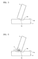
- the steel plate deck 1 is produced by welding the closed section ribs 3 to the deck plate. Firstly, as shown in FIG. 5 , the root face 3b of the closed section rib 3 is made to contact the surface 2a of the deck plate 2. In this state, as shown in FIG.6 , welding is performed from the side of the groove 3c.
- a general welding method such as submerged arc welding, gas-shielded metal arc welding or the like may be employed.
- the electric power supply for the welding may have a general characteristic such as DC constant voltage, DC drooping (constant current) characteristic, AC drooping characteristic, or the like.
- Molten slag 5 and blowholes are generated during the welding. However, intrusion of the molten slag 5 and blowholes stops short of the root face 3b. Since the welding is performed from the groove 3c to a portion of the root face 3b, molten slag 5 and blowholes are eliminated by the molten metal during the process of the welding. During the welding, heat conduction occurs actively in the contact portion between the closed section rib 3 and the deck plate 2. Therefore, even when the heat input is increased, melting of the closed section ribs 3 caused by the welding heat is effectively inhibited.
- the root face 3b is provided at the root portion of the rib edge 3a of the closed section ribs 3, and the welding of the closed section ribs 3 to the deck plate 2 is performed in the state such that the root face 3b of the closed section ribs 3 is made to contact the surface 2a of the deck plate 2. Therefore, intrusion of the molten slag 5 and blowholes stops in short of the root face 3b, and the molten slag 5 and blowholes are eliminated by the molten metal. As a result, without increasing the amount of penetration, generation of molten slag 5 and blowholes is prevented, and a stable amount of penetration is ensured.
- Test samples (SM490A and 1000 mm in length) were produced to have a various root faces as shown in Table 1, where the plate thickness t of a rib was in the range of 6 mm to 18 mm, and a setting angle ⁇ was in the range of 65° to 85°. Each sample was subjected to evaluation using submerged arc welding and gas shielded metal arc welding.
- the submerged arc welding was performed by using a solid wire (JIS Z3351 YS-S6) and fused flux (JIS Z3352 FS-FP1).
- the gas-shielded metal arc welding was performed using a flux cored wire (JIS Z3313 YFW-C50DM).
- JIS Z3313 YFW-C50DM a flux cored wire
- the results of evaluation tests of the welding are summarized in Table 3.
- the amount D of penetration was determined as an averaged value obtained from three test pieces obtained from each sample after the welding for macroscopic observation. Absence or presence of slag inclusion was examined based on the observation of the above-described test pieces of macroscopic sections and observation of ruptured face s formed by cleaving the test pieces after cutting a V-notch in a surface of a bead of a weld zone of each of the test pieces. The absence or presence of blowholes was also examined based on the observation of the rupture faces.
- Example 1 to 10 exhibited satisfactory penetration where slag inclusion or generation of blowholes was not observed (negative) and burn through towards the back surface of the rib did not occur.
- Excluding Examples 3, 6, and 9, Examples according to the present invention demonstrated that a complete penetration was effectively prevented (penetration ratio was no greater than 95%) while ensuring deep penetration of a penetration ratio of not larger than 70%.
- Comparative Examples 11 to 15 root faces were not provided to the rib edges.
- Comparative Examples 11 and 13 burn through occurred by penetration reaching to the back surface of the plate of the rib.
- molten metal did not reach the molten slag that intruded into the root portions of the rib edges and slag inclusion occurred. Comparative Examples 12, 14, and 15 also showed an occurrence of blowholes.
- FIG. 9 shows a photograph of a macroscopic test piece of Example 4 for sectional observation.
- FIG. 10 shows a photograph of a ruptured face of the test piece.
- FIG. 7 shows a photograph of a macroscopic test piece of Comparative Example 14 for sectional observation.
- FIG. 8 shows a photograph of a ruptured face of the test piece.
- Example 4 according to the present invention, slag inclusion was not observed.
- Comparative Example 14 it was observed that slag inclusion 10 occurred in the time of forming the weld zone 40 by welding the deck plate 20 and the rib 30.
- molten slag 5 and blowholes could be eliminated during the welding. Therefore, generation of residual molten slag and blowholes was inhibited and a stable amount of penetration could be achieved.
- the present invention it is possible to inhibit generation of residual molten slag and blowholes during production of a steel plate deck by welding a closed section rib and a deck plate. As a result, it is possible to achieve a steel plate deck that does not include residual molten slag and blow holes and has high static strength and high elastic strength.
Landscapes
- Engineering & Computer Science (AREA)
- Mechanical Engineering (AREA)
- Physics & Mathematics (AREA)
- Plasma & Fusion (AREA)
- Butt Welding And Welding Of Specific Article (AREA)
- Bridges Or Land Bridges (AREA)
- Joining Of Building Structures In Genera (AREA)
Abstract
Description
- The present invention relates to a method of welding and a steel plate deck.
- A steel plate deck is known as a flooring material used for buildings such as bridges. A steel plate deck is constituted of a deck plate (steel plate) and a plurality stiffeners (ribs) arranged on the deck plate, and the deck plate and the ribs are integrated with each other by longitudinal welding (Japanese Unexamined Patent Application, First Publication, No.
2003-183769 H08-281476 2003-080396 - Full-penetration welding using a backing metal, gas-shielded metal arc welding, and submerged arc welding are generally known methods of welding. Particularly, full-penetration welding is known as an effective method in that a high amount of penetration is stably ensured.
- On the other hand, in the case of welding of a deck plate and a closed section rib, it is difficult to perform full-penetration welding since the structure of the closed-section ribs makes it difficult to use a backing metal. Therefore, gas-shielded metal arc welding, submerged arc welding or the like have conventionally been used in the welding of the deck plate and the closed-section rib. In such methods, welding is performed while edges of the closed section ribs are made to contact the deck plate. A portion of an edge of each rib, which is made to contact the deck plate, is called a root portion.
- In general, the edge of the rib has a root portion which is cut to have an orthogonal or nearly orthogonal angle. Therefore, when the edge of the rib is made to contact the deck plate, only the root portion is in contact with the deck plate, forming a clearance (groove) corresponding to a setting angle between the deck plate and the edge of the rib.
- When the welding is performed in that state, there is a case in which molten slag generated during the welding intrudes into the groove. In addition, blowholes are easily formed by the gas generated during the welding. When the molten slag and the blowholes generated during the welding intrude to an extent deeper than the target amount of penetration, the molten slag and blowholes remain in those states. The residual slag and blowholes cause slag inclusion and/or insufficient amount of penetration.
- Japanese Unexamined Patent Application, First Publication No.
H08-281476 2003-80396 - In a technique proposed as a solution for these problems, generation of the above-described defects is avoided by increasing the amount of penetration such that the melting proceeds to a position deeper than the position of intrusion of the molten slag and the blowholes. However, the increased amount of penetration sometimes results in excessive melting that reaches the back surface (inner surface of the U-shaped member) of the closed section ribs, thereby making it difficult to control a stable amount of penetration, and causing unstable forms of beads.
- An object of the present invention is to provide a welding method which enables a stable amount of penetration while inhibiting generation of residual molten slag. Another object of the present invention is to provide a steel plate deck.
- A welding method according to the present invention is a method of welding a deck plate (steel plate) and a closed section rib that constitute a steel plate deck, including shaping a root portion of the closed section rib to have a flat surface in parallel with a surface of the deck plate, and welding the deck plate and the closed section rib while making the flat surface of the closed section rib to contact the surface of the deck plate.
- In the above-described method of welding, the root portion at the rib edge of the closed section rib has a flat surface, and the deck plate and the rib are welded in a state such that the flat surface of the closed section rib is made to contact the surface of the deck plate. Therefore, intrusion of the molten slag and blowholes is limited to the position bordered by the contact portion, and the molten slag and the blowholes are eliminated by the molten metal. As a result, it is possible to prevent the generation of residual molten slag and blowholes without increasing the amount of penetration, and to ensure a stable amount of penetration. In addition, since the amount of penetration can be controlled by controlling the dimension of the flat surface, it is possible to suppress any change in the amount of penetration caused by a change in the welding conditions. By this, a stable amount of penetration can be achieved. Since active heat conduction occurs at the contact portion between the closed section rib and the deck plate during welding, it is possible to suppress the melting of the closed section rib caused by the welding heat even when the welding temperature is increased. Therefore, there is an advantage in that the range of welding conditions can be enlarged.
- In the above-described welding method, it is preferable that the dimension of the flat surface along the surface direction of the deck plate be 5 to 50% of the rib thickness (thickness of a plate forming the rib) of the closed section rib.
By controlling the dimension of the flat surface along the surface direction of the deck plate (in other words, the width of the flat surface in parallel to the surface direction of the deck plate) to be 5 to 50 % of the rib thickness of the closed section rib, it is possible to set an appropriate value of the dimension of the flat surface in accordance with the rib thickness of the closed section rib. Where the dimension of the flat surface is smaller than 5% of the rib thickness, there is a possibility of melting occurring on the back surface side of the closed section rib. By controlling the dimension of the flat surface to be not smaller than 5%, it is possible to prevent the melting occurring on the back surface side of the closed section rib. Where the dimension of the flat surface is larger than 50% of the rib thickness, there is a possibility that the groove portion formed between the rib edge and the deck plate has a small size, thereby reducing the amount of penetration. By controlling the dimension of the flat surface to be not greater than 50% of the rib thickness, it is possible to ensure a high amount of penetration. - In the above-described welding method, it is preferable that the welding be performed such that the penetration of the welding covers a portion of the flat surface.
By performing the welding such that the penetration of the welding covers a portion of the flat surface, the groove portion formed between the rib edge and the deck plate is completely covered by the penetration of the welding. As a result, it is possible to eliminate molten slag and blowholes generated in the groove portion. - A steel plate deck according to the present invention comprises: a deck plate; a closed section rib that is provided on a surface of the deck plate and has a root portion at the edge of the rib, where the root portion has a flat surface that is in parallel with the surface of the deck plate and made to contact the surface of the deck plate; and a weld zone that fixes the closed section ribs to the deck plate.
- According to the present invention, the closed section rib provided on the surface of the deck plate via the weld zone has a flat surface at the root portion at the rib edge, and the flat surface is made to contact the surface of the deck plate. Therefore, it is possible to provide a steel plate deck in which molten slag and blowholes hardly occur. By this constitution, it is possible to provide a steel plate deck having high static strength and high elastic strength.
- In the above-described steel plate deck, it is preferable that the dimension of the flat surface along the surface direction of the deck plate be 5 to 50% of the rib thickness of the closed section rib.
According to the present invention, by controlling the dimension of the flat surface along the surface direction of the deck plate to be 5 to 50% of the rib thickness of the closed section rib, it is possible to set an appropriate value of the dimension of the flat surface in accordance with the rib thickness of the closed section rib. By controlling the dimension of the flat surface to be not smaller than 5%, it is possible to avoid melting occurring on the back surface side of the closed section rib. By controlling the dimensions of the flat surface to be not greater than 50% of the rib thickness, it is possible to ensure a high amount of penetration. - In the above-described steel plate deck, it is preferable that the weld zone covers a portion of the flat surface. Where the weld zone covers a portion of the flat surface, the groove formed between the rib edge and the deck plate is completely covered by the weld zone. By this constitution, it is possible to provide a steel plate deck which is free of molten slag and blowholes in the groove portion.
- According to the present invention, the root portion at the rib edge of the closed section rib has a flat surface, and the deck plate and the closed section rib is welded in a state such that the flat surface of the closed section rib is made to contact the surface of the deck plate. Therefore, intrusion of molten slag and blowholes stops short of the contact portion, and the molten slag and blowholes are eliminated by the molten metal. By this constitution, it is possible to prevent the generation of residual slag and blowholes, ensuring a stable amount of penetration. In addition, since the amount of penetration can be controlled by controlling the dimension of the flat surface, it is possible to suppress any change in the amount of penetration caused by changes in the welding conditions. Therefore, it is possible to achieve a stable amount of penetration. Moreover, since heat conduction occurs actively at the contact portion between the closed section rib and the deck plate during welding, it is possible to suppress the melting of the closed section rib by the weld heat even when the welding is performed under high temperature conditions. Therefore, there is an advantage of providing a wide range of welding conditions.
-
-
FIG. 1 is a drawing showing a steel plate deck according to an embodiment of the present invention. -
FIG. 2 is a drawing showing a constitution of a steel plate deck according to the present invention. -
FIG. 3 is a drawing showing a constitution of a joint portion of a steel plate deck according to the present embodiment. -
FIG. 4 is a drawing showing a constitution of a closed section rib according to the present embodiment. -
FIG. 5 is a drawing showing a welding process according to the present invention. -
FIG. 6 is a drawing showing a welding process according to the present invention. -
FIG. 7 is a photograph showing a joint portion of a steel plate deck according to the prior art. -
FIG. 8 is a photograph showing a ruptured face according to the prior art. -
FIG. 9 is a photograph showing a contact portion of the steel plate deck according to the present invention. -
FIG. 10 is a drawing showing a ruptured face according to an example of the present invention. - An embodiment of the present invention is explained below with reference to the drawings.
FIG. 1 is a strabismus view showing a constitution of a steel plate deck 1 according to the present invention. As shown in the figure, the steel plate deck 1 is mainly constituted of adeck plate 2 andclosed section ribs 3. The steel plate deck 1 is used as a floor member of a building structure, for example, a bridge. - The
deck plate 2 is a rectangular plate member having a predetermined thickness and is made of steel.
A plurality of theclosed section ribs 3 are provided on asurface 2a of thedeck plate 2. Eachclosed section rib 3 is a shaped steel having a U-shaped section formed by bending a flat steel plate having a predetermined thickness. Each of theclosed section ribs 3 elongates along a side of thedeck plate 2, and in the direction perpendicular to the elongation direction, a plurality of theclosed section ribs 3 are arranged with a predetermined pitch in between. Theclosed section ribs 3 are joined to thedeck plate 2 by welding. -
FIG. 2 is a strabismus view showing the constitution of theclosed section rib 3 on thedeck plate 2.
As shown in the figure,weld zones 4 are provided at the joint portions between thedeck plate 2 and theclosed section ribs 3. Each of theweld zones 4 is provided so as to cover the outside region of the U-shapedclosed section rib 3 along arib edge 3a. Theweld zones 4 may be welded by using general welding consumables such as solid wire, fused flux, flux cored wire or the like. -
FIG. 3 is a drawing showing a constitution of a section of the steel plate deck 1 sectioned along A-A inFIG. 2 . While the figure only shows onerib edge 3a of theclosed section ribs 3, another3a rib edge 3a has a similar constitution.
As shown in the figure, eachrib edge 3a of theclosed section rib 3 is connected to thesurface 2a of thedeck plate 2 forming a predetermined inclination angle (setting angle) θ. Preferably, the setting angle θ is set to be in the range of 65° to 85°. A flat surface (root face) 3b is provided at the root portion of therib edge 3a. Theroot face 3b contacts thesurface 2a of thedeck plate 2. A portion of therib edge 3a from the outer end to the end of theroot face 3b does not contact thedeck plate 2, forming a clearance (groove) 3c between therib edge 3a and thedeck plate 2. Theweld zone 4 is provided so as to cover the entire portion of thegroove 3c and a portion of theroot face 3b. -
FIG. 4 is a drawing showing a constitution of a portion (rib edge 3a) of theclosed section rib 3.
As shown in the figure, theclosed section rib 3 is constituted so as to have a plate thickness t of about 6 to 18 mm. A dimension RF of the root face is preferably set in the range of 0.05 to 0.5 times the plate thickness t of the rib (RF=0.05t to 0.5t), more preferably, in the range of 0.05 to 0.4 times the plate thickness t of the rib (RF=0.05t to 0.4t). - A dimension s of the
groove 3c along the plate thickness of the rib is determined in accordance with the plate thickness t of therib 3 and a target value of an amount of penetration. For example, where the plate thickness t of therib 3 is about 12 mm, the dimension s of thegroove 3c along the plate thickness direction of therib 3 is about 7.5 mm, and the target amount D of penetration is set to be about 75% to 80% of the plate thickness t of therib 3, a portion of theroot face 3b where aweld zone 4 is formed has a dimension 1 in the range of about 1 mm to 1.5 mm. To ensure a stable amount D of penetration, the amount D of penetration may be controlled by controlling the dimension of theroot face 3b. - Next a production method of a steel plate deck 1 having the above-described constitution is explained. The steel plate deck 1 is produced by welding the
closed section ribs 3 to the deck plate.
Firstly, as shown inFIG. 5 , theroot face 3b of theclosed section rib 3 is made to contact thesurface 2a of thedeck plate 2. In this state, as shown inFIG.6 , welding is performed from the side of thegroove 3c. As the method of welding, a general welding method such as submerged arc welding, gas-shielded metal arc welding or the like may be employed. The electric power supply for the welding may have a general characteristic such as DC constant voltage, DC drooping (constant current) characteristic, AC drooping characteristic, or the like. -
Molten slag 5 and blowholes are generated during the welding. However, intrusion of themolten slag 5 and blowholes stops short of theroot face 3b. Since the welding is performed from thegroove 3c to a portion of theroot face 3b,molten slag 5 and blowholes are eliminated by the molten metal during the process of the welding. During the welding, heat conduction occurs actively in the contact portion between theclosed section rib 3 and thedeck plate 2. Therefore, even when the heat input is increased, melting of theclosed section ribs 3 caused by the welding heat is effectively inhibited. - Thus, according to the present embodiment, the
root face 3b is provided at the root portion of therib edge 3a of theclosed section ribs 3, and the welding of theclosed section ribs 3 to thedeck plate 2 is performed in the state such that theroot face 3b of theclosed section ribs 3 is made to contact thesurface 2a of thedeck plate 2. Therefore, intrusion of themolten slag 5 and blowholes stops in short of theroot face 3b, and themolten slag 5 and blowholes are eliminated by the molten metal. As a result, without increasing the amount of penetration, generation ofmolten slag 5 and blowholes is prevented, and a stable amount of penetration is ensured. - Test samples (SM490A and 1000 mm in length) were produced to have a various root faces as shown in Table 1, where the plate thickness t of a rib was in the range of 6 mm to 18 mm, and a setting angle θ was in the range of 65° to 85°. Each sample was subjected to evaluation using submerged arc welding and gas shielded metal arc welding.
-
Table 1. Symbol Rib plate thickness t (mm) Setting angle θ(degree) Root face RF(mm) Root face/rib plate thickness RF/t (%) Method of welding Examples of the present invention 1 6 85 0.5 8 Submerged Arc welding 2 6 65 3.0 50 3 12 65 0.5 4 4 12 75 2.0 17 5 12 65 5.5 46 6 12 75 6.5 54 7 18 85 3.5 19 8 18 65 6.5 36 9 18 75 10 56 10 12 75 2.5 21 Gas-shielded metal arc welding Comparative Example 11 6 75 0 0 Submerged Arc welding 12 6 75 0 0 13 12 65 0 0 14 12 75 0 0 15 18 85 0 0 - The submerged arc welding was performed by using a solid wire (JIS Z3351 YS-S6) and fused flux (JIS Z3352 FS-FP1). The gas-shielded metal arc welding was performed using a flux cored wire (JIS Z3313 YFW-C50DM). For each of the welding method and plate thickness of the rib, welding was performed using conditions shown in Table 2.
-
Table 2 Welding method Rib plate Thickness t (mm) Power supply characteristic Wire diameter (mmΦ) Welding Current (A) Arc voltage (V) Welding Speed (cm/min) Submerged arc welding 6 AC 2.0 450 32 60 12 DC constant current 3.2 650 32 55 18 DC constant current 4.0 800 32 45 Gas-shielded metal arc welding 12 DC constant current 1.4 400 36 40 * torch angle: 45°, wire extension: 25 mm,
* Shielding gas: CO2-25 l/min - The results of evaluation tests of the welding are summarized in Table 3. The amount D of penetration was determined as an averaged value obtained from three test pieces obtained from each sample after the welding for macroscopic observation. Absence or presence of slag inclusion was examined based on the observation of the above-described test pieces of macroscopic sections and observation of ruptured face s formed by cleaving the test pieces after cutting a V-notch in a surface of a bead of a weld zone of each of the test pieces. The absence or presence of blowholes was also examined based on the observation of the rupture faces.
-
Table 3 Symbol Depth of penetration (mm) Penetration rate D/t (%) Slag inclusion Generation of blowholes Burn through towards the back surface of the rib plate Examples of the present invention 1 5.5 92 negative negative negative 2 4.5 75 negative negative negative 3 11.6 97 negative negative negative 4 10.5 88 negative negative negative 5 8.6 72 negative negative negative 6 8.0 67 negative negative negative 7 14.6 81 negative negative negative 8 13.7 76 negative negative negative 9 11.6 64 negative negative negative 10 9.8 82 negative negative negative Comparative Example 11 >6.0 >100 negative negative positive (seven/m) 12 5.4 90 positive positive negative 13 11.8 98 positive negative positive (2/m) 14 10.8 90 positive positive negative 15 14.7 82 positive positive negative - Each of the Examples 1 to 10 according to the present invention exhibited satisfactory penetration where slag inclusion or generation of blowholes was not observed (negative) and burn through towards the back surface of the rib did not occur. Excluding Examples 3, 6, and 9, Examples according to the present invention demonstrated that a complete penetration was effectively prevented (penetration ratio was no greater than 95%) while ensuring deep penetration of a penetration ratio of not larger than 70%. In Comparative Examples 11 to 15, root faces were not provided to the rib edges. In Comparative Examples 11 and 13, burn through occurred by penetration reaching to the back surface of the plate of the rib. In Comparative Examples 12, 14, and 15, molten metal did not reach the molten slag that intruded into the root portions of the rib edges and slag inclusion occurred. Comparative Examples 12, 14, and 15 also showed an occurrence of blowholes.
- As an example of the present invention,
FIG. 9 shows a photograph of a macroscopic test piece of Example 4 for sectional observation.FIG. 10 shows a photograph of a ruptured face of the test piece.
As a comparative example,FIG. 7 shows a photograph of a macroscopic test piece of Comparative Example 14 for sectional observation.FIG. 8 shows a photograph of a ruptured face of the test piece.
In Example 4, according to the present invention, slag inclusion was not observed. On the other hand, in Comparative Example 14, it was observed thatslag inclusion 10 occurred in the time of forming theweld zone 40 by welding thedeck plate 20 and therib 30. - As explained above, according to the present invention,
molten slag 5 and blowholes could be eliminated during the welding. Therefore, generation of residual molten slag and blowholes was inhibited and a stable amount of penetration could be achieved. - According to the present invention, it is possible to inhibit generation of residual molten slag and blowholes during production of a steel plate deck by welding a closed section rib and a deck plate. As a result, it is possible to achieve a steel plate deck that does not include residual molten slag and blow holes and has high static strength and high elastic strength.
Claims (6)
- A method of welding a deck plate and a closed section rib both constituting a steel plate deck, comprising:working a root portion of the closed section rib to have a flat surface in parallel with a surface of the deck plate;welding the deck plate and the closed section rib while making the flat surface of the closed section rib to be in contact with a surface of the deck plate.
- A method of welding according to claim 1, wherein a dimension of the flat surface along a surface direction of the deck plate is 5% to 50% of a rib thickness of the closed section rib.
- A method of welding according to claim 1 or 2, wherein the welding is performed such that a penetration formed by the welding covers a portion of the flat surface.
- A steel plate deck comprising:a deck plate;a closed section rib that is provided on a surface of the deck plate and has a root portion at the edge of the rib, where the root portion has a flat surface that is in parallel with the surface of the deck plate and made to be in contact with the surface of the deck plate; anda weld zone that fixes the closed section rib to the deck plate.
- A steel plate deck according to claim 4, wherein a dimension of the flat surface along a surface direction of the deck plate is 5% to 50% of a rib thickness of the closed section rib.
- A steel plate deck according to claim 4 or 5, wherein the weld zone covers a portion of the flat surface.
Applications Claiming Priority (2)
| Application Number | Priority Date | Filing Date | Title |
|---|---|---|---|
| JP2007186047A JP2009022963A (en) | 2007-07-17 | 2007-07-17 | Welding method and steel plate floor |
| PCT/JP2008/056558 WO2009011156A1 (en) | 2007-07-17 | 2008-04-02 | Welding method and steel plate floor |
Publications (2)
| Publication Number | Publication Date |
|---|---|
| EP2179813A1 true EP2179813A1 (en) | 2010-04-28 |
| EP2179813A4 EP2179813A4 (en) | 2014-01-22 |
Family
ID=40259499
Family Applications (1)
| Application Number | Title | Priority Date | Filing Date |
|---|---|---|---|
| EP08739669.3A Withdrawn EP2179813A4 (en) | 2007-07-17 | 2008-04-02 | Welding method and steel plate floor |
Country Status (4)
| Country | Link |
|---|---|
| US (1) | US7921562B2 (en) |
| EP (1) | EP2179813A4 (en) |
| JP (1) | JP2009022963A (en) |
| WO (1) | WO2009011156A1 (en) |
Families Citing this family (9)
| Publication number | Priority date | Publication date | Assignee | Title |
|---|---|---|---|---|
| JP4975062B2 (en) * | 2009-05-07 | 2012-07-11 | Jfeスチール株式会社 | Steel pipe stiffening brace material and manufacturing method thereof |
| US8943691B2 (en) * | 2009-11-03 | 2015-02-03 | Ashley Dean Olsson | Furcated composite post |
| JP4688234B1 (en) * | 2010-03-16 | 2011-05-25 | 株式会社 構造材料研究会 | Rectangular metal plate square tube reinforcement structure |
| WO2012060020A1 (en) * | 2010-11-05 | 2012-05-10 | Jfeスチール株式会社 | Steel pipe stiffening brace and production method therefor |
| JP5154672B2 (en) * | 2011-05-24 | 2013-02-27 | Jfeスチール株式会社 | Automobile frame parts |
| US8726610B2 (en) * | 2012-08-29 | 2014-05-20 | General Electric Company | Crack-resistant member, a method of preventing crack propagation, and a method of assembling a tower |
| EP3480135A1 (en) * | 2017-11-06 | 2019-05-08 | Kärcher Futuretech GmbH | Mobile container building for military, humanitarian and/or expedition-like use |
| JP7052562B2 (en) * | 2018-05-25 | 2022-04-12 | 日本製鉄株式会社 | Steel deck and steel deck manufacturing method |
| US11933046B1 (en) * | 2022-07-14 | 2024-03-19 | Anthony Attalla | Stiff wall panel assembly for a building structure and associated method(s) |
Citations (2)
| Publication number | Priority date | Publication date | Assignee | Title |
|---|---|---|---|---|
| JPS597482A (en) * | 1982-07-05 | 1984-01-14 | Hitachi Zosen Corp | One side fillet welding method |
| JP2006224137A (en) * | 2005-02-17 | 2006-08-31 | Ishikawajima Harima Heavy Ind Co Ltd | Reinforced plate, and reinforced plate manufacturing method |
Family Cites Families (23)
| Publication number | Priority date | Publication date | Assignee | Title |
|---|---|---|---|---|
| US1842612A (en) * | 1927-11-15 | 1932-01-26 | Truscon Steel Co | Skeleton beam |
| US2662272A (en) * | 1949-02-15 | 1953-12-15 | Macomber Inc | Manufacture of fabricated joists |
| US2624430A (en) * | 1949-06-18 | 1953-01-06 | Macomber Inc | Fabricated joist |
| BE639419A (en) * | 1962-11-09 | |||
| US3300854A (en) * | 1964-05-14 | 1967-01-31 | Mcdonnell Aircraft | Method of making refractory metal structures with an oxidation resistant coating |
| US3454396A (en) * | 1964-07-09 | 1969-07-08 | Minnesota Mining & Mfg | Fuel elements |
| US3882654A (en) * | 1973-04-09 | 1975-05-13 | Caterpillar Tractor Co | Stress-Relieved Weldment for Box Sections |
| US3961738A (en) * | 1973-04-11 | 1976-06-08 | C-O, Inc. | Apparatus for making truss members |
| US4241146A (en) * | 1978-11-20 | 1980-12-23 | Eugene W. Sivachenko | Corrugated plate having variable material thickness and method for making same |
| GB8523933D0 (en) * | 1985-09-27 | 1985-10-30 | British Shipbuilders Eng | Large sandwich structures |
| US4966082A (en) * | 1987-10-21 | 1990-10-30 | Hitachi, Ltd. | Construction and a manufacturing method of underframe for a rolling stock |
| US5635306A (en) * | 1992-03-30 | 1997-06-03 | Nippon Steel Corporation | Honeycomb panel and process for producing same |
| JP2539142B2 (en) | 1992-08-25 | 1996-10-02 | 株式会社巴コーポレーション | Manufacturing method of large angle material for hot dip galvanizing |
| JP2832509B2 (en) * | 1994-01-20 | 1998-12-09 | 関東冶金工業株式会社 | Metal alloy material joining method |
| US5551135A (en) * | 1994-05-25 | 1996-09-03 | Powers, Iii; John | Method of fabricating a metal purlin and method of fabricating a building therewith |
| JP3442187B2 (en) | 1995-04-10 | 2003-09-02 | 日鐵住金溶接工業株式会社 | Flux-cored wire for gas shielded arc welding |
| JP3499081B2 (en) | 1996-05-29 | 2004-02-23 | 株式会社神戸製鋼所 | Joint welding method and material to be welded |
| JP2001248114A (en) | 2000-03-07 | 2001-09-14 | Nkk Corp | Reinforcing method for steel floor board and steel floor board structure |
| WO2003018853A2 (en) * | 2001-08-24 | 2003-03-06 | University Of Virginia Patent Foundation | Reversible shape memory multifunctional structural designs and method of using and making the same |
| JP3815600B2 (en) | 2001-09-07 | 2006-08-30 | 日鐵住金溶接工業株式会社 | One side horizontal fillet gas shielded arc welding method |
| JP2003183769A (en) | 2001-12-11 | 2003-07-03 | Nippon Steel Corp | Long-life steel structure |
| NL1020262C2 (en) | 2002-03-27 | 2003-06-11 | Bouwe Guustaaf Dirk De Wilde | Modular electronic device. |
| JP2008272826A (en) * | 2007-02-15 | 2008-11-13 | Ihi Corp | Stiffened plate and process for producing the same |
-
2007
- 2007-07-17 JP JP2007186047A patent/JP2009022963A/en active Pending
-
2008
- 2008-04-02 WO PCT/JP2008/056558 patent/WO2009011156A1/en active Application Filing
- 2008-04-02 EP EP08739669.3A patent/EP2179813A4/en not_active Withdrawn
- 2008-06-27 US US12/147,712 patent/US7921562B2/en active Active
Patent Citations (2)
| Publication number | Priority date | Publication date | Assignee | Title |
|---|---|---|---|---|
| JPS597482A (en) * | 1982-07-05 | 1984-01-14 | Hitachi Zosen Corp | One side fillet welding method |
| JP2006224137A (en) * | 2005-02-17 | 2006-08-31 | Ishikawajima Harima Heavy Ind Co Ltd | Reinforced plate, and reinforced plate manufacturing method |
Non-Patent Citations (1)
| Title |
|---|
| See also references of WO2009011156A1 * |
Also Published As
| Publication number | Publication date |
|---|---|
| EP2179813A4 (en) | 2014-01-22 |
| US7921562B2 (en) | 2011-04-12 |
| US20090019809A1 (en) | 2009-01-22 |
| WO2009011156A1 (en) | 2009-01-22 |
| JP2009022963A (en) | 2009-02-05 |
Similar Documents
| Publication | Publication Date | Title |
|---|---|---|
| EP2179813A1 (en) | Welding method and steel plate floor | |
| JP6119940B1 (en) | Vertical narrow groove gas shielded arc welding method | |
| US7896979B2 (en) | Activating flux for welding stainless steels | |
| KR20160144494A (en) | Vertical narrow gap gas shielded arc welding method | |
| CN111886104A (en) | Gas shielded arc welding method for steel plate | |
| EP3541558B1 (en) | Method of cleaning a workpiece after a thermal joining process with cathodic cleaning ; cleaning device | |
| JP6439882B2 (en) | Vertical narrow groove gas shielded arc welding method | |
| CN110177643B (en) | Single-sided submerged arc welding method and single-sided submerged arc welding device | |
| JP2011189363A (en) | Horizontal gas shield arc welding method | |
| JP6119948B1 (en) | Vertical narrow groove gas shielded arc welding method | |
| KR102032106B1 (en) | Vertical direction narrow gas shielded arc welding method | |
| JP2009255172A (en) | Method for manufacturing t-type joint | |
| WO2019151162A1 (en) | One-side submerged arc welding method and one-side submerged arc welding device | |
| KR102424484B1 (en) | Tandem gas shield arc welding method and welding device | |
| JP6949745B2 (en) | Single-sided submerged arc welding method and single-sided submerged arc welding equipment | |
| JP3706892B2 (en) | 4-electrode single-sided submerged arc welding method | |
| JP7136709B2 (en) | Single-sided submerged arc welding method and single-sided submerged arc welding apparatus | |
| JP6119949B1 (en) | Vertical narrow groove gas shielded arc welding method | |
| KR102046957B1 (en) | High Efficient Welded Joint Having Excellent Brittle Crack Propagation Stopping Performance and Method for Manufacturing the Same | |
| JPH09155550A (en) | End crack preventing method in high speed one side submerged arc welding | |
| JP6101724B2 (en) | Welding method of galvanized steel sheet | |
| KR960001532Y1 (en) | Grease spreading device for flash butt welding | |
| JP2006334654A (en) | Electro-slag welding method | |
| JP2007175732A (en) | Consumable nozzle for electro-slag welding |
Legal Events
| Date | Code | Title | Description |
|---|---|---|---|
| PUAI | Public reference made under article 153(3) epc to a published international application that has entered the european phase |
Free format text: ORIGINAL CODE: 0009012 |
|
| 17P | Request for examination filed |
Effective date: 20100215 |
|
| AK | Designated contracting states |
Kind code of ref document: A1 Designated state(s): AT BE BG CH CY CZ DE DK EE ES FI FR GB GR HR HU IE IS IT LI LT LU LV MC MT NL NO PL PT RO SE SI SK TR |
|
| AX | Request for extension of the european patent |
Extension state: AL BA MK RS |
|
| RIN1 | Information on inventor provided before grant (corrected) |
Inventor name: OTA, MAKOTO Inventor name: NISHIYAMA, SHIGEKI Inventor name: MATSUOKA, TSUTOMU Inventor name: FUJIWARA, MASASHI Inventor name: KIJI, NOBORU |
|
| RAP1 | Party data changed (applicant data changed or rights of an application transferred) |
Owner name: KABUSHIKI KAISHA KOBE SEIKO SHO Owner name: IHI INFRASTRUCTURE SYSTEMS CO., LTD. |
|
| DAX | Request for extension of the european patent (deleted) | ||
| A4 | Supplementary search report drawn up and despatched |
Effective date: 20131220 |
|
| RIC1 | Information provided on ipc code assigned before grant |
Ipc: B23K 9/02 20060101ALI20131216BHEP Ipc: B23K 103/04 20060101ALI20131216BHEP Ipc: B23K 9/00 20060101AFI20131216BHEP Ipc: E01D 19/12 20060101ALI20131216BHEP Ipc: B23K 9/18 20060101ALI20131216BHEP Ipc: B23K 9/025 20060101ALI20131216BHEP |
|
| STAA | Information on the status of an ep patent application or granted ep patent |
Free format text: STATUS: THE APPLICATION HAS BEEN WITHDRAWN |
|
| 18W | Application withdrawn |
Effective date: 20140424 |