EP2179130B1 - Method and apparatus for monitoring offshore contamination - Google Patents
Method and apparatus for monitoring offshore contamination Download PDFInfo
- Publication number
- EP2179130B1 EP2179130B1 EP08776053.4A EP08776053A EP2179130B1 EP 2179130 B1 EP2179130 B1 EP 2179130B1 EP 08776053 A EP08776053 A EP 08776053A EP 2179130 B1 EP2179130 B1 EP 2179130B1
- Authority
- EP
- European Patent Office
- Prior art keywords
- seawater
- sensor
- facility
- contamination
- data
- Prior art date
- Legal status (The legal status is an assumption and is not a legal conclusion. Google has not performed a legal analysis and makes no representation as to the accuracy of the status listed.)
- Not-in-force
Links
Images
Classifications
-
- E—FIXED CONSTRUCTIONS
- E21—EARTH OR ROCK DRILLING; MINING
- E21B—EARTH OR ROCK DRILLING; OBTAINING OIL, GAS, WATER, SOLUBLE OR MELTABLE MATERIALS OR A SLURRY OF MINERALS FROM WELLS
- E21B43/00—Methods or apparatus for obtaining oil, gas, water, soluble or meltable materials or a slurry of minerals from wells
- E21B43/01—Methods or apparatus for obtaining oil, gas, water, soluble or meltable materials or a slurry of minerals from wells specially adapted for obtaining from underwater installations
- E21B43/0122—Collecting oil or the like from a submerged leakage
-
- G—PHYSICS
- G01—MEASURING; TESTING
- G01N—INVESTIGATING OR ANALYSING MATERIALS BY DETERMINING THEIR CHEMICAL OR PHYSICAL PROPERTIES
- G01N33/00—Investigating or analysing materials by specific methods not covered by groups G01N1/00 - G01N31/00
- G01N33/18—Water
- G01N33/1886—Water using probes, e.g. submersible probes, buoys
-
- G—PHYSICS
- G01—MEASURING; TESTING
- G01N—INVESTIGATING OR ANALYSING MATERIALS BY DETERMINING THEIR CHEMICAL OR PHYSICAL PROPERTIES
- G01N33/00—Investigating or analysing materials by specific methods not covered by groups G01N1/00 - G01N31/00
- G01N33/18—Water
- G01N33/1826—Organic contamination in water
- G01N33/1833—Oil in water
-
- Y—GENERAL TAGGING OF NEW TECHNOLOGICAL DEVELOPMENTS; GENERAL TAGGING OF CROSS-SECTIONAL TECHNOLOGIES SPANNING OVER SEVERAL SECTIONS OF THE IPC; TECHNICAL SUBJECTS COVERED BY FORMER USPC CROSS-REFERENCE ART COLLECTIONS [XRACs] AND DIGESTS
- Y02—TECHNOLOGIES OR APPLICATIONS FOR MITIGATION OR ADAPTATION AGAINST CLIMATE CHANGE
- Y02A—TECHNOLOGIES FOR ADAPTATION TO CLIMATE CHANGE
- Y02A20/00—Water conservation; Efficient water supply; Efficient water use
- Y02A20/20—Controlling water pollution; Waste water treatment
Definitions
- the present invention relates to a method of monitoring the water surrounding an offshore hydrocarbon well in order to detect contamination deriving from that well, and additionally to apparatus for use in such a method.
- Discharges may be operational or accidental.
- operational discharges include produced water during the production stage and drilling fluids and cuttings during the .drilling stage.
- accidental discharges include hydrocarbons, hydraulic fluids, drilling fluids, cuttings and other chemicals. It is important that such discharges do not cause unacceptable water contamination or other environmental effects and so, when unacceptable discharges occur, it is important for the well operator to take action to reduce or stop contaminant release.
- Such actions may include shutting down drilling operations, stopping hydrocarbon recovery, replacing or repairing equipment, and so on, all of which are expensive. It is therefore important for the well operator to be able to determine not only that contamination has occurred but also the source, nature and severity of the contamination: thus for example if contamination is as a result of leakage from passing shipping, corrective action by the well operator would be ineffective, and if contamination is below threshold values for severity then corrective action may as yet not be required.
- US 3 770 052 A which discloses the features in the preamble of claim 1, relates to the effective monitoring of seawater immediately above offshore hydrocarbon wells in order to detect contamination by the well rather than contamination in the vicinity of the well. There is however still a need for monitoring systems useful in this regard.
- the invention provides a method of detecting seawater contamination from an offshore hydrocarbon well facility comprising a plurality of seabed wellheads connected by hydrocarbon conduits to a seabed pipeline head (e.g. a PLEM) from which a hydrocarbon pipeline leads to a remote hydrocarbon receiving facility, each said wellhead being provided with a protective cover (eg an over-trawlable wellhead protection structure - WHPS) to which is removably attached a sensor unit, each said sensor unit comprising a biological sensor and a data transmitter coupled by a data transmission line to said remote facility, said well facility further comprising a seawater velocity sensor, a seawater conductivity sensor and a temperature sensor also coupled by a data transmission line to said remote facility, wherein data from said data transmission line is analysed to determine indicia of seawater contamination at said well facility and of the seawater flow at said well facility and thereby to provide a signal indicative of seawater contamination above a preselected limit deriving from said well facility.
- a seabed pipeline head e
- the invention provides apparatus for detecting seawater contamination from an offshore hydrocarbon well facility, said apparatus comprising a plurality of removably attached sensor units each attached at the protective cover of a wellhead of said offshore hydrocarbon well facility and each comprising a biological sensor and a data transmitter coupled by a data transmission line to a remote data analysis facility (eg part of a hydrocarbon receiving facility coupled via a hydrocarbon pipeline to a seabed pipeline head (eg a PLEM) at said offshore hydrocarbon well facility), said apparatus further comprising at said offshore hydrocarbon well facility a seawater velocity sensor, a seawater conductivity sensor and a temperature sensor also coupled by a data transmission line to said remote facility, said apparatus optionally and preferably further comprising a computer arranged to analyse data from said data transmission line to determine indicia of seawater contamination at said well facility and of the seawater flow at said well facility and thereby to provide a signal indicative of seawater contamination above a preselected limit deriving from said well facility.
- a remote data analysis facility eg part of
- the well facility also comprise a submerged sediment trap.
- each sensor unit comprises a said seawater velocity sensor, a seawater conductivity sensor and a temperature sensor also coupled by a data transmission line to said remote facility.
- a further such sensor unit is removably attached at the seabed pipeline head module (i.e. the PLEM).
- At least one further sensor unit is placed at a seabed location remote from the well facility, e.g. at a distance of 500 to 1000 m from any wellhead, PLEM or pipeline, especially at a distance of 800 to 2000 m.
- Such "outlier" sensor units may serve to determine a "background” or “control” value for contamination and are desirably placed around the well facility (where at least three outliers are present) or upstream of the well facility in the sense of the normally prevailing seabed current.
- Data transmission from outliers may be via a data transmission line or more preferably by acoustic transmission from a transmitter at the outlier through the seawater to a receiver coupled to the main data transmission line leading from the PLEM, optionally via an intermediately positioned seabed transceiver.
- Acoustic transmissions in the method of the invention are preferably non-continuous, e.g. occurring at time intervals of at least 1 hour and up to 24 hours, and preferably are at frequencies in a wavelength band which has little or no effect on whales, in particular frequencies outside the 17 to 43 kHz band, particularly outside the 1 to 100 kHz band.
- the biosensors in the sensor units are preferably raised relative to the seabed to reduce the influence of normal dirt-raising seabed currents, e.g. at a minimum height of 1 to 10 m, especially 2 to 5 m above the surrounding seabed.
- the bottom of the biosensor for these purposes maybe considered to be the lowest portion of the biosensor in which the species being monitored (the "sentinel" species) is contained.
- the well facility sensor units may optionally and preferably also include sensors selected from the following:
- Passive sampling sensors may be used to detect organic compound contaminants, e.g. aromatic compounds, and generally operate by the use of a semi-permeable membrane which separates the seawater from a solvent in which the organic compounds are soluble.
- the solvent may be recovered and analysed when the sensors are periodically replaced or, more preferably, a spectrometric device is included which can analyse the solvent for organic compound content in situ, e.g. an infra-red spectrophotometer.
- the chlorophyll sensor may be a spectrofluorometer and serves to detect changes in the flora of the body of water surrounding the sensor, e.g. changes in algal content.
- the biosensor may be one or more of the many known biosensors which operate by detecting the effect of changes in the seawater on a selected living species, the sentinel species, usually fish or macroinvertebrates (eg shellfish, crustaceans, sea urchins (eg echinodermata), molluscs and fish, especially filter feeding species, and in particular mussels, clams and scallops), for example changes in respiration, pulse (or heart rhythm), gill movement, population density, growth rate, siphon operation, shell movement (e.g. closure and opening), etc.
- the biosensors will generally include optical recording apparatus, e.g. a camera, and optionally also light sources, e.g. lasers. Such effects are known to be correlatable to changes in chemical and physical environment.
- the sentinel species is preferably one suited to the normal (i.e. non-contaminated) environment at the location at which the biosensor is to be deployed, taking into account parameters including depth, temperature, salinity, biomass content of the surrounding water, etc, and one which is responsive to the types of contamination possible in the event of malfunction of the well facility.
- Typical examples include macroinvertebrate filterfeeders such as mussels, clams, scallops and oysters.
- bivalves and in particular mussels, clams and scallops, is preferred.
- the sentinel species is housed within the biosensor in such a way that it contacts the seawater at the sensor location but is retained within the sensor, e.g. by the use of a cage with a perforated or mesh wall.
- Monitoring will typically be to detect movement of the sentinel species within the sensor (e.g. opening or closing of bivalve shells), or localized variations of movement of water within the sensor, or localized changes in water turbidity, or light or sound emissions or reflections by the sentinel species.
- All such measurements may be calibrated against equivalent measurements for the same sentinel species under a range of physico-chemical conditions (e.g. temperature, pressure, salinity, microbe content, sediment content, light intensity, etc.) at a series of different pollutant contents and pollutant exposure periods.
- physico-chemical conditions e.g. temperature, pressure, salinity, microbe content, sediment content, light intensity, etc.
- the signals from the biosensors may be analysed to determine whether the presence of particular pollutants is likely and whether it is at unacceptably high levels. Setting up a calibration is facilitated by multivariate or principal component analysis which may be used to produce a prediction matrix which can be applied to the data provided by the sensor units.
- Certain of the monitored parameters of the sentinel species e.g. growth, valve gap, heart rate, etc, can be used in existing environmental models such as DREAM (dose-related environmental risk assessment) which are already in use by the oil and gas industry. Data input from the methods of the invention may thus be used to enhance the reliability and accuracy of the results from such models.
- DREAM dose-related environmental risk assessment
- data sampling may be effected instead at intervals, e.g. of 1 to 48 hours, optionally with data being collected and averaged between sampling times.
- the sensor units will be arranged to override any temporally spaced sampling should the detected values of the parameters under study fall outside a "normal operating window", i.e. so that leakages may be detected and dealt with promptly.
- the data from the sensor units may thus be used to calculate an indication of contamination from the biosensors, and to determine whether the cause is external to the well facility (e.g. by comparison with outliers and comparison between the biosensors taking into account the seawater velocity (i.e. speed and direction in the horizontal plane) and by correction for influence of temperature, pressure, salinity (itself determinable from the detected conductivity), transient biomass (determinable from the detected chlorophyll concentration), and transient turbidity (e.g. due to unduly high seabed turbulence)).
- seawater velocity i.e. speed and direction in the horizontal plane
- transient biomass determinable from the detected chlorophyll concentration
- transient turbidity e.g. due to unduly high seabed turbulence
- data from the passive sampling sensors may be used to increase the degree of confidence in the contamination indication, and if necessary the biosensors may be retrieved, e.g. using submarines such as AUVs and ROVs, so that autopsies, biopsies or other analyses may be performed. Together this can give rapid confirmation that contamination above a preset threshold has occurred or is occurring and as to whether this is attributable to the operation of the well facility. This enables the well operator to take corrective action with a minimum of delay, e.g. by stopping or slowing hydrocarbon production at one or more of the wellheads, by repairing the wellhead equipment responsible for leakage, etc.
- the method is also suitable for monitoring the operation of an offshore hydrocarbon well facility which includes a surface (i.e. sea-surface) platform, e.g. a floating or static drilling and/or production platform.
- a surface i.e. sea-surface
- two arrays of sensor units are required, one at the seabed and one submerged but near the sea surface.
- a method is provided of detecting seawater contamination from an offshore hydrocarbon well facility comprising a sea surface drilling or production platform (or a combination of such platforms) connected to a seabed wellhead, wherein a first plurality of at least three submerged sensor units is arranged around said platform at a depth of 15 to 50 m and at a distance of 50 to 500 m and a second plurality of at least three sensor units is arranged at the seabed around said wellhead at a distance of 50 to 500 m, each said sensor unit comprising a biological sensor and a data transmitter, said well facility further comprising a submerged sediment trap, a seawater velocity sensor, a seawater conductivity sensor, a seawater temperature sensor, and a data receiver arranged to receive data from said transmitters, in which method data from said receiver is analysed to determine indicia of seawater contamination at said well facility and of the seawater flow at said well facility and thereby to provide a signal indicative of seawater contamination above a preselected limit deriving from said well facility
- an apparatus for detecting seawater contamination from an offshore hydrocarbon well facility comprising a sea surface drilling or production platform (or a combination of such platforms) connected to a seabed wellhead, said apparatus comprising a first plurality (ie an array) of at least three submerged sensor units arranged around said platform at a depth of 15 to 50 m and at a distance of 50 to 500 m and a second plurality of at least three sensor units arranged at the seabed around said wellhead at a distance of 50 to 500 m, each said sensor unit comprising a biological sensor and a data transmitter, said apparatus further comprising a submerged sediment trap, a seawater velocity sensor, a seawater conductivity sensor, a seawater temperature sensor, and a data receiver arranged to receive data from said transmitters, said apparatus optionally and preferably further comprising a computer arranged to analyse data from said data receiver to determine indicia of seawater contamination at said well facility and of the seawater flow at said well facility and thereby
- the sensor units of the first array are preferably buoyant, or attached to a buoy, and connected to a seabed anchoring device, e.g. by a flexible cable, such that in all predictable weather and sea flow conditions they remain at least 50 m from the closest part of the platform or its connection to the seabed, and such that except in extreme weather or sea flow conditions they remain no more than 600 m from such closest parts.
- the units are submerged, that is to say no part, including any other connected parts, is at or above the sea surface except in storm conditions, e.g. a storm force of 8 or above on the Beaufort scale.
- anchoring will be such that under calm conditions all parts are at least 15 m below the sea surface and the base of the biosensor is no more than 50m below sea surface.
- the sensor units of the second array are preferably located such that the biosensors are at a height of 1 to 10 m, especially 2 to 5 m, above the surrounding seabed. They may be fixed, e.g. mounted on rigid supports, or alternatively they too may be buoyed or buoyant and tethered to a seated anchoring device. These sensor units are preferably located between 50 and 500 m from the nearest platform support, wellhead or seabed pipeline. Further seabed sensor units, "inliers", may if desired be placed between wellheads or within the area defined by three or more wellheads.
- the two arrays preferably each comprise at least 4, especially at least 6, e.g. up to 30, sensor units spaced apart by no more than 100° from a central vertical axis, e.g. an axis through the platform, wellhead or wellhead cluster.
- the sensor spacing may be uneven, e.g. with sensor units being more densely clustered downstream than upstream (with regard to the dominating current direction)of the platform or, respectively, the wellhead(s).
- first and second sensor unit arrays and any inlier sensor units outlying submerged but near surface sensor units and outlying seabed sensor units, e.g. at a distance of 500 to 10000 m, especially 800 to 2000 m, are also preferably present, again to provide background or control values for contamination. These again may be around the platform or wellhead(s) or upstream as discussed earlier.
- platform sensor units may if desired be placed on the seabed-to-platform supports of a fixed platform.
- platform sensor units may contain physical and/or chemical sensors only, e.g. seawater velocity sensors. Again velocity in this instance may be approximated by horizontal flow rates and velocities.
- seabed sensor units can be attached to or located within existing subsea structures, this will generally be preferred as such sensors need not then be provided with trawl protection structures.
- the submerged but near surface sensor units comprise seawater velocity, seawater conductivity and temperature sensors and optionally but preferably one or both of pressure and chlorophyll sensors. Further sensors of the types already described may also be included.
- the seabed sensor units comprise sensors of the types already described for the well facilities having no surface platforms, especially sediment traps.
- Data transmission from the sensor units of the first array and the near-surface outliers may be via a data transmission line, e.g. an electric cable or optical fiber, for example running down the tethers to the seabed.
- data transmission from such sensor units is by acoustic transmission as discussed above, optionally via intermediate transceivers (again subsurface and for example on buoys tethered to the seabed).
- the use of acoustic data transmission in this way transforms the sensor unit/tether array from being a potential obstacle for anchor handling and other maintenance activity around the platform or sub-sea installation into a useful grid location system, eg for vehicles such as ROVs and AUVs used in these activities.
- Data transmission from the second array of sensor units and the seabed inliers and outliers may again be via a data transmission line or may be by acoustic transmission as described earlier.
- Data transmission from platform-mounted sensor units is preferably via a data transmission line to the platform.
- Transmitted data is preferably collected at the platform for analysis there or for transmission, e.g. by radio, to a remote computer, e.g. at an onshore facility.
- the sensor units are preferably wholly or partially dismountable, e.g. using ROVs or AUVs, for replacement of sensors, e.g. for analysis at remote locations as discussed above.
- Data analysis and signal/indicia generation may be effected analogously to data analysis for the surface-platform-free well facilities discussed above.
- the sensor units may include acoustic sensors such as hydrophones. Such acoustic sensors are particularly useful in detecting leakages from subsea frames or installations.
- the overall set of sensor units used in the methods may include sensor units which do not contain biosensors, for example because they are located at depths at which it is difficult to maintain the sentinel species alive.
- the contamination levels before, or at the onset of monitoring using the methods of the invention may be measured and used as a baseline so that monitoring alerts the operators to variations relative to the baseline values or so as to more readily highlight contamination events occurring during monitoring.
- determination of contamination levels before and after the monitoring period may more effectively pinpoint contamination events occurring during monitoring.
- contamination determination may of course be effected with sentinel species and/or by chemical analysis in situ or at a remote location (e.g. a laboratory) and/or by determination of biological effect at such a remote location.
- the data collected by the methods of the invention are correlated to the same time-line so as to improve the cause/effect analysis.
- well facility By well facility, it should be noted, is meant herein a facility having a hydrocarbon well in preparation, in operation, or in shutdown mode.
- the data set for analysis according to the invention includes weather data and vessel movement data, e.g. data supplied to the analyser by an external source such as a weather bureau or a shipping monitoring bureau, or data collected at the offshore installation using conventional weather monitoring devices (for example for wind speed, air temperature, air pressure, humidity, visibility, light intensity, etc) or vessel detection apparatus, e.g. radar.
- weather monitoring devices for example for wind speed, air temperature, air pressure, humidity, visibility, light intensity, etc
- vessel detection apparatus e.g. radar
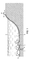
- FIG. 1 there is shown a wellhead 1 of a hydrocarbon well 2 under seawater 3.
- Wellhead 1 is provided with a protective cage 4 (an over-trawlable WHPS) to prevent damage by trawling nets and feeds hydrocarbon into minor pipeline 5.
- Hydrocarbon minor pipeline 5 and similar lines from several other wellheads feed hydrocarbon to a pipeline end module (PLEM) 6 which combines the flow and feeds it into major pipeline 7 which leads to a remote onshore receiving facility 8.
- PLEM 6 is also provided with a protective cage 9 and sensor units 10 and 11 are respectively mounted within cages 4 and 9 at a minimum height of 2 m above the seabed 12.
- Data transmission lines 13 and 14 lead from the wellhead and PLEM to a data analyser unit 15 at the onshore facility.
- a further sensor unit 16 similarly mounted within a protective cage 17 and provided with an acoustic data transmitter 18 for transmission of data to an acoustic receiver 19 on sensor unit 10.
- FIG. 2 there is shown an array of sensor units 10 on a set of wellheads 1 around PLEM 6 and a further array of outlier sensor units 16.
- cages 4, 9 and 17 are not shown.
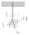
- Drill string 22 leads via wellhead 1 to hydrocarbon well 2.
- a buoyant submerged sensor unit 23 is tethered by cable 24 to seabed anchor 25 such that it is 30 m below the sea surface 24 and 100 m from legs 21.
- Data transmission line 27 leads from sensor unit 23 down cable 24, across seabed 12, and up leg 21 to a data collection unit 28.
- a seabed sensor unit 29 is tethered by cable 30 to seabed anchor 31 such that it is 2 m above the seabed and 60 m from legs 21.
- Data transmission line 32 leads from sensor unit 29 down cable 30, across seabed 12 to join with data transmission line 27.
- An outlier seabed sensor unit 33 is tethered by cable 34 to seabed anchor 35 such that it is 2 m above the seabed and 800 m from legs 21.
- Sensor unit 33 is provided with an acoustic transmitter 36 to transmit data to acoustic receiver 37 on sensor unit 29.
- a further sensor unit 38 is attached to leg 21 and is provided with a data transmission line 39 which joins data transmission line 27.
- a near-surface buoyant outlier sensor unit 41 is tethered as for sensor unit 23 but 800 m from leg 21. This sensor unit is provided with acoustic transmitter 42 which transmits data to acoustic receiver 43 on seabed outlier sensor unit 38.
- Data collected by collection unit 28 is transmitted by radio transmitter 40 to a remote data analyser (not shown).
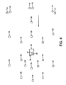
- FIG. 4 there is shown from above the drilling and/or production platform 20, the first array of submerged near-surface sensor units 26, the second array of seabed sensor units 29, outlier submerged near-surface sensor units 41, and outlier seabed sensor units 33.
- the arrow indicates the "normal" seawater current direction.
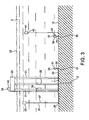
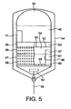
- Compartment 50 is a sealed gas-containing buoyancy tank.
- Compartment 49 is a sealed unit containing a data receiver (not shown) and carrying on its exterior an acoustic data transmitter 51.
- Compartment 48 (shown partly cut away) is a detachable two compartment tank in which upper sealed compartment 52 is filled with an organic solvent, contains an infra-red spectrophotometer 53, and is separated from lower compartment 54 by a semi-permeable membrane 55 through which organic compounds may pass.
- Lower compartment 54 has a perforated peripheral wall 56 and contains a temperature sensor 57.
- Compartment 47 (also shown partly cut away) is also detachable and has a perforated peripheral wall 58 and contains mussels 59 as the monitored biological species.
- the mussels are illuminated by light source 60 and monitored by camera 61.
- the compartments may alternatively be arranged so that samples of the sentinel species or samples from passive sampling devices may be removed while the compartments remain in situ .
- a flow meter 62 which is freely rotatable about a vertical axis and which is provided with a solid state compass (not shown) so that flow direction is also measured.
Landscapes
- Life Sciences & Earth Sciences (AREA)
- Engineering & Computer Science (AREA)
- Chemical & Material Sciences (AREA)
- Geology (AREA)
- Health & Medical Sciences (AREA)
- Physics & Mathematics (AREA)
- Mining & Mineral Resources (AREA)
- Geochemistry & Mineralogy (AREA)
- Analytical Chemistry (AREA)
- General Life Sciences & Earth Sciences (AREA)
- Environmental & Geological Engineering (AREA)
- Oil, Petroleum & Natural Gas (AREA)
- Food Science & Technology (AREA)
- Medicinal Chemistry (AREA)
- Fluid Mechanics (AREA)
- Biochemistry (AREA)
- General Health & Medical Sciences (AREA)
- General Physics & Mathematics (AREA)
- Immunology (AREA)
- Pathology (AREA)
- Testing Or Calibration Of Command Recording Devices (AREA)
- Investigating Or Analyzing Materials By The Use Of Electric Means (AREA)
Priority Applications (3)
| Application Number | Priority Date | Filing Date | Title |
|---|---|---|---|
| EP12181189.7A EP2527588A3 (en) | 2007-07-24 | 2008-07-24 | Method and apparatus for monitoring offshore contamination |
| PL08776053T PL2179130T3 (pl) | 2007-07-24 | 2008-07-24 | Sposób i urządzenie do monitorowania zanieczyszczeń w morzu |
| CY20141100254T CY1115031T1 (el) | 2007-07-24 | 2014-04-03 | Μεθοδος και διαταξη για παρακολουθηση υπερακτιας μολυνσης |
Applications Claiming Priority (2)
| Application Number | Priority Date | Filing Date | Title |
|---|---|---|---|
| GBGB0714442.1A GB0714442D0 (en) | 2007-07-24 | 2007-07-24 | Method |
| PCT/GB2008/002542 WO2009013503A1 (en) | 2007-07-24 | 2008-07-24 | Method and apparatus for monitoring offshore contamination |
Related Child Applications (2)
| Application Number | Title | Priority Date | Filing Date |
|---|---|---|---|
| EP12181189.7A Division EP2527588A3 (en) | 2007-07-24 | 2008-07-24 | Method and apparatus for monitoring offshore contamination |
| EP12181189.7 Division-Into | 2012-08-21 |
Publications (2)
| Publication Number | Publication Date |
|---|---|
| EP2179130A1 EP2179130A1 (en) | 2010-04-28 |
| EP2179130B1 true EP2179130B1 (en) | 2014-01-08 |
Family
ID=38512799
Family Applications (2)
| Application Number | Title | Priority Date | Filing Date |
|---|---|---|---|
| EP08776053.4A Not-in-force EP2179130B1 (en) | 2007-07-24 | 2008-07-24 | Method and apparatus for monitoring offshore contamination |
| EP12181189.7A Withdrawn EP2527588A3 (en) | 2007-07-24 | 2008-07-24 | Method and apparatus for monitoring offshore contamination |
Family Applications After (1)
| Application Number | Title | Priority Date | Filing Date |
|---|---|---|---|
| EP12181189.7A Withdrawn EP2527588A3 (en) | 2007-07-24 | 2008-07-24 | Method and apparatus for monitoring offshore contamination |
Country Status (14)
| Country | Link |
|---|---|
| US (1) | US8805618B2 (pl) |
| EP (2) | EP2179130B1 (pl) |
| AU (1) | AU2008278850B2 (pl) |
| BR (1) | BRPI0814586A2 (pl) |
| CA (1) | CA2694260C (pl) |
| CY (1) | CY1115031T1 (pl) |
| DK (1) | DK2179130T3 (pl) |
| EA (1) | EA019596B1 (pl) |
| ES (1) | ES2456334T3 (pl) |
| GB (1) | GB0714442D0 (pl) |
| NO (1) | NO20100105L (pl) |
| PL (1) | PL2179130T3 (pl) |
| PT (1) | PT2179130E (pl) |
| WO (1) | WO2009013503A1 (pl) |
Families Citing this family (19)
| Publication number | Priority date | Publication date | Assignee | Title |
|---|---|---|---|---|
| NO20060439L (no) * | 2006-01-26 | 2007-07-27 | Bioguard As | Fremgangsmate for a bestemme et utslipps virkning pa et marint miljo |
| GB0714442D0 (en) | 2007-07-24 | 2007-09-05 | Biota Guard As | Method |
| CA2700749C (en) | 2007-10-05 | 2016-03-22 | Exxonmobil Upstream Research Company | Method and apparatus for detection of a liquid under a surface |
| GB2467520A (en) | 2009-01-28 | 2010-08-04 | Biota Guard As | Detecting aqueous contamination using sentinel species |
| CN101520449B (zh) * | 2009-02-26 | 2012-04-25 | 孟伟 | 一种近岸海域水质采样点优化装置及优化方法 |
| GB0920796D0 (en) | 2009-11-27 | 2010-01-13 | Biotarisk As | Pollution monitoring |
| US8469090B2 (en) * | 2009-12-01 | 2013-06-25 | Schlumberger Technology Corporation | Method for monitoring hydrocarbon production |
| GB201001957D0 (en) | 2010-02-05 | 2010-03-24 | Biotarisk As | Pollution monitoring |
| US20120037378A1 (en) * | 2010-08-10 | 2012-02-16 | Vetco Gray Inc. | Tree protection system |
| GB201113784D0 (en) | 2011-08-10 | 2011-09-21 | Biotatools As | Pollution monitoring |
| NO339739B1 (no) * | 2012-07-17 | 2017-01-30 | Aker Solutions As | Undervanns lekkasjedetekteringssystem |
| EA201691157A1 (ru) | 2013-12-04 | 2016-09-30 | Эксонмобил Апстрим Рисерч Компани | Способ и система для обнаружения материала в области земли |
| CN105242007B (zh) * | 2015-09-18 | 2017-10-24 | 武汉大学 | 一种固液界面污染物释放装置 |
| US10690646B2 (en) * | 2017-12-01 | 2020-06-23 | Madison Mckensi Howard | Underwater camera and water quality monitoring system |
| CN108386164B (zh) * | 2018-03-05 | 2019-07-16 | 浙江大学 | 超重力条件下的天然气水合物热激法开采模拟装置 |
| CN109238775A (zh) * | 2018-09-08 | 2019-01-18 | 常州市环境监测中心 | 一种基于理化和生物耦合监测的原位被动采样装置及应用 |
| CN111948146A (zh) * | 2020-08-11 | 2020-11-17 | 哈尔滨工程大学 | 一种短距范围内的油污快速检测装置 |
| KR102437532B1 (ko) * | 2020-10-27 | 2022-08-29 | (주)우연시스템 | Ctd 기반 염분 농도 모니터링 시스템 |
| PL440508A1 (pl) | 2022-02-28 | 2023-09-04 | Uniwersytet Morski W Gdyni | Urządzenie do inwentaryzacji stanu technicznego stalowych części podwodnych nabrzeży portowych |
Family Cites Families (28)
| Publication number | Priority date | Publication date | Assignee | Title |
|---|---|---|---|---|
| US3770052A (en) * | 1970-01-02 | 1973-11-06 | Exxon Production Research Co | Installation of underwater pollution control apparatus |
| US4084543A (en) * | 1976-08-25 | 1978-04-18 | Tereco Corporation | Aquatic biotal monitor |
| US4448068A (en) * | 1981-08-31 | 1984-05-15 | The United States Of America As Represented By The Secretary Of The Navy | Shallow water environmental/oceanographic measurement system |
| EP0158522A3 (en) * | 1984-04-13 | 1989-04-05 | Water Research Centre | Continuous monitoring of water quality |
| US4626992A (en) * | 1984-05-21 | 1986-12-02 | Motion Analysis Systems, Inc. | Water quality early warning system |
| US4888703A (en) * | 1986-09-09 | 1989-12-19 | Hitachi Engineering Co., Ltd. | Apparatus for monitoring the toxicant contamination of water by using aquatic animals |
| US5010776A (en) * | 1989-05-04 | 1991-04-30 | Iit Research Institute | Environmental contamination detection and analyzing system and method |
| US5140855A (en) * | 1990-11-13 | 1992-08-25 | Biological Monitoring, Inc. | Monitoring tank modules and array for use with biological sensors |
| US5469144A (en) * | 1990-11-13 | 1995-11-21 | Biological Monitoring, Inc. | Method and apparatus using threshold techniques for generating an alarm in a bio-sensor |
| US5532679A (en) * | 1993-08-05 | 1996-07-02 | Baxter, Jr.; John F. | Oil spill detection system |
| FR2713778B1 (fr) | 1993-12-08 | 1996-01-26 | Inst Fs Rech Expl Mer | Appareil de détection de pollution des milieux aquatiques. |
| US5798222A (en) | 1995-07-17 | 1998-08-25 | Guava Technologies, Inc. | Apparatus for monitoring substances in organisms |
| WO1999044057A1 (en) | 1996-08-26 | 1999-09-02 | Microvolt Oy | Device and method for measuring the action potential of aquatic organisms |
| US6393899B1 (en) * | 1997-03-17 | 2002-05-28 | Geo-Centers, Inc. | Apparatus and method for automated biomonitoring of water quality |
| US6058763A (en) * | 1997-03-17 | 2000-05-09 | Geo-Centers, Inc. | Apparatus and method for automated biomonitoring of water quality |
| US6119630A (en) * | 1997-05-26 | 2000-09-19 | 3042015 Nova Scotia Limited | Installation for in situ monitoring the quality of habitat of aquatic organisms |
| DE19848230A1 (de) | 1998-10-20 | 2000-04-27 | Almut Gerhardt | Verfahren zur kontinuierlichen Gewässeranalyse |
| WO2002010707A2 (en) * | 2000-08-01 | 2002-02-07 | Aqueous Solutions, Inc. | System and method for monitoring water using bivalve mollusks |
| US8171989B2 (en) * | 2000-08-14 | 2012-05-08 | Schlumberger Technology Corporation | Well having a self-contained inter vention system |
| TW553385U (en) * | 2000-11-24 | 2003-09-11 | Hycom Instr Corp | Sensing device to detect the oil contamination on water surface |
| GB0203792D0 (en) | 2002-02-19 | 2002-04-03 | Ocean Technologies Ltd | Reusable offshore multi-functional monitoring system |
| WO2004069751A2 (en) * | 2003-02-03 | 2004-08-19 | U.S. Government As Represented By The Secretary Of The U.S. Army | Apparatus and method of portable automated biomonitoring of water quality |
| US7009550B2 (en) * | 2003-06-20 | 2006-03-07 | Peter Moeller-Jensen | Method and apparatus for monitoring and measuring oil spills |
| US6932542B2 (en) * | 2003-07-14 | 2005-08-23 | Deepwater Marine Technology L.L.C. | Tension leg platform having a lateral mooring system and methods for using and installing same |
| FR2868446A1 (fr) * | 2004-03-31 | 2005-10-07 | Jacques Edouard Flichy | Ensemble charge de recueillir les fuites de petroles d'une epave |
| NO20060439L (no) * | 2006-01-26 | 2007-07-27 | Bioguard As | Fremgangsmate for a bestemme et utslipps virkning pa et marint miljo |
| US20080217022A1 (en) * | 2007-03-06 | 2008-09-11 | Schlumberger Technology Corporation | Subsea communications multiplexer |
| GB0714442D0 (en) | 2007-07-24 | 2007-09-05 | Biota Guard As | Method |
-
2007
- 2007-07-24 GB GBGB0714442.1A patent/GB0714442D0/en not_active Ceased
-
2008
- 2008-07-24 ES ES08776053.4T patent/ES2456334T3/es active Active
- 2008-07-24 US US12/670,640 patent/US8805618B2/en not_active Expired - Fee Related
- 2008-07-24 CA CA2694260A patent/CA2694260C/en not_active Expired - Fee Related
- 2008-07-24 DK DK08776053.4T patent/DK2179130T3/da active
- 2008-07-24 EA EA201000060A patent/EA019596B1/ru not_active IP Right Cessation
- 2008-07-24 BR BRPI0814586-5A2A patent/BRPI0814586A2/pt not_active IP Right Cessation
- 2008-07-24 AU AU2008278850A patent/AU2008278850B2/en not_active Ceased
- 2008-07-24 EP EP08776053.4A patent/EP2179130B1/en not_active Not-in-force
- 2008-07-24 PL PL08776053T patent/PL2179130T3/pl unknown
- 2008-07-24 EP EP12181189.7A patent/EP2527588A3/en not_active Withdrawn
- 2008-07-24 PT PT87760534T patent/PT2179130E/pt unknown
- 2008-07-24 WO PCT/GB2008/002542 patent/WO2009013503A1/en not_active Ceased
-
2010
- 2010-01-21 NO NO20100105A patent/NO20100105L/no not_active Application Discontinuation
-
2014
- 2014-04-03 CY CY20141100254T patent/CY1115031T1/el unknown
Also Published As
| Publication number | Publication date |
|---|---|
| EP2527588A3 (en) | 2014-10-15 |
| PL2179130T3 (pl) | 2014-06-30 |
| NO20100105L (no) | 2010-04-07 |
| EP2179130A1 (en) | 2010-04-28 |
| AU2008278850A1 (en) | 2009-01-29 |
| GB0714442D0 (en) | 2007-09-05 |
| BRPI0814586A2 (pt) | 2015-01-20 |
| CA2694260C (en) | 2013-07-09 |
| CA2694260A1 (en) | 2009-01-29 |
| EA201000060A1 (ru) | 2010-08-30 |
| ES2456334T3 (es) | 2014-04-22 |
| EA019596B1 (ru) | 2014-04-30 |
| DK2179130T3 (da) | 2014-04-07 |
| US20100274491A1 (en) | 2010-10-28 |
| AU2008278850B2 (en) | 2014-06-26 |
| CY1115031T1 (el) | 2016-12-14 |
| PT2179130E (pt) | 2014-04-04 |
| US8805618B2 (en) | 2014-08-12 |
| EP2527588A2 (en) | 2012-11-28 |
| WO2009013503A1 (en) | 2009-01-29 |
| EA201000060A8 (ru) | 2012-09-28 |
Similar Documents
| Publication | Publication Date | Title |
|---|---|---|
| EP2179130B1 (en) | Method and apparatus for monitoring offshore contamination | |
| US20120046882A1 (en) | Method of detecting contamination of water using living organisms | |
| US6536272B1 (en) | Water monitoring, data collection, and transmission module | |
| Judd et al. | Contributions to atmospheric methane by natural seepages on the UK continental shelf | |
| JP5094035B2 (ja) | プランクトンの分布調査システム | |
| US9689787B2 (en) | Technical system, method and use for online measuring and monitoring of the particle contents in a flow of injection water in an underwater line | |
| AU2007207932B2 (en) | A method of determining the effect of a spill on a marine environment | |
| CN209745955U (zh) | 一种水下传感器的保护及过滤清洗设备 | |
| Godø et al. | Real time observation system for monitoring environmental impact on marine ecosystems from oil drilling operations | |
| US7559236B1 (en) | Portable profiler for profiling a marine biosphere and method of assembling the profiler | |
| Jónsdóttir et al. | Current flow and dissolved oxygen in a full-scale stocked fish-cage with and without lice shielding skirts | |
| EP2531849B1 (en) | Pollution monitoring | |
| RU2437093C1 (ru) | Система оперативного биологического мониторинга и индикации | |
| RU2395082C1 (ru) | Способ оперативной биоиндикации | |
| Diercks et al. | NIUST-Deepwater horizon oil spill response cruise | |
| Anagnostou et al. | Application of underwater passive acoustic measurements of ocean sound in precipitation estimation | |
| US20240345056A1 (en) | Systems and methods for analyzing pond water health | |
| Haeckel et al. | Assessing the risk of greenhouse gas emissions from abandoned wells, Cruise No. AL575, 27 JUNE 2022–13 JULY 2022, Kiel–Kiel, GEOSTOR leak | |
| Karlson | High resolution monitoring of harmful algal blooms and oceanographic conditions in the Skagerrak | |
| Shanaa | Modeling and plume tracking study of a Newfoundland coastal outfall | |
| Sevaldsen | Acoustics in underwater environmental monitoring | |
| Shitashima et al. | Development of environmental assessment technique for CO2 ocean sequestration | |
| Mullins et al. | Real-time environmental monitoring from a wind farm platform in the Texas hypoxia zone | |
| Belliveau et al. | New equipment for benthic habitat studies | |
| Wallmann | Guidelines for long-term monitoring |
Legal Events
| Date | Code | Title | Description |
|---|---|---|---|
| PUAI | Public reference made under article 153(3) epc to a published international application that has entered the european phase |
Free format text: ORIGINAL CODE: 0009012 |
|
| 17P | Request for examination filed |
Effective date: 20100119 |
|
| AK | Designated contracting states |
Kind code of ref document: A1 Designated state(s): AT BE BG CH CY CZ DE DK EE ES FI FR GB GR HR HU IE IS IT LI LT LU LV MC MT NL NO PL PT RO SE SI SK TR |
|
| AX | Request for extension of the european patent |
Extension state: AL BA MK RS |
|
| RAP1 | Party data changed (applicant data changed or rights of an application transferred) |
Owner name: BIOTA GUARD AS |
|
| RIN1 | Information on inventor provided before grant (corrected) |
Inventor name: SANNI, STEINAR Inventor name: ANDERSEN, ODD, KETIL |
|
| 17Q | First examination report despatched |
Effective date: 20100811 |
|
| DAX | Request for extension of the european patent (deleted) | ||
| RIN1 | Information on inventor provided before grant (corrected) |
Inventor name: ANDERSEN, ODD, KETIL Inventor name: SANNI, STEINAR Inventor name: THE OTHER INVENTORS HAVE AGREED TO WAIVE THEIR ENT |
|
| GRAP | Despatch of communication of intention to grant a patent |
Free format text: ORIGINAL CODE: EPIDOSNIGR1 |
|
| RAP1 | Party data changed (applicant data changed or rights of an application transferred) |
Owner name: BIOTA GUARD AS |
|
| GRAP | Despatch of communication of intention to grant a patent |
Free format text: ORIGINAL CODE: EPIDOSNIGR1 |
|
| INTG | Intention to grant announced |
Effective date: 20130718 |
|
| RIN1 | Information on inventor provided before grant (corrected) |
Inventor name: BLAKER, FRANK Inventor name: SONNELAND, EIRIK Inventor name: ANDERSEN, ODD, KETIL Inventor name: SANNI, STEINAR |
|
| GRAS | Grant fee paid |
Free format text: ORIGINAL CODE: EPIDOSNIGR3 |
|
| GRAA | (expected) grant |
Free format text: ORIGINAL CODE: 0009210 |
|
| AK | Designated contracting states |
Kind code of ref document: B1 Designated state(s): AT BE BG CH CY CZ DE DK EE ES FI FR GB GR HR HU IE IS IT LI LT LU LV MC MT NL NO PL PT RO SE SI SK TR |
|
| REG | Reference to a national code |
Ref country code: GB Ref legal event code: FG4D |
|
| REG | Reference to a national code |
Ref country code: CH Ref legal event code: EP |
|
| REG | Reference to a national code |
Ref country code: IE Ref legal event code: FG4D |
|
| REG | Reference to a national code |
Ref country code: AT Ref legal event code: REF Ref document number: 648896 Country of ref document: AT Kind code of ref document: T Effective date: 20140215 |
|
| REG | Reference to a national code |
Ref country code: DE Ref legal event code: R096 Ref document number: 602008029797 Country of ref document: DE Effective date: 20140220 |
|
| REG | Reference to a national code |
Ref country code: PT Ref legal event code: SC4A Free format text: AVAILABILITY OF NATIONAL TRANSLATION Effective date: 20140328 |
|
| REG | Reference to a national code |
Ref country code: DK Ref legal event code: T3 Effective date: 20140401 |
|
| REG | Reference to a national code |
Ref country code: NL Ref legal event code: T3 |
|
| REG | Reference to a national code |
Ref country code: SE Ref legal event code: TRGR Ref country code: ES Ref legal event code: FG2A Ref document number: 2456334 Country of ref document: ES Kind code of ref document: T3 Effective date: 20140422 |
|
| REG | Reference to a national code |
Ref country code: AT Ref legal event code: MK05 Ref document number: 648896 Country of ref document: AT Kind code of ref document: T Effective date: 20140108 |
|
| REG | Reference to a national code |
Ref country code: NO Ref legal event code: T2 Effective date: 20140108 |
|
| REG | Reference to a national code |
Ref country code: LT Ref legal event code: MG4D |
|
| REG | Reference to a national code |
Ref country code: GR Ref legal event code: EP Ref document number: 20140400666 Country of ref document: GR Effective date: 20140515 |
|
| REG | Reference to a national code |
Ref country code: PL Ref legal event code: T3 |
|
| PG25 | Lapsed in a contracting state [announced via postgrant information from national office to epo] |
Ref country code: LT Free format text: LAPSE BECAUSE OF FAILURE TO SUBMIT A TRANSLATION OF THE DESCRIPTION OR TO PAY THE FEE WITHIN THE PRESCRIBED TIME-LIMIT Effective date: 20140108 |
|
| PG25 | Lapsed in a contracting state [announced via postgrant information from national office to epo] |
Ref country code: AT Free format text: LAPSE BECAUSE OF FAILURE TO SUBMIT A TRANSLATION OF THE DESCRIPTION OR TO PAY THE FEE WITHIN THE PRESCRIBED TIME-LIMIT Effective date: 20140108 Ref country code: FI Free format text: LAPSE BECAUSE OF FAILURE TO SUBMIT A TRANSLATION OF THE DESCRIPTION OR TO PAY THE FEE WITHIN THE PRESCRIBED TIME-LIMIT Effective date: 20140108 |
|
| PG25 | Lapsed in a contracting state [announced via postgrant information from national office to epo] |
Ref country code: HR Free format text: LAPSE BECAUSE OF FAILURE TO SUBMIT A TRANSLATION OF THE DESCRIPTION OR TO PAY THE FEE WITHIN THE PRESCRIBED TIME-LIMIT Effective date: 20140108 Ref country code: LV Free format text: LAPSE BECAUSE OF FAILURE TO SUBMIT A TRANSLATION OF THE DESCRIPTION OR TO PAY THE FEE WITHIN THE PRESCRIBED TIME-LIMIT Effective date: 20140108 |
|
| REG | Reference to a national code |
Ref country code: DE Ref legal event code: R097 Ref document number: 602008029797 Country of ref document: DE |
|
| PG25 | Lapsed in a contracting state [announced via postgrant information from national office to epo] |
Ref country code: CZ Free format text: LAPSE BECAUSE OF FAILURE TO SUBMIT A TRANSLATION OF THE DESCRIPTION OR TO PAY THE FEE WITHIN THE PRESCRIBED TIME-LIMIT Effective date: 20140108 Ref country code: RO Free format text: LAPSE BECAUSE OF FAILURE TO SUBMIT A TRANSLATION OF THE DESCRIPTION OR TO PAY THE FEE WITHIN THE PRESCRIBED TIME-LIMIT Effective date: 20140108 Ref country code: EE Free format text: LAPSE BECAUSE OF FAILURE TO SUBMIT A TRANSLATION OF THE DESCRIPTION OR TO PAY THE FEE WITHIN THE PRESCRIBED TIME-LIMIT Effective date: 20140108 |
|
| PGFP | Annual fee paid to national office [announced via postgrant information from national office to epo] |
Ref country code: IS Payment date: 20140724 Year of fee payment: 7 Ref country code: DK Payment date: 20140722 Year of fee payment: 7 Ref country code: GR Payment date: 20140723 Year of fee payment: 7 Ref country code: NL Payment date: 20140721 Year of fee payment: 7 Ref country code: DE Payment date: 20140724 Year of fee payment: 7 Ref country code: IE Payment date: 20140701 Year of fee payment: 7 Ref country code: CY Payment date: 20140627 Year of fee payment: 7 |
|
| PLBE | No opposition filed within time limit |
Free format text: ORIGINAL CODE: 0009261 |
|
| STAA | Information on the status of an ep patent application or granted ep patent |
Free format text: STATUS: NO OPPOSITION FILED WITHIN TIME LIMIT |
|
| PG25 | Lapsed in a contracting state [announced via postgrant information from national office to epo] |
Ref country code: SK Free format text: LAPSE BECAUSE OF FAILURE TO SUBMIT A TRANSLATION OF THE DESCRIPTION OR TO PAY THE FEE WITHIN THE PRESCRIBED TIME-LIMIT Effective date: 20140108 |
|
| PGFP | Annual fee paid to national office [announced via postgrant information from national office to epo] |
Ref country code: ES Payment date: 20140729 Year of fee payment: 7 Ref country code: SE Payment date: 20140721 Year of fee payment: 7 Ref country code: PL Payment date: 20140722 Year of fee payment: 7 Ref country code: TR Payment date: 20140711 Year of fee payment: 7 Ref country code: FR Payment date: 20140731 Year of fee payment: 7 |
|
| 26N | No opposition filed |
Effective date: 20141009 |
|
| PGFP | Annual fee paid to national office [announced via postgrant information from national office to epo] |
Ref country code: PT Payment date: 20140328 Year of fee payment: 7 Ref country code: IT Payment date: 20140722 Year of fee payment: 7 |
|
| REG | Reference to a national code |
Ref country code: DE Ref legal event code: R097 Ref document number: 602008029797 Country of ref document: DE Effective date: 20141009 |
|
| PGFP | Annual fee paid to national office [announced via postgrant information from national office to epo] |
Ref country code: BE Payment date: 20140718 Year of fee payment: 7 |
|
| PG25 | Lapsed in a contracting state [announced via postgrant information from national office to epo] |
Ref country code: LU Free format text: LAPSE BECAUSE OF FAILURE TO SUBMIT A TRANSLATION OF THE DESCRIPTION OR TO PAY THE FEE WITHIN THE PRESCRIBED TIME-LIMIT Effective date: 20140724 |
|
| REG | Reference to a national code |
Ref country code: CH Ref legal event code: PL |
|
| PG25 | Lapsed in a contracting state [announced via postgrant information from national office to epo] |
Ref country code: CH Free format text: LAPSE BECAUSE OF NON-PAYMENT OF DUE FEES Effective date: 20140731 Ref country code: LI Free format text: LAPSE BECAUSE OF NON-PAYMENT OF DUE FEES Effective date: 20140731 |
|
| PG25 | Lapsed in a contracting state [announced via postgrant information from national office to epo] |
Ref country code: SI Free format text: LAPSE BECAUSE OF FAILURE TO SUBMIT A TRANSLATION OF THE DESCRIPTION OR TO PAY THE FEE WITHIN THE PRESCRIBED TIME-LIMIT Effective date: 20140108 |
|
| REG | Reference to a national code |
Ref country code: PT Ref legal event code: MM4A Free format text: LAPSE DUE TO NON-PAYMENT OF FEES Effective date: 20160125 |
|
| REG | Reference to a national code |
Ref country code: DE Ref legal event code: R119 Ref document number: 602008029797 Country of ref document: DE |
|
| REG | Reference to a national code |
Ref country code: DK Ref legal event code: EBP Effective date: 20150731 |
|
| REG | Reference to a national code |
Ref country code: SE Ref legal event code: EUG |
|
| REG | Reference to a national code |
Ref country code: NL Ref legal event code: MM Effective date: 20150801 |
|
| REG | Reference to a national code |
Ref country code: IE Ref legal event code: MM4A |
|
| PG25 | Lapsed in a contracting state [announced via postgrant information from national office to epo] |
Ref country code: IS Free format text: LAPSE BECAUSE OF FAILURE TO SUBMIT A TRANSLATION OF THE DESCRIPTION OR TO PAY THE FEE WITHIN THE PRESCRIBED TIME-LIMIT Effective date: 20160201 Ref country code: DE Free format text: LAPSE BECAUSE OF NON-PAYMENT OF DUE FEES Effective date: 20160202 Ref country code: MC Free format text: LAPSE BECAUSE OF FAILURE TO SUBMIT A TRANSLATION OF THE DESCRIPTION OR TO PAY THE FEE WITHIN THE PRESCRIBED TIME-LIMIT Effective date: 20140108 Ref country code: CY Free format text: LAPSE BECAUSE OF NON-PAYMENT OF DUE FEES Effective date: 20150724 Ref country code: IT Free format text: LAPSE BECAUSE OF NON-PAYMENT OF DUE FEES Effective date: 20150724 |
|
| REG | Reference to a national code |
Ref country code: FR Ref legal event code: ST Effective date: 20160331 |
|
| PG25 | Lapsed in a contracting state [announced via postgrant information from national office to epo] |
Ref country code: SE Free format text: LAPSE BECAUSE OF NON-PAYMENT OF DUE FEES Effective date: 20150725 Ref country code: PT Free format text: LAPSE BECAUSE OF NON-PAYMENT OF DUE FEES Effective date: 20160125 Ref country code: NL Free format text: LAPSE BECAUSE OF NON-PAYMENT OF DUE FEES Effective date: 20150801 Ref country code: FR Free format text: LAPSE BECAUSE OF NON-PAYMENT OF DUE FEES Effective date: 20150731 Ref country code: GR Free format text: LAPSE BECAUSE OF NON-PAYMENT OF DUE FEES Effective date: 20160202 Ref country code: BG Free format text: LAPSE BECAUSE OF FAILURE TO SUBMIT A TRANSLATION OF THE DESCRIPTION OR TO PAY THE FEE WITHIN THE PRESCRIBED TIME-LIMIT Effective date: 20140108 |
|
| REG | Reference to a national code |
Ref country code: GR Ref legal event code: ML Ref document number: 20140400666 Country of ref document: GR Effective date: 20160202 |
|
| PGFP | Annual fee paid to national office [announced via postgrant information from national office to epo] |
Ref country code: MT Payment date: 20140915 Year of fee payment: 7 |
|
| PG25 | Lapsed in a contracting state [announced via postgrant information from national office to epo] |
Ref country code: IE Free format text: LAPSE BECAUSE OF NON-PAYMENT OF DUE FEES Effective date: 20150724 Ref country code: HU Free format text: LAPSE BECAUSE OF FAILURE TO SUBMIT A TRANSLATION OF THE DESCRIPTION OR TO PAY THE FEE WITHIN THE PRESCRIBED TIME-LIMIT; INVALID AB INITIO Effective date: 20080724 |
|
| PG25 | Lapsed in a contracting state [announced via postgrant information from national office to epo] |
Ref country code: DK Free format text: LAPSE BECAUSE OF NON-PAYMENT OF DUE FEES Effective date: 20150731 |
|
| REG | Reference to a national code |
Ref country code: NO Ref legal event code: CHAD Owner name: IMARI AS, NO |
|
| PG25 | Lapsed in a contracting state [announced via postgrant information from national office to epo] |
Ref country code: PL Free format text: LAPSE BECAUSE OF NON-PAYMENT OF DUE FEES Effective date: 20150724 |
|
| PG25 | Lapsed in a contracting state [announced via postgrant information from national office to epo] |
Ref country code: MT Free format text: LAPSE BECAUSE OF NON-PAYMENT OF DUE FEES Effective date: 20150731 |
|
| PG25 | Lapsed in a contracting state [announced via postgrant information from national office to epo] |
Ref country code: ES Free format text: LAPSE BECAUSE OF NON-PAYMENT OF DUE FEES Effective date: 20150725 |
|
| PG25 | Lapsed in a contracting state [announced via postgrant information from national office to epo] |
Ref country code: BE Free format text: LAPSE BECAUSE OF NON-PAYMENT OF DUE FEES Effective date: 20150731 |
|
| PG25 | Lapsed in a contracting state [announced via postgrant information from national office to epo] |
Ref country code: TR Free format text: LAPSE BECAUSE OF NON-PAYMENT OF DUE FEES Effective date: 20150724 |
|
| PG25 | Lapsed in a contracting state [announced via postgrant information from national office to epo] |
Ref country code: MT Free format text: LAPSE BECAUSE OF NON-PAYMENT OF DUE FEES Effective date: 20150724 |
|
| PGFP | Annual fee paid to national office [announced via postgrant information from national office to epo] |
Ref country code: GB Payment date: 20210707 Year of fee payment: 14 |
|
| PGFP | Annual fee paid to national office [announced via postgrant information from national office to epo] |
Ref country code: NO Payment date: 20220707 Year of fee payment: 15 |
|
| GBPC | Gb: european patent ceased through non-payment of renewal fee |
Effective date: 20220724 |
|
| PG25 | Lapsed in a contracting state [announced via postgrant information from national office to epo] |
Ref country code: GB Free format text: LAPSE BECAUSE OF NON-PAYMENT OF DUE FEES Effective date: 20220724 |
|
| REG | Reference to a national code |
Ref country code: NO Ref legal event code: MMEP |
|
| PG25 | Lapsed in a contracting state [announced via postgrant information from national office to epo] |
Ref country code: NO Free format text: LAPSE BECAUSE OF NON-PAYMENT OF DUE FEES Effective date: 20230731 |