EP2178435B1 - Vorrichtung zur rehabilitation der kehlkopfhebemuskulatur - Google Patents
Vorrichtung zur rehabilitation der kehlkopfhebemuskulatur Download PDFInfo
- Publication number
- EP2178435B1 EP2178435B1 EP08794458.3A EP08794458A EP2178435B1 EP 2178435 B1 EP2178435 B1 EP 2178435B1 EP 08794458 A EP08794458 A EP 08794458A EP 2178435 B1 EP2178435 B1 EP 2178435B1
- Authority
- EP
- European Patent Office
- Prior art keywords
- leg
- electrodes
- power source
- electrode
- patient
- Prior art date
- Legal status (The legal status is an assumption and is not a legal conclusion. Google has not performed a legal analysis and makes no representation as to the accuracy of the status listed.)
- Active
Links
Images

Classifications
-
- A—HUMAN NECESSITIES
- A61—MEDICAL OR VETERINARY SCIENCE; HYGIENE
- A61N—ELECTROTHERAPY; MAGNETOTHERAPY; RADIATION THERAPY; ULTRASOUND THERAPY
- A61N1/00—Electrotherapy; Circuits therefor
- A61N1/18—Applying electric currents by contact electrodes
- A61N1/32—Applying electric currents by contact electrodes alternating or intermittent currents
- A61N1/36—Applying electric currents by contact electrodes alternating or intermittent currents for stimulation
- A61N1/3601—Applying electric currents by contact electrodes alternating or intermittent currents for stimulation of respiratory organs
-
- A—HUMAN NECESSITIES
- A61—MEDICAL OR VETERINARY SCIENCE; HYGIENE
- A61N—ELECTROTHERAPY; MAGNETOTHERAPY; RADIATION THERAPY; ULTRASOUND THERAPY
- A61N1/00—Electrotherapy; Circuits therefor
- A61N1/02—Details
- A61N1/04—Electrodes
- A61N1/0404—Electrodes for external use
- A61N1/0472—Structure-related aspects
- A61N1/0484—Garment electrodes worn by the patient
Definitions
- the current invention generally relates to a device for treating decreased laryngeal elevation. More specifically, this invention relates to a neuro-orthotic device, in combination with electrical stimulation of the submandibular muscles, to treat laryngeal elevator musculature. This invention also relates to muscle re-education and rehabilitation by using a neuro-orthotic device, in combination with electrical stimulation of the submandibular muscles, to stimulate laryngeal elevator musculature.
- Laryngeal elevation is important in the elongation of the pharyngeal-esophageal sphincter, and assistance with epiglottic closure. Often, the decrease in laryngeal elevation is due to atrophy of the laryngeal elevator musculature.
- NMES neuromuscular electrical stimulation
- One difficulty researchers face is finding the proper balance of treatment and therapy to overcome the decrease in laryngeal elevation.
- Major goals of treatment and therapy include being non-invasive to the patient, preventing disuse atrophy of the muscles, increasing range of motion, re-educating muscle functions, temporarily decreasing spasticity, and increasing local blood circulation.
- the present invention is directed to the aforementioned problems, deficiencies and goals.
- US 5,501,646 discloses a portable jaw and neck muscle exerciser device which includes a piston with a cylinder positioned coaxially with this piston, with a spring within the cylinder providing resistance against the movement of piston, and a chin cup connected to one end of the piston and cylinder combination.
- US 6,484,053 discloses a dysphagic patient treatment method in a sequential electrical stimulator, which involves triggering a stimulation generation circuit to impress high voltage stimuli to specific muscles, when a swallowing event is recognized.
- Muscle re-education, re-generation, and rehabilitation to improve laryngeal elevation using NMES are the primary goals of this inventive method and apparatus.
- the rationale is that the improved range of motion of the larynx and tongue base retraction during swallowing affects airway protection. This anterior motion of the hyolaryngeal complex is essential to improved swallow function.
- Electronic stimulation of muscles has been practiced and is understood for many muscles and muscle groups. Electronic stimulation of the muscles forces a specific muscle or muscle group and often ancillary muscles to react to the stimulus. Electronic stimulation in the present invention is directed to muscle re-education, regeneration and rehabilitation of the laryngeal elevator musculature in order to promote laryngeal elevation, but is not intended to, nor set at such a level, to initiate the swallow reflex.
- the use of electronic stimulation to promote laryngeal elevation requires that the correct muscles be exercised.
- the paired muscles of the mylohyoid, geniohyoid and the anterior belly of the digastric musculature are primarily responsible for anterior and superior movement of the hyoid bone during a swallow. This movement of the hyoid and laryngeal elevation is vital in airway protection during swallowing.
- the anterior/superior movement of the larynx helps bring the airway safely away from the path of the bolus.
- Techniques used to accentuate and prolong laryngeal elevation are used as indirect dysphagia treatment. These techniques are based on the anatomical relationship of the hyoid, larynx and cricopharyngeal region.
- a neuro-orthotic device or orthotic in combination with electronic stimulation of the laryngeal elevator musculature provides greater isolation of the muscles, and allows proper positioning and conduction of the electrodes.
- a neuro-orthotic device also improves laryngeal elevation while reducing complications associated with disorders and injuries of the central nervous system.
- a neuro-orthotic device places the patient in the proper anatomical position to receive the most efficient electronic stimulation treatment.
- the neuro-orthotic device also prevents the adverse affect of moisture and saliva contacting the electrodes.
- the protocol of this inventive method and apparatus can be used as an adjunct in the clinical treatment of a variety of neuromuscular and musculoskeletal problems.
- Neuromuscular electrical stimulation used in combination with the electrodes of the present invention and a neuro-orthotic device shows an increase of strength and range of motion, facilitating weak contractions due to upper-motor neuron lesions or disuse atrophy, and to re-educate muscles.
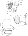
- FIG. 1 represents a first preferred embodiment of the invention.
- Apparatus 10 is the combination of neuro-orthotic device 12 and electrodes 14 and 16. Different variations of apparatus 10 may be created by using a different neuro-orthotic device 12 or different electrodes 14 and 16.
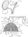
- electrodes 14 and 16 are shown with electrical leads 18 and 20. Also shown in FIGS. 1 and 5 are conductive elements 22 and 24. Electrical leads 18 and 20 provide electrical current to conductive elements 22 and 24. Electrical leads 18 and 20 are shown in FIG. 5 electrically connected to power source 26. Electrical leads 18 and 20 are shown as separate lines, but they may be combined into a single cable. The electrical current is provided and regulated by power source 26.
- Power source 26 is preferably a muscle stimulator capable of providing the protocol parameters described herein.
- a known power source 26 is the Staodyne EMS +2 manufactured by Compex Technologies, Inc.
- Other known power sources 26 include the IntelliSTIM BE-28E manufactured by EASYMED Instrument Co. Ltd; Respond Select manufactured by Empi, Inc.; BioStim NMS+ manufactured by BioMedical Life Systems, Inc.; and SYS ⁇ STIM 26 manufactured by Mettler Electronics Corporation.
- any single or plural power source 26 may be used that substantially meets the protocol requirements of the inventive method described herein.
- FIG. 6 is an exploded sectional view of electrodes taken along section line 6-6 of FIG. 5 .
- FIG. 6 depicts electrodes 14 and 16 as subcomponents.
- Conductive elements 22 and 24 are shown positioned between protective insulating covers 28 and 29 and pads 30 and 31.
- Protective insulating covers 28 and 29 may be any material that is non-conductive and electrically insulating.
- protective insulating covers 28 and 29 are fabricated out of a soft material and also provide a cushion for protection.
- Conductive elements 22 and 24 are affixed to pads 30 and 31.
- Conductive elements 22 and 24 are comprised of a series of small fibers 32 and 34.
- small fibers 32 and 34 are fabricated out of silver carbon.
- small fibers 32 and 34 are oriented on pads 30 and 31 parallel to the submandibular region 48 muscle fibers when electrodes 14 and 16 are applied to patient 40.
- Pads 30 and 31 are preferably fabricated out of a material allowing conductive elements 22 and 24 to transmit electrical current with minimal electrical loss. In the preferred embodiment, a gel pad was used for pads 30 and 31.
- Pad 30 has pad first side 36 and 37 and pad second side 38 and 39. Conductive elements 22 and 24 are affixed to pad first side 36 and 37. Pad second side 38 and 39 is preferably inherently tacky such that it will stick to patient 40, shown in FIGS. 2 and 7 . However, pad second side 38 and 39 may be coated with a tacky substance.
- Electrodes 14 and 16 are shown in FIGS. 1 , 5 and 7 as geometric shaped segments.
- the geometric shaped segment of electrodes 14 and 16 is designed to conformably place electrodes 14 and 16 on submandibular region 48, and to properly orient small fibers 32 and 34 in relation to the submandibular region 48 muscle fibers.
- Each segment has first leg 42 and 43 having a length x, and second leg 44 and 45 having a length y connected by arcuate portion 46 and 47.
- Length "x” and length "y” may be produced in different sizes to meet the needs of differently sized patients 40.
- length "x" is about 3.7 centimeters in length.
- length "y” is about 4.4 centimeters in length.
- First leg 42 and 43 has a first leg first end 42a and 43a and a first leg second end 42b and 43b.
- Second leg 44 and 45 has a second leg first end 44a and 45a and second leg second end 44b and 45b. As seen in FIG. 5 , first leg first end 42a and 43a is connected the second leg first end 44a and 45a.
- Arcuate portion 46 and 47 connects first leg second end 42b and 43b and second leg second end 44b and 45b.
- Electrodes 14 and 16 are shown as mirror images of each other, and each is sized to substantially cover one-half of submandibular region 48 of patient 40.
- FIG. 7 depicts electrodes 14 and 16 positioned upon submandibular region 48 of patient 40. Only electrodes 14 and 16 are shown in FIGS. 1 and 5-7 . Electrodes 14 and 16 are preferably used in pairs with a waveform that is biphasic. However, a single electrode 14 or 16 may be used in combination with a form of a manual probe.
- Electrodes 14 and 16 are used in combination with neuro-orthotic device 12. Electrodes 14 and 16 are shown in FIG. 1 positioned upon chin pad 50 of orthotic device 12. Neuro-orthotic device 12 may be any orthotic or neuro-orthotic that properly elevates the laryngeal elevator musculature. The preferred neuro-orthotic device 12 is a device previously marketed as the "REST-EZZZTM with ESP (Enhanced Swallow Posture)" by Restorative Medical Incorporated headquartered in Brandenburg, Kentucky. The minimum criteria in selecting neuro-orthotic device 12 are the proper positioning of the laryngeal elevator musculature and non-interference with electrodes 14 and 16. Once properly positioned, as shown in FIG.
- neuro-orthotic device 12 facilitates anterior and superior hyoidal movement while maintaining proper postural alignment with optimal contact of electrodes 14 and 16. Additionally, neuro-orthotic device 12 facilitates better contact between the submandibular region 48 musculature and electrodes 14 and 16. The better contact is achieved by patient 40 resting chin 62 upon neuro-orthotic device 12, which improves contact with the submandibular region 48 musculature.
- FIGS. 1-4 depict the preferred neuro-orthotic device 12.
- Neuro-orthotic device 12 has chin pad 50, chin pad support structure 52, chest pad 54, chest pad support structure 56, connective support structure 58, and retention strap 60.
- Chin pad 50 is designed to comfortably support chin 62 of patient 40 without interfering with electrodes 14 and 16 affixed to submandibular region 48.
- neuro-orthotic device 12 is shown with an ergonomic design to support chin 62 while keeping neuro-orthotic device 12 away from neck 64 of patient 40. Chest 66 of patient 40 is used to provide a fulcrum to support chin 62 with neuro-orthotic device 12. Retention strap 60 is shown around the back of neck 64. In this position, neuro-orthotic device 12 is held in position for treatment. Once positioned, as shown in FIG. 2 , the laryngeal elevator musculature of patient 40 is properly positioned for treatment.
- Patient 40 is depicted in FIG. 2 as a human. However, this inventive method is applicable to any animal having submandibular region 48. Usage of the term animal is meant to include all human and non-human species having a submandibular region 48.
- FIGS. 2 and 7 illustrate a preferred embodiment of the inventive method.
- electrodes 14 and 16 are affixed to submandibular region 48 of patient 40.
- Second leg 44 and 45 of electrodes 14 and 16 are placed along a line between anterior placement point 68 and posterior placement point 70 as shown in FIG. 7 .
- the unique shape of electrodes 14 and 16 ensures the proper alignment of small fibers 32 and 34 in relation to the submandibular region 48 muscle fibers.
- the placement of electrodes 14 and 16 is preferably non-invasive.
- neuro-orthotic device 12 With electrodes 14 and 16 in place, neuro-orthotic device 12 is placed under chin 62 of patient 40. Chin pad 50 of neuro-orthotic device 12 comfortably raises the submandibular region 48 of patient 40 to a proper position. In the proper position, the laryngeal elevator musculature of patient 40 is positioned for the maximum muscle re-education and rehabilitation. Chin pad 50 may be used to align electrodes 14 and 16 for initial treatment and for subsequent treatments, thus ensuring consistent or repeatable placement of electrodes 14 and 16 on submandibular region 48.
- a proper protocol is used for treatment of the patient.
- the application of the proper protocol uses a pre-determined, or sufficient, pulsed electrical current sent through electrodes 14 and 16 for a pre-determined, or sufficient, time with a pre-determined, or sufficient, electrical input.
- Pre-determined, or sufficient, power comprises a sufficient voltage, a sufficient frequency, a sufficient pulse width, a sufficient amplitude, a sufficient ramp period, and a sufficient waveform.
- Pre-determination, or sufficiency is based upon the needs of patient 40 and what is tolerable to patient 40.
- the application of a sufficient frequency produces a smooth tetanic contraction in the muscles of a submandibular region 48 without causing spasms.
- a pre-determined, or sufficient, protocol typically requires treatment twice a day for about 15 minutes.
- the duty cycle of the protocol starts about 5 seconds on and about 25 seconds off. Once patient 40 can tolerate the treatment, the duty cycle is changed to about 5 seconds on and about 15 seconds off.
- the maximum duty cycle is about a 1:1 ratio, or about 5 seconds on and about 5 seconds off.
- the preferred protocol frequency is about 30 hertz (30 pulses per second).
- the protocol pulse width is between about 240 microseconds to about 260 microseconds.
- the preferred initial trial pulse width is about 250 microseconds.
- the pulse width may be lowered between about 40 microseconds to about 60 microseconds.
- the amperage is preferably doubled.
- the protocol amperage is preferably about 10 milliamps to about 80 milliamps. However, the amperage is tied to the pulse width for maximum muscle stimulation.
- the amplitude is between about 10 milliamps to about 40 milliamps for a pulse width of about 250 microseconds.
- the amplitude is between about 30 milliamps to about 80 milliamps for a pulse width of about 50 microseconds.
- the protocol uses pulsed current. In one clinical trial the amplitude had a range of 14 milliamps to 35 milliamps for an input voltage range of 11 millivolts to 100 millivolts. The average was 18.72 milliamps and 46.04 millivolts.
- the protocol ramp, or rise in intensity, is about 0.4 seconds.
- the waveform of the protocol is preferably a symmetrical biphasic waveform when pairs of electrodes 14 and 16 are utilized.
- the current To stimulate the anterior digastric and mylohyoid muscles, the current must pass through the skin/fascia layer and platysma. The electrical current passes through these layers to the anterior digastric and mylohyoid musculature, and may overflow into other musculature such as the geniohyoid and hyoglossus.
- the benefits of stimulating this region are that they voluntarily assist the depression of the tongue via the hyoglossus and contract the digastric muscles, mylohyoid and geniohyoid muscles assisting in the anterior/superior movement of the larynx.
- the goal of using these preferred parameters of the protocol is for re-educating the laryngeal elevator musculature without inducing a swallow reflex.
- the anterior digastric muscle which originates on the inferior border of the mandible, is stimulated since it is the most superficial suprahyoidal muscle.
- the anterior digastric muscle insertion at the cornu of the hyoid acts to elevate and pull the hyoid anteriorly.
- the stimulation overflows to the mylohyoid for its origin on the mylohyoid line of the mandible and its insertion at the body of the hyoid, which acts to elevate and pull the hyoid anteriorly.
- the stimulation overflows to the hyoglossus for its origin on the hyoid bone and its insertion at the sides of the tongue which depresses the tongue.
- the stimulation may overflow to the geniohyoid which is depresses the jaw and elevates and protracts the hyoid. Origin of the geniohyoid from the inferior mental spine on the back of the symphysis menti and inserts to the hyoid bone.
- Tetanizing is a condition characterized by twitching/contracting muscles.
- Using a pulse width of about 250 microseconds increases the depth of penetration of the current. Initial trial of 250 microseconds is recommended to achieve muscle tetany. The higher the pulse width, the greater the penetration of current and the lower the intensity needed to make a contraction. The lower the pulse width, the shallower the penetration of current and the higher the intensity needed to make a contraction.
- the strength duration curve provided in Table 1 indicates that the large sensory nerves are activated first, motor nerves are activated second, and pain nerves are activated third.
- the preferred amplitude is patient variable, ranging from 10 milliamps to 100 milliamps which is sufficient to elicit a comfortable motor/tetanic response in patient 40.
- Ramp up time, or ramp time is the length of time it takes for the output stimulus to reach maximum strength for each muscle contraction. The ramp time aids in the comfort of the treatment. Typically, a ramp time of 0.4 seconds can be used to mimic normal recruitment and is suggested for the comfort of patient 40.
- the duty cycle affects the fatigue rate of patient 40. Depending upon patient 40, initial treatments for muscle re-education may require longer on/off time in the duty cycle.
- a duty cycle of about 1:3, about 5 seconds on and about 15 seconds off, is typically less fatiguing to patient 40. However, it is recommended that treatment start at a duty cycle of about 1:5, about 5 seconds on and about 25 seconds off.
- the maximum duty cycle is about 1:1, about 5 seconds on and about 5 seconds off.
- the preferred waveform is a symmetrical biphasic waveform.
- the symmetrical biphasic waveform efficiently stimulates both electrodes 14 and 16.
- the size and placement of electrodes 14 and 16 must be chosen such that they provide the desired response for patient 40 avoiding the carotid sinus.
- Any power source 26 that is a powered muscle stimulator labeled for "muscle re-education" can be used with neuro-orthotic device 12 as long as it is capable of meeting the protocol parameters and follows the manufacturers listed contraindications.
- the neuro-orthotic device 12 positions submandibular region 48 of patient 40 into a position such that the laryngeal elevator muscles are stimulated without inducing a swallowing action. This movement facilitates patterns leading to the reversal of disuse atrophy, while improved posture will enhance the ability to breathe and take in nutrition and hydration.
- Neuro-orthotic device 12 comfortably embraces submandibular region 48, and can be used as an orthosis to decrease pain from poor posture.
- this inventive method should increase the quality of life as patients will be able to take part in activities which may also improve their degree of orientation and cognition.
- neuro-orthotic device 12 can be customized to allow for accurate and easy application/removal. By using heavy gloves and moving a heat gun in a small circular motion, neuro-orthotic device 12 can be remolded to change the angle of chin pad support structure 52 or chest pad support structure 56 to lengthen or shorten the overall height.
- the evaluated patients were from multiple long term care facilities in Texas.
- Group 1 included patients receiving at least 20 therapy days of the Neuromuscular Electrical Stimulation (NMES) protocol as well as traditional therapy (59 patients).
- Group 2 included patients receiving traditional dysphagia therapy only, as would have been performed prior to any NMES modality training, or for patients who refused the NMES therapy protocol (46 patients).
- NMES Neuromuscular Electrical Stimulation
- a total of 105 patients were evaluated with the Modified Barium Swallow Study (MBSS) by a trained licensed speech language pathologist, and were found to have impaired laryngeal elevation as a primary or secondary dysfunction causing aspiration or risk of aspiration to the degree that diet changes were necessary.
- a swallow severity scale was established to determine the diet after the initial diagnosis of dysphagia using fluoroscopy.
- the subset of patients who were able to tolerate at least 20 days of traditional dysphagia therapy while also using the NMES established protocol were included in the analysis as patients having successful completion of the protocol.
- a comparison was made from a total of 46 patients who received only the traditional dysphagia therapy, but whose chart reviews noted these patients exhibited dysphagia with decreased laryngeal elevation as diagnosed from an MBSS.
- the swallow severity scale improved from a 2.25 level to a 3.6 level in the NMES subgroup receiving at least 20 days of the NMES protocol.
- the swallow severity scale improved from a 2.52 level to a 2.60 level in the traditional therapy group.
- a review of patients' charts revealed that not all of the patients were able to achieve a period of at least 20 days in the traditional therapy group.
- the average number of therapy visits in the NMES subgroup was 37.71 visits (range: 20-91).
- the average number of therapy days in the traditional study group was 19 days (range: 8-44).
- 59% of the patients who received at least 20 days of the NMES protocol had a diet upgrade, while 41% of the patients did not improve in diet upgrades.
Landscapes
- Health & Medical Sciences (AREA)
- Engineering & Computer Science (AREA)
- Biomedical Technology (AREA)
- Nuclear Medicine, Radiotherapy & Molecular Imaging (AREA)
- Radiology & Medical Imaging (AREA)
- Life Sciences & Earth Sciences (AREA)
- Animal Behavior & Ethology (AREA)
- General Health & Medical Sciences (AREA)
- Public Health (AREA)
- Veterinary Medicine (AREA)
- Physiology (AREA)
- Pulmonology (AREA)
- Electrotherapy Devices (AREA)
- Rehabilitation Tools (AREA)
Claims (13)
- Vorrichtung, die konfiguriert ist, die laryngeale Hebemuskulatur eines submandibulären Bereichs eines Patienten zu stimulieren, wobei die Vorrichtung Folgendes umfasst:ein Paar Elektroden (14, 16), das zum Übertragen eines elektrischen Stimulus angepasst ist, wobei das Paar Elektroden (14, 16) je Folgendes umfasst:ein erstes Bein (42, 43), das eine erste Länge, ein erstes Ende (42a, 43a) und ein zweites Ende (42b, 43b) aufweist;ein zweites Bein (44, 45), das eine zweite Länge, ein erstes Ende (44a, 45a) und ein zweites Ende (44b, 45b) aufweist, wobei das erste Ende (42a, 43a) des ersten Beins (42, 43) und das erste Ende (44a, 45a) des zweiten Beins (44, 45) verbunden sind;einen bogenförmigen Abschnitt (46), der das zweite Ende (42b, 43b) des ersten Beins (42, 43) mit dem zweiten Ende (44b, 45b) des zweiten Beins (44, 45) verbindet;wobei jede Elektrode (14, 16), die das Paar Elektroden bildet, eine Reihe von elektrisch leitfähigen Elementen (22, 24) umfasst, die konfiguriert sind, parallel zu den aktiven Muskelfasern des submandibulären Bereichs ausgerichtet zu sein.
- Vorrichtung nach Anspruch 1, wobei das erste Bein (42, 43) jeder Elektrode (14, 16) in Bezug auf das zweite Bein (44, 45) jeder Elektrode (14, 16) senkrecht steht.
- Vorrichtung nach Anspruch 2, ferner umfassend eine elektrische Leitung (18, 20), die mit der Reihe von elektrisch leitfähigen Elementen in jeder Elektrode verbunden ist; und eine Energiequelle (26), die angeordnet ist, um der Reihe von elektrisch leitfähigen Elementen (22, 24) über die elektrische Leitung (18, 20) einen elektrischen Strom bereitzustellen.
- Vorrichtung nach Anspruch 1, wobei die erste Länge des ersten Beins (42, 43) jeder Elektrode etwa 3,7 Zentimeter lang ist und wobei die zweite Länge des zweiten Beins (44, 45) jeder Elektrode etwa 4,4 Zentimeter lang ist.
- Vorrichtung nach Anspruch 1, wobei jede Elektrode (14, 16) bemessen ist, um eine Hälfte des submandibulären Bereichs (48) eines Patienten abzudecken.
- Vorrichtung nach Anspruch 3, wobei die Energiequelle (26) angeordnet ist, um einen elektrischen Stimulus bereitzustellen, der eine Pulsbreite zwischen etwa 240 Mikrosekunden und etwa 260 Mikrosekunden umfasst.
- Vorrichtung nach Anspruch 3, wobei die Energiequelle (26) angeordnet ist, um einen elektrischen Stimulus bereitzustellen, der eine Pulsbreite zwischen etwa 30 Mikrosekunden und etwa 260 Mikrosekunden umfasst.
- Vorrichtung nach Anspruch 3, wobei die Energiequelle (26) angeordnet ist, um einen elektrischen Stimulus bereitzustellen, der eine Amperezahl zwischen etwa 10 Milliampere und etwa 40 Milliampere umfasst.
- Vorrichtung nach Anspruch 3, wobei die Energiequelle (26) angeordnet ist, um einen elektrischen Stimulus bereitzustellen, der eine Amperezahl zwischen etwa 10 Milliampere und etwa 80 Milliampere umfasst.
- Vorrichtung nach Anspruch 3, wobei die Energiequelle (26) angeordnet ist, um einen elektrischen Stimulus bereitzustellen, der eine Rampenzeit von etwa 0,4 Sekunden aufweist.
- Vorrichtung nach Anspruch 3, wobei die Energiequelle (26) angeordnet ist, um einen elektrischen Stimulus bereitzustellen, der eine symmetrische biphasische Wellenform umfasst.
- Vorrichtung nach einem der Ansprüche 1-11, ferner umfassend:ein Kinnpolster (50);eine Kinnpolsterstützstruktur (52);wobei das Paar Elektroden (14, 16) auf dem Kinnpolster (50) positioniert ist;eine Bruststütze (56);eine verbindende Stützstruktur (58), die die Kinnstütze (52) mit der Bruststütze (56) verbindet; undeinen Halteriemen (60), der an der verbindenden Stützstruktur (58) befestigt ist.
- Vorrichtung nach einem der Ansprüche 1-12, wobei das Paar Elektroden (14, 16) von der Kinnpolsterstützstruktur (52) abnehmbar ist.
Applications Claiming Priority (2)
| Application Number | Priority Date | Filing Date | Title |
|---|---|---|---|
| US11/827,484 US7885713B2 (en) | 2007-07-11 | 2007-07-11 | Method and apparatus for laryngeal elevator musculature rehabilitation |
| PCT/US2008/008533 WO2009009128A1 (en) | 2007-07-11 | 2008-07-11 | Method and apparatus for laryngeal elevator musculature rehabilitation |
Publications (3)
| Publication Number | Publication Date |
|---|---|
| EP2178435A1 EP2178435A1 (de) | 2010-04-28 |
| EP2178435A4 EP2178435A4 (de) | 2013-01-23 |
| EP2178435B1 true EP2178435B1 (de) | 2019-10-16 |
Family
ID=40228946
Family Applications (1)
| Application Number | Title | Priority Date | Filing Date |
|---|---|---|---|
| EP08794458.3A Active EP2178435B1 (de) | 2007-07-11 | 2008-07-11 | Vorrichtung zur rehabilitation der kehlkopfhebemuskulatur |
Country Status (8)
| Country | Link |
|---|---|
| US (2) | US7885713B2 (de) |
| EP (1) | EP2178435B1 (de) |
| JP (1) | JP5153872B2 (de) |
| AU (1) | AU2008275601B2 (de) |
| CA (1) | CA2693778C (de) |
| ES (1) | ES2759370T3 (de) |
| MX (1) | MX369946B (de) |
| WO (1) | WO2009009128A1 (de) |
Families Citing this family (46)
| Publication number | Priority date | Publication date | Assignee | Title |
|---|---|---|---|---|
| CA2966418A1 (en) * | 2005-05-03 | 2006-11-09 | The University Of Western Ontario | An oral device and kit for use in association therewith |
| US7885713B2 (en) | 2007-07-11 | 2011-02-08 | Ampcare, Llc | Method and apparatus for laryngeal elevator musculature rehabilitation |
| SE532029C2 (sv) * | 2008-02-18 | 2009-10-06 | Ann-Christine Krook | Anordning för förhindrande av snarkning |
| CA2721353C (en) | 2008-04-15 | 2015-08-04 | Trudell Medical International | Swallowing air pulse therapy mouthpiece and method for the use thereof |
| US8577468B2 (en) * | 2011-09-30 | 2013-11-05 | Nyxoah SA | Apparatus and method for extending implant life using a dual power scheme |
| US9409013B2 (en) | 2009-10-20 | 2016-08-09 | Nyxoah SA | Method for controlling energy delivery as a function of degree of coupling |
| USD631969S1 (en) * | 2010-02-26 | 2011-02-01 | Hypnoz Therapeutic Devices, Inc. | Mandible cup |
| USD634015S1 (en) * | 2010-02-26 | 2011-03-08 | Hypnoz Therapeutic Devices, Inc. | Mandible cup with pad |
| US20110282248A1 (en) | 2010-03-04 | 2011-11-17 | Martin Ruth E | Portable high frequency air pulse delivery device |
| GB2479066B (en) * | 2011-04-15 | 2012-04-11 | Muthana T Hassan | Chin and neck support device |
| JP5816461B2 (ja) * | 2011-05-18 | 2015-11-18 | 仁彦 多田 | 電極パッド及びこれを備えた気道確保装置 |
| US8816814B2 (en) | 2011-08-16 | 2014-08-26 | Elwha Llc | Systematic distillation of status data responsive to whether or not a wireless signal has been received and relating to regimen compliance |
| WO2014140750A1 (en) | 2013-03-15 | 2014-09-18 | Trudell Medical International | Oral mouthpiece and method for the use thereof |
| EP3071288B1 (de) | 2013-11-19 | 2018-11-14 | The Cleveland Clinic Foundation | Verfahren zur behandlung von obstruktiver schlafapnoe mit neuromuskular stimulator |
| US12419575B2 (en) | 2014-08-08 | 2025-09-23 | Medtronic Xomed, Inc. | System and method for evoking a reflex to monitor the nerves of the larynx |
| US10582932B2 (en) | 2014-08-11 | 2020-03-10 | The Medical College Of Wisconsin | Swallow exerciser |
| US10238945B2 (en) * | 2015-04-18 | 2019-03-26 | Thomas Val Balent | Head position training device providing instant feedback |
| US10695575B1 (en) | 2016-05-10 | 2020-06-30 | Btl Medical Technologies S.R.O. | Aesthetic method of biological structure treatment by magnetic field |
| US20180001107A1 (en) | 2016-07-01 | 2018-01-04 | Btl Holdings Limited | Aesthetic method of biological structure treatment by magnetic field |
| EP3337578A2 (de) * | 2015-08-19 | 2018-06-27 | Numan, Demir | Schluckübungsvorrichtung |
| US11247039B2 (en) | 2016-05-03 | 2022-02-15 | Btl Healthcare Technologies A.S. | Device including RF source of energy and vacuum system |
| US11464993B2 (en) | 2016-05-03 | 2022-10-11 | Btl Healthcare Technologies A.S. | Device including RF source of energy and vacuum system |
| US11534619B2 (en) | 2016-05-10 | 2022-12-27 | Btl Medical Solutions A.S. | Aesthetic method of biological structure treatment by magnetic field |
| US10583287B2 (en) | 2016-05-23 | 2020-03-10 | Btl Medical Technologies S.R.O. | Systems and methods for tissue treatment |
| US10556122B1 (en) | 2016-07-01 | 2020-02-11 | Btl Medical Technologies S.R.O. | Aesthetic method of biological structure treatment by magnetic field |
| US11141219B1 (en) | 2016-08-16 | 2021-10-12 | BTL Healthcare Technologies, a.s. | Self-operating belt |
| JP2020531111A (ja) * | 2017-08-22 | 2020-11-05 | メドトロニック・ゾーメド・インコーポレーテッド | 喉頭の神経を監視するための反射を誘発するためのシステムおよび方法 |
| US11771899B2 (en) | 2018-07-10 | 2023-10-03 | The Cleveland Clinic Foundation | System and method for treating obstructive sleep apnea |
| JP7189526B2 (ja) * | 2018-08-27 | 2022-12-14 | 株式会社タニタ | 嚥下機能判定装置 |
| JP6516174B1 (ja) * | 2018-09-28 | 2019-05-22 | 医療法人ライフサポート | 嚥下運動補助装具 |
| US12156689B2 (en) | 2019-04-11 | 2024-12-03 | Btl Medical Solutions A.S. | Methods and devices for aesthetic treatment of biological structures by radiofrequency and magnetic energy |
| US12558146B2 (en) | 2019-04-11 | 2026-02-24 | Btl Medical Solutions A.S. | Methods and devices for aesthetic treatment of biological structures by radiofrequency and magnetic energy |
| PL4417249T3 (pl) | 2019-04-11 | 2026-04-20 | Btl Medical Solutions A.S. | Urządzenia do zabiegów na strukturach biologicznych za pomocą częstotliwości radiowej |
| WO2020223740A1 (en) | 2019-05-02 | 2020-11-05 | Enhale Medical, Inc. | Systems and methods for improving sleep disordered breathing |
| US11351377B2 (en) | 2019-05-03 | 2022-06-07 | The Cleveland Clinic Foundation | Intra-oral appliances and systems |
| WO2021076188A1 (en) | 2019-10-15 | 2021-04-22 | Enhale Medical, Inc. | Biased neuromodulation lead and method of using same |
| US12611545B2 (en) | 2020-05-04 | 2026-04-28 | Btl Healthcare Technologies A.S. | Device and method for unattended treatment of a patient |
| ES2993637T3 (en) | 2020-05-04 | 2025-01-03 | Btl Healthcare Technologies As | Device for unattended treatment of a patient |
| US11878167B2 (en) | 2020-05-04 | 2024-01-23 | Btl Healthcare Technologies A.S. | Device and method for unattended treatment of a patient |
| US11691010B2 (en) | 2021-01-13 | 2023-07-04 | Xii Medical, Inc. | Systems and methods for improving sleep disordered breathing |
| JP7269672B2 (ja) | 2021-07-02 | 2023-05-09 | 株式会社Dis | 顎サポート台付きems運動器具 |
| JP7495133B2 (ja) * | 2021-09-03 | 2024-06-04 | 学校法人北里研究所 | 嚥下筋力測定器 |
| CA3260012A1 (en) | 2021-10-13 | 2023-04-20 | Btl Medical Solutions A.S. | AESTHETIC TREATMENT DEVICES FOR BIOLOGICAL STRUCTURES USING RADIOFREQUENCY AND MAGNETIC ENERGY |
| US11896816B2 (en) | 2021-11-03 | 2024-02-13 | Btl Healthcare Technologies A.S. | Device and method for unattended treatment of a patient |
| JP2024034994A (ja) * | 2022-08-31 | 2024-03-13 | 計芳 鈴木 | 嚥下鍛錬装置および嚥下鍛錬システム |
| US20260097227A1 (en) | 2024-10-08 | 2026-04-09 | Btl Medical Solutions A.S. | Devices and methods for application of a magnetic field to the nervous system |
Family Cites Families (30)
| Publication number | Priority date | Publication date | Assignee | Title |
|---|---|---|---|---|
| US648053A (en) * | 1899-08-21 | 1900-04-24 | James A Ramsey | School-desk. |
| US3025858A (en) * | 1956-10-19 | 1962-03-20 | Relaxacizor Inc | Ambulatory electrical muscle stimulating device |
| US3746004A (en) * | 1971-06-14 | 1973-07-17 | B Jankelson | Disposable electrodes for electrical stimulation of muscles and nerves of the head |
| US4167190A (en) | 1977-10-21 | 1979-09-11 | Medtronic, Inc. | Pulse dosage control unit for tissue stimulation system |
| US4390023A (en) | 1981-04-30 | 1983-06-28 | Medtronic, Inc. | Patterned electrical tissue stimulator |
| US4366815A (en) * | 1981-06-04 | 1983-01-04 | Broomes Edward L C | Anti-snoring apparatus |
| US4411268A (en) | 1982-02-10 | 1983-10-25 | Medtronic, Inc. | Muscle stimulator |
| US4519400A (en) | 1983-04-01 | 1985-05-28 | Biosonics, Inc. | Method for stimulating salivation |
| US4700697A (en) * | 1985-05-09 | 1987-10-20 | Mundell Robert D | Cervical appliance to ameliorate sleep apneas |
| US4907602A (en) | 1985-10-18 | 1990-03-13 | The Mount Sinai School Of Medicine Of The City Of New York | Device for controlling the glottic opening |
| US5016647A (en) | 1985-10-18 | 1991-05-21 | Mount Sinai School Of Medicine Of The City University Of New York | Method for controlling the glottic opening |
| US4782824A (en) * | 1987-07-23 | 1988-11-08 | Davies Gerald G | External airway support |
| US5265624A (en) * | 1990-09-06 | 1993-11-30 | Edentec | Stimulation collar |
| US5133354A (en) | 1990-11-08 | 1992-07-28 | Medtronic, Inc. | Method and apparatus for improving muscle tone |
| US5501646A (en) * | 1994-08-26 | 1996-03-26 | W. G. Miller Associates | Jaw, face and neck muscle exercise apparatus |
| US5507718A (en) * | 1994-11-10 | 1996-04-16 | Kabat; Herman | Method and apparatus for applying neck traction |
| US6198970B1 (en) | 1995-10-27 | 2001-03-06 | Esd Limited Liability Company | Method and apparatus for treating oropharyngeal respiratory and oral motor neuromuscular disorders with electrical stimulation |
| US5891185A (en) | 1995-10-27 | 1999-04-06 | Esd Limited Liability Company | Method and apparatus for treating oropharyngeal disorders with electrical stimulation |
| US5725564A (en) | 1995-10-27 | 1998-03-10 | Esd Limited Liability Company | Method and apparatus for treating dysphagia with electrical stimulation |
| US7039468B2 (en) | 1995-10-27 | 2006-05-02 | Esd Limited Liability Company | Method and apparatus for treating oropharyngeal disorders with electrical stimulation |
| US7280873B2 (en) | 1995-10-27 | 2007-10-09 | Esd, Llc | Treatment of oropharyngeal disorders by application of neuromuscular electrical stimulation |
| US6668834B1 (en) * | 1996-11-01 | 2003-12-30 | Bashir Zikria | Anti-snoring apparatus |
| WO1999020339A1 (en) * | 1997-10-17 | 1999-04-29 | Respironics, Inc. | Muscle stimulating device and method for diagnosing and treating a breathing disorder |
| US6484053B2 (en) * | 2000-11-29 | 2002-11-19 | Pairash Thajchayapong | Method and apparatus for treating poor laryngeal-elevation disorder with sequential-high voltage electrical stimulation |
| AUPR586801A0 (en) * | 2001-06-22 | 2001-07-19 | Geddes, Ian | Soil control mechanism |
| US6978787B1 (en) * | 2002-04-03 | 2005-12-27 | Michael Broniatowski | Method and system for dynamic vocal fold closure with neuro-electrical stimulation |
| JP5361378B2 (ja) * | 2005-07-01 | 2013-12-04 | ザ・ユーエスエー・アズ・リプリゼンティド・バイ・ザ・セクレタリー・デパートメント・オブ・ヘルス・アンド・ヒューマン・サーヴィスィズ | 影響を受けた部分に代わる代替部位への刺激を介して運動制御を回復させるためのシステム |
| JP4934805B2 (ja) * | 2005-12-02 | 2012-05-23 | 国立大学法人東北大学 | 口腔、咽頭、喉頭機能障害予防治療用電気刺激装置 |
| JP5085059B2 (ja) * | 2006-06-28 | 2012-11-28 | 株式会社バンダイナムコゲームス | 画像生成システム、プログラム及び情報記憶媒体 |
| US7885713B2 (en) | 2007-07-11 | 2011-02-08 | Ampcare, Llc | Method and apparatus for laryngeal elevator musculature rehabilitation |
-
2007
- 2007-07-11 US US11/827,484 patent/US7885713B2/en active Active
-
2008
- 2008-07-11 EP EP08794458.3A patent/EP2178435B1/de active Active
- 2008-07-11 WO PCT/US2008/008533 patent/WO2009009128A1/en not_active Ceased
- 2008-07-11 AU AU2008275601A patent/AU2008275601B2/en active Active
- 2008-07-11 MX MX2010000417A patent/MX369946B/es active IP Right Grant
- 2008-07-11 ES ES08794458T patent/ES2759370T3/es active Active
- 2008-07-11 JP JP2010516064A patent/JP5153872B2/ja active Active
- 2008-07-11 CA CA2693778A patent/CA2693778C/en active Active
-
2011
- 2011-02-07 US US13/021,840 patent/US9031659B2/en active Active
Non-Patent Citations (1)
| Title |
|---|
| None * |
Also Published As
| Publication number | Publication date |
|---|---|
| JP5153872B2 (ja) | 2013-02-27 |
| US7885713B2 (en) | 2011-02-08 |
| WO2009009128A1 (en) | 2009-01-15 |
| AU2008275601B2 (en) | 2012-03-29 |
| EP2178435A1 (de) | 2010-04-28 |
| EP2178435A4 (de) | 2013-01-23 |
| MX2010000417A (es) | 2010-06-25 |
| MX369946B (es) | 2019-11-27 |
| US9031659B2 (en) | 2015-05-12 |
| ES2759370T3 (es) | 2020-05-08 |
| US20110190848A1 (en) | 2011-08-04 |
| US20090018611A1 (en) | 2009-01-15 |
| CA2693778A1 (en) | 2009-01-15 |
| CA2693778C (en) | 2014-09-23 |
| JP2010533031A (ja) | 2010-10-21 |
| AU2008275601A1 (en) | 2009-01-15 |
Similar Documents
| Publication | Publication Date | Title |
|---|---|---|
| CA2693778C (en) | Method and apparatus for laryngeal elevator musculature rehabilitation | |
| US7725193B1 (en) | Intramuscular stimulation therapy using surface-applied localized electrical stimulation | |
| Inanici et al. | Transcutaneous electrical spinal stimulation promotes long-term recovery of upper extremity function in chronic tetraplegia | |
| Carhart et al. | Epidural spinal-cord stimulation facilitates recovery of functional walking following incomplete spinal-cord injury | |
| Mushahwar et al. | New functional electrical stimulation approaches to standing and walking | |
| Popović et al. | Electrical stimulation as a means for achieving recovery of function in stroke patients | |
| US9907958B2 (en) | High density epidural stimulation for facilitation of locomotion, posture, voluntary movement, and recovery of autonomic, sexual, vasomotor, and cognitive function after neurological injury | |
| JP4395754B2 (ja) | 上気道および嚥下筋群の筋肉内刺激のための方法およびデバイス | |
| US20180353755A1 (en) | Epidural stimulation for facilitation of locomotion, posture, voluntary movement, and recovery of autonomic, sexual, vasomotor, and cognitive function after neurological injury | |
| RU2475283C2 (ru) | Способ восстановления движений рук у больных с верхними параличами и парезами | |
| JP4934805B2 (ja) | 口腔、咽頭、喉頭機能障害予防治療用電気刺激装置 | |
| CN108136177A (zh) | 用于对脊髓进行经皮电刺激的电极阵列及其用途 | |
| CN111770773A (zh) | 使用通过表面电极施加的电刺激引起吞咽 | |
| KR20140098780A (ko) | 운동, 감각, 자율적, 성적, 혈관운동 및 인식 기능의 복원을 가능하게 하기 위한 비침습성 신경조절 디바이스 | |
| TWI826150B (zh) | 可編程rTMS裝置、rTMS裝置和可編程系統、電刺激裝置 | |
| US11311723B2 (en) | Motor devices for motor nerve root stimulation | |
| Saxena et al. | Functional electrical stimulation as a significant bioelectronic intervention in the domain of fitness: A review | |
| US20200009385A1 (en) | Methods of bypassing neurological damage through motor nerve root stimulation | |
| Gorman | An update on functional electrical stimulation after spinal cord injury | |
| Park et al. | Electrical characterization of the tongue and the soft palate using lumped-element model for intraoral neuromodulation | |
| US20240307679A1 (en) | Using pogo pins for electro-stimulation | |
| US7228180B1 (en) | Methods for treating victims of cerebrovascular disease | |
| AU2012203808A1 (en) | Method and apparatus for laryngeal elevator musculature rehabilitation | |
| Steele | Electrical stimulation of the pharyngeal swallow: does the evidence support application in clinical practice? | |
| Gorman et al. | Functional electrical stimulation in neurorehabilitation |
Legal Events
| Date | Code | Title | Description |
|---|---|---|---|
| PUAI | Public reference made under article 153(3) epc to a published international application that has entered the european phase |
Free format text: ORIGINAL CODE: 0009012 |
|
| 17P | Request for examination filed |
Effective date: 20100211 |
|
| AK | Designated contracting states |
Kind code of ref document: A1 Designated state(s): AT BE BG CH CY CZ DE DK EE ES FI FR GB GR HR HU IE IS IT LI LT LU LV MC MT NL NO PL PT RO SE SI SK TR |
|
| AX | Request for extension of the european patent |
Extension state: AL BA MK RS |
|
| DAX | Request for extension of the european patent (deleted) | ||
| A4 | Supplementary search report drawn up and despatched |
Effective date: 20130104 |
|
| RIC1 | Information provided on ipc code assigned before grant |
Ipc: A61N 1/04 20060101ALI20121220BHEP Ipc: A61N 1/36 20060101ALI20121220BHEP Ipc: A61B 5/04 20060101AFI20121220BHEP |
|
| STAA | Information on the status of an ep patent application or granted ep patent |
Free format text: STATUS: EXAMINATION IS IN PROGRESS |
|
| 17Q | First examination report despatched |
Effective date: 20170727 |
|
| RIC1 | Information provided on ipc code assigned before grant |
Ipc: A61N 1/04 20060101ALI20180725BHEP Ipc: A61N 1/36 20060101ALI20180725BHEP Ipc: A61B 5/04 20060101AFI20180725BHEP |
|
| GRAP | Despatch of communication of intention to grant a patent |
Free format text: ORIGINAL CODE: EPIDOSNIGR1 |
|
| STAA | Information on the status of an ep patent application or granted ep patent |
Free format text: STATUS: GRANT OF PATENT IS INTENDED |
|
| INTG | Intention to grant announced |
Effective date: 20180924 |
|
| GRAJ | Information related to disapproval of communication of intention to grant by the applicant or resumption of examination proceedings by the epo deleted |
Free format text: ORIGINAL CODE: EPIDOSDIGR1 |
|
| STAA | Information on the status of an ep patent application or granted ep patent |
Free format text: STATUS: EXAMINATION IS IN PROGRESS |
|
| INTC | Intention to grant announced (deleted) | ||
| GRAP | Despatch of communication of intention to grant a patent |
Free format text: ORIGINAL CODE: EPIDOSNIGR1 |
|
| STAA | Information on the status of an ep patent application or granted ep patent |
Free format text: STATUS: GRANT OF PATENT IS INTENDED |
|
| INTG | Intention to grant announced |
Effective date: 20190327 |
|
| GRAJ | Information related to disapproval of communication of intention to grant by the applicant or resumption of examination proceedings by the epo deleted |
Free format text: ORIGINAL CODE: EPIDOSDIGR1 |
|
| STAA | Information on the status of an ep patent application or granted ep patent |
Free format text: STATUS: EXAMINATION IS IN PROGRESS |
|
| GRAR | Information related to intention to grant a patent recorded |
Free format text: ORIGINAL CODE: EPIDOSNIGR71 |
|
| GRAS | Grant fee paid |
Free format text: ORIGINAL CODE: EPIDOSNIGR3 |
|
| STAA | Information on the status of an ep patent application or granted ep patent |
Free format text: STATUS: GRANT OF PATENT IS INTENDED |
|
| INTC | Intention to grant announced (deleted) | ||
| GRAA | (expected) grant |
Free format text: ORIGINAL CODE: 0009210 |
|
| STAA | Information on the status of an ep patent application or granted ep patent |
Free format text: STATUS: THE PATENT HAS BEEN GRANTED |
|
| RAP1 | Party data changed (applicant data changed or rights of an application transferred) |
Owner name: AMPCARE, LLC |
|
| AK | Designated contracting states |
Kind code of ref document: B1 Designated state(s): AT BE BG CH CY CZ DE DK EE ES FI FR GB GR HR HU IE IS IT LI LT LU LV MC MT NL NO PL PT RO SE SI SK TR |
|
| INTG | Intention to grant announced |
Effective date: 20190906 |
|
| REG | Reference to a national code |
Ref country code: GB Ref legal event code: FG4D |
|
| REG | Reference to a national code |
Ref country code: CH Ref legal event code: EP |
|
| REG | Reference to a national code |
Ref country code: DE Ref legal event code: R096 Ref document number: 602008061433 Country of ref document: DE |
|
| REG | Reference to a national code |
Ref country code: IE Ref legal event code: FG4D |
|
| REG | Reference to a national code |
Ref country code: AT Ref legal event code: REF Ref document number: 1190492 Country of ref document: AT Kind code of ref document: T Effective date: 20191115 |
|
| REG | Reference to a national code |
Ref country code: NL Ref legal event code: FP |
|
| REG | Reference to a national code |
Ref country code: LT Ref legal event code: MG4D |
|
| REG | Reference to a national code |
Ref country code: AT Ref legal event code: MK05 Ref document number: 1190492 Country of ref document: AT Kind code of ref document: T Effective date: 20191016 |
|
| PG25 | Lapsed in a contracting state [announced via postgrant information from national office to epo] |
Ref country code: LT Free format text: LAPSE BECAUSE OF FAILURE TO SUBMIT A TRANSLATION OF THE DESCRIPTION OR TO PAY THE FEE WITHIN THE PRESCRIBED TIME-LIMIT Effective date: 20191016 Ref country code: LV Free format text: LAPSE BECAUSE OF FAILURE TO SUBMIT A TRANSLATION OF THE DESCRIPTION OR TO PAY THE FEE WITHIN THE PRESCRIBED TIME-LIMIT Effective date: 20191016 Ref country code: SE Free format text: LAPSE BECAUSE OF FAILURE TO SUBMIT A TRANSLATION OF THE DESCRIPTION OR TO PAY THE FEE WITHIN THE PRESCRIBED TIME-LIMIT Effective date: 20191016 Ref country code: AT Free format text: LAPSE BECAUSE OF FAILURE TO SUBMIT A TRANSLATION OF THE DESCRIPTION OR TO PAY THE FEE WITHIN THE PRESCRIBED TIME-LIMIT Effective date: 20191016 Ref country code: PL Free format text: LAPSE BECAUSE OF FAILURE TO SUBMIT A TRANSLATION OF THE DESCRIPTION OR TO PAY THE FEE WITHIN THE PRESCRIBED TIME-LIMIT Effective date: 20191016 Ref country code: GR Free format text: LAPSE BECAUSE OF FAILURE TO SUBMIT A TRANSLATION OF THE DESCRIPTION OR TO PAY THE FEE WITHIN THE PRESCRIBED TIME-LIMIT Effective date: 20200117 Ref country code: NO Free format text: LAPSE BECAUSE OF FAILURE TO SUBMIT A TRANSLATION OF THE DESCRIPTION OR TO PAY THE FEE WITHIN THE PRESCRIBED TIME-LIMIT Effective date: 20200116 Ref country code: PT Free format text: LAPSE BECAUSE OF FAILURE TO SUBMIT A TRANSLATION OF THE DESCRIPTION OR TO PAY THE FEE WITHIN THE PRESCRIBED TIME-LIMIT Effective date: 20200217 Ref country code: FI Free format text: LAPSE BECAUSE OF FAILURE TO SUBMIT A TRANSLATION OF THE DESCRIPTION OR TO PAY THE FEE WITHIN THE PRESCRIBED TIME-LIMIT Effective date: 20191016 Ref country code: BG Free format text: LAPSE BECAUSE OF FAILURE TO SUBMIT A TRANSLATION OF THE DESCRIPTION OR TO PAY THE FEE WITHIN THE PRESCRIBED TIME-LIMIT Effective date: 20200116 |
|
| REG | Reference to a national code |
Ref country code: ES Ref legal event code: FG2A Ref document number: 2759370 Country of ref document: ES Kind code of ref document: T3 Effective date: 20200508 |
|
| PG25 | Lapsed in a contracting state [announced via postgrant information from national office to epo] |
Ref country code: HR Free format text: LAPSE BECAUSE OF FAILURE TO SUBMIT A TRANSLATION OF THE DESCRIPTION OR TO PAY THE FEE WITHIN THE PRESCRIBED TIME-LIMIT Effective date: 20191016 Ref country code: IS Free format text: LAPSE BECAUSE OF FAILURE TO SUBMIT A TRANSLATION OF THE DESCRIPTION OR TO PAY THE FEE WITHIN THE PRESCRIBED TIME-LIMIT Effective date: 20200224 |
|
| REG | Reference to a national code |
Ref country code: DE Ref legal event code: R097 Ref document number: 602008061433 Country of ref document: DE |
|
| PG2D | Information on lapse in contracting state deleted |
Ref country code: IS |
|
| PG25 | Lapsed in a contracting state [announced via postgrant information from national office to epo] |
Ref country code: IS Free format text: LAPSE BECAUSE OF FAILURE TO SUBMIT A TRANSLATION OF THE DESCRIPTION OR TO PAY THE FEE WITHIN THE PRESCRIBED TIME-LIMIT Effective date: 20200216 Ref country code: RO Free format text: LAPSE BECAUSE OF FAILURE TO SUBMIT A TRANSLATION OF THE DESCRIPTION OR TO PAY THE FEE WITHIN THE PRESCRIBED TIME-LIMIT Effective date: 20191016 Ref country code: CZ Free format text: LAPSE BECAUSE OF FAILURE TO SUBMIT A TRANSLATION OF THE DESCRIPTION OR TO PAY THE FEE WITHIN THE PRESCRIBED TIME-LIMIT Effective date: 20191016 Ref country code: EE Free format text: LAPSE BECAUSE OF FAILURE TO SUBMIT A TRANSLATION OF THE DESCRIPTION OR TO PAY THE FEE WITHIN THE PRESCRIBED TIME-LIMIT Effective date: 20191016 Ref country code: DK Free format text: LAPSE BECAUSE OF FAILURE TO SUBMIT A TRANSLATION OF THE DESCRIPTION OR TO PAY THE FEE WITHIN THE PRESCRIBED TIME-LIMIT Effective date: 20191016 |
|
| PLBE | No opposition filed within time limit |
Free format text: ORIGINAL CODE: 0009261 |
|
| STAA | Information on the status of an ep patent application or granted ep patent |
Free format text: STATUS: NO OPPOSITION FILED WITHIN TIME LIMIT |
|
| PG25 | Lapsed in a contracting state [announced via postgrant information from national office to epo] |
Ref country code: SK Free format text: LAPSE BECAUSE OF FAILURE TO SUBMIT A TRANSLATION OF THE DESCRIPTION OR TO PAY THE FEE WITHIN THE PRESCRIBED TIME-LIMIT Effective date: 20191016 |
|
| 26N | No opposition filed |
Effective date: 20200717 |
|
| REG | Reference to a national code |
Ref country code: DE Ref legal event code: R079 Ref document number: 602008061433 Country of ref document: DE Free format text: PREVIOUS MAIN CLASS: A61B0005040000 Ipc: A61B0005240000 |
|
| PG25 | Lapsed in a contracting state [announced via postgrant information from national office to epo] |
Ref country code: SI Free format text: LAPSE BECAUSE OF FAILURE TO SUBMIT A TRANSLATION OF THE DESCRIPTION OR TO PAY THE FEE WITHIN THE PRESCRIBED TIME-LIMIT Effective date: 20191016 |
|
| PG25 | Lapsed in a contracting state [announced via postgrant information from national office to epo] |
Ref country code: MC Free format text: LAPSE BECAUSE OF FAILURE TO SUBMIT A TRANSLATION OF THE DESCRIPTION OR TO PAY THE FEE WITHIN THE PRESCRIBED TIME-LIMIT Effective date: 20191016 |
|
| REG | Reference to a national code |
Ref country code: CH Ref legal event code: PL |
|
| REG | Reference to a national code |
Ref country code: BE Ref legal event code: MM Effective date: 20200731 |
|
| PG25 | Lapsed in a contracting state [announced via postgrant information from national office to epo] |
Ref country code: LU Free format text: LAPSE BECAUSE OF NON-PAYMENT OF DUE FEES Effective date: 20200711 Ref country code: CH Free format text: LAPSE BECAUSE OF NON-PAYMENT OF DUE FEES Effective date: 20200731 Ref country code: LI Free format text: LAPSE BECAUSE OF NON-PAYMENT OF DUE FEES Effective date: 20200731 |
|
| PG25 | Lapsed in a contracting state [announced via postgrant information from national office to epo] |
Ref country code: BE Free format text: LAPSE BECAUSE OF NON-PAYMENT OF DUE FEES Effective date: 20200731 |
|
| PG25 | Lapsed in a contracting state [announced via postgrant information from national office to epo] |
Ref country code: TR Free format text: LAPSE BECAUSE OF FAILURE TO SUBMIT A TRANSLATION OF THE DESCRIPTION OR TO PAY THE FEE WITHIN THE PRESCRIBED TIME-LIMIT Effective date: 20191016 Ref country code: MT Free format text: LAPSE BECAUSE OF FAILURE TO SUBMIT A TRANSLATION OF THE DESCRIPTION OR TO PAY THE FEE WITHIN THE PRESCRIBED TIME-LIMIT Effective date: 20191016 Ref country code: CY Free format text: LAPSE BECAUSE OF FAILURE TO SUBMIT A TRANSLATION OF THE DESCRIPTION OR TO PAY THE FEE WITHIN THE PRESCRIBED TIME-LIMIT Effective date: 20191016 |
|
| PGFP | Annual fee paid to national office [announced via postgrant information from national office to epo] |
Ref country code: NL Payment date: 20250721 Year of fee payment: 18 |
|
| PGFP | Annual fee paid to national office [announced via postgrant information from national office to epo] |
Ref country code: ES Payment date: 20250826 Year of fee payment: 18 |
|
| PGFP | Annual fee paid to national office [announced via postgrant information from national office to epo] |
Ref country code: DE Payment date: 20250722 Year of fee payment: 18 |
|
| PGFP | Annual fee paid to national office [announced via postgrant information from national office to epo] |
Ref country code: IT Payment date: 20250724 Year of fee payment: 18 |
|
| PGFP | Annual fee paid to national office [announced via postgrant information from national office to epo] |
Ref country code: GB Payment date: 20250722 Year of fee payment: 18 |
|
| PGFP | Annual fee paid to national office [announced via postgrant information from national office to epo] |
Ref country code: FR Payment date: 20250724 Year of fee payment: 18 |
|
| PGFP | Annual fee paid to national office [announced via postgrant information from national office to epo] |
Ref country code: IE Payment date: 20250723 Year of fee payment: 18 |