EP2178063B1 - Driver assistance system for motor vehicles - Google Patents
Driver assistance system for motor vehicles Download PDFInfo
- Publication number
- EP2178063B1 EP2178063B1 EP09168064.5A EP09168064A EP2178063B1 EP 2178063 B1 EP2178063 B1 EP 2178063B1 EP 09168064 A EP09168064 A EP 09168064A EP 2178063 B1 EP2178063 B1 EP 2178063B1
- Authority
- EP
- European Patent Office
- Prior art keywords
- driver assistance
- assistance system
- abovementioned
- evaluation unit
- display
- Prior art date
- Legal status (The legal status is an assumption and is not a legal conclusion. Google has not performed a legal analysis and makes no representation as to the accuracy of the status listed.)
- Active
Links
- 238000011156 evaluation Methods 0.000 claims description 29
- 238000005259 measurement Methods 0.000 claims description 25
- 230000007613 environmental effect Effects 0.000 claims description 22
- 238000012935 Averaging Methods 0.000 claims description 10
- 235000004522 Pentaglottis sempervirens Nutrition 0.000 claims description 5
- 239000003086 colorant Substances 0.000 claims description 2
- 238000012545 processing Methods 0.000 claims description 2
- 238000012937 correction Methods 0.000 description 9
- 238000000034 method Methods 0.000 description 6
- 238000011161 development Methods 0.000 description 4
- 241001465754 Metazoa Species 0.000 description 3
- 230000001419 dependent effect Effects 0.000 description 3
- 238000013461 design Methods 0.000 description 3
- 230000009897 systematic effect Effects 0.000 description 3
- 238000010276 construction Methods 0.000 description 2
- 238000001514 detection method Methods 0.000 description 2
- 240000004050 Pentaglottis sempervirens Species 0.000 description 1
- 230000003044 adaptive effect Effects 0.000 description 1
- 230000010354 integration Effects 0.000 description 1
- 238000012986 modification Methods 0.000 description 1
- 230000004048 modification Effects 0.000 description 1
- 238000012544 monitoring process Methods 0.000 description 1
- 229920001690 polydopamine Polymers 0.000 description 1
Images

Classifications
-
- G—PHYSICS
- G01—MEASURING; TESTING
- G01C—MEASURING DISTANCES, LEVELS OR BEARINGS; SURVEYING; NAVIGATION; GYROSCOPIC INSTRUMENTS; PHOTOGRAMMETRY OR VIDEOGRAMMETRY
- G01C21/00—Navigation; Navigational instruments not provided for in groups G01C1/00 - G01C19/00
- G01C21/26—Navigation; Navigational instruments not provided for in groups G01C1/00 - G01C19/00 specially adapted for navigation in a road network
- G01C21/34—Route searching; Route guidance
- G01C21/36—Input/output arrangements for on-board computers
- G01C21/3697—Output of additional, non-guidance related information, e.g. low fuel level
-
- B—PERFORMING OPERATIONS; TRANSPORTING
- B60—VEHICLES IN GENERAL
- B60W—CONJOINT CONTROL OF VEHICLE SUB-UNITS OF DIFFERENT TYPE OR DIFFERENT FUNCTION; CONTROL SYSTEMS SPECIALLY ADAPTED FOR HYBRID VEHICLES; ROAD VEHICLE DRIVE CONTROL SYSTEMS FOR PURPOSES NOT RELATED TO THE CONTROL OF A PARTICULAR SUB-UNIT
- B60W40/00—Estimation or calculation of non-directly measurable driving parameters for road vehicle drive control systems not related to the control of a particular sub unit, e.g. by using mathematical models
- B60W40/02—Estimation or calculation of non-directly measurable driving parameters for road vehicle drive control systems not related to the control of a particular sub unit, e.g. by using mathematical models related to ambient conditions
- B60W40/04—Traffic conditions
-
- B—PERFORMING OPERATIONS; TRANSPORTING
- B60—VEHICLES IN GENERAL
- B60W—CONJOINT CONTROL OF VEHICLE SUB-UNITS OF DIFFERENT TYPE OR DIFFERENT FUNCTION; CONTROL SYSTEMS SPECIALLY ADAPTED FOR HYBRID VEHICLES; ROAD VEHICLE DRIVE CONTROL SYSTEMS FOR PURPOSES NOT RELATED TO THE CONTROL OF A PARTICULAR SUB-UNIT
- B60W50/00—Details of control systems for road vehicle drive control not related to the control of a particular sub-unit, e.g. process diagnostic or vehicle driver interfaces
- B60W50/08—Interaction between the driver and the control system
- B60W50/14—Means for informing the driver, warning the driver or prompting a driver intervention
-
- G—PHYSICS
- G01—MEASURING; TESTING
- G01C—MEASURING DISTANCES, LEVELS OR BEARINGS; SURVEYING; NAVIGATION; GYROSCOPIC INSTRUMENTS; PHOTOGRAMMETRY OR VIDEOGRAMMETRY
- G01C21/00—Navigation; Navigational instruments not provided for in groups G01C1/00 - G01C19/00
- G01C21/26—Navigation; Navigational instruments not provided for in groups G01C1/00 - G01C19/00 specially adapted for navigation in a road network
-
- G—PHYSICS
- G08—SIGNALLING
- G08G—TRAFFIC CONTROL SYSTEMS
- G08G1/00—Traffic control systems for road vehicles
- G08G1/16—Anti-collision systems
- G08G1/166—Anti-collision systems for active traffic, e.g. moving vehicles, pedestrians, bikes
-
- G—PHYSICS
- G08—SIGNALLING
- G08G—TRAFFIC CONTROL SYSTEMS
- G08G1/00—Traffic control systems for road vehicles
- G08G1/16—Anti-collision systems
- G08G1/167—Driving aids for lane monitoring, lane changing, e.g. blind spot detection
-
- G—PHYSICS
- G08—SIGNALLING
- G08G—TRAFFIC CONTROL SYSTEMS
- G08G1/00—Traffic control systems for road vehicles
- G08G1/16—Anti-collision systems
- G08G1/168—Driving aids for parking, e.g. acoustic or visual feedback on parking space
Definitions
- the invention relates to a driver assistance system for motor vehicles according to the claims.
- a head-up display (HUD) control unit that can display markers at the correct distance relative to a preceding vehicle.
- a method and system for controlling a vehicle is known. Taking into account map data and sensor data, an overtaking situation of a vehicle is determined. If the situation is dangerous, the vehicle drivetrain is intervened.
- the object of the invention is to propose an improved driver assistance system for motor vehicles, by which the safety in road traffic can be increased.
- the object is achieved on the basis of a driver assistance system for motor vehicles of the type mentioned by the characterizing features of claim 1.
- an inventive driver assistance system for motor vehicles with at least one sensor device for detection and position determination of objects in the environment of the motor vehicle, with at least one evaluation unit for processing and / or evaluation of the sensor data of the sensor device and forwarding to a display device
- the evaluation unit means for correcting measurement errors, which use a plurality of sensor data of at least one sensor device with respect to an object in order to determine therefrom a coordinate of the object or an inventive driver assistance system for motor vehicles, characterized in that the evaluation unit comprises means for correcting measurement errors, the Environmental coordinates of a navigation system together with sensor data of at least one sensor device with respect to use an object to determine a coordinate of the object.
- Sensor devices in particular those for detecting and determining the position of objects in the surroundings of an observer, perform measurements.
- the sensor data and / or environment coordinates thus obtained can be subject to a number of measurement errors. These can be both systematic and statistical errors.
- Systematic measurement errors are usually determined by the measurement methodology itself. Especially in the context of driver assistance systems, the occurrence of such measurement errors can significantly unsettle the driver, under certain circumstances even jeopardize. For example, due to measurement errors, the position of an object such as an obstacle or another motor vehicle involved in road traffic can be displayed incorrectly.
- the evaluation unit comprises means for correcting measurement errors which use sensor data of at least one sensor device with respect to an object or additionally the environmental coordinates of a navigation system in order to determine therefrom a coordinate of the object. For example, new object coordinates can also be calculated.
- the driver is no longer dependent on relying on the fact that the sensor data or environmental coordinates used do not currently constitute so-called "measurement outliers" at the current time and thus indicate an indication which may well be very far from reality.
- sensor data is to be understood as a general term for data or measured values of sensors, for example camera units, vehicle-internal or external measuring and determination systems.
- environmental coordinate Consequently, for the purposes of the invention, sensor data or, for example, data of a navigation system provide information about the position of objects in the surroundings of the motor vehicle.
- very precise position determinations can be obtained via a so-called navigation system.
- the position of the vehicle is determined and associated with information of an existing road map system.
- Such a navigation system can therefore be eminently suitable for supplying corresponding environmental coordinates to the evaluation unit and thus also contribute to an improved correction of measurement errors.
- the evaluation unit may comprise means for correcting measurement errors which associate the sensor data of a sensor device with further sensor data of another sensor device and generates further data therefrom.
- the sensor data of a sensor device can be compared with those of a further sensor device, so that it can be concluded from whether sensor data are reliable or plausible during a measurement or not.
- a vehicle whose coordinates have been determined could be assigned a lane by means of environmental coordinates of a navigation system, the navigation system determining the vehicle, e.g. recognizes as a "ghost driver".
- the vehicle could also be assigned a position outside of any lane so that it is either an exceptional situation, e.g. an accident, or possibly also an implausible assignment.
- the evaluation unit comprises means for correcting measurement errors, which assigns sensor data and / or environmental coordinates of a navigation system to the coordinates of the object and generates further data therefrom.
- the coordinates of an object determined by the evaluation unit can be associated with sensor data or environmental coordinates of a navigation system in order thus to obtain further information.
- the evaluation unit comprises a statistical averaging unit for averaging sensor data and / or environmental coordinates.
- a statistical averaging is a comparatively simple and expedient measure for making corrections of measurement errors. In particular statistical errors can be corrected as a rule.
- an averaging can also take place particularly advantageously if it is not only averaged over different sensor data or environmental coordinates that can be assigned to a single sensor, but also averaged over those measured values from at least two different sensors come.
- At least one further sensor device and / or a camera for the delivery of Sensor data and / or environmental coordinates is provided to the evaluation unit / are.
- sensor devices for detecting or determining the position of objects of the surroundings of the motor vehicle are meant among others.
- other types of sensor devices in addition, for example, those sensors which provide information about the visibility, for example, whether the view is being influenced by fog or rain. This information could be used inter alia to adjust the weighting in averaging.
- a camera is conceivable. Both by means of such a camera and as a result of carrying out several measurements in succession by at least one sensor device, it is possible in embodiments of the invention to also represent moving objects.
- environment sensors are, for example, RADAR, LIDAR, in particular for longitudinal guidance of the vehicle, in particular in connection with ACC systems (English: Active / Adaptive Cruise Control, distance and speed controller), environment sensors for safety applications, eg PSS (Prodecitve safety system, vehicle brake system) Further environment sensors eg for parking systems such as park pilots, extended park pilot systems or so-called “backing aid systems", but also environment sensors for monitoring functions of the vehicle rear or vehicle side space (LCA). Also conceivable is the use of 3D representations.
- a sensor device for detecting a traffic lane in a preferred embodiment of the invention.
- the driver it may be helpful to know not only the coordinates of a particular object or the distance this object has to its vehicle, but e.g. Also, what position has a corresponding object in relation to its lane.
- Particularly important examples of this are, for example, an animal that is located directly on the roadside, a ghost driver or another, oncoming vehicle, for example, performs a dangerous overtaking maneuver.
- a determination of the distance to the lane edge which should be corrected when passing through construction sites, or a distance determination to parked vehicles.
- warning devices in one embodiment of the invention.
- corresponding hazard parameters are not only determined but also trigger warnings for the driver or the user.
- These may be colorations of specific objects, e.g. in red, but also to audible warnings, flashing indicators or the like act. This also allows the safety for the driver can be significantly improved again.
- a display device is present, in a particularly preferred manner a HUD.
- Such projection display devices already exist as established display systems in motor vehicles, aircraft, etc.
- all embodiments of HUDs such as i-HUDs (inverse HUD), which have a driver observation system, HUDs for contact-analogue display and much more are conceivable here.
- the use of already established display devices can also bring a significant cost advantage.
- the display device as PDA (English: personal digital assistant) or as a navigation display of a navigation system or as a headrest display, which is integrated as a display device in the headrests of a vehicle, especially for the form of passengers.
- PDA personal digital assistant
- the possible advantages here should also be focused on the possible synergies of individual assistance systems for the vehicle, but also individual computer systems (for example, PDAs), etc.
- a common way of display display is the integration of display instruments in the instrument cluster of the motor vehicle. Therefore, in an advantageous embodiment of the invention, the display device is integrated in the instrument cluster of the motor vehicle.
- the driver assistance system can be integrated into vehicles with existing sensor devices and / or display devices and / or navigation systems.
- An integrable However, a switched driver assistance system makes it possible to use at least some of these devices.
- the driver may no longer have to adjust and get used to completely new equipment in his motor vehicle.
- the same HUD could continue to be used in the usual way, but provide the driver additional information and thus significantly improve ride comfort and also contribute to increased safety on the road.
- the evaluation unit can be designed so that it can process and output the sensor data, environmental coordinates or hazard variables etc. in the corresponding manner.
- An embodiment of the invention advantageously comprises an evaluation unit, which is designed to produce a perspective view. This mode of presentation offers the advantage that the driver can perceive, for example from his point of view or from an apparently somewhat elevated position, objects, roadways etc. in the surroundings of the vehicle.
- the evaluation unit is designed to produce a representation of at least part of the surroundings on the bird's-eye view. This is particularly desirable if, for example, objects that can stand around the motor vehicle, are important and not just, for example, the view in the direction of travel. A typical situation is reverse parking.
- a preferred embodiment of the invention comprises an evaluation unit which is designed for the assignment of risk variables and colors for the display by means of the display device.
- the evaluation unit is designed for output and display of alphanumeric variables. In general, it is particularly advantageous if either the driver can customize the presentation according to his wishes or these are already adapted according to the individual situations.
- the method for determining an object position and optimizing position-related object displays according to the invention is accordingly characterized in that a correction of measurement errors takes place by means of a driver assistance system according to claim 1, 2 or 3 or one of the dependent claims.
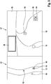
- FIG. 1 is a representation 1, which results directly from a measurement shown. To see is a road with two lanes 2,3, which are separated by lane boundary boundaries 10 respectively. On the lane 3 is the motor vehicle 4, which is also equipped with an embodiment of the invention, in particular also with sensor devices for carrying out the measurement. According to FIG. 1 Consequently, the driver assistance system has detected the two lanes 2, 3 with the associated lane markings 10 and also the objects 5, 6, 7.
- the objects 5 and 6 are each associated with movements, which are illustrated in the figure by the corresponding arrows 8, 9.
- the representation of the objects 5, 6, 7 as "X" is chosen arbitrarily. Depending on the type of object, other forms of representation could be used for this purpose.
- the objects 5, 6 are moving vehicles, while the object 7 may be, for example, a parking car located on the right-hand lane edge of the lane 3.
- FIG. 2 is a schematic display view to see 11, in which a correction of a measurement error is already taken into account, which was carried out by the embodiment of the invention.
- the motor vehicle 4 is to be seen in the same position on the lane 3 in the same way.
- the lane 2 and the associated lane markings 10 can be seen.
- a representation here is a display to see that for the driver momentarily unimportant objects, such as those that are located on the lane 2, are hidden.
- FIG. 1 is a schematic display view to see 11 in which a correction of a measurement error is already taken into account, which was carried out by the embodiment of the invention.
- FIG. 3 An example of a combined representation 12, 17 of several perspectives can be seen.
- An exemplary embodiment of a driver assistance system according to the invention could make this display representation available to a driver by means of a HUD.
- 12 shows a schematic view from a bird's eye view with a road 13, the motor vehicle 14 and two other objects 15, 16.
- the motor vehicle 14, which is equipped with the driver assistance system and the associated sensors, is characterized by a border marking 18.
- the object 15 is arbitrarily marked with a cross. This representation is chosen only for the sake of simplicity. Depending on the desired embodiment, for example, a color design could be preferred.
- the objects 15, 16 could, for example, vehicles but also any obstacles or, for example, animals refer to, which are located on or near the road.
- concrete representations of the objects or at least symbols which directly indicate the nature of the object could also be displayed here, eg an animal or vehicle symbol.
- a perspective view, similar to the driver's perspective, can be seen in the illustration 17.
- the motor vehicle 14 with the driver assistance system, the associated marking 18 of the motor vehicle 14, the object 15, which is located on the road 13 and the object 16, which is located on the left edge of the road can be seen.
- This can, for example, numerical information about the speeds of the vehicle 14, the objects 15, 16 and their relative velocities with each other or, for example, the distances of individual objects or vehicles 14, 15, 16 to each other.
- the driver assistance system can be designed so that some of this information is obtained from sensor data measured by sensor devices on the motor vehicle 14 and environmental coordinates received via a navigation system (eg for GPS, Galileo, etc.).
- a navigation system eg for GPS, Galileo, etc.
Description
Die Erfindung betrifft ein Fahrerassistenzsystem für Kraftfahrzeuge nach den Ansprüche.The invention relates to a driver assistance system for motor vehicles according to the claims.
Aus dem Stand der Technik sind einerseits handelsübliche Navigationssysteme und Einparkhilfen für Kraftfahrzeuge bekannt.On the one hand, commercially available navigation systems and parking aids for motor vehicles are known from the prior art.
Außerdem ist aus der Druckschrift
Aus der Druckschrift
Im Zusammenhang mit Head-Up-Displays ist aus der Druckschrift
Aus der
Aufgabe der Erfindung ist es, ein verbessertes Fahrerassistenzsystem für Kraftfahrzeuge vorzuschlagen, durch welches die Sicherheit im Straßenverkehr erhöht werden kann. Die Aufgabe wird ausgehend von einem Fahrerassistenzsystem für Kraftfahrzeuge der eingangs genannten Art durch die kennzeichnenden Merkmale des Anspruchs 1 gelöst.The object of the invention is to propose an improved driver assistance system for motor vehicles, by which the safety in road traffic can be increased. The object is achieved on the basis of a driver assistance system for motor vehicles of the type mentioned by the characterizing features of claim 1.
Durch die Merkmale der abhängigen Ansprüche sind vorteilhafte Ausführungsbeispiele und Weiterbildungen der Erfindung möglich.Due to the features of the dependent claims advantageous embodiments and modifications of the invention are possible.
Dementsprechend zeichnet sich ein erfindungsgemäßes Fahrerassistenzsystem für Kraftfahrzeuge mit wenigstens einer Sensorvorrichtung zur Erfassung und Positionsbestimmung von Objekten in der Umgebung des Kraftfahrzeugs, mit wenigstens einer Auswerteeinheit zur Verarbeitung und/oder Auswertung der Sensordaten der Sensorvorrichtung sowie Weiterleitung an eine Anzeigevorrichtung dadurch aus, dass die Auswerteeinheit Mittel zur Korrektur von Messfehlern umfasst, die eine Mehrzahl von Sensordaten wenigstens einer Sensorvorrichtung in Bezug auf ein Objekt heranziehen, um daraus eine Koordinate des Objekts zu bestimmen bzw. ein erfindungsgemäßes Fahrerassistenzsystem für Kraftfahrzeuge dadurch aus, dass die Auswerteeinheit Mittel zur Korrektur von Messfehlern umfasst, die Umgebungskoordinaten eines Navigationssystems zusammen mit Sensordaten wenigstens einer Sensorvorrichtung in Bezug auf ein Objekt heranziehen, um daraus eine Koordinate des Objekts zu bestimmen.Accordingly, an inventive driver assistance system for motor vehicles with at least one sensor device for detection and position determination of objects in the environment of the motor vehicle, with at least one evaluation unit for processing and / or evaluation of the sensor data of the sensor device and forwarding to a display device is characterized in that the evaluation unit means for correcting measurement errors, which use a plurality of sensor data of at least one sensor device with respect to an object in order to determine therefrom a coordinate of the object or an inventive driver assistance system for motor vehicles, characterized in that the evaluation unit comprises means for correcting measurement errors, the Environmental coordinates of a navigation system together with sensor data of at least one sensor device with respect to use an object to determine a coordinate of the object.
Sensorvorrichtungen, insbesondere auch solche zur Erfassung und Positionsbestimmung von Objekten in der Umgebung eines Beobachters, führen Messungen durch. Die somit erhaltenen Sensordaten und/oder Umgebungskoordinaten können mit einer Reihe von Messfehlern behaftet sein. Es kann sich dabei sowohl um systematische als auch statistische Messfehler handeln. Systematische Messfehler werden dabei in der Regel durch die Messmethodik selbst bedingt. Gerade im Zusammenhang mit Fahrerassistenzsystemen kann das Auftreten derartiger Messfehler den Fahrer erheblich verunsichern, unter Umständen sogar gefährden. Beispielsweise kann infolge von Messfehlern die Position eines Objektes wie beispielsweise eines Hindernisses oder eines weiteren, am Straßenverkehr beteiligten Kraftfahrzeugs falsch angezeigt werden. Die genannten Nachteile können dadurch behoben werden, dass die Auswerteeinheit Mittel zur Korrektur von Messfehlern umfasst, die Sensordaten wenigstens einer Sensorvorrichtung in Bezug auf ein Objekt bzw. zusätzlich die Umgebungskoordinaten eines Navigationssystems heranziehen, um daraus eine Koordinate des Objekts zu bestimmen. Es können z.B. auch neue Objektkoordinaten berechnet werden.
Der Fahrer ist nicht mehr darauf angewiesen, sich darauf zu verlassen, dass die verwendeten Sensordaten bzw. Umgebungskoordinaten nicht gerade zum aktuellen Zeitpunkt so genannte "Messausreißer" darstellen und somit eine unter Umständen von der Wirklichkeit sehr weit entfernte Angabe anzeigen.Sensor devices, in particular those for detecting and determining the position of objects in the surroundings of an observer, perform measurements. The sensor data and / or environment coordinates thus obtained can be subject to a number of measurement errors. These can be both systematic and statistical errors. Systematic measurement errors are usually determined by the measurement methodology itself. Especially in the context of driver assistance systems, the occurrence of such measurement errors can significantly unsettle the driver, under certain circumstances even jeopardize. For example, due to measurement errors, the position of an object such as an obstacle or another motor vehicle involved in road traffic can be displayed incorrectly. The mentioned disadvantages can be remedied by the fact that the evaluation unit comprises means for correcting measurement errors which use sensor data of at least one sensor device with respect to an object or additionally the environmental coordinates of a navigation system in order to determine therefrom a coordinate of the object. For example, new object coordinates can also be calculated.
The driver is no longer dependent on relying on the fact that the sensor data or environmental coordinates used do not currently constitute so-called "measurement outliers" at the current time and thus indicate an indication which may well be very far from reality.
Im Übrigen ist im Sinne der Erfindung unter Sensordaten ein allgemeiner Begriff für Daten bzw. Messwerte von Sensoren, z.B. Kameraeinheiten, fahrzeuginternen oder -externen Mess- und Bestimmungssystemen zu verstehen. Umgebungskoordinaten sind folglich im Sinne der Erfindung Sensordaten oder z.B. Daten eines Navigationssystems, die Auskunft über die Position von Objekten in der Umgebung des Kraftfahrzeugs liefern.Incidentally, for the purposes of the invention, sensor data is to be understood as a general term for data or measured values of sensors, for example camera units, vehicle-internal or external measuring and determination systems. environmental coordinate Consequently, for the purposes of the invention, sensor data or, for example, data of a navigation system provide information about the position of objects in the surroundings of the motor vehicle.
Grundsätzlich können sehr präzise Positionsbestimmungen über ein sogenanntes Navigationssystem gewonnen werden. Hierbei wird die Position des Fahrzeugs ermittelt und mit Informationen eines bestehenden Straßenkartensystems in Zusammenhang gebracht. Ein derartiges Navigationssystem kann sich daher hervorragend dazu eignen, entsprechende Umgebungskoordinaten an die Auswerteeinheit zu liefern und somit gleichfalls zu einer verbesserten Korrektur von Messfehlern beitragen.Basically, very precise position determinations can be obtained via a so-called navigation system. Here, the position of the vehicle is determined and associated with information of an existing road map system. Such a navigation system can therefore be eminently suitable for supplying corresponding environmental coordinates to the evaluation unit and thus also contribute to an improved correction of measurement errors.
Des Weiteren kann bei einem erfindungsgemäßen Fahrerassistenzsystem die Auswerteeinheit Mittel zur Korrektur von Messfehlern umfassen, die den Sensordaten einer Sensorvorrichtung weitere Sensordaten einer anderen Sensorvorrichtung zuordnet werden und daraus weitere Daten erzeugt. Es können also beispielsweise die Sensordaten einer Sensorvorrichtung mit denen einer weiteren Sensorvorrichtung verglichen werden, so dass daraus geschlossen werden kann, ob Sensordaten bei einer Messung verlässlich bzw. plausibel sind oder nicht. Beispielsweise könnte einem Fahrzeug, dessen Koordinaten ermittelt wurden, mit Hilfe von Umgebungskoordinaten eines Navigationssystem eine Fahrspur zugeordnet werden, wobei das Navigationssystem das Fahrzeug z.B. als "Geisterfahrer" erkennt. Beispielsweise könnte dem Fahrzeug auch eine Position außerhalb jeglicher Fahrspur zugeordnet werden, sodass es sich entweder um eine außergewöhnliche Situation, z.B. einen Unfall, oder eventuell auch eine unplausible Zuordnung handelt.Furthermore, in a driver assistance system according to the invention, the evaluation unit may comprise means for correcting measurement errors which associate the sensor data of a sensor device with further sensor data of another sensor device and generates further data therefrom. Thus, for example, the sensor data of a sensor device can be compared with those of a further sensor device, so that it can be concluded from whether sensor data are reliable or plausible during a measurement or not. For example, a vehicle whose coordinates have been determined could be assigned a lane by means of environmental coordinates of a navigation system, the navigation system determining the vehicle, e.g. recognizes as a "ghost driver". For example, the vehicle could also be assigned a position outside of any lane so that it is either an exceptional situation, e.g. an accident, or possibly also an implausible assignment.
Bei einer vorteilhaften Ausführungsform der Erfindung umfasst die Auswerteeinheit Mittel zur Korrektur von Messfehlern, welche den Koordinaten des Objekts Sensordaten und/oder Umgebungskoordinaten eines Navigationssystems zuordnet und hieraus weitere Daten erzeugt. Dies bedeutet, dass beispielsweise die von der Auswerteeinheit ermittelten Koordinaten eines Objekts mit Sensordaten oder Umgebungskoordinaten eines Navigationssystems in Verbindung gebracht werden können, um somit weitere Informationen zu erhalten.In an advantageous embodiment of the invention, the evaluation unit comprises means for correcting measurement errors, which assigns sensor data and / or environmental coordinates of a navigation system to the coordinates of the object and generates further data therefrom. This means that, for example, the coordinates of an object determined by the evaluation unit can be associated with sensor data or environmental coordinates of a navigation system in order thus to obtain further information.
Bei einem besonders bevorzugten Ausführungsbeispiel der Erfindung umfasst die Auswerteeinheit eine statistische Mittelungseinheit zur Mittelung von Sensordaten und/oder Umgebungskoordinaten. Eine statistische Mittelung ist eine vergleichsweise einfache und zweckmäßige Maßnahme, um Korrekturen von Messfehlern vorzunehmen. Insbesondere statistische Fehler können so in der Regel korrigiert werden. Besonders vorteilhaft kann eine Mittelung jedoch auch dann erfolgen, wenn zur Korrektur insbesondere von systematischen Fehlern nicht nur über verschiedene Sensordaten bzw. Umgebungskoordinaten gemittelt wird, die einem einzelnen Sensor zugeordnet werden können, sondern auch über solche Messwerte gemittelt wird, die von wenigstens zwei verschiedenen Sensoren stammen. Außerdem ist es möglich, weitere Erfahrungswerte mit einzubringen, beispielsweise können bei einer solchen Mittelung auch unterschiedliche Sensordaten und/oder Umgebungskoordinaten mit speziellen Gewichtungen versehen werden. Denkbar ist beispielsweise, dass einem speziellen Sensor eine relativ hohe Verlässlichkeit zugebilligt werden kann. Die Daten dieses Sensors könnten daher z.B. bei einer Mittelung stärker gewichtet werden als andere Sensordaten bzw. Umgebungskoordinaten.In a particularly preferred embodiment of the invention, the evaluation unit comprises a statistical averaging unit for averaging sensor data and / or environmental coordinates. A statistical averaging is a comparatively simple and expedient measure for making corrections of measurement errors. In particular statistical errors can be corrected as a rule. However, an averaging can also take place particularly advantageously if it is not only averaged over different sensor data or environmental coordinates that can be assigned to a single sensor, but also averaged over those measured values from at least two different sensors come. In addition, it is possible to introduce further empirical values, for example, different averaging data and / or environmental coordinates can also be provided with special weightings in the case of such averaging. It is conceivable, for example, that a special sensor can be granted relatively high reliability. The data of this sensor could therefore be e.g. be weighted more heavily in an averaging than other sensor data or environmental coordinates.
Insbesondere ist dafür notwendig, dass bei einer bevorzugten Weiterbildung der Erfindung wenigstens eine weitere Sensorvorrichtung und/oder eine Kamera zur Lieferung von Sensordaten und/oder Umgebungskoordinaten an die Auswerteeinheit vorgesehen ist/sind. Wie bereits erwähnt, kann es unter anderem zur Korrektur systematischer Fehler vorteilhaft sein, die Daten bzw. Umgebungskoordinaten mehrerer verschiedener Sensorvorrichtungen, eventuell auch von unterschiedlichen Bautypen, mit einzubeziehen. Einerseits sind dabei Sensorvorrichtungen zur Erfassung bzw. Positionsbestimmung von Objekten der Umgebung des Kraftfahrzeugs unter anderem gemeint. Andererseits ist es auch denkbar, andersartige Sensorvorrichtungen zusätzlich einzusetzen, beispielsweise solche Sensoren, welche Informationen über die Sichtverhältnisse liefern, z.B. ob die Sicht gerade durch Nebel oder Regen beeinflusst wird. Diese Informationen könnten beispielsweise unter anderem zu einer Anpassung der Gewichtung bei der Mittelung Verwendung finden.In particular, it is necessary that, in a preferred development of the invention, at least one further sensor device and / or a camera for the delivery of Sensor data and / or environmental coordinates is provided to the evaluation unit / are. As already mentioned, among other things it can be advantageous for the correction of systematic errors to include the data or environmental coordinates of a plurality of different sensor devices, possibly also of different types of construction. On the one hand, sensor devices for detecting or determining the position of objects of the surroundings of the motor vehicle are meant among others. On the other hand, it is also conceivable to use other types of sensor devices in addition, for example, those sensors which provide information about the visibility, for example, whether the view is being influenced by fog or rain. This information could be used inter alia to adjust the weighting in averaging.
Als Sensorvorrichtung ist beispielsweise auch eine Kamera denkbar. Sowohl mittels einer derartigen Kamera als auch infolge einer Durchführung mehrerer Messungen hintereinander durch wenigstens eine Sensorvorrichtung ist es bei Ausführungsbeispielen der Erfindung möglich, auch bewegte Objekte darzustellen.As a sensor device, for example, a camera is conceivable. Both by means of such a camera and as a result of carrying out several measurements in succession by at least one sensor device, it is possible in embodiments of the invention to also represent moving objects.
Weitere denkbare Umfeldsensoren sind beispielsweise RADAR, LIDAR, insbesondere zur Längsführung des Fahrzeugs, insbesondere im Zusammenhang mit ACC-Systemen (Englisch: Active/Adaptive Cruise Control, Abstands- und Geschwindigkeitsregler), Umfeldsensoren für Sicherheitsanwendungen, z.B. PSS (Prodecitve safety system, Fahrzeugbremssystem), weitere Umfeldsensoren z.B. für Parksysteme wie Parkpiloten, erweiterte Parkpilotsysteme oder sogenannte "Backing-aid-Syteme", aber auch Umfeldsensoren für Überwachungsfunktionen des Fahrzeugrück- bzw. Fahrzeugseitenraums (LCA). Denkbar ist auch die Verwendung von 3D-Darstellungen.Other conceivable environment sensors are, for example, RADAR, LIDAR, in particular for longitudinal guidance of the vehicle, in particular in connection with ACC systems (English: Active / Adaptive Cruise Control, distance and speed controller), environment sensors for safety applications, eg PSS (Prodecitve safety system, vehicle brake system) Further environment sensors eg for parking systems such as park pilots, extended park pilot systems or so-called "backing aid systems", but also environment sensors for monitoring functions of the vehicle rear or vehicle side space (LCA). Also conceivable is the use of 3D representations.
Neben der bloßen Erkennung von Objekten wie anderen Fahrzeugen oder potentiellen Verkehrshindernissen kann es jedoch von besonderem Vorteil sein, bei einer bevorzugten Ausführungsform der Erfindung eine Sensorvorrichtung zur Erkennung einer Fahrspur vorzusehen. Für den Fahrer kann es durchaus hilfreich sein, nicht nur die Koordinaten eines bestimmten Objektes zu kennen oder den Abstand, den dieses Objekt zu seinem Fahrzeug besitzt, sondern z.B. auch, welche Position ein entsprechendes Objekt in Bezug auf seine Fahrspur hat. Besonders wichtige Beispiele hierfür sind etwa ein Tier, das sich unmittelbar am Fahrbahnrand befindet, ein Geisterfahrer oder ein anderes, entgegenkommendes Fahrzeug, das beispielsweise ein gefährliches Überholmanöver durchführt. In diesem Kontext existieren zahlreiche Ausgestaltungen von Ausführungsbeispielen der Erfindung, beispielsweise eine Bestimmung des Abstands zum Fahrbahnrand, welche etwa bei der Durchfahrt durch Baustellen korrigiert werden sollte oder eine Abstandsbestimmung zu parkenden Fahrzeugen.However, in addition to the mere detection of objects such as other vehicles or potential traffic obstacles, it may be of particular advantage to provide a sensor device for detecting a traffic lane in a preferred embodiment of the invention. For the driver, it may be helpful to know not only the coordinates of a particular object or the distance this object has to its vehicle, but e.g. Also, what position has a corresponding object in relation to its lane. Particularly important examples of this are, for example, an animal that is located directly on the roadside, a ghost driver or another, oncoming vehicle, for example, performs a dangerous overtaking maneuver. In this context, there are numerous embodiments of embodiments of the invention, for example, a determination of the distance to the lane edge, which should be corrected when passing through construction sites, or a distance determination to parked vehicles.
In einigen Fällen reicht es jedoch nicht aus, allein Angaben über die Position zu kennen. Vielmehr ist es außerdem notwendig, Informationen über die Relativgeschwindigkeiten zwischen dem Kraftfahrzeug und anderen Objekten zu kennen oder zumindest einschätzen zu können. Insbesondere ist hierbei an Situationen zu denken, wenn das Kraftfahrzeug z.B. ein Überholmanöver durchführt oder sich Kraftfahrzeugen nähert, die in einem Stau stehen. Einerseits ist es denkbar, im Sinne der bereits oben genannten Ausführungsbeispiele, spezielle Geschwindigkeitssensoren bei einer Weiterbildung der Erfindung vorzusehen. Es ist aber auch denkbar, bei einer Ausführungsform der Erfindung die Auswerteeinheit so auszulegen, dass sie zur Bestimmung der Relativgeschwindigkeiten zwischen dem Kraftfahrzeug und anderen Objekten geeignet ist.However, in some cases it is not enough to know the position alone. Rather, it is also necessary to know or at least be able to estimate information about the relative speeds between the motor vehicle and other objects. In particular, in this case is to be considered situations when the motor vehicle, for example, performs an overtaking maneuver or approaching motor vehicles that are in a traffic jam. On the one hand, it is conceivable, within the meaning of the embodiments already mentioned above, to provide special speed sensors in a development of the invention. However, it is also conceivable, in one embodiment of the invention, to design the evaluation unit such that it is suitable for determining the relative speeds between the motor vehicle and other objects.
Denkbar ist es weiterhin, dem Fahrer während der Fahrt gewisse Entscheidungshilfen und Zusatzinformationen in Form von Gefährdungsgrößen an die Hand zu geben. Beispielsweise kann aus der Relativgeschwindigkeit zwischen dem Kraftfahrzeug und einem Objekt bzw. aus der Position eines Objekts eine derartige Gefährdungsgröße bestimmt werden, deren Wert der Einstufung des Gefährdungspotentials in eine vorgegebene Skala erlaubt. Somit ist es vorteilhaft, bei einer Weiterbildung der Erfindung die Auswerteeinheit dazu auszulegen, dass eines der Objekte mit einer Gefährdungsgröße unter anderem aus der Position und/oder der Relativgeschwindigkeit zwischen dem Fahrzeug und dem Objekt verknüpfbar ist.It is also conceivable to give the driver while driving certain decision-making aids and additional information in the form of risk parameters at hand. For example, from the relative speed between the motor vehicle and an object or from the position of an object, such a risk variable can be determined whose value allows the risk potential to be classified into a predetermined scale. Thus, it is advantageous in a further development of the invention to design the evaluation unit in such a way that one of the objects can be linked to a hazard quantity, inter alia, from the position and / or the relative speed between the vehicle and the object.
Unter anderem ist es in diesem Kontext vorteilhaft, bei einer Ausführungsform der Erfindung, Warnvorrichtungen vorzusehen. Somit können z.B. entsprechende Gefährdungsgrößen nicht nur bestimmt werden sondern lösen auch Warnhinweise für den Fahrer bzw. den Benutzer aus. Dabei kann es sich um Einfärbungen spezieller Objekte, z.B. in Rot, aber auch um akustische Warnhinweise, Blinkanzeigen oder Ähnliches handeln. Auch hierdurch kann die Sicherheit für den Fahrer noch einmal erheblich verbessert werden.Among other things, it is advantageous in this context to provide warning devices in one embodiment of the invention. Thus, e.g. corresponding hazard parameters are not only determined but also trigger warnings for the driver or the user. These may be colorations of specific objects, e.g. in red, but also to audible warnings, flashing indicators or the like act. This also allows the safety for the driver can be significantly improved again.
Vorteilhafterweise ist bei einem Ausführungsbeispiel der Erfindung eine Anzeigevorrichtung vorhanden, in besonders bevorzugter Weise ein HUD. Derartige Projektionsanzeigevorrichtungen existieren bereits als etablierte Anzeigesysteme in Kraftfahrzeugen, Flugzeugen usw. Denkbar sind hier des Weiteren alle Ausgestaltungsformen von HUDs wie z.B. i-HUDs (Inverse HUD), welche über ein Fahrerbeobachtungssystem verfügen, HUDs zur kontaktanalogen Darstellung und vieles mehr. Die Verwendung bereits etablierter Anzeigevorrichtungen kann auch einen entscheidenden Kostenvorteil bewirken.Advantageously, in one embodiment of the invention, a display device is present, in a particularly preferred manner a HUD. Such projection display devices already exist as established display systems in motor vehicles, aircraft, etc. Furthermore, all embodiments of HUDs, such as i-HUDs (inverse HUD), which have a driver observation system, HUDs for contact-analogue display and much more are conceivable here. The use of already established display devices can also bring a significant cost advantage.
Denkbar sind aber ohne Weiteres auch andere Anzeigemöglichkeiten, welche in vorteilhafter Weise das Fahrerassistenzsystem an die individuellen Wünsche des Benutzers bzw. Fahrers anpassbar macht. Bei einer bevorzugten Weiterbildung der Erfindung kann somit die Anzeigevorrichtung als PDA (Englisch: personal digital assistant) bzw. als Navigationsanzeige eines Navigationssystems bzw. als Kopfstützendisplay, welches als Anzeigevorrichtung in die Kopfstützen eines Fahrzeugs, insbesondere für die Formpassagiere integriert ist, ausgebildet sein. Es sind also verschiedene Varianten von externen Anzeigevorrichtungen als auch von fahrzeuginternen Anzeigevorrichtungen zur Benutzung möglich. Als mögliche Vorteile sollte hier neben dem Kostenaspekt insbesondere auch auf die möglichen Synergien einzelner Assistenzsysteme für das Fahrzeug aber auch einzelner Computersysteme (z.B. PDA) usw. abgestellt werden.Conceivable, however, are without further ado other display options, which advantageously makes the driver assistance system adaptable to the individual wishes of the user or driver. In a preferred embodiment of the invention, thus, the display device as PDA (English: personal digital assistant) or as a navigation display of a navigation system or as a headrest display, which is integrated as a display device in the headrests of a vehicle, especially for the form of passengers. Thus, different variants of external display devices as well as in-vehicle display devices for use are possible. In addition to the cost aspect, the possible advantages here should also be focused on the possible synergies of individual assistance systems for the vehicle, but also individual computer systems (for example, PDAs), etc.
Eine gängige Art und Weise der Anzeigedarstellung ist die Integration von Anzeigeinstrumenten im Kombi-Instrument des Kraftfahrzeugs. Daher ist bei einem vorteilhaften Ausführungsbeispiel der Erfindung die Anzeigevorrichtung im Kombiinstrument des Kraftfahrzeugs integriert.A common way of display display is the integration of display instruments in the instrument cluster of the motor vehicle. Therefore, in an advantageous embodiment of the invention, the display device is integrated in the instrument cluster of the motor vehicle.
Bei einer besonders bevorzugten Weiterbildung der Erfindung ist das Fahrerassistenzsystem in Fahrzeuge mit bereits vorhandenen Sensorvorrichtungen und/oder Anzeigevorrichtungen und/oder Navigationssystemen integrierbar. Viele Fahrzeuge verfügen bereits über Anzeigevorrichtungen wie HUDs, über Navigationssysteme oder einzelne Sensorvorrichtungen. Müssten zur Verwendung eines erfindungsgemäßen Fahrerassistenzsystems bzw. einer Ausführungsform der Erfindung alle diese Vorrichtungen aus Kompatibilitätsgründen erneuert werden, wäre die Anschaffung eines solchen Fahrerassistenzsystems mit einem erheblichen Kostennachteil verbunden. Ein integrierbar gesaltetes Fahrerassistenzsystem jedoch erlaubt es, zumindest einige dieser Vorrichtungen zu nutzen. Außer dem Kostenvorteil muss sich der Fahrer unter Umständen auch nicht mehr auf völlig neue Apparaturen in seinem Kraftfahrzeug einstellen und gewöhnen. Z.B. könnte die gleiche HUD in gewohnter Weise weiter verwendet werden, dem Fahrer jedoch zusätzliche Informationen bereit stellen und somit den Fahrkomfort entscheidend verbessern und auch zur erhöhten Sicherheit im Straßenverkehr beitragen.In a particularly preferred development of the invention, the driver assistance system can be integrated into vehicles with existing sensor devices and / or display devices and / or navigation systems. Many vehicles already have display devices such as HUDs, navigation systems or individual sensor devices. If all of these devices had to be renewed for compatibility reasons for the purpose of using a driver assistance system according to the invention or an embodiment of the invention, the acquisition of such a driver assistance system would entail a considerable cost disadvantage. An integrable However, a switched driver assistance system makes it possible to use at least some of these devices. In addition to the cost advantage, the driver may no longer have to adjust and get used to completely new equipment in his motor vehicle. For example, the same HUD could continue to be used in the usual way, but provide the driver additional information and thus significantly improve ride comfort and also contribute to increased safety on the road.
Je nach dem, welche Fahrsituation gerade vorliegt oder welche Anzeigedarstellung vom Fahrer in individueller Weise bevorzugt wird, kann z.B. die Auswerteeinheit so ausgelegt sein, dass sie die Sensordaten, Umgebungskoordinaten bzw. Gefährdungsgrößen usw. in der entsprechenden Weise aufbereitet und ausgeben lässt. Ein Ausführungsbeispiel der Erfindung umfasst vorteilhafterweise eine Auswerteeinheit, die zur Erzeugung einer perspektivischen Darstellung ausgelegt ist. Diese Darstellungsweise bietet den Vorteil, dass der Fahrer etwa aus seiner Sicht oder von einem scheinbar etwas erhöhten Standpunkt, Objekte, Fahrbahnen usw. in der Umgebung des Fahrzeugs wahrnehmen kann.Depending on which driving situation is currently present or which display presentation is individually preferred by the driver, e.g. the evaluation unit can be designed so that it can process and output the sensor data, environmental coordinates or hazard variables etc. in the corresponding manner. An embodiment of the invention advantageously comprises an evaluation unit, which is designed to produce a perspective view. This mode of presentation offers the advantage that the driver can perceive, for example from his point of view or from an apparently somewhat elevated position, objects, roadways etc. in the surroundings of the vehicle.
Erfindungsgemäß ist bei einer Ausführungsform der Erfindung die Auswerteeinheit zur Erstellung einer Darstellung wenigstens eines Teils der Umgebung auf der Vogelperspektive ausgelegt. Dies ist insbesondere dann wünschenswert, wenn beispielsweise Objekte, welche um das Kraftfahrzeug herum stehen können, von Bedeutung sind und nicht nur beispielsweise der Blick in Fahrtrichtung. Eine typische Situation ist das Rückwärtseinparken.According to the invention, in one embodiment of the invention, the evaluation unit is designed to produce a representation of at least part of the surroundings on the bird's-eye view. This is particularly desirable if, for example, objects that can stand around the motor vehicle, are important and not just, for example, the view in the direction of travel. A typical situation is reverse parking.
Entsteht für den Fahrer bzw. für das Kraftfahrzeug eine gefährliche Situation, indem beispielsweise einzelne Objekte in bedenklicher Nähe zum Kraftfahrzeug auftauchen, ist es wünschenswert, einen entsprechenden Hinweis an den Fahrer auszugeben. Eine bevorzugte Ausführungsform der Erfindung umfasst dabei eine Auswerteeinheit, die zur Zuordnung von Gefährdungsgrößen und Farben für die Darstellung mittels der Anzeigevorrichtung ausgelegt ist.If a dangerous situation arises for the driver or for the motor vehicle, for example if individual objects emerge in a dangerously close proximity to the motor vehicle, it is desirable to issue a corresponding note to the driver. In this case, a preferred embodiment of the invention comprises an evaluation unit which is designed for the assignment of risk variables and colors for the display by means of the display device.
Andere Größen wie beispielsweise die Geschwindigkeit eines anderen Objektes, die Relativgeschwindigkeit des Objektes in Bezug auf die des Kraftfahrzeugs oder beispielsweise einzelne Abstände, können auch konkret angezeigt und/oder einzelnen Objekten zugeordnet werden. Bei einem vorteilhaften Ausführungsbeispiel der Erfindung ist daher die Auswerteeinheit zur Ausgabe und Darstellung alphanumerischer Größen ausgelegt. Generell ist es besonders vorteilhaft, wenn entweder der Fahrer die Darstellungsweise seinen Wünschen entsprechend anpassen kann oder diese entsprechend den einzelnen Situationen bereits angepasst sind.Other variables such as, for example, the speed of another object, the relative speed of the object with respect to that of the motor vehicle or, for example, individual distances, can also be indicated concretely and / or assigned to individual objects. In an advantageous embodiment of the invention, therefore, the evaluation unit is designed for output and display of alphanumeric variables. In general, it is particularly advantageous if either the driver can customize the presentation according to his wishes or these are already adapted according to the individual situations.
Außerdem zeichnet sich dementsprechend das Verfahren zur Feststellung einer Objektposition und Optimierung von positionsbezogenen Objektanzeigen gemäß der Erfindung dadurch aus, dass eine Korrektur von Messfehlern mittels eines Fahrerassistenzsystems nach Anspruch 1, 2 oder 3 bzw. einem der abhängigen Ansprüche erfolgt. Durch ein derartiges Verfahren können dem Fahrer plausiblere und wirklichkeitsgetreuere Auskünfte zur Verfügung gestellt werden und somit dem Fahrer eine wertvolle Hilfestellung geben, um den Straßenverkehr sicherer zu gestalten.In addition, the method for determining an object position and optimizing position-related object displays according to the invention is accordingly characterized in that a correction of measurement errors takes place by means of a driver assistance system according to
Ausführungsbeispiele der Erfindung sind in den Zeichnungen dargestellt und werden nachstehend unter Angabe weiterer Vorteile und Einzelheiten näher erläutert. Im Einzelnen zeigen:
- Figur 1
- eine schematische Darstellung einer Umgebungsmessung mit einer Straße mit zwei Fahrspuren sowie verschiedenen Objekten in der Vogelperspektive,
Figur 2- eine schematische Anzeigedarstellung einer Straße mit zwei Fahrspuren aus der Vogelperspektive mit einer Positionskorrektur eines Objekts sowie
Figur 3- eine schematische Kombinationsdarstellung von Umgebungsanzeigen in verschiedenen Perspektiven.
- FIG. 1
- a schematic representation of an environmental measurement with a road with two lanes and various objects in a bird's eye view,
- FIG. 2
- a schematic display representation of a road with two lanes from a bird's eye view with a position correction of an object and
- FIG. 3
- a schematic combination of environmental displays in different perspectives.
In
In
In
Claims (13)
- Driver assistance system for motor vehicles (4, 14), comprising:- at least one sensor apparatus for detecting and determining the position of objects (5, 6, 7, 10, 15, 16) in the environment of the motor vehicle (4, 14),- at least one evaluation unit for processing and/or evaluating the sensor data from the sensor apparatus and for forwarding said data to a display apparatus, the evaluation unit comprising means for correcting measurement errors, characterized in that the means use the environmental coordinates from a navigation system, together with sensor data from at least one sensor apparatus, with respect to an object in order to determine a coordinate of the object therefrom, characterized in that the evaluation unit assigns sensor data and/or environmental coordinates from the navigation system to the coordinates of the object and generates further data therefrom, and in that the evaluation unit is designed to create a representation (11, 12) of at least one part of the environment from a bird's eye view.
- Driver assistance system according to one of the abovementioned claims, characterized in that the evaluation unit comprises a statistical averaging unit for averaging sensor data and/or environmental coordinates.
- Driver assistance system according to one of the abovementioned claims, characterized in that at least one further sensor apparatus and/or a camera is/are provided for the purpose of providing the evaluation unit with sensor data and/or environmental coordinates.
- Driver assistance system according to one of the abovementioned claims, characterized in that a sensor apparatus is designed to detect a lane.
- Driver assistance system according to one of the abovementioned claims, characterized in that the evaluation unit is designed to determine the relative speeds between the motor vehicle and the objects (5, 6, 7, 10, 15, 16).
- Driver assistance system according to one of the abovementioned claims, characterized in that the evaluation unit is designed to link one of the objects (5, 6, 7, 10, 15, 16) to a hazard variable, inter alia from the position and/or the relative speed between the motor vehicle and the object (5, 6, 7, 10, 15, 16).
- Driver assistance system according to one of the abovementioned claims, characterized in that warning apparatuses are provided.
- Driver assistance system according to one of the abovementioned claims, characterized in that a display apparatus, in particular a head-up display, is provided.
- Driver assistance system according to one of the abovementioned claims, characterized in that the display apparatus is in the form of a PDA and/or a navigation display and/or a headrest display.
- Driver assistance system according to one of the abovementioned claims, characterized in that the display apparatus is integrated in the combination instrument of the motor vehicle (4, 14).
- Driver assistance system according to one of the abovementioned claims, characterized in that the driver assistance system can be integrated in vehicles having sensor apparatuses and/or display apparatuses and/or navigation systems which are already provided.
- Driver assistance system according to one of the abovementioned claims, characterized in that the evaluation unit is designed to assign hazard variables and colours for the representation by means of the display apparatus.
- Driver assistance system according to one of the abovementioned claims, characterized in that the evaluation unit is designed to output and represent (20) alphanumeric variables.
Applications Claiming Priority (1)
| Application Number | Priority Date | Filing Date | Title |
|---|---|---|---|
| DE102008042825A DE102008042825A1 (en) | 2008-10-14 | 2008-10-14 | Driver assistance system for motor vehicles |
Publications (3)
| Publication Number | Publication Date |
|---|---|
| EP2178063A2 EP2178063A2 (en) | 2010-04-21 |
| EP2178063A3 EP2178063A3 (en) | 2011-01-19 |
| EP2178063B1 true EP2178063B1 (en) | 2017-06-07 |
Family
ID=41582187
Family Applications (1)
| Application Number | Title | Priority Date | Filing Date |
|---|---|---|---|
| EP09168064.5A Active EP2178063B1 (en) | 2008-10-14 | 2009-08-18 | Driver assistance system for motor vehicles |
Country Status (3)
| Country | Link |
|---|---|
| EP (1) | EP2178063B1 (en) |
| CN (1) | CN101727759B (en) |
| DE (1) | DE102008042825A1 (en) |
Families Citing this family (16)
| Publication number | Priority date | Publication date | Assignee | Title |
|---|---|---|---|---|
| DE102010052128A1 (en) | 2010-11-22 | 2012-05-24 | GM Global Technology Operations LLC | Method for operating a motor vehicle and motor vehicle |
| DE102010062350A1 (en) * | 2010-12-02 | 2012-06-06 | Robert Bosch Gmbh | Method for assisting a driver of a motor vehicle |
| DE102011005368A1 (en) | 2011-03-10 | 2012-09-13 | Robert Bosch Gmbh | Driver assistance system for vehicle, particularly designed as assistance system for shunters or for parking vehicle, has video camera, by which video image of surrounding area of vehicle is recorded with objects |
| JP5316572B2 (en) * | 2011-03-28 | 2013-10-16 | トヨタ自動車株式会社 | Object recognition device |
| DE102011076763A1 (en) | 2011-05-31 | 2012-12-06 | Robert Bosch Gmbh | Driver assistance system and method for operating a driver assistance system |
| DE102012201982A1 (en) * | 2012-02-10 | 2013-08-14 | Robert Bosch Gmbh | Method and device for community-based navigation |
| CN104050829A (en) * | 2013-03-14 | 2014-09-17 | 联想(北京)有限公司 | Information processing method and apparatus |
| DE102013009856B4 (en) * | 2013-06-13 | 2023-11-02 | Audi Ag | Determining the position of a stationary traffic object using a central server arrangement |
| CN103337179B (en) * | 2013-07-01 | 2015-04-15 | 深圳市凌启电子有限公司 | System and method for reminding bad driving behaviors |
| CN104424804B (en) * | 2013-09-10 | 2016-08-10 | 上海弘视通信技术有限公司 | Single radar multilane Intelligent speed-measuring method and system thereof |
| CN103500514A (en) * | 2013-09-11 | 2014-01-08 | 奇瑞汽车股份有限公司 | Vehicle speed early-warning method, device and system in special road section |
| CN104867327B (en) * | 2014-02-21 | 2017-05-03 | 中国移动通信集团公司 | Driving safety monitoring method and device |
| DE102014220324A1 (en) * | 2014-10-07 | 2016-06-30 | Continental Automotive Gmbh | Head-up display for monitoring a traffic area |
| US9770987B1 (en) * | 2016-08-18 | 2017-09-26 | Volkswagen Ag | Safety visualizations for navigation interface |
| US10239451B1 (en) * | 2017-09-05 | 2019-03-26 | GM Global Technology Operations LLC | Systems and methods for providing relative lane assignment of objects at distances from the vehicle |
| DE102017220268B4 (en) | 2017-11-14 | 2024-03-21 | Volkswagen Aktiengesellschaft | Detection and visualization of system uncertainty when displaying augmented image content in head-up displays |
Family Cites Families (9)
| Publication number | Priority date | Publication date | Assignee | Title |
|---|---|---|---|---|
| CN1137138A (en) * | 1995-05-30 | 1996-12-04 | 谭顺成 | Omnibearing directional monitoring system |
| US7085637B2 (en) * | 1997-10-22 | 2006-08-01 | Intelligent Technologies International, Inc. | Method and system for controlling a vehicle |
| DE19847611C2 (en) | 1998-10-15 | 2003-06-18 | Volkswagen Ag | Process for the integrated representation of the parameters of a combined ADR / GRA system |
| JP4354085B2 (en) | 2000-05-09 | 2009-10-28 | 本田技研工業株式会社 | Head-up display device for vehicle |
| JP4615139B2 (en) * | 2001-03-30 | 2011-01-19 | 本田技研工業株式会社 | Vehicle periphery monitoring device |
| JP4055656B2 (en) * | 2003-05-30 | 2008-03-05 | トヨタ自動車株式会社 | Collision prediction device |
| JP4274111B2 (en) | 2004-12-02 | 2009-06-03 | 株式会社デンソー | Proper inter-vehicle distance display control device |
| US7864032B2 (en) * | 2005-10-06 | 2011-01-04 | Fuji Jukogyo Kabushiki Kaisha | Collision determination device and vehicle behavior control device |
| US8098889B2 (en) * | 2007-01-18 | 2012-01-17 | Siemens Corporation | System and method for vehicle detection and tracking |
-
2008
- 2008-10-14 DE DE102008042825A patent/DE102008042825A1/en not_active Withdrawn
-
2009
- 2009-08-18 EP EP09168064.5A patent/EP2178063B1/en active Active
- 2009-09-30 CN CN200910204006.XA patent/CN101727759B/en active Active
Non-Patent Citations (1)
| Title |
|---|
| None * |
Also Published As
| Publication number | Publication date |
|---|---|
| DE102008042825A1 (en) | 2010-04-15 |
| CN101727759A (en) | 2010-06-09 |
| CN101727759B (en) | 2015-11-25 |
| EP2178063A2 (en) | 2010-04-21 |
| EP2178063A3 (en) | 2011-01-19 |
Similar Documents
| Publication | Publication Date | Title |
|---|---|---|
| EP2178063B1 (en) | Driver assistance system for motor vehicles | |
| EP3183152B1 (en) | Method for warning a driver of a vehicle of the presence of an object in the surroundings, driver assistance system and motor vehicle | |
| EP3386825B1 (en) | Method for identifying a possible collision between a motor vehicle and an object by taking into account a spatial uncertainty, control device, driver assistance system and motor vehicle | |
| DE102011083039B4 (en) | Device and method for operating a vehicle | |
| DE102010052128A1 (en) | Method for operating a motor vehicle and motor vehicle | |
| DE102012005272A1 (en) | Method for determining risk probability of situation between two vehicles, for issuing different driver warnings, involves determining space for maneuvering between vehicles for determining risk probability, based on size of each space | |
| DE102016000209A1 (en) | A control system and method for determining a pavement irregularity | |
| WO2020173775A1 (en) | Method for operating a driver information system in an ego-vehicle and driver information system | |
| EP3569465A1 (en) | System and method for providing an automation function for a vehicle | |
| DE202014003224U1 (en) | Driver assistance system for warning a driver of a collision with another road user | |
| DE102016000185A1 (en) | Control system and method for determining a lane of a subsequent motor vehicle | |
| DE102019202581A1 (en) | Method for operating a driver information system in an ego vehicle and driver information system | |
| DE102017212432A1 (en) | Method and device for operating a driver assistance system of a motor vehicle and driver assistance systems | |
| WO2016177450A1 (en) | Superimposing an object or occurrence in a motor vehicle environment | |
| DE102018219665A1 (en) | Method and control unit for operating an autonomous vehicle | |
| DE102018004573A1 (en) | Method for informing a driver of a vehicle | |
| DE102014105374B4 (en) | Driver assistance system | |
| EP1967821A1 (en) | Assistance system for the driver of a vehicle, in particular of a motor vehicle for road traffic | |
| DE102013008946A1 (en) | Device and method for detecting a critical driving situation of a vehicle | |
| DE102015006640A1 (en) | Presentation of augmented navigation elements by a head-up display system | |
| DE102011077975A1 (en) | Driver assistance system for motor vehicle, has narrow place assistance system that is provided with control module, and distance-related vehicle speed control system that is provided with another control module | |
| DE102017212222B3 (en) | Method for operating a display device of a motor vehicle, driver assistance device, and motor vehicle | |
| DE102008018512B4 (en) | Driver assistance system and associated procedure | |
| DE102014214507A1 (en) | Method for creating an environment model of a vehicle | |
| DE102014214505A1 (en) | Method for creating an environment model of a vehicle |
Legal Events
| Date | Code | Title | Description |
|---|---|---|---|
| PUAI | Public reference made under article 153(3) epc to a published international application that has entered the european phase |
Free format text: ORIGINAL CODE: 0009012 |
|
| AK | Designated contracting states |
Kind code of ref document: A2 Designated state(s): AT BE BG CH CY CZ DE DK EE ES FI FR GB GR HR HU IE IS IT LI LT LU LV MC MK MT NL NO PL PT RO SE SI SK SM TR |
|
| AX | Request for extension of the european patent |
Extension state: AL BA RS |
|
| PUAL | Search report despatched |
Free format text: ORIGINAL CODE: 0009013 |
|
| AK | Designated contracting states |
Kind code of ref document: A3 Designated state(s): AT BE BG CH CY CZ DE DK EE ES FI FR GB GR HR HU IE IS IT LI LT LU LV MC MK MT NL NO PL PT RO SE SI SK SM TR |
|
| AX | Request for extension of the european patent |
Extension state: AL BA RS |
|
| RIC1 | Information provided on ipc code assigned before grant |
Ipc: G01C 21/26 20060101ALI20101214BHEP Ipc: B60W 30/08 20060101ALI20101214BHEP Ipc: G01B 11/24 20060101ALI20101214BHEP Ipc: G08G 1/16 20060101AFI20100205BHEP |
|
| 17P | Request for examination filed |
Effective date: 20110719 |
|
| GRAP | Despatch of communication of intention to grant a patent |
Free format text: ORIGINAL CODE: EPIDOSNIGR1 |
|
| STAA | Information on the status of an ep patent application or granted ep patent |
Free format text: STATUS: GRANT OF PATENT IS INTENDED |
|
| INTG | Intention to grant announced |
Effective date: 20170313 |
|
| GRAS | Grant fee paid |
Free format text: ORIGINAL CODE: EPIDOSNIGR3 |
|
| GRAA | (expected) grant |
Free format text: ORIGINAL CODE: 0009210 |
|
| STAA | Information on the status of an ep patent application or granted ep patent |
Free format text: STATUS: THE PATENT HAS BEEN GRANTED |
|
| AK | Designated contracting states |
Kind code of ref document: B1 Designated state(s): AT BE BG CH CY CZ DE DK EE ES FI FR GB GR HR HU IE IS IT LI LT LU LV MC MK MT NL NO PL PT RO SE SI SK SM TR |
|
| REG | Reference to a national code |
Ref country code: GB Ref legal event code: FG4D Free format text: NOT ENGLISH |
|
| GRAA | (expected) grant |
Free format text: ORIGINAL CODE: 0009210 |
|
| REG | Reference to a national code |
Ref country code: CH Ref legal event code: EP Ref country code: AT Ref legal event code: REF Ref document number: 899740 Country of ref document: AT Kind code of ref document: T Effective date: 20170615 |
|
| REG | Reference to a national code |
Ref country code: IE Ref legal event code: FG4D Free format text: LANGUAGE OF EP DOCUMENT: GERMAN |
|
| REG | Reference to a national code |
Ref country code: DE Ref legal event code: R096 Ref document number: 502009014036 Country of ref document: DE |
|
| REG | Reference to a national code |
Ref country code: FR Ref legal event code: PLFP Year of fee payment: 9 |
|
| REG | Reference to a national code |
Ref country code: NL Ref legal event code: MP Effective date: 20170607 |
|
| REG | Reference to a national code |
Ref country code: LT Ref legal event code: MG4D |
|
| PG25 | Lapsed in a contracting state [announced via postgrant information from national office to epo] |
Ref country code: HR Free format text: LAPSE BECAUSE OF FAILURE TO SUBMIT A TRANSLATION OF THE DESCRIPTION OR TO PAY THE FEE WITHIN THE PRESCRIBED TIME-LIMIT Effective date: 20170607 Ref country code: ES Free format text: LAPSE BECAUSE OF FAILURE TO SUBMIT A TRANSLATION OF THE DESCRIPTION OR TO PAY THE FEE WITHIN THE PRESCRIBED TIME-LIMIT Effective date: 20170607 Ref country code: GR Free format text: LAPSE BECAUSE OF FAILURE TO SUBMIT A TRANSLATION OF THE DESCRIPTION OR TO PAY THE FEE WITHIN THE PRESCRIBED TIME-LIMIT Effective date: 20170908 Ref country code: LT Free format text: LAPSE BECAUSE OF FAILURE TO SUBMIT A TRANSLATION OF THE DESCRIPTION OR TO PAY THE FEE WITHIN THE PRESCRIBED TIME-LIMIT Effective date: 20170607 Ref country code: FI Free format text: LAPSE BECAUSE OF FAILURE TO SUBMIT A TRANSLATION OF THE DESCRIPTION OR TO PAY THE FEE WITHIN THE PRESCRIBED TIME-LIMIT Effective date: 20170607 Ref country code: NO Free format text: LAPSE BECAUSE OF FAILURE TO SUBMIT A TRANSLATION OF THE DESCRIPTION OR TO PAY THE FEE WITHIN THE PRESCRIBED TIME-LIMIT Effective date: 20170907 |
|
| PG25 | Lapsed in a contracting state [announced via postgrant information from national office to epo] |
Ref country code: BG Free format text: LAPSE BECAUSE OF FAILURE TO SUBMIT A TRANSLATION OF THE DESCRIPTION OR TO PAY THE FEE WITHIN THE PRESCRIBED TIME-LIMIT Effective date: 20170907 Ref country code: SE Free format text: LAPSE BECAUSE OF FAILURE TO SUBMIT A TRANSLATION OF THE DESCRIPTION OR TO PAY THE FEE WITHIN THE PRESCRIBED TIME-LIMIT Effective date: 20170607 Ref country code: LV Free format text: LAPSE BECAUSE OF FAILURE TO SUBMIT A TRANSLATION OF THE DESCRIPTION OR TO PAY THE FEE WITHIN THE PRESCRIBED TIME-LIMIT Effective date: 20170607 Ref country code: NL Free format text: LAPSE BECAUSE OF FAILURE TO SUBMIT A TRANSLATION OF THE DESCRIPTION OR TO PAY THE FEE WITHIN THE PRESCRIBED TIME-LIMIT Effective date: 20170607 |
|
| PG25 | Lapsed in a contracting state [announced via postgrant information from national office to epo] |
Ref country code: CZ Free format text: LAPSE BECAUSE OF FAILURE TO SUBMIT A TRANSLATION OF THE DESCRIPTION OR TO PAY THE FEE WITHIN THE PRESCRIBED TIME-LIMIT Effective date: 20170607 Ref country code: RO Free format text: LAPSE BECAUSE OF FAILURE TO SUBMIT A TRANSLATION OF THE DESCRIPTION OR TO PAY THE FEE WITHIN THE PRESCRIBED TIME-LIMIT Effective date: 20170607 Ref country code: SK Free format text: LAPSE BECAUSE OF FAILURE TO SUBMIT A TRANSLATION OF THE DESCRIPTION OR TO PAY THE FEE WITHIN THE PRESCRIBED TIME-LIMIT Effective date: 20170607 Ref country code: EE Free format text: LAPSE BECAUSE OF FAILURE TO SUBMIT A TRANSLATION OF THE DESCRIPTION OR TO PAY THE FEE WITHIN THE PRESCRIBED TIME-LIMIT Effective date: 20170607 |
|
| PG25 | Lapsed in a contracting state [announced via postgrant information from national office to epo] |
Ref country code: SM Free format text: LAPSE BECAUSE OF FAILURE TO SUBMIT A TRANSLATION OF THE DESCRIPTION OR TO PAY THE FEE WITHIN THE PRESCRIBED TIME-LIMIT Effective date: 20170607 Ref country code: PL Free format text: LAPSE BECAUSE OF FAILURE TO SUBMIT A TRANSLATION OF THE DESCRIPTION OR TO PAY THE FEE WITHIN THE PRESCRIBED TIME-LIMIT Effective date: 20170607 Ref country code: IS Free format text: LAPSE BECAUSE OF FAILURE TO SUBMIT A TRANSLATION OF THE DESCRIPTION OR TO PAY THE FEE WITHIN THE PRESCRIBED TIME-LIMIT Effective date: 20171007 |
|
| REG | Reference to a national code |
Ref country code: DE Ref legal event code: R097 Ref document number: 502009014036 Country of ref document: DE |
|
| REG | Reference to a national code |
Ref country code: CH Ref legal event code: PL |
|
| PG25 | Lapsed in a contracting state [announced via postgrant information from national office to epo] |
Ref country code: MC Free format text: LAPSE BECAUSE OF FAILURE TO SUBMIT A TRANSLATION OF THE DESCRIPTION OR TO PAY THE FEE WITHIN THE PRESCRIBED TIME-LIMIT Effective date: 20170607 |
|
| PLBE | No opposition filed within time limit |
Free format text: ORIGINAL CODE: 0009261 |
|
| STAA | Information on the status of an ep patent application or granted ep patent |
Free format text: STATUS: NO OPPOSITION FILED WITHIN TIME LIMIT |
|
| PG25 | Lapsed in a contracting state [announced via postgrant information from national office to epo] |
Ref country code: DK Free format text: LAPSE BECAUSE OF FAILURE TO SUBMIT A TRANSLATION OF THE DESCRIPTION OR TO PAY THE FEE WITHIN THE PRESCRIBED TIME-LIMIT Effective date: 20170607 Ref country code: LI Free format text: LAPSE BECAUSE OF NON-PAYMENT OF DUE FEES Effective date: 20170831 Ref country code: CH Free format text: LAPSE BECAUSE OF NON-PAYMENT OF DUE FEES Effective date: 20170831 |
|
| 26N | No opposition filed |
Effective date: 20180308 |
|
| GBPC | Gb: european patent ceased through non-payment of renewal fee |
Effective date: 20170907 |
|
| REG | Reference to a national code |
Ref country code: IE Ref legal event code: MM4A |
|
| PG25 | Lapsed in a contracting state [announced via postgrant information from national office to epo] |
Ref country code: SI Free format text: LAPSE BECAUSE OF FAILURE TO SUBMIT A TRANSLATION OF THE DESCRIPTION OR TO PAY THE FEE WITHIN THE PRESCRIBED TIME-LIMIT Effective date: 20170607 |
|
| REG | Reference to a national code |
Ref country code: BE Ref legal event code: MM Effective date: 20170831 |
|
| PG25 | Lapsed in a contracting state [announced via postgrant information from national office to epo] |
Ref country code: LU Free format text: LAPSE BECAUSE OF NON-PAYMENT OF DUE FEES Effective date: 20170818 |
|
| PG25 | Lapsed in a contracting state [announced via postgrant information from national office to epo] |
Ref country code: IE Free format text: LAPSE BECAUSE OF NON-PAYMENT OF DUE FEES Effective date: 20170818 Ref country code: GB Free format text: LAPSE BECAUSE OF NON-PAYMENT OF DUE FEES Effective date: 20170907 |
|
| REG | Reference to a national code |
Ref country code: FR Ref legal event code: PLFP Year of fee payment: 10 |
|
| PG25 | Lapsed in a contracting state [announced via postgrant information from national office to epo] |
Ref country code: BE Free format text: LAPSE BECAUSE OF NON-PAYMENT OF DUE FEES Effective date: 20170831 |
|
| PG25 | Lapsed in a contracting state [announced via postgrant information from national office to epo] |
Ref country code: MT Free format text: LAPSE BECAUSE OF FAILURE TO SUBMIT A TRANSLATION OF THE DESCRIPTION OR TO PAY THE FEE WITHIN THE PRESCRIBED TIME-LIMIT Effective date: 20170607 |
|
| REG | Reference to a national code |
Ref country code: AT Ref legal event code: MM01 Ref document number: 899740 Country of ref document: AT Kind code of ref document: T Effective date: 20170818 |
|
| PG25 | Lapsed in a contracting state [announced via postgrant information from national office to epo] |
Ref country code: AT Free format text: LAPSE BECAUSE OF NON-PAYMENT OF DUE FEES Effective date: 20170818 |
|
| PG25 | Lapsed in a contracting state [announced via postgrant information from national office to epo] |
Ref country code: HU Free format text: LAPSE BECAUSE OF FAILURE TO SUBMIT A TRANSLATION OF THE DESCRIPTION OR TO PAY THE FEE WITHIN THE PRESCRIBED TIME-LIMIT; INVALID AB INITIO Effective date: 20090818 |
|
| PG25 | Lapsed in a contracting state [announced via postgrant information from national office to epo] |
Ref country code: CY Free format text: LAPSE BECAUSE OF NON-PAYMENT OF DUE FEES Effective date: 20170607 |
|
| PG25 | Lapsed in a contracting state [announced via postgrant information from national office to epo] |
Ref country code: MK Free format text: LAPSE BECAUSE OF FAILURE TO SUBMIT A TRANSLATION OF THE DESCRIPTION OR TO PAY THE FEE WITHIN THE PRESCRIBED TIME-LIMIT Effective date: 20170607 |
|
| PG25 | Lapsed in a contracting state [announced via postgrant information from national office to epo] |
Ref country code: TR Free format text: LAPSE BECAUSE OF FAILURE TO SUBMIT A TRANSLATION OF THE DESCRIPTION OR TO PAY THE FEE WITHIN THE PRESCRIBED TIME-LIMIT Effective date: 20170607 |
|
| PG25 | Lapsed in a contracting state [announced via postgrant information from national office to epo] |
Ref country code: PT Free format text: LAPSE BECAUSE OF FAILURE TO SUBMIT A TRANSLATION OF THE DESCRIPTION OR TO PAY THE FEE WITHIN THE PRESCRIBED TIME-LIMIT Effective date: 20170607 |
|
| PGFP | Annual fee paid to national office [announced via postgrant information from national office to epo] |
Ref country code: FR Payment date: 20200820 Year of fee payment: 12 |
|
| PGFP | Annual fee paid to national office [announced via postgrant information from national office to epo] |
Ref country code: IT Payment date: 20200831 Year of fee payment: 12 |
|
| REG | Reference to a national code |
Ref country code: DE Ref legal event code: R084 Ref document number: 502009014036 Country of ref document: DE |
|
| PG25 | Lapsed in a contracting state [announced via postgrant information from national office to epo] |
Ref country code: IT Free format text: LAPSE BECAUSE OF NON-PAYMENT OF DUE FEES Effective date: 20210818 Ref country code: FR Free format text: LAPSE BECAUSE OF NON-PAYMENT OF DUE FEES Effective date: 20210831 |
|
| PGFP | Annual fee paid to national office [announced via postgrant information from national office to epo] |
Ref country code: DE Payment date: 20231025 Year of fee payment: 15 |