EP2177887A2 - Non-destructive test apparatus - Google Patents
Non-destructive test apparatus Download PDFInfo
- Publication number
- EP2177887A2 EP2177887A2 EP09159690A EP09159690A EP2177887A2 EP 2177887 A2 EP2177887 A2 EP 2177887A2 EP 09159690 A EP09159690 A EP 09159690A EP 09159690 A EP09159690 A EP 09159690A EP 2177887 A2 EP2177887 A2 EP 2177887A2
- Authority
- EP
- European Patent Office
- Prior art keywords
- vacuum box
- vacuum
- support frame
- test apparatus
- destructive test
- Prior art date
- Legal status (The legal status is an assumption and is not a legal conclusion. Google has not performed a legal analysis and makes no representation as to the accuracy of the status listed.)
- Withdrawn
Links
Images


Classifications
-
- G—PHYSICS
- G01—MEASURING; TESTING
- G01M—TESTING STATIC OR DYNAMIC BALANCE OF MACHINES OR STRUCTURES; TESTING OF STRUCTURES OR APPARATUS, NOT OTHERWISE PROVIDED FOR
- G01M3/00—Investigating fluid-tightness of structures
- G01M3/02—Investigating fluid-tightness of structures by using fluid or vacuum
- G01M3/04—Investigating fluid-tightness of structures by using fluid or vacuum by detecting the presence of fluid at the leakage point
-
- G—PHYSICS
- G01—MEASURING; TESTING
- G01M—TESTING STATIC OR DYNAMIC BALANCE OF MACHINES OR STRUCTURES; TESTING OF STRUCTURES OR APPARATUS, NOT OTHERWISE PROVIDED FOR
- G01M3/00—Investigating fluid-tightness of structures
- G01M3/02—Investigating fluid-tightness of structures by using fluid or vacuum
- G01M3/26—Investigating fluid-tightness of structures by using fluid or vacuum by measuring rate of loss or gain of fluid, e.g. by pressure-responsive devices, by flow detectors
-
- G—PHYSICS
- G21—NUCLEAR PHYSICS; NUCLEAR ENGINEERING
- G21C—NUCLEAR REACTORS
- G21C17/00—Monitoring; Testing ; Maintaining
- G21C17/06—Devices or arrangements for monitoring or testing fuel or fuel elements outside the reactor core, e.g. for burn-up, for contamination
-
- G—PHYSICS
- G21—NUCLEAR PHYSICS; NUCLEAR ENGINEERING
- G21C—NUCLEAR REACTORS
- G21C19/00—Arrangements for treating, for handling, or for facilitating the handling of, fuel or other materials which are used within the reactor, e.g. within its pressure vessel
- G21C19/02—Details of handling arrangements
- G21C19/06—Magazines for holding fuel elements or control elements
- G21C19/07—Storage racks; Storage pools
-
- G—PHYSICS
- G01—MEASURING; TESTING
- G01N—INVESTIGATING OR ANALYSING MATERIALS BY DETERMINING THEIR CHEMICAL OR PHYSICAL PROPERTIES
- G01N1/00—Sampling; Preparing specimens for investigation
- G01N1/02—Devices for withdrawing samples
- G01N1/22—Devices for withdrawing samples in the gaseous state
- G01N1/24—Suction devices
- G01N2001/248—Evacuated containers
-
- Y—GENERAL TAGGING OF NEW TECHNOLOGICAL DEVELOPMENTS; GENERAL TAGGING OF CROSS-SECTIONAL TECHNOLOGIES SPANNING OVER SEVERAL SECTIONS OF THE IPC; TECHNICAL SUBJECTS COVERED BY FORMER USPC CROSS-REFERENCE ART COLLECTIONS [XRACs] AND DIGESTS
- Y02—TECHNOLOGIES OR APPLICATIONS FOR MITIGATION OR ADAPTATION AGAINST CLIMATE CHANGE
- Y02E—REDUCTION OF GREENHOUSE GAS [GHG] EMISSIONS, RELATED TO ENERGY GENERATION, TRANSMISSION OR DISTRIBUTION
- Y02E30/00—Energy generation of nuclear origin
- Y02E30/30—Nuclear fission reactors
Abstract
Description
- The present invention relates generally to non-destructive test apparatuses and, more particularly, to a non-destructive test apparatus which detects whether a structure is defective using a vacuum leakage testing method and can be applied not only to a structure in dry conditions but also to a structure constructed under water or in a location where it is difficult for a worker to access.
- Generally, in the case of structures constructed on the ground, such as buildings, because they are in dry conditions, whether the structures are defective or not can be easily tested only by typical non-destructive test methods, such as radiographic tests or ultrasonic tests.
- Meanwhile, in the case of structures which are in locations, for example, under water, where it is difficult to test whether the structures are defective or not using the conventional non-destructive test methods, divers have conducted the tests with the naked eye.
- However, if a structure has a fine defect, it is very difficult for a worker to investigate the defect with the naked eye. In addition, for example, if it is under water or in a radioactive contaminated area, such as storage space used for nuclear fuel, etc., access of a worker is very restrictive, with the result that it is not easy to conduct the non-destructive test.
- Accordingly, the present invention has been made keeping in mind the above problems occurring in the prior art, and an object of the present invention is to provide a non-destructive test apparatus which can easily test whether a structure is defective, even if the structure is disposed in a location difficult for a worker to gain access to.
- In order to accomplish the above object, the present invention provides a non-destructive test apparatus, including: a support frame disposed adjacent to a target structure to be tested for defects, the support frame having a vertical guide rail; a vacuum box moving upwards or downwards along the guide rail of the support frame, the vacuum box being attached to the target structure and creating a vacuum therein; a hoist provided on an upper end of the support frame to move the vacuum box upwards or downwards; a fastening unit fastening the support frame and the vacuum box to the target structure; a vacuum pump to create a vacuum in the vacuum box; a defect detecting unit measuring a strength of vacuum in the vacuum box to determine whether the target structure is defective; and a control unit to control at least one of the support frame, the vacuum box, the hoist, the fastening unit, the vacuum pump and the defect detecting unit.
- The non-destructive test apparatus may further include a drain pump to remove water from the vacuum pump under control of the control unit when the vacuum pump is used under water.
- The non-destructive test apparatus may further include a position indicating unit to display a position of the vacuum box moving on the support frame under control of the control unit such that a user is able to check the position of the vacuum box.
- The fastening unit may include: a first cylinder device to removably fasten the support frame to the target structure; a second cylinder device to removably fasten the vacuum box to the target structure; and a fluid pressure supply unit to supply fluid pressure to the first cylinder device and the second cylinder device.
- The non-destructive test apparatus may further include a rotating unit to rotate the vacuum box leftwards or rightwards with respect to the target structure under control of the control unit.
- The non-destructive test apparatus of the present invention having the above-mentioned construction can safely and easily test whether a structure is defective, even if the structure is disposed in a location difficult for a worker to gain access to, thus contributing to maintenance of the integrity of the structure.
- The above and other objects, features and advantages of the present invention will be more clearly understood from the following detailed description taken in conjunction with the accompanying drawings, in which:
-
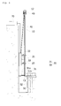
FIG. 1 is a side view showing the installation of a non-destructive test apparatus, according to an embodiment of the present invention; -
FIG. 2 is a rear view of the non-destructive test apparatus ofFIG. 1 ; -
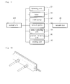
FIG. 3 is a block diagram showing a vacuum box of the non-destructive test apparatus ofFIG. 1 , elements for operating the vacuum box, and a control unit; -
FIGS. 4A through 4C are views showing embodiments of the vacuum box according to the present invention; and -
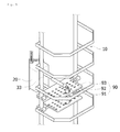
FIG. 5 is a view showing the vacuum box having a rotating unit according to the present invention. - Hereinafter, a preferred embodiment of the present invention will be described in detail with reference to the attached drawings. The following embodiment is only one example proposed to facilitate the understanding of the present invention, and those skilled in the art will appreciate that various modifications are possible. Therefore, the scope and spirit of the invention are not limited to the following embodiment.
-
FIG. 1 is a side view showing the installation of a non-destructive test apparatus, according to an embodiment of the present invention.FIG. 2 is a rear view of the non-destructive test apparatus ofFIG. 1 .FIG. 3 is a block diagram showing avacuum box 20 of the non-destructive test apparatus ofFIG. 1 , elements for operating thevacuum box 20, and acontrol unit 100. - As shown in
FIGS. 1 through 3 , in the non-destructive test apparatus according to the embodiment of the present invention, asupport frame 10 is installed adjacent to a target structure S1 to be tested, and thevacuum box 20 moves upwards or downwards along thesupport frame 10 to test whether the structure S1 is defective or not. This construction will be described in detail below. - The present invention can be typically used to test whether a structure constructed on the ground is defective or not and, in particular, it can be effectively used to test a structure which is constructed on a location, for example, an underwater location or an area contaminated by radioactivity, to which it is difficult for a worker to gain access. In the embodiment of the present invention, the case where the non-destructive test apparatus is used to test a structure which is under water will be explained.
- The
support frame 10 includesguide rails 11 which are disposed at left and right positions and extend predetermined lengths in the vertical direction. Furthermore, aholding part 12 which is hooked to a hook of a crane (not shown) is provided on the upper end of thesupport frame 10. Afastening part 13 is provided on the lower end of thesupport frame 10, so that thesupport frame 10 is fastened through thefastening part 13 to a fixture S2 which is around the structure S1. In addition, reinforcingbars 14 made of steel are provided between theguide rails 11 of thesupport frame 10 at positions spaced apart from each other at regular intervals to prevent thesupport frame 10, particularly, theguide rails 11, from being deformed. Thesupport frame 10 having the above-mentioned construction is constructed upright using the crane such that it is parallel with the outer wall of the structure S1 that is under water. - Furthermore, the present invention includes a
fastening unit 30 which fastens thesupport frame 10 to the structure S1 to prevent thesupport frame 10 from undesirably moving due to its own weight or an external force. Thefastening unit 30 includes acylinder actuator 31, and a fluid pressure supply unit (not shown) which supplies fluid pressure to thecylinder device 31. Here, thecylinder device 31 is called thefirst cylinder device 31 to distinguish it from asecond cylinder device 33 which is provided on thevacuum box 20 and will be explained later. In the embodiment of the present invention, pneumatic cylinders are used as thefirst cylinder device 31 and thesecond cylinder device 33. A typical air pressure supply unit having a valve, such as a four-way valve, is used as the fluid pressure supply unit. In the state in which thesupport frame 10 faces the structure S1, apiston rod 31a of thefirst cylinder device 31 is extracted from acylinder 31b thereof and is brought into close contact with the outer wall of the structure S1. Simultaneously, the fasteningpart 31 which is provided on the lower end of thesupport frame 10 is fastened to the fixture S2 which is around the structure S1. Thereby, the lower end of thesupport frame 10 is reliably fastened to the structure S1 without undesirably moving. Thevacuum box 20 is moved upwards or downwards along theguide rails 11 of thesupport frame 10. For this,wheels 21 which move along theguide rails 11 are provided on the rear surface of thevacuum box 20. Ahoist 40 is provided on the upper end of thesupport frame 10. Thehoist 40 is connected to thevacuum box 20 through awire 41 to move thevacuum box 20 upwards or downwards. Thevacuum box 20 may have various structures depending on the shape of the structure S1 to be tested.FIGS. 4a ,4b and 4c respectively illustrate examples of shapes corresponding to a planar portion, a concave corner between walls and a convex corner between walls. From among thesevacuum boxes 20, one corresponding to the shape of a portion of the structure S1 to be tested is mounted to thesupport frame 10. As mentioned above, thevacuum box 20 is coupled to thesupport frame 10 by thesecond cylinder device 33 constituting thefastening unit 30. To test whether the structure S1 is defective, thesecond cylinder device 33 is operated by fluid pressure generated from the fluid pressure supply unit, thus bringing thevacuum box 20 into close contact with the outer wall of the structure S1. In particular, a sealingmember 22 made of material, such as rubber, is provided on a corresponding side of thevacuum box 20 which comes into contact with the structure S1, such that when thevacuum box 20 is attached to the outer wall of the structure S1, the strength of the vacuum in thevacuum box 20 can be maintained constant. - The
vacuum box 20 is hollow. In the state in which thevacuum box 20 is attached to the surface of the structure S1, a vacuum is created therein. To achieve this purpose, the present invention further includes adrain pump 50 which is provided to remove, from thevacuum box 20, water which has been drawn into thevacuum box 20 when thevacuum box 20 was moved downwards along theguide rails 11 of thesupport frame 10 towards the structure S1 under water. Furthermore, the present invention further includes avacuum pump 60 which creates a vacuum in thevacuum box 20 as soon as water is removed from thevacuum box 20 by thedrain pump 50. If the non-destructive test apparatus of the present invention is applied to a structure constructed on the ground under dry conditions, thedrain pump 50 is unnecessary. - If a portion of the structure S1 to which the
vacuum box 20 is attached has a defect, for example, a crack, the strength of the vacuum in thevacuum box 20 which has been in the vacuum state is varied. The present invention further includes adefect detecting unit 70 which has a vacuum gauge (not shown) to detect variation in the strength of the vacuum in thevacuum box 20 and to determine whether it is defective. - Furthermore, the present invention may further include a
position indicating unit 80 which indicates the position of thevacuum box 20 such that when thevacuum box 20 moves upwards or downwards along thesupport frame 10, a user can easily observe whether thevacuum box 20 is exactly disposed at a target position of the structure S1 to be tested. Theposition indicating unit 80 includes a typical camera which is provided at a predetermined position on thesupport frame 10, and a monitor which displays images transmitted from the camera. - Furthermore, the present invention may further include a
rotating unit 90 which rotates thevacuum box 20 to the left or right towards the structure S1 in a diagonal direction (at an angle of θ°) with respect to the front surface of thesupport frame 10 such that thevacuum box 20 is brought into close contact with the wall of the structure S1 to be tested. For example, as shown inFIG. 5 , the rotatingunit 90 includes ahinge shaft 91 which is connected between thesupport frame 10 and the end of thesecond cylinder device 33 coupled to thevacuum box 20, and amotor 92 which rotates thehinge shaft 91. Themotor 92 is mounted on amovable panel 93 which moves along with thevacuum box 20 upwards or downwards along thesupport frame 10. - Meanwhile, the present invention further includes a
control unit 100 which allows the user to control the elements which move, fasten or rotate thevacuum box 20 with respect to thesupport frame 10 and create a vacuum in thevacuum box 20 to detect whether the structure S1 is defective, the elements including the hoist 40, thefastening unit 30, thevacuum pump 60, thedrain pump 50, theposition indicating unit 80 and the rotatingunit 90. - In the construction described above, pipes, wires and valves which are typically provided between the elements are omitted in the drawings to more clearly describe the present invention.
- The installation and operation of the non-destructive test apparatus according to the embodiment of the present invention having the above-mentioned construction will now be explained below.
- First, the
support frame 10 is installed adjacent to a desired portion of the structure S1 to be tested. For this, the holdingpart 12 provided on the upper end of thesupport frame 10 is hung on the hook of the crane, and, thereafter, thesupport frame 10 is disposed in front of the structure S1 using the crane. Subsequently, thefastening part 13 provided on the lower end of thesupport frame 10 approaches the fixture S2 which is around the structure S1. In this state, thefirst cylinder device 31 of thefastening unit 30 is operated. Then, thepiston rod 31a of thefirst cylinder device 31 is extracted from thecylinder 31b and is brought into close contact with the wall of the structure S1. Simultaneously, thefastening part 13 is brought into close contact with the fixture S2. Thereby, the lower end of thesupport frame 10 is supported between the structure S1 and the fixture S2, thus firmly fastening thesupport frame 10 to the structure S1. - Thereafter, the
vacuum box 20 is moved downwards along the guide rails 11 of thesupport frame 10 towards the desired portion of the structure S1 to be tested by operating the hoist 40. At this time, the user can observe whether thevacuum box 20 is disposed at the correct position using theposition indicating unit 80. After thevacuum box 20 is disposed at the desired portion of the structure S1 to be tested, thesecond cylinder device 33 of thefastening unit 30 is operated to bring thevacuum box 20 into close contact with the outer wall of the structure S1. To bring thevacuum box 20 into close contact with the outer wall of the structure S1, as necessary, the orientation of thevacuum box 20 relative to thesupport frame 10 may be adjusted by operating the rotatingunit 90 installed between thesecond cylinder device 33 of thevacuum box 20 and thesupport frame 10. - Meanwhile, in the process of bringing the
vacuum box 20 into close contact with the outer wall of the structure S1, after moving thevacuum box 20 along the guide rails 11 of thesupport frame 10, water enters thevacuum box 20. Therefore, after thevacuum box 20 has been brought into close contact with the outer wall of the structure S1, thedrain pump 50 is operated to remove water from thevacuum box 20. Furthermore, thevacuum pump 60 is operated to create a vacuum in thevacuum box 20 as soon as the removal of water from thevacuum box 20 is completed - After a predetermined time period has passed, variation in the strength of the vacuum in the
vacuum box 20 is measured using the vacuum gauge of thedefect detecting unit 70. If the strength of the vacuum in thevacuum box 20 varies, it is determined that the structure S1 is defective. - Thereafter, to test other portions of the structure S1, the
vacuum box 20 is moved upwards or downwards along the guide rails 11 of thesupport frame 10. The above-described process is repeated. - As described above, a non-destructive test apparatus according to the present invention can easily test whether a structure is defective or not without testing being difficult or risky, even if the structure is constructed not only on the ground in dry conditions but also in a location, for example, an underwater location or an area contaminated by radiation, to which it is difficult for a worker to get access.
- Although the preferred embodiment of the present invention has been disclosed for illustrative purposes, those skilled in the art will appreciate that various modifications, additions and substitutions are possible, without departing from the scope and spirit of the invention as disclosed in the accompanying claims.
Claims (5)
- A non-destructive test apparatus, comprising:a support frame (10) disposed adjacent to a target structure (51) to be tested for defects, the support frame having a vertical guide rail (11);a vacuum box (20) moving upwards or downwards along the guide rail of the support frame, the vacuum box being attached to the target structure and creating a vacuum therein;a hoist (40) provided on an upper end of the support frame to move the vacuum box upwards or downwards;a fastening unit (30) fastening the support frame and the vacuum box to the target structure;a vacuum pump (60) to create a vacuum in the vacuum box;a defect detecting unit (70) measuring a strength of vacuum in the vacuum box to determine whether the target structure is defective; anda control unit (100) to control at least one of the support frame, the vacuum box, the hoist, the fastening unit, the vacuum pump and the defect detecting unit.
- The non-destructive test apparatus as set forth in claim 1, further comprising:a drain pump (50) to remove water from the vacuum pump (60) under control of the control unit (100) when the vacuum pump is used under water.
- The non-destructive test apparatus as set forth in claim 1, further comprising:a position indicating unit (80) to display a position of the vacuum box (20) moving on the support frame (10) under control of the control unit (100) such that a user is able to check the position of the vacuum box.
- The non-destructive test apparatus as set forth in claim 1, wherein the fastening unit comprises:a first cylinder device (31) to removably fasten the support frame (10) to the target structure (51);a second cylinder device (33) to removably fasten the vacuum box (20) to the target structure (51); anda fluid pressure supply unit to supply fluid pressure to the first cylinder device and the second cylinder device.
- The non-destructive test apparatus as set forth in claim 1, further comprising:a rotating unit (90) to rotate the vacuum box (20) leftwards or rightwards with respect to the target structure (51) under control of the control unit (100).
Applications Claiming Priority (1)
| Application Number | Priority Date | Filing Date | Title |
|---|---|---|---|
| KR1020080101516A KR100996233B1 (en) | 2008-10-16 | 2008-10-16 | Non-destructive test equipment |
Publications (2)
| Publication Number | Publication Date |
|---|---|
| EP2177887A2 true EP2177887A2 (en) | 2010-04-21 |
| EP2177887A3 EP2177887A3 (en) | 2015-12-23 |
Family
ID=41514984
Family Applications (1)
| Application Number | Title | Priority Date | Filing Date |
|---|---|---|---|
| EP09159690.8A Withdrawn EP2177887A3 (en) | 2008-10-16 | 2009-05-07 | Non-destructive test apparatus |
Country Status (5)
| Country | Link |
|---|---|
| US (1) | US8091440B2 (en) |
| EP (1) | EP2177887A3 (en) |
| JP (1) | JP5096407B2 (en) |
| KR (1) | KR100996233B1 (en) |
| CN (1) | CN101726449B (en) |
Cited By (3)
| Publication number | Priority date | Publication date | Assignee | Title |
|---|---|---|---|---|
| CN103940726A (en) * | 2014-04-04 | 2014-07-23 | 清华大学 | Steel chimney corrosion monitoring system and method based on non-contact ultrasonic technology |
| WO2020131436A1 (en) * | 2018-12-17 | 2020-06-25 | National Oilwell Varco, L.P. | Pressure-based flaw detection |
| WO2020234192A1 (en) * | 2019-05-21 | 2020-11-26 | Gaztransport Et Technigaz | Bell-shaped leak detection device and method for using same |
Families Citing this family (11)
| Publication number | Priority date | Publication date | Assignee | Title |
|---|---|---|---|---|
| US8573032B2 (en) * | 2009-03-30 | 2013-11-05 | Areva Np Inc | Underwater method and apparatus for detecting leaks in a metallic tank or pit liner plate |
| US8640558B2 (en) * | 2011-09-12 | 2014-02-04 | Honeywell International Inc. | System for the automated inspection of structures at height |
| DE102012205013B4 (en) * | 2011-12-13 | 2015-11-26 | Areva Gmbh | Apparatus and method for repairing a damaged area in a submerged wall area of a container or basin |
| KR101260193B1 (en) | 2011-12-16 | 2013-05-06 | 한국항공우주연구원 | Device and method for leak sensing |
| CN102564707B (en) * | 2011-12-22 | 2014-10-22 | 河海大学 | Device for detecting water leakage of gate and control method thereof |
| CN104296945A (en) * | 2013-07-15 | 2015-01-21 | 珠海格力电器股份有限公司 | Evaporator leak detection system and leak detection method |
| US9404848B2 (en) * | 2014-03-11 | 2016-08-02 | The Boeing Company | Apparatuses and methods for testing adhesion of a seal to a surface |
| KR101416033B1 (en) * | 2014-05-15 | 2014-07-09 | (주)인스펙트 | Film cartridge automatic supply apparatus for radiographic inspection |
| CN105865725A (en) * | 2016-04-25 | 2016-08-17 | 昆山瑞鸿诚自动化设备科技有限公司 | Airtightness test fixture |
| US9920754B2 (en) | 2016-05-09 | 2018-03-20 | The Goodyear Tire & Rubber Company | Air maintenance tire pump simulator |
| KR102581149B1 (en) * | 2021-05-04 | 2023-09-21 | 유양원자 주식회사 | Non-destructive inspection system capable of performing both vacuum leakage inspection and phased array ultrasonic inspection for storage tanks |
Family Cites Families (50)
| Publication number | Priority date | Publication date | Assignee | Title |
|---|---|---|---|---|
| US1616743A (en) * | 1922-12-29 | 1927-02-08 | Ericsson Henry | Scaffold |
| US3524342A (en) * | 1968-06-10 | 1970-08-18 | Rohr Corp | Apparatus for detecting surface leakage |
| BE795542A (en) * | 1972-02-18 | 1973-06-18 | Dynamit Nobel Ag | METHOD AND DEVICE FOR CHECKING THE LEAKAGE OF THE WELDING CORDS OF PLASTIC STRIPS IN A VACUUM |
| US3808876A (en) * | 1972-10-02 | 1974-05-07 | T Kershaw | Air permeability tester |
| US3827283A (en) * | 1973-03-05 | 1974-08-06 | Sun Oil Co | Fluid leakage measuring apparatus |
| US3889521A (en) * | 1974-05-15 | 1975-06-17 | Nat Steel Corp | Static gas pressure measuring device |
| JPS5737239A (en) * | 1980-08-19 | 1982-03-01 | Mitsubishi Heavy Ind Ltd | Apparatus for detecting leakage in tank wall |
| JPS5882154A (en) * | 1981-11-10 | 1983-05-17 | Mitsubishi Electric Corp | Lifting gear for water examination instrument |
| US4498556A (en) * | 1982-09-11 | 1985-02-12 | Access Engineering Ltd. | Vertically movable, road towable work platform |
| JPS60205242A (en) | 1984-03-30 | 1985-10-16 | Toshiba Corp | Method and apparatus for inspecting defect of member in liquid |
| FI77331C (en) * | 1986-04-10 | 1989-02-10 | Valmet Oy | FOERFARANDE OCH ANORDNING FOER MAETNING AV LUFTGENOMTRAENGLIGHETEN HOS EN VAEGG, SAERSKILT EN VIRA ELLER FILT I EN PAPPERSMASKIN. |
| JPS6315132A (en) * | 1986-07-08 | 1988-01-22 | Ozawa Concrete Kogyo Kk | Method for testing airtightness of concrete panel material |
| EP0325586B1 (en) * | 1986-08-07 | 1991-06-12 | Secretary of State for the Environment in Her Britannic Majesty's Gov. of the U.K. of Great Britain and Northern Ireland | Fluctuating stress generating apparatus and method |
| JPH0820546B2 (en) * | 1987-10-30 | 1996-03-04 | 株式会社東芝 | In-reactor inspection device |
| JPH022933A (en) * | 1988-06-15 | 1990-01-08 | Hitachi Ltd | Mobile flaw detecting apparatus and tank thereof |
| US4979390A (en) * | 1988-12-01 | 1990-12-25 | Morris Schupack | Method and apparatus for testing relative permeability of materials |
| CN2052534U (en) * | 1989-03-22 | 1990-02-07 | 四川工业学院 | Combined nondestructive testing device for vacuum of tin |
| JPH02291957A (en) * | 1989-05-02 | 1990-12-03 | Ishikawajima Harima Heavy Ind Co Ltd | Heat-exchanger inspecting apparatus |
| CN2056755U (en) * | 1989-09-01 | 1990-05-02 | 邓继尧 | Nondestructive detector for can vacuum degree |
| JPH04102037A (en) * | 1990-08-21 | 1992-04-03 | Nippon Petrochem Co Ltd | Method and apparatus for inspecting leakage of sheet material |
| US5163333A (en) * | 1990-11-28 | 1992-11-17 | The Center For Innovative Technology By Mesne Assignment From The University Of Virginia | Back and trunk positioning and shape sensing apparatus |
| US5318254A (en) * | 1991-06-28 | 1994-06-07 | Conceptual Solutions, Inc. | Aircraft maintenance robot |
| JP2562248B2 (en) * | 1992-02-10 | 1996-12-11 | 動力炉・核燃料開発事業団 | Underwater defect detection method |
| US5257088A (en) * | 1992-03-27 | 1993-10-26 | Laser Technology, Inc. | Apparatus and method for nondestructive inspection of a vehicle |
| JPH0626973A (en) * | 1992-07-09 | 1994-02-04 | Mitsubishi Heavy Ind Ltd | Inspecting device for leak from welded part |
| US5503033A (en) * | 1993-08-10 | 1996-04-02 | Tric Holdings Limited | Method and servicing interior of large container and service apparatus |
| FI94552C (en) * | 1993-09-14 | 1995-09-25 | Auramo Oy | Apparatus for measuring paper roll shape defects |
| SE506031C2 (en) * | 1993-12-28 | 1997-11-03 | Abb Tekniska Roentgencent | Apparatus and method for inspecting a reactor vessel |
| US5643476A (en) * | 1994-09-21 | 1997-07-01 | University Of Southern California | Laser system for removal of graffiti |
| US5574233A (en) * | 1994-10-17 | 1996-11-12 | Amsted Industries Incorporated | Non-contact railway wheel test apparatus and method |
| US5852984A (en) * | 1996-01-31 | 1998-12-29 | Ishikawajimi-Harima Heavy Industries Co., Ltd. | Underwater vehicle and method of positioning same |
| US5858111A (en) * | 1997-01-21 | 1999-01-12 | Marrero; Lou | Aircraft maintenance apparatus and method of maintaining same |
| US6134734A (en) * | 1997-01-21 | 2000-10-24 | Marrero; Lou | Aircraft maintenance apparatus and method of maintaining aircraft |
| JP3604535B2 (en) * | 1997-07-17 | 2004-12-22 | 株式会社東芝 | Reactor inspection and repair equipment |
| JP2001033345A (en) * | 1999-07-15 | 2001-02-09 | Toshiba Corp | Device and method for automatically judging airtightness of lightning arrester |
| JP2002005923A (en) | 2000-06-27 | 2002-01-09 | Nippon Kayaku Wasser Kk | Inspection method and device for concrete structure |
| US6378387B1 (en) * | 2000-08-25 | 2002-04-30 | Aerobotics, Inc. | Non-destructive inspection, testing and evaluation system for intact aircraft and components and method therefore |
| JP2002340757A (en) * | 2001-05-14 | 2002-11-27 | Hitachi Ltd | Surface inspection apparatus of underwater structure |
| US6636581B2 (en) * | 2001-08-31 | 2003-10-21 | Michael R. Sorenson | Inspection system and method |
| US6907799B2 (en) * | 2001-11-13 | 2005-06-21 | Bae Systems Advanced Technologies, Inc. | Apparatus and method for non-destructive inspection of large structures |
| JP3850724B2 (en) * | 2001-12-19 | 2006-11-29 | 株式会社東芝 | Reactor internal structure maintenance and repair equipment |
| US6646431B1 (en) * | 2002-01-22 | 2003-11-11 | Elite E/M, Inc. | Test head manipulator |
| US20030177850A1 (en) * | 2002-03-19 | 2003-09-25 | The Washington Post Company | System and method for verifying the roll roundness of rolls of paper used for newspapers |
| US7235964B2 (en) * | 2003-03-31 | 2007-06-26 | Intest Corporation | Test head positioning system and method |
| US6792809B1 (en) * | 2003-05-02 | 2004-09-21 | Siemens Westinghouse Power Corporation | Self-aligning turbine disc inspection apparatus |
| JP2006526785A (en) * | 2003-06-02 | 2006-11-24 | アール. ブルックス アソシエイツ インコーポレーティッド | Method and apparatus for inspecting reactor head components |
| US20060213274A1 (en) * | 2005-03-22 | 2006-09-28 | Siemens Westinghouse Power Corporation | Nondestructive inspection heads for components having limited surrounding space |
| US7716989B2 (en) * | 2005-08-16 | 2010-05-18 | The Boeing Company | Collapsible guide for non-automated area inspections |
| US7765853B2 (en) * | 2007-06-04 | 2010-08-03 | The Boeing Company | Determining seal feature integrity by testing for deformation upon air pressure excitation |
| US8122776B2 (en) * | 2008-06-13 | 2012-02-28 | Fox Michael A | Handheld vacuum test fixture and method of monitoring vacuum cup differential pressure |
-
2008
- 2008-10-16 KR KR1020080101516A patent/KR100996233B1/en active IP Right Grant
-
2009
- 2009-04-24 JP JP2009106275A patent/JP5096407B2/en active Active
- 2009-04-30 CN CN2009101361646A patent/CN101726449B/en active Active
- 2009-05-07 EP EP09159690.8A patent/EP2177887A3/en not_active Withdrawn
- 2009-05-08 US US12/437,786 patent/US8091440B2/en active Active
Cited By (6)
| Publication number | Priority date | Publication date | Assignee | Title |
|---|---|---|---|---|
| CN103940726A (en) * | 2014-04-04 | 2014-07-23 | 清华大学 | Steel chimney corrosion monitoring system and method based on non-contact ultrasonic technology |
| WO2020131436A1 (en) * | 2018-12-17 | 2020-06-25 | National Oilwell Varco, L.P. | Pressure-based flaw detection |
| US11307114B2 (en) | 2018-12-17 | 2022-04-19 | National Oilwell Varco, L.P. | Pressure-based flaw detection |
| WO2020234192A1 (en) * | 2019-05-21 | 2020-11-26 | Gaztransport Et Technigaz | Bell-shaped leak detection device and method for using same |
| FR3096457A1 (en) * | 2019-05-21 | 2020-11-27 | Gaztransport Et Technigaz | LEAK DETECTION BELL AND ITS PROCESS FOR USE |
| CN113874698A (en) * | 2019-05-21 | 2021-12-31 | 气体运输技术公司 | Bell-shaped leakage detection device and method using same |
Also Published As
| Publication number | Publication date |
|---|---|
| US20100095748A1 (en) | 2010-04-22 |
| KR100996233B1 (en) | 2010-11-23 |
| JP2010096741A (en) | 2010-04-30 |
| EP2177887A3 (en) | 2015-12-23 |
| JP5096407B2 (en) | 2012-12-12 |
| CN101726449A (en) | 2010-06-09 |
| CN101726449B (en) | 2011-07-27 |
| KR20100042382A (en) | 2010-04-26 |
| US8091440B2 (en) | 2012-01-10 |
Similar Documents
| Publication | Publication Date | Title |
|---|---|---|
| US8091440B2 (en) | Non-destructive test apparatus | |
| KR101179929B1 (en) | Safety diagnosis device for bridge | |
| CN206891852U (en) | A kind of cantilever bending fatigue experimental device and home position observation device | |
| JP2014218886A (en) | Survey and repair method for concrete structure facing narrow expansion gap | |
| KR102334136B1 (en) | Rail-type automatic ultrasonic testing device | |
| CN204758466U (en) | High temperature water under high pressure or steam environment fine motion abrasion tester | |
| CN102598151B (en) | Device for assisting in the underwater extraction or insertion of an elongate element disposed in a pipe, and method for assisting in the extraction or insertion of one such element | |
| JP6025638B2 (en) | In-reactor investigation method and investigation apparatus | |
| DE102005008308B4 (en) | Method for leak detection on leak-proof linings of tanks and containers or the like | |
| KR102327866B1 (en) | Inspection and thickness measurement apparatus for reactor containment building liner plate | |
| KR101910473B1 (en) | Localized leak detection apparatus for the metal containment vessel of nuclear power | |
| JP2016001151A (en) | Wall surface image acquisition apparatus | |
| JPH1172484A (en) | Flange-related inspection device of atomic reactor | |
| KR102146208B1 (en) | Ultrasonic testing device | |
| JP5901281B2 (en) | Underwater hole measuring device and underwater reracing method using the device | |
| KR101216754B1 (en) | Apparatus for inspecting inside diameter surfaces and threads of a stud | |
| JP5722129B2 (en) | Tank soundness diagnosis method and guided wave inspection device | |
| JP6315605B2 (en) | Structure shooting system | |
| KR102487732B1 (en) | Testing apparatus of auto-scanner for phased array ultrasonic inspection | |
| JP5606844B2 (en) | Method and apparatus for diagnosing cracks in furnace structures | |
| KR102259924B1 (en) | Apparatus for inspecting head of nuclear reactor | |
| JP3518824B2 (en) | Furnace structure visual inspection device | |
| JP6080147B2 (en) | Underwater long tubular member suspension device and underwater reracing method using the device | |
| JP6374230B2 (en) | Wall image acquisition device | |
| JPS599553A (en) | Detector for flaw in steel material |
Legal Events
| Date | Code | Title | Description |
|---|---|---|---|
| PUAI | Public reference made under article 153(3) epc to a published international application that has entered the european phase |
Free format text: ORIGINAL CODE: 0009012 |
|
| AK | Designated contracting states |
Kind code of ref document: A2 Designated state(s): AT BE BG CH CY CZ DE DK EE ES FI FR GB GR HR HU IE IS IT LI LT LU LV MC MK MT NL NO PL PT RO SE SI SK TR |
|
| PUAL | Search report despatched |
Free format text: ORIGINAL CODE: 0009013 |
|
| AK | Designated contracting states |
Kind code of ref document: A3 Designated state(s): AT BE BG CH CY CZ DE DK EE ES FI FR GB GR HR HU IE IS IT LI LT LU LV MC MK MT NL NO PL PT RO SE SI SK TR |
|
| RIC1 | Information provided on ipc code assigned before grant |
Ipc: B65D 90/50 20060101ALI20151116BHEP Ipc: B63C 11/34 20060101ALI20151116BHEP Ipc: G01M 3/04 20060101AFI20151116BHEP Ipc: G01M 3/26 20060101ALI20151116BHEP Ipc: B29C 65/82 20060101ALI20151116BHEP Ipc: G21C 17/01 20060101ALI20151116BHEP |
|
| STAA | Information on the status of an ep patent application or granted ep patent |
Free format text: STATUS: THE APPLICATION IS DEEMED TO BE WITHDRAWN |
|
| 18D | Application deemed to be withdrawn |
Effective date: 20160624 |