EP2177797A1 - Klappenventil für eine Verbrennungskraftmaschine - Google Patents
Klappenventil für eine Verbrennungskraftmaschine Download PDFInfo
- Publication number
- EP2177797A1 EP2177797A1 EP09168736A EP09168736A EP2177797A1 EP 2177797 A1 EP2177797 A1 EP 2177797A1 EP 09168736 A EP09168736 A EP 09168736A EP 09168736 A EP09168736 A EP 09168736A EP 2177797 A1 EP2177797 A1 EP 2177797A1
- Authority
- EP
- European Patent Office
- Prior art keywords
- flap
- valve
- shaft
- valve body
- valve according
- Prior art date
- Legal status (The legal status is an assumption and is not a legal conclusion. Google has not performed a legal analysis and makes no representation as to the accuracy of the status listed.)
- Withdrawn
Links
- 238000002485 combustion reaction Methods 0.000 title claims description 3
- 230000002093 peripheral effect Effects 0.000 claims description 6
- 238000004519 manufacturing process Methods 0.000 description 2
- 230000002411 adverse Effects 0.000 description 1
Images
Classifications
-
- F—MECHANICAL ENGINEERING; LIGHTING; HEATING; WEAPONS; BLASTING
- F16—ENGINEERING ELEMENTS AND UNITS; GENERAL MEASURES FOR PRODUCING AND MAINTAINING EFFECTIVE FUNCTIONING OF MACHINES OR INSTALLATIONS; THERMAL INSULATION IN GENERAL
- F16K—VALVES; TAPS; COCKS; ACTUATING-FLOATS; DEVICES FOR VENTING OR AERATING
- F16K1/00—Lift valves or globe valves, i.e. cut-off apparatus with closure members having at least a component of their opening and closing motion perpendicular to the closing faces
- F16K1/16—Lift valves or globe valves, i.e. cut-off apparatus with closure members having at least a component of their opening and closing motion perpendicular to the closing faces with pivoted closure-members
- F16K1/18—Lift valves or globe valves, i.e. cut-off apparatus with closure members having at least a component of their opening and closing motion perpendicular to the closing faces with pivoted closure-members with pivoted discs or flaps
- F16K1/22—Lift valves or globe valves, i.e. cut-off apparatus with closure members having at least a component of their opening and closing motion perpendicular to the closing faces with pivoted closure-members with pivoted discs or flaps with axis of rotation crossing the valve member, e.g. butterfly valves
- F16K1/222—Shaping of the valve member
-
- F—MECHANICAL ENGINEERING; LIGHTING; HEATING; WEAPONS; BLASTING
- F02—COMBUSTION ENGINES; HOT-GAS OR COMBUSTION-PRODUCT ENGINE PLANTS
- F02D—CONTROLLING COMBUSTION ENGINES
- F02D9/00—Controlling engines by throttling air or fuel-and-air induction conduits or exhaust conduits
- F02D9/08—Throttle valves specially adapted therefor; Arrangements of such valves in conduits
- F02D9/10—Throttle valves specially adapted therefor; Arrangements of such valves in conduits having pivotally-mounted flaps
- F02D9/1005—Details of the flap
- F02D9/1025—Details of the flap the rotation axis of the flap being off-set from the flap center axis
-
- F—MECHANICAL ENGINEERING; LIGHTING; HEATING; WEAPONS; BLASTING
- F02—COMBUSTION ENGINES; HOT-GAS OR COMBUSTION-PRODUCT ENGINE PLANTS
- F02D—CONTROLLING COMBUSTION ENGINES
- F02D9/00—Controlling engines by throttling air or fuel-and-air induction conduits or exhaust conduits
- F02D9/08—Throttle valves specially adapted therefor; Arrangements of such valves in conduits
- F02D9/10—Throttle valves specially adapted therefor; Arrangements of such valves in conduits having pivotally-mounted flaps
- F02D9/1035—Details of the valve housing
- F02D9/104—Shaping of the flow path in the vicinity of the flap, e.g. having inserts in the housing
- F02D9/1045—Shaping of the flow path in the vicinity of the flap, e.g. having inserts in the housing for sealing of the flow in closed flap position, e.g. the housing forming a valve seat
Definitions
- the invention relates to a flap valve for an internal combustion engine with a flap nozzle, in which a flap shaft is mounted, on which a flap is arranged symmetrically inclined so that the flap strikes in the closed state of the flap valve on the inside of the flap body.
- Such a flap valve is for example from the DE 103 59 609 A1 known.
- This document discloses a flap valve in which the flap is arranged symmetrically inclined on the flap shaft. In this way, a peripheral system of the flap can be ensured because the bearings of such a flap shaft are no longer in the flap. The problem of leakage through the bearings of the valve shaft should be resolved.
- the flap in order to ensure a tight fit of the throttle valve to the inner wall of the valve body in the closed state, the flap has a circumferential seal.
- Such a flap valve designed is relatively expensive to manufacture, since the seal either procured as an additional component and must be mounted, or is to be formed for example by means of mounting syringes.
- the invention is therefore based on the object to provide a flap valve that the o. G. Disadvantage avoids.
- the flap is designed elliptical and that on the inside of the valve body flap release surfaces are provided, which are designed such that the flap is pivotable in a fully open state ..
- the main axis of the elliptical flap extends in the fully open state parallel to the flow direction in the flap neck. It is also advantageous for ease of manufacture, when the flow cross-section of the valve body is circular.
- the minor axis of the flap includes an angle a of 10-45 degrees with the shaft axis of the flap shaft. Furthermore, it is advantageous if the peripheral surface of the flap is chamfered such that upon abutment of the flap, this circumferential surface bears against the inside of the flap neck.
- the flap shaft is mounted only on one side / simply.
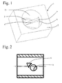
- FIG. 1 shows a flap valve according to the invention 1.
- This flap valve 1 has a flap nozzle 2 with a circular flow cross-section, in which a flap shaft 3 is mounted in a known manner. On this flap shaft, a flap 4 is arranged symmetrically inclined. The flap 4 is elliptical.
- the peripheral surface 7 of the flap 4 is chamfered such that upon abutment of the flap 4, this peripheral surface 7 rests against the inside 5 of the valve neck 2 (see also FIG. 3 ).
- FIG. 2 shows now in a schematic sectional view of the flap nozzle 2 with a shaft bore 8 for receiving the flap shaft 3 and one of the two flap release surfaces. 6
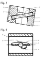
- FIG. 3 shows the flap nozzle 2 in a sectional view with the flap 4 in the fully closed position.
- Bearings 9 for the valve shaft 3 are completely arranged in the valve nozzle 2, whereby the flow is not adversely affected by protruding bearing parts.
- the flap release surfaces 6 are to be selected depending on the angle ⁇ , which is enclosed between the minor axis of the elliptical flap 4 and the shaft axis of the flap shaft 3.
- the angle range for ⁇ is usefully between 10 and 45 degrees.
- the flap 4 is also designed as a punched / bent part.
Landscapes
- Engineering & Computer Science (AREA)
- General Engineering & Computer Science (AREA)
- Mechanical Engineering (AREA)
- Chemical & Material Sciences (AREA)
- Combustion & Propulsion (AREA)
- Lift Valve (AREA)
Abstract
Description
- Die Erfindung betrifft ein Klappenventil für eine Verbrennungskraftmaschine mit einem Klappenstutzen, in dem eine Klappenwelle gelagert ist, auf welcher eine Klappe symmetrisch schräg verlaufend derart angeordnet ist, dass die Klappe in geschlossenem Zustand des Klappenventils an der Innenseite des Klappenstutzens anschlägt.
- Ein derartiges Klappenventil ist beispielsweise aus der
DE 103 59 609 A1 bekannt. Diese Druckschrift offenbart ein Klappenventil, bei dem die Klappe symmetrisch schräg verlaufend auf der Klappenwelle angeordnet ist. Auf diese Weise kann eine umlaufende Anlage der Klappe gewährleistet werden, da die Lagerstellen einer derartigen Klappenwelle nicht mehr im Bereich der Klappe liegen. Das Problem einer Leckage über die Lagerstellen der Klappenwelle soll damit behoben sein. Um jedoch im geschlossenen Zustand ein dichtes Anliegen der Drosselklappe an die Innenwand des Klappenstutzens zu gewährleisten, besitzt die Klappe eine umlaufende Dichtung. Ein derartig ausgeführtes Klappenventil ist relativ teuer in der Herstellung, da die Dichtung entweder als zusätzliches Bauteil beschafft und montiert werden muss, oder beispielsweise mittels Montagespritzen anzuformen ist. - Der Erfindung liegt daher die Aufgabe zu Grunde, ein Klappenventil zu verschaffen, dass den o. g. Nachteil vermeidet.
- Diese Aufgabe wird durch die Erfindung dadurch gelöst, dass die Klappe elliptisch ausgeführt ist und dass an der Innenseite des Klappenstutzens Klappenfreigangsflächen vorgesehen sind, die derart ausgebildet sind, dass die Klappe in einen voll geöffneten Zustand schwenkbar ist.. Auf diese Weise wird ein Klappenventil mit einer Klappe, die symmetrisch schräg auf der Klappenwelle angeordnet ist, geschaffen, wobei die Klappe ohne zusätzliche Abdichtungen, wie zum Beispiel eine umlaufende Dichtung, fluiddicht an der Innenseite des Klappenstutzens anliegen kann.
- In einer besonders vorteilhaften Ausführungsform verläuft die Hauptachse der elliptisch ausgebildeten Klappe in voll geöffnetem Zustand parallel zur Strömungsrichtung im Klappenstutzen. Auch ist es für eine einfache Herstellung vorteilhaft, wenn der Strömungsquerschnitt des Klappenstutzens kreisrund ist.
- Vorzugsweise schließt die Nebenachse der Klappe mit der Wellenachse der Klappenwelle einen Winkel a von 10 - 45 Grad ein. Weiterhin ist es vorteilhaft, wenn die Umfangsfläche der Klappe derart angeschrägt ist, dass bei Anschlag der Klappe diese Umfangsfläche an der Innenseite des Klappenstutzens anliegt.
- Des Weiteren ist es denkbar, dass die Klappenwelle lediglich einseitig / einfach gelagert ist.
- Im Folgenden wird unter Bezugnahme auf die Zeichnung ein Ausführungsbeispiel der Erfindung näher erläutert, hierin zeigt:
-
Figur 1 eine perspektivische Ansicht des erfindungsgemäßen Klappenventils, -
Figur 2 eine schematische Schnittansicht des Klappenstutzens ohne Klappenwelle und Klappe, -
Figur 3 eine schematische Schnittansicht des Klappenstutzens mit Klappenwelle und Klappe im geschlossenen Zustand, und -
Figur 4 eine schematische Schnittansicht des Klappenstutzens mit Klappenwelle und Klappe in geöffnetem Zustand. -
Figur 1 zeigt ein erfindungsgemäßes Klappenventil 1. Dieses Klappenventil 1 weist einen Klappenstutzen 2 mit einem kreisrunden Strömungsquerschnitt auf, in dem auf bekannte Weise eine Klappenwelle 3 gelagert ist. Auf dieser Klappenwelle ist eine Klappe 4 symmetrisch schräg verlaufend angeordnet. Die Klappe 4 ist elliptisch ausgeführt. An der Innenseite 5 des Klappenstutzens 2 sind Klappenfreigangsflächen 6, von denen jedoch nur eine in der Ansicht zu erkennen ist, vorgesehen. Diese Klappenfreigangsflächen 6 ermöglichen ein vollständiges Öffnen der elliptischen Klappe 4 im Klappenstutzen 2. Desweiteren ist die Umfangsfläche 7 der Klappe 4 derart angeschrägt ist, dass bei Anschlag der Klappe 4 diese Umfangsfläche 7 an der Innenseite 5 des Klappenstutzens 2 anliegt ( siehe auchFigur 3 ). -
Figur 2 zeigt nun in einer schematischen Schnittansicht den Klappenstutzen 2 mit einer Wellenbohrung 8 zur Aufnahme der Klappenwelle 3 sowie einer der beiden Klappenfreigangsflächen 6. -
Figur 3 zeigt den Klappenstutzen 2 in Schnittansicht mit der Klappe 4 in vollständig geschlossener Stellung. Lager 9 für die Klappenwelle 3 sind vollständig im Klappenstutzen 2 angeordnet, wodurch die Strömung nicht durch vorstehende Lagerteile negativ beeinflusst wird. - Um nun gemäß
Figur 4 in eine vollständig geöffnete Stellung verschwenkt werden zu können, schwenkt die Klappe 4 in die Klappenfreigangsflächen 6 hinein. Die Hauptachse der elliptisch ausgebildeten Klappe 4 verläuft nun parallel zur Strömungsrichtung im Klappenstutzen 2. - Dabei sind die Klappenfreigangsflächen 6 abhängig vom Winkel α zu wählen, der zwischen der Nebenachse der ellipsenförmigen Klappe 4 und der Wellenachse der Klappenwelle 3 eingeschlossen wird. Der Winkelbereich für α liegt dabei sinnvollerweise zwischen 10 und 45 Grad.
- Darüber hinaus ist es möglich, dass die Klappe 4 auch als Stanz-/Biegeteil ausgeführt wird.
- Auch ist es natürlich möglich die Klappe 4 lediglich einseitig im Klappenstutzen 2 zu lagern.
Claims (6)
- Klappenventil (1) für eine Verbrennungskraftmaschine mit einem Klappenstutzen (2), in dem eine Klappenwelle (3) gelagert ist, auf welcher eine Klappe (4) symmetrisch schräg verlaufend derart angeordnet ist, dass die Klappe (4) in geschlossenem Zustand des Klappenventils (1) an der Innenseite des Klappenstutzens (2) anschlägt,
dadurch gekennzeichnet, dass die Klappe (4) elliptisch ausgeführt ist und dass an der Innenseite (5) des Klappenstutzens (2) Klappenfreigangsflächen (6) vorgesehen sind, die derart ausgebildet sind, dass die Klappe in einen voll geöffneten Zustand schwenkbar ist. - Klappenventil nach Anspruch 1, dadurch gekennzeichnet, dass die Hauptachse der elliptisch ausgebildeten Klappe (4) in voll geöffnetem Zustand parallel zur Strömungsrichtung im Klappenstutzen (2) verläuft.
- Klappenventil nach Anspruch 1 oder 2, dadurch gekennzeichnet, dass der Strömungsquerschnitt des Klappenstutzens (2) kreisrund ist.
- Klappenventil nach einem der vorhergehenden Ansprüche, dadurch gekennzeichnet, dass die Nebenachse der Klappe (4) mit der Wellenachse der Klappenwelle (3) einen Winkel α von 10 - 45 Grad einschließt.
- Klappenventil nach einem der vorhergehenden Ansprüche, dadurch gekennzeichnet, dass die Umfangsfläche (7) der Klappe (4) derart angeschrägt ist, dass bei Anschlag der Klappe (4) diese Umfangsfläche (7) an der Innenseite (5) des Klappenstutzens (3) anliegt.
- Klappenventil nach einem der vorhergehenden Ansprüche, dadurch gekennzeichnet, dass die Klappenwelle (3) einseitig gelagert ist.
Applications Claiming Priority (1)
| Application Number | Priority Date | Filing Date | Title |
|---|---|---|---|
| DE200810051339 DE102008051339B3 (de) | 2008-10-15 | 2008-10-15 | Klappenventil für eine Verbrennungskraftmaschine |
Publications (1)
| Publication Number | Publication Date |
|---|---|
| EP2177797A1 true EP2177797A1 (de) | 2010-04-21 |
Family
ID=41318026
Family Applications (1)
| Application Number | Title | Priority Date | Filing Date |
|---|---|---|---|
| EP09168736A Withdrawn EP2177797A1 (de) | 2008-10-15 | 2009-08-26 | Klappenventil für eine Verbrennungskraftmaschine |
Country Status (2)
| Country | Link |
|---|---|
| EP (1) | EP2177797A1 (de) |
| DE (1) | DE102008051339B3 (de) |
Cited By (1)
| Publication number | Priority date | Publication date | Assignee | Title |
|---|---|---|---|---|
| WO2013102562A1 (de) * | 2012-01-03 | 2013-07-11 | Continental Automotive Gmbh | Ventilvorrichtung für ein kraftfahrzeug |
Families Citing this family (1)
| Publication number | Priority date | Publication date | Assignee | Title |
|---|---|---|---|---|
| DE102009033411B4 (de) * | 2009-07-15 | 2012-10-31 | Pierburg Gmbh | Klappenventil für eine Verbrennungskraftmaschine |
Citations (6)
| Publication number | Priority date | Publication date | Assignee | Title |
|---|---|---|---|---|
| GB759111A (en) * | 1953-10-30 | 1956-10-10 | Garrett Corp | Improvements in or relating to valve with deformable seat |
| US3480254A (en) * | 1968-02-12 | 1969-11-25 | Pratt Co Henry | Angle seating butterfly valve with skewed disc |
| US3627261A (en) | 1969-09-17 | 1971-12-14 | Andrews Ind Inc | Balanced rotary plate valve and method of making |
| DE19934113A1 (de) * | 1999-07-21 | 2001-01-25 | Bosch Gmbh Robert | Klappenventil |
| WO2003019052A1 (de) * | 2001-08-24 | 2003-03-06 | Robert Bosch Gmbh | Klappenventil |
| DE10359609A1 (de) | 2003-12-18 | 2005-07-28 | Siemens Ag | Drosselklappenstutzen |
-
2008
- 2008-10-15 DE DE200810051339 patent/DE102008051339B3/de not_active Expired - Fee Related
-
2009
- 2009-08-26 EP EP09168736A patent/EP2177797A1/de not_active Withdrawn
Patent Citations (6)
| Publication number | Priority date | Publication date | Assignee | Title |
|---|---|---|---|---|
| GB759111A (en) * | 1953-10-30 | 1956-10-10 | Garrett Corp | Improvements in or relating to valve with deformable seat |
| US3480254A (en) * | 1968-02-12 | 1969-11-25 | Pratt Co Henry | Angle seating butterfly valve with skewed disc |
| US3627261A (en) | 1969-09-17 | 1971-12-14 | Andrews Ind Inc | Balanced rotary plate valve and method of making |
| DE19934113A1 (de) * | 1999-07-21 | 2001-01-25 | Bosch Gmbh Robert | Klappenventil |
| WO2003019052A1 (de) * | 2001-08-24 | 2003-03-06 | Robert Bosch Gmbh | Klappenventil |
| DE10359609A1 (de) | 2003-12-18 | 2005-07-28 | Siemens Ag | Drosselklappenstutzen |
Cited By (4)
| Publication number | Priority date | Publication date | Assignee | Title |
|---|---|---|---|---|
| WO2013102562A1 (de) * | 2012-01-03 | 2013-07-11 | Continental Automotive Gmbh | Ventilvorrichtung für ein kraftfahrzeug |
| CN104024604A (zh) * | 2012-01-03 | 2014-09-03 | 大陆汽车有限责任公司 | 用于机动车的阀装置 |
| KR20140108654A (ko) * | 2012-01-03 | 2014-09-12 | 콘티넨탈 오토모티브 게엠베하 | 자동차용 밸브 장치 |
| US10358986B2 (en) | 2012-01-03 | 2019-07-23 | Continental Automotive Gmbh | Valve device for a motor vehicle |
Also Published As
| Publication number | Publication date |
|---|---|
| DE102008051339B3 (de) | 2009-12-17 |
Similar Documents
| Publication | Publication Date | Title |
|---|---|---|
| DE102014118492B4 (de) | Abgasklappenantrieb | |
| EP1771653B1 (de) | Ventil für den einsatz in einer kraftstoffführenden leitung eines kraftfahrzeuges | |
| DE102010007600A1 (de) | Betätigungseinrichtung für ein Ventil, insbesondere ein Waste-Gate eines Abgasturboladers | |
| DE102013206550B4 (de) | Ventilanordnung | |
| DE102014102358A1 (de) | Abgasweiche | |
| DE102014114968A1 (de) | Regelvorrichtung für eine Verbrennungskraftmaschine | |
| EP3215768A1 (de) | Ventilvorrichtung für ein kraftfahrzeug | |
| DE102013224923A1 (de) | Klappenanordnung für ein Stellglied, insbesondere für ein Abgasventil eines Verbrennungsmotors | |
| EP2395216B1 (de) | Klappenvorrichtung für eine Verbrennungskraftmaschine | |
| DE102008051339B3 (de) | Klappenventil für eine Verbrennungskraftmaschine | |
| DE102012224093B4 (de) | Ventilvorrichtung für ein Kraftfahrzeug | |
| DE102009025490A1 (de) | Versorgungsleitung sowie Brennkraftmaschine mit einer solchen Versorgungsleitung | |
| DE102020100952B4 (de) | Ventilvorrichtung für eine Verbrennungskraftmaschine | |
| EP2216536A2 (de) | Rückschlagventil | |
| DE102014102290A1 (de) | Absperrarmatur mit drehbar angeordneter Absperrscheibe | |
| DE202012011773U1 (de) | Spülschlauchgelenk, Spülschlauchdrehvorrichtung und Spüldüse | |
| DE102009012211A1 (de) | Klappenvorrichtung für eine Verbrennungskraftmaschine | |
| DE102009033411B4 (de) | Klappenventil für eine Verbrennungskraftmaschine | |
| DE102013209960A1 (de) | Ölfilter/Ölmodul | |
| DE102014117675B4 (de) | Klappenvorrichtung für eine Verbrennungskraftmaschine | |
| EP2747087A1 (de) | Rohrabsperreinrichtung und Vorrichtung zur Notversorgung der in einem Reaktorbehälter eines Kernkraftwerks angeordneten Brennstäbe mit Kühlflüssigkeit mit einer solchen Rohrabsperreinrichtung | |
| DE102010040986A1 (de) | Ladeeinrichtung | |
| DE102008027242B4 (de) | Verfahren zum Montieren einer Klappe in einem Gehäuse | |
| DE102008024363A1 (de) | Absperrhahn | |
| DE102010005117B4 (de) | Rückschlagventil für eine Verbrennungskraftmaschine und Verfahren zur Herstellung eines derartigen Rückschlagventils |
Legal Events
| Date | Code | Title | Description |
|---|---|---|---|
| PUAI | Public reference made under article 153(3) epc to a published international application that has entered the european phase |
Free format text: ORIGINAL CODE: 0009012 |
|
| AK | Designated contracting states |
Kind code of ref document: A1 Designated state(s): AT BE BG CH CY CZ DE DK EE ES FI FR GB GR HR HU IE IS IT LI LT LU LV MC MK MT NL NO PL PT RO SE SI SK SM TR |
|
| AX | Request for extension of the european patent |
Extension state: AL BA RS |
|
| 17P | Request for examination filed |
Effective date: 20100623 |
|
| 17Q | First examination report despatched |
Effective date: 20100720 |
|
| STAA | Information on the status of an ep patent application or granted ep patent |
Free format text: STATUS: EXAMINATION IS IN PROGRESS |
|
| STAA | Information on the status of an ep patent application or granted ep patent |
Free format text: STATUS: THE APPLICATION IS DEEMED TO BE WITHDRAWN |
|
| 18D | Application deemed to be withdrawn |
Effective date: 20180301 |