EP2177474B1 - Aufnahmevorrichtung für Flüssiggaszapfpistole - Google Patents
Aufnahmevorrichtung für Flüssiggaszapfpistole Download PDFInfo
- Publication number
- EP2177474B1 EP2177474B1 EP09305820A EP09305820A EP2177474B1 EP 2177474 B1 EP2177474 B1 EP 2177474B1 EP 09305820 A EP09305820 A EP 09305820A EP 09305820 A EP09305820 A EP 09305820A EP 2177474 B1 EP2177474 B1 EP 2177474B1
- Authority
- EP
- European Patent Office
- Prior art keywords
- gun
- housing
- dispensing
- receiving
- fuel
- Prior art date
- Legal status (The legal status is an assumption and is not a legal conclusion. Google has not performed a legal analysis and makes no representation as to the accuracy of the status listed.)
- Active
Links
- 239000000446 fuel Substances 0.000 claims abstract description 37
- 230000006978 adaptation Effects 0.000 claims abstract description 8
- 238000001514 detection method Methods 0.000 claims description 6
- 238000003860 storage Methods 0.000 claims description 5
- 238000003780 insertion Methods 0.000 claims description 4
- 230000037431 insertion Effects 0.000 claims description 4
- 238000009434 installation Methods 0.000 claims description 2
- 230000002093 peripheral effect Effects 0.000 claims description 2
- 230000000977 initiatory effect Effects 0.000 claims 1
- 239000003915 liquefied petroleum gas Substances 0.000 description 18
- 210000000056 organ Anatomy 0.000 description 4
- 208000031968 Cadaver Diseases 0.000 description 3
- 238000009826 distribution Methods 0.000 description 3
- 238000004880 explosion Methods 0.000 description 3
- 239000007789 gas Substances 0.000 description 3
- 230000005484 gravity Effects 0.000 description 3
- ATUOYWHBWRKTHZ-UHFFFAOYSA-N Propane Chemical compound CCC ATUOYWHBWRKTHZ-UHFFFAOYSA-N 0.000 description 2
- 240000008042 Zea mays Species 0.000 description 2
- 239000000463 material Substances 0.000 description 2
- VNWKTOKETHGBQD-UHFFFAOYSA-N methane Chemical compound C VNWKTOKETHGBQD-UHFFFAOYSA-N 0.000 description 2
- 238000011084 recovery Methods 0.000 description 2
- 230000005355 Hall effect Effects 0.000 description 1
- 238000009825 accumulation Methods 0.000 description 1
- 230000005540 biological transmission Effects 0.000 description 1
- 230000015572 biosynthetic process Effects 0.000 description 1
- 239000001273 butane Substances 0.000 description 1
- 239000000470 constituent Substances 0.000 description 1
- 238000010586 diagram Methods 0.000 description 1
- 239000002360 explosive Substances 0.000 description 1
- 239000000284 extract Substances 0.000 description 1
- 239000003502 gasoline Substances 0.000 description 1
- 239000007788 liquid Substances 0.000 description 1
- 238000003754 machining Methods 0.000 description 1
- 238000012423 maintenance Methods 0.000 description 1
- 238000004519 manufacturing process Methods 0.000 description 1
- 239000000203 mixture Substances 0.000 description 1
- IJDNQMDRQITEOD-UHFFFAOYSA-N n-butane Chemical compound CCCC IJDNQMDRQITEOD-UHFFFAOYSA-N 0.000 description 1
- OFBQJSOFQDEBGM-UHFFFAOYSA-N n-pentane Natural products CCCCC OFBQJSOFQDEBGM-UHFFFAOYSA-N 0.000 description 1
- 239000003345 natural gas Substances 0.000 description 1
- 238000005504 petroleum refining Methods 0.000 description 1
- 239000001294 propane Substances 0.000 description 1
Images

Classifications
-
- F—MECHANICAL ENGINEERING; LIGHTING; HEATING; WEAPONS; BLASTING
- F17—STORING OR DISTRIBUTING GASES OR LIQUIDS
- F17C—VESSELS FOR CONTAINING OR STORING COMPRESSED, LIQUEFIED OR SOLIDIFIED GASES; FIXED-CAPACITY GAS-HOLDERS; FILLING VESSELS WITH, OR DISCHARGING FROM VESSELS, COMPRESSED, LIQUEFIED, OR SOLIDIFIED GASES
- F17C13/00—Details of vessels or of the filling or discharging of vessels
-
- F—MECHANICAL ENGINEERING; LIGHTING; HEATING; WEAPONS; BLASTING
- F17—STORING OR DISTRIBUTING GASES OR LIQUIDS
- F17C—VESSELS FOR CONTAINING OR STORING COMPRESSED, LIQUEFIED OR SOLIDIFIED GASES; FIXED-CAPACITY GAS-HOLDERS; FILLING VESSELS WITH, OR DISCHARGING FROM VESSELS, COMPRESSED, LIQUEFIED, OR SOLIDIFIED GASES
- F17C2205/00—Vessel construction, in particular mounting arrangements, attachments or identifications means
- F17C2205/03—Fluid connections, filters, valves, closure means or other attachments
- F17C2205/0302—Fittings, valves, filters, or components in connection with the gas storage device
- F17C2205/0376—Dispensing pistols
-
- F—MECHANICAL ENGINEERING; LIGHTING; HEATING; WEAPONS; BLASTING
- F17—STORING OR DISTRIBUTING GASES OR LIQUIDS
- F17C—VESSELS FOR CONTAINING OR STORING COMPRESSED, LIQUEFIED OR SOLIDIFIED GASES; FIXED-CAPACITY GAS-HOLDERS; FILLING VESSELS WITH, OR DISCHARGING FROM VESSELS, COMPRESSED, LIQUEFIED, OR SOLIDIFIED GASES
- F17C2221/00—Handled fluid, in particular type of fluid
- F17C2221/03—Mixtures
- F17C2221/032—Hydrocarbons
- F17C2221/035—Propane butane, e.g. LPG, GPL
-
- F—MECHANICAL ENGINEERING; LIGHTING; HEATING; WEAPONS; BLASTING
- F17—STORING OR DISTRIBUTING GASES OR LIQUIDS
- F17C—VESSELS FOR CONTAINING OR STORING COMPRESSED, LIQUEFIED OR SOLIDIFIED GASES; FIXED-CAPACITY GAS-HOLDERS; FILLING VESSELS WITH, OR DISCHARGING FROM VESSELS, COMPRESSED, LIQUEFIED, OR SOLIDIFIED GASES
- F17C2223/00—Handled fluid before transfer, i.e. state of fluid when stored in the vessel or before transfer from the vessel
- F17C2223/01—Handled fluid before transfer, i.e. state of fluid when stored in the vessel or before transfer from the vessel characterised by the phase
- F17C2223/0146—Two-phase
- F17C2223/0153—Liquefied gas, e.g. LPG, GPL
-
- F—MECHANICAL ENGINEERING; LIGHTING; HEATING; WEAPONS; BLASTING
- F17—STORING OR DISTRIBUTING GASES OR LIQUIDS
- F17C—VESSELS FOR CONTAINING OR STORING COMPRESSED, LIQUEFIED OR SOLIDIFIED GASES; FIXED-CAPACITY GAS-HOLDERS; FILLING VESSELS WITH, OR DISCHARGING FROM VESSELS, COMPRESSED, LIQUEFIED, OR SOLIDIFIED GASES
- F17C2223/00—Handled fluid before transfer, i.e. state of fluid when stored in the vessel or before transfer from the vessel
- F17C2223/03—Handled fluid before transfer, i.e. state of fluid when stored in the vessel or before transfer from the vessel characterised by the pressure level
- F17C2223/033—Small pressure, e.g. for liquefied gas
-
- F—MECHANICAL ENGINEERING; LIGHTING; HEATING; WEAPONS; BLASTING
- F17—STORING OR DISTRIBUTING GASES OR LIQUIDS
- F17C—VESSELS FOR CONTAINING OR STORING COMPRESSED, LIQUEFIED OR SOLIDIFIED GASES; FIXED-CAPACITY GAS-HOLDERS; FILLING VESSELS WITH, OR DISCHARGING FROM VESSELS, COMPRESSED, LIQUEFIED, OR SOLIDIFIED GASES
- F17C2225/00—Handled fluid after transfer, i.e. state of fluid after transfer from the vessel
- F17C2225/01—Handled fluid after transfer, i.e. state of fluid after transfer from the vessel characterised by the phase
- F17C2225/0107—Single phase
-
- F—MECHANICAL ENGINEERING; LIGHTING; HEATING; WEAPONS; BLASTING
- F17—STORING OR DISTRIBUTING GASES OR LIQUIDS
- F17C—VESSELS FOR CONTAINING OR STORING COMPRESSED, LIQUEFIED OR SOLIDIFIED GASES; FIXED-CAPACITY GAS-HOLDERS; FILLING VESSELS WITH, OR DISCHARGING FROM VESSELS, COMPRESSED, LIQUEFIED, OR SOLIDIFIED GASES
- F17C2225/00—Handled fluid after transfer, i.e. state of fluid after transfer from the vessel
- F17C2225/01—Handled fluid after transfer, i.e. state of fluid after transfer from the vessel characterised by the phase
- F17C2225/0146—Two-phase
- F17C2225/0153—Liquefied gas, e.g. LPG, GPL
-
- F—MECHANICAL ENGINEERING; LIGHTING; HEATING; WEAPONS; BLASTING
- F17—STORING OR DISTRIBUTING GASES OR LIQUIDS
- F17C—VESSELS FOR CONTAINING OR STORING COMPRESSED, LIQUEFIED OR SOLIDIFIED GASES; FIXED-CAPACITY GAS-HOLDERS; FILLING VESSELS WITH, OR DISCHARGING FROM VESSELS, COMPRESSED, LIQUEFIED, OR SOLIDIFIED GASES
- F17C2225/00—Handled fluid after transfer, i.e. state of fluid after transfer from the vessel
- F17C2225/03—Handled fluid after transfer, i.e. state of fluid after transfer from the vessel characterised by the pressure level
- F17C2225/033—Small pressure, e.g. for liquefied gas
-
- F—MECHANICAL ENGINEERING; LIGHTING; HEATING; WEAPONS; BLASTING
- F17—STORING OR DISTRIBUTING GASES OR LIQUIDS
- F17C—VESSELS FOR CONTAINING OR STORING COMPRESSED, LIQUEFIED OR SOLIDIFIED GASES; FIXED-CAPACITY GAS-HOLDERS; FILLING VESSELS WITH, OR DISCHARGING FROM VESSELS, COMPRESSED, LIQUEFIED, OR SOLIDIFIED GASES
- F17C2265/00—Effects achieved by gas storage or gas handling
- F17C2265/06—Fluid distribution
- F17C2265/065—Fluid distribution for refuelling vehicle fuel tanks
-
- F—MECHANICAL ENGINEERING; LIGHTING; HEATING; WEAPONS; BLASTING
- F17—STORING OR DISTRIBUTING GASES OR LIQUIDS
- F17C—VESSELS FOR CONTAINING OR STORING COMPRESSED, LIQUEFIED OR SOLIDIFIED GASES; FIXED-CAPACITY GAS-HOLDERS; FILLING VESSELS WITH, OR DISCHARGING FROM VESSELS, COMPRESSED, LIQUEFIED, OR SOLIDIFIED GASES
- F17C2270/00—Applications
- F17C2270/01—Applications for fluid transport or storage
- F17C2270/0165—Applications for fluid transport or storage on the road
- F17C2270/0168—Applications for fluid transport or storage on the road by vehicles
- F17C2270/0178—Cars
Definitions
- the present invention relates to a nozzle holder for dispensing apparatus mounted in a liquefied petroleum gas (LPG) type fuel distribution system equipped with fuel transfer control members between a storage tank and the vehicle tank. automobiles.
- LPG liquefied petroleum gas
- control members essentially comprise, in addition to the conduits necessary for conveying the fuel, a submerged or non-submerged liquid pump in the storage tank, a volumetric fuel meter in particular with pistons making it possible to determine the volume of fuel delivered to a user. , as well as a central electronic calculator.
- These detection means are connected to the control members to transmit signals representative of this state so as to enable them to automatically control the start or interruption of fuel transfer.
- the detection means can actuate the control members as soon as a user removes the gun from its support so that it can begin filling the tank of his vehicle by manipulating the handle on the gun , and stop the delivery of fuel as soon as the user places the dispensing gun in its holder.
- front, rear, upper, lower ... refer to the gun support mounted on the dispensing device.
- the invention relates exclusively LPG dispensing devices, and not dispensing devices of conventional fuels of gasoline or diesel type.
- Such devices must meet very strict safety standards imposed by legal metrology because of the specific properties of this fuel, and can not have characteristics modeled on those of traditional fuel dispensing devices.
- LPG which consists essentially of a mixture of butane and propane from petroleum refining and natural gas treatment is distinguished by a very low viscosity and a very flammable and explosive character.
- LPG distribution facilities must be designed to avoid any risk of leaks that could have very serious consequences.
- the LPG dispensing guns and the supports of these guns are therefore necessarily distinguished by their own characteristics.
- the supports of these LPG dispensing guns must of course have suitable characteristics.
- LPG dispensing apparatus A specific problem with LPG dispensing apparatus is that manufacturers currently offer on the market many types of dispensing guns, all of which, despite the aforementioned specific characteristics, have different shapes and sizes and to which specific supports which are not interchangeable.
- each dispensing device With a support specific to the type of dispensing gun chosen.
- This gun support is made in two parts, namely a fixed part and a movable part intended to receive the guard of the handle (missing element on the LPG dispensing guns) and can be fixed to the fixed part in different positions according to the width of the associated dispensing gun by means of screws introduced into corresponding holes.
- Such a gun holder is obviously not suitable for a LPG dispensing gun.
- the present invention aims to overcome the aforementioned drawbacks by proposing a gun holder for LPG dispensing device, for universal use, that is to say that can be adapted to any type of gun, whatever its shape and its dimensions, it being understood that the assembly constituted by such a support and the associated gun must satisfy the aforementioned requirements.
- such a gun support is characterized in that the receiving housing is equipped at its lower part with at least one monobloc adaptation support member extending over the entire length of the receiving body.
- Such adaptation support elements have the function of guiding the free end of the dispensing gun during its insertion into the receiving housing and to allow its maintenance in this housing.
- adaptation support elements may advantageously be made of a plastic material.
- adaptation support elements makes it possible to reduce to a large extent the cost of the gun support according to the invention insofar as the constituent parts thereof which are the most complex to produce can be subjected to of a single production, and where only the adaptation support elements which are very simple to perform are specific to each type of gun.
- the escaped gas may cause an overpressure at the rear part of the receiving housing, which may cause a risk of the gun being expelled from its support.
- the mounting tip has a thin evacuation notch at its inner part.
- the detection means equipping the gun holders of fuel dispensing devices are generally constituted by electronic sensors mounted to the inner part of the receiving housing.
- Another object of the present invention is to propose a gun support for a LPG distributor device that will remedy these disadvantages.
- the senor may be of the electromechanical or electronic type (Hall effect).
- This magnet is automatically recalled in the fuel transfer position in the absence of dispensing gun in the receiving housing, that is to say when a user removes the dispensing gun from its support to fill the tank of his vehicle.
- the magnet is however automatically moved to the stop position when the user re-enters the dispensing gun in the receiving housing after completing the filling of the tank of his vehicle.
- the magnet is located in the immediate vicinity of the sensor from which it is separated only by the peripheral wall of the receiving body, which makes it possible to control the interruption of the fuel transfer following the variation of the magnetic field. generated by the presence of the magnet.
- One of the essential characteristics of the gun support according to the invention is thus linked to the use of a sensor sensitive to the variations of the magnetic field which is mounted outside the cylindrical receiving body, therefore outside. receiving housing so that there can be no contact between this sensor and the fuel.
- the senor in this position, can not come into contact with the dispensing gun, which makes it possible to exclude any electrostatic phenomenon that may be of a nature to ignite the fuel as a result of such contact.
- the magnet must be calibrated so that the magnetic field detected by the sensor has an intensity causing the transmission of a control signal of the interruption of the transfer of fuel when the gun is fully inserted into the receiving slot.
- the receiving body is equipped at its inner portion and at its upper generatrix with a longitudinal groove, preferably through, in which the magnet is housed in the stop position.
- This groove has several functions, the main ones consist in allowing to retract the magnet in the off position so that it does not hinder the introduction of the free end of the dispensing gun into the receiving housing and reduce the thickness of the wall of this housing, so the distance separating the magnet of the sensor in this position.
- the longitudinal groove in parallel allows to collect a large part of the escaped gas in case of leakage of the dispensing gun, thus reducing the risk of overpressure at the rear portion of the receiving housing.
- the evacuation notch is located in the extension of the longitudinal groove of the receiving body.
- the magnet is housed in a housing extending by a tab articulated at its free end around a rod fixed on the housing perpendicular to the longitudinal groove, on either side of this groove.
- the magnet is thus suspended from the rod around which it can freely rotate and is automatically recalled in the fuel transfer position under the action of its gravity in the absence of stress exerted on him.
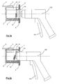
- the gun support 1 essentially consists of a cylindrical receiving body 2 of horizontal axis and a mounting bit 4.
- the receiving body 2 is closed at its rear end by a cover 3 fixed by means of four screws 3a, and is open at its front end so as to define at its inner part a receiving housing 2a of the free end of a dispensing gun 100 represented on the Figures 3a to 3d .
- the receiving body 2 is provided on its outer periphery and at its front end with a thread 2b on which is screwed the mounting end 4.
- This nozzle 4 is equipped with a median circular opening 4a of diameter corresponding to that of the receiving housing 2a and located in the extension of this housing to allow the introduction of the free end of the dispensing gun 100 ( Figures 3a to 3d ).
- the tip 4 is further equipped on its periphery with an external base 4b which allows the attachment of the support 1 to a fuel dispenser apparatus by means of screws not shown in the figures.
- a plate 2c is machined on the outer periphery of the receiving body 2 at the upper part of this body.
- a sensor 5 sensitive to variations in the magnetic field is fixed on the plate 2c by means of two screws 7.
- the sensor 5 is also connected by means of a cable 6 to control members of the fuel transfer between a storage tank and the tank of motor vehicles which are not shown in the figures.
- the receiving body 2 is also equipped at its inner periphery with a longitudinal through groove 2d machined at its upper generatrix.
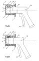
- This longitudinal groove 2d extends outwardly at the mounting end 4 by a fine evacuation notch 4c not shown on the Figures 1 and 2 but visible on Figures 3a to 3d .
- the receiving body 2 is further equipped with a rod 8 inserted into through openings machined at the upper part of this body on either side of the longitudinal groove 2d and held by a nut 8a.
- This rod 8 which extends perpendicularly to the longitudinal groove 2d constitutes a pivot axis for a tab 9a hinged thereto at one of its ends and carrying at its opposite end a housing 9 in which is housed a magnet 10 .
- control members are in standby so as to be able to trigger the transfer of fuel if a user maneuvers the handle 101 of the dispensing gun 100.
- the magnet 10 is located in the immediate vicinity of the sensor 5 below it and is separated from this sensor only by the wall of the receiving body 2 which is very thin at this level given the the machining of the longitudinal groove 2d.
- the senor 5 is sensitive to the presence of the magnet 10 which has been calibrated accordingly and then transmits to the control members via the cable 6 signals of such a nature to put these organs in stop to interrupt any transfer of fuel between the storage tank and the dispensing gun.
- the sensor 5 is then no longer sensitive to the presence of the magnet 10 and the control members are again put on standby so as to trigger the transfer of fuel as soon as the user actuates the handle 101 of the dispensing gun 100 .
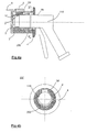
- the receiving housing 4a of the receiving body 2 is equipped at its lower part with an adapter support member 200 extending over its entire length.
- the support 1 is thus adapted to receiving or guiding the free end of a smaller dispensing nozzle 110 to the gun 100 shown in FIGS. Figures 3a to 3d .
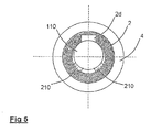
- the one-piece adapter support member 200 is replaced by two elements 210 fixed on either side of the receiving housing 2a.
- the adaptation elements 200, 210 are sized according to the type of gun (shape and dimensions) intended to be accommodated in the receiving body 2 of the support 1.
Landscapes
- Engineering & Computer Science (AREA)
- Mechanical Engineering (AREA)
- General Engineering & Computer Science (AREA)
- Cooling, Air Intake And Gas Exhaust, And Fuel Tank Arrangements In Propulsion Units (AREA)
- Loading And Unloading Of Fuel Tanks Or Ships (AREA)
- Detergent Compositions (AREA)
- Acyclic And Carbocyclic Compounds In Medicinal Compositions (AREA)
- Control Of Motors That Do Not Use Commutators (AREA)
- Filling Or Discharging Of Gas Storage Vessels (AREA)
- Coating Apparatus (AREA)
- Nozzles (AREA)
- Sampling And Sample Adjustment (AREA)
Claims (6)
- Zapfpistolen-Aufnahmevorrichtung für eine Zapfsäule, die in einer Zapfanlage für Flüssiggas-Kraftstoff aufgestellt ist, welche mit Mitteln zur Steuerung des Transports des Kraftstoffs zwischen einem Vorratsbehälter und dem Tank des Kraftfahrzeugs ausgestattet ist, wobei diese Aufnahmevorrichtung Folgendes umfasst:- einen Aufnahmekörper (2), insbesondere verschlossen an einem seiner Enden oder am hinteren Ende durch einen Deckel (3) und offen am gegenüberliegenden oder vorderen Ende, um in seinem Innenbereich einen Aufnahmesitz (2a) für das freie Ende einer Zapfpistole (100) zu bilden,- eine Einbauabdeckung (4), befestigt am Aufnahmekörper (2) im Bereich steines vorderen Endes und versehen mit einer Öffnung (4a), um das freie Ende der Zapfpistole (100) einführen zu können, sowie einer äußeren Stirnfläche (4b), durch die die Aufnahmevorrichtung an der Zapfsäule montiert werden kann, und- Erkennungsmittel, die erkennen können, ob das freie Ende der Zapfpistole (100) im Aufnahmesitz (2a) fehlt oder vorhanden ist und die mit den Steuerungsmitteln verbunden sind, um ihnen Signale, die diesen Zapfpistolenzustand darstellen, zu übermitteln, damit sie im Gegenzug das Starten oder Unterbrechen des Transports des Kraftstoffes auslösen können,dadurch gekennzeichnet, dass
der Aufnahmesitz (2a) in seinem unteren Teil mit wenigstens einem einstückigen Anpassungs-Stützelement (200, 210) versehen ist, das sich auf der gesamten Länge des Aufnahmekörpers (2) erstreckt und die Aufgabe hat, das freie Ende der Zapfpistole bei seinem Einrühren in den Aufnahmesitz zu führen und um seinen Halt in diesem Gehäuse zu ermöglichen. - Zapfpistolen-Aufnahmevorrichtung nach Anspruch 1, dadurch gekennzeichnet, dass die Einbauabdeckung (4) in ihrem inneren Teil eine schmale Evakuierungseinkerbung (4c) aufweist.
- Zapfpistolen-Aufnahmevorrichtung nach einem der Ansprüche 1 und 2, dadurch gekennzeichnet, dass die Erkennungsmittel Folgendes aufweisen:- einen Sensor (5), der auf Veränderungen des Magnetfeldes anspricht, mit den Steuerungsmitteln verbunden und außen am Umfang des Aufnahmekörpers (2) befestigt ist, und- einen Magnet (10), im Aufnahmesitz (2a) beweglich angeordnet zwischen einerseits einer Kraftstoff-Transportstellung, in die er beim Fehlen der Zapfpistole in diesem Sitz automatisch rückgestellt wird, und andererseits einer Abschaltstellung, in die er beim Einführen der Zapfpistole (100) in den Aufnahmesitz (2a) verlagert wird und in der er sich in unmittelbarer Nähe des Sensors (5) befindet, wobei er durch die Umfangswand des Aufnahmekörpers (2) von diesem Sensor getrennt ist, um das Auslösen der Unterbrechung des Kraftstofftransports zu ermöglichen.
- Zapfpistolen-Aufnahmevorrichtung nach Anspruch 3, dadurch gekennzeichnet, dass der Aufnahmekörper (2) in seinem Innenbereich und im Bereich seiner oben liegenden Mantellinie mit einer vorzugsweise ihn durchquerenden Längsnut (2d) verstehen ist, in die der Magnet (10) in seiner Abschaltstellung aufgenommen ist.
- Zapfpistolen-Aufnahmevorrichtung nach einem der Ansprüche 3 und 4, dadurch gekennzeichnet, dass der Magnet (10) in einem durch eine Zunge (9a) verlängerten Gehäuse (9) angeordnet ist, welche an ihrem freien Ende um einen Stift (8) schwenkbar ist, der rechtwinklig zur Längsnut (2d) beidseits dieser Nut am Aufnahmekörper (2) befestigt ist.
- Zapfpistolen-Aufnahmevorrichtung nach den Ansprüchen 2 und 4, dadurch gekennzeichnet, dass die Evakuierungseinkerbung (4c) in der Verlängerung der Längsnut (2d) des Aufnahmekörpers (2) angeordnet ist.
Priority Applications (1)
| Application Number | Priority Date | Filing Date | Title |
|---|---|---|---|
| PL09305820T PL2177474T3 (pl) | 2008-10-06 | 2009-09-08 | Wspornik pistoletu do dystrybutora paliwa typu LPG |
Applications Claiming Priority (1)
| Application Number | Priority Date | Filing Date | Title |
|---|---|---|---|
| FR0856746A FR2936789B1 (fr) | 2008-10-06 | 2008-10-06 | Support de pistolet pour appareil distributeur de carburant de type gpl |
Publications (2)
| Publication Number | Publication Date |
|---|---|
| EP2177474A1 EP2177474A1 (de) | 2010-04-21 |
| EP2177474B1 true EP2177474B1 (de) | 2011-01-19 |
Family
ID=40474184
Family Applications (1)
| Application Number | Title | Priority Date | Filing Date |
|---|---|---|---|
| EP09305820A Active EP2177474B1 (de) | 2008-10-06 | 2009-09-08 | Aufnahmevorrichtung für Flüssiggaszapfpistole |
Country Status (6)
| Country | Link |
|---|---|
| EP (1) | EP2177474B1 (de) |
| AT (1) | ATE496003T1 (de) |
| DE (1) | DE602009000635D1 (de) |
| ES (1) | ES2359044T3 (de) |
| FR (1) | FR2936789B1 (de) |
| PL (1) | PL2177474T3 (de) |
Families Citing this family (2)
| Publication number | Priority date | Publication date | Assignee | Title |
|---|---|---|---|---|
| FR3103186B1 (fr) * | 2019-11-15 | 2021-10-22 | Cryostar Sas | Réceptacle pour connecteur cryogénique |
| FR3144853B1 (fr) * | 2023-01-05 | 2025-03-07 | Air Liquide | Réceptacle pour recevoir un raccord cryogénique |
Family Cites Families (5)
| Publication number | Priority date | Publication date | Assignee | Title |
|---|---|---|---|---|
| DE2807976B2 (de) * | 1978-02-24 | 1980-01-10 | Dresser Europe S.A. Niederlassung Einbeck, 3352 Einbeck | Schutzeinrichtung für eine Kraftstoff-Zapfsäule |
| US5110010A (en) * | 1990-09-21 | 1992-05-05 | Gilbarco, Inc. | Automatic fuel dispenser actuator |
| AU643377B2 (en) * | 1991-04-18 | 1993-11-11 | Gilbarco Aust Limited | Nozzle locking device |
| US6149033A (en) * | 1999-06-24 | 2000-11-21 | Marconi Commerce Systems Inc. | Sensing device for nozzle removal and replacement detection |
| US20050000588A1 (en) * | 2003-03-21 | 2005-01-06 | Webb Michael C. | Dispenser activation method and apparatus |
-
2008
- 2008-10-06 FR FR0856746A patent/FR2936789B1/fr active Active
-
2009
- 2009-09-08 ES ES09305820T patent/ES2359044T3/es active Active
- 2009-09-08 EP EP09305820A patent/EP2177474B1/de active Active
- 2009-09-08 PL PL09305820T patent/PL2177474T3/pl unknown
- 2009-09-08 DE DE602009000635T patent/DE602009000635D1/de active Active
- 2009-09-08 AT AT09305820T patent/ATE496003T1/de not_active IP Right Cessation
Also Published As
| Publication number | Publication date |
|---|---|
| DE602009000635D1 (de) | 2011-03-03 |
| FR2936789B1 (fr) | 2016-07-29 |
| ES2359044T3 (es) | 2011-05-17 |
| EP2177474A1 (de) | 2010-04-21 |
| FR2936789A1 (fr) | 2010-04-09 |
| ATE496003T1 (de) | 2011-02-15 |
| PL2177474T3 (pl) | 2011-06-30 |
Similar Documents
| Publication | Publication Date | Title |
|---|---|---|
| EP1117454B1 (de) | Vorgefüllte injektionsvorrichtung für einmalverwendung | |
| EP2456024B1 (de) | Stromsteckdose mit Verschlussvorrichtung | |
| EP3117136B1 (de) | Ventileinheit für gasbehälter mit druckanzeigender oder betriebszeitanzeigender vorrichtung nahe der oberseite | |
| EP2177474B1 (de) | Aufnahmevorrichtung für Flüssiggaszapfpistole | |
| EP2062610A1 (de) | Vorrichtung zum Aufblasen eines Luftsacks | |
| WO2021093985A1 (fr) | Réceptacle pour connecteur cryogénique | |
| EP2362193A1 (de) | Füllstandsmesser für Flüssigbrennstoff-Zapfgerät und Verfahren, das anlässlich der Verwendung eines solchen Füllstandsmessers eingesetzt wird | |
| EP3365268B1 (de) | Kraftstoffverteiler mit hydraulikraum mit einer additiveinspritzvorrichtung | |
| EP2367581B1 (de) | Verstellbare druckpumpe | |
| EP0770205A1 (de) | Verschlusssystem für ein gefäss und mikrowellenbehandlungsvorrichtung mit einem solchen verschlusssystem | |
| EP2011424A2 (de) | Haushaltsgerät, das einen Arbeitsbehälter mit einer Öffnung umfasst, über die ein abnehmbarer Weghahn angeschlossen werden kann | |
| EP2505110A1 (de) | Reibevorrichtung für Lebensmittel, insbesondere für Käse | |
| FR3042584A1 (fr) | Bloc rdi de distribution de gaz avec dispositif indicateur agence au centre du volant de manœuvre | |
| FR3034293A1 (fr) | Coque amovible pour vaporisateur rechargeable portatif | |
| FR2706313A1 (fr) | Dispositif de protection contre l'incendie de véhicules équipés d'un réservoir de carburant. | |
| EP1953779B1 (de) | Sicherunglasttrennschalter mit Schnellverschlusssicherung | |
| EP0060789B1 (de) | Durchflussabsperrventil | |
| EP3835711B1 (de) | Zündsystem einer raketentreibstoffladung | |
| EP2883577B1 (de) | Zusatzstoffmodul für Feuerlöscher, und mit einem solchen Modul ausgestatteter Feuerlöscher | |
| FR2956655A1 (fr) | Dispositif de securite pour une installation de distribution de carburant volatil ou gazeux | |
| FR2911540A1 (fr) | Systeme d'obturation pour tete de tubulure de remplissage. | |
| FR2632194A1 (fr) | Tete pour extincteur a pression auxiliaire | |
| FR2727955A1 (fr) | Dispositif de coupure automatique d'emplissage de recipient | |
| BE524767A (de) | ||
| CH524106A (fr) | Briquet à gaz |
Legal Events
| Date | Code | Title | Description |
|---|---|---|---|
| PUAI | Public reference made under article 153(3) epc to a published international application that has entered the european phase |
Free format text: ORIGINAL CODE: 0009012 |
|
| AK | Designated contracting states |
Kind code of ref document: A1 Designated state(s): AT BE BG CH CY CZ DE DK EE ES FI FR GB GR HR HU IE IS IT LI LT LU LV MC MK MT NL NO PL PT RO SE SI SK SM TR |
|
| AX | Request for extension of the european patent |
Extension state: AL BA RS |
|
| 17P | Request for examination filed |
Effective date: 20100508 |
|
| GRAP | Despatch of communication of intention to grant a patent |
Free format text: ORIGINAL CODE: EPIDOSNIGR1 |
|
| GRAS | Grant fee paid |
Free format text: ORIGINAL CODE: EPIDOSNIGR3 |
|
| GRAA | (expected) grant |
Free format text: ORIGINAL CODE: 0009210 |
|
| AK | Designated contracting states |
Kind code of ref document: B1 Designated state(s): AT BE BG CH CY CZ DE DK EE ES FI FR GB GR HR HU IE IS IT LI LT LU LV MC MK MT NL NO PL PT RO SE SI SK SM TR |
|
| REG | Reference to a national code |
Ref country code: GB Ref legal event code: FG4D Free format text: NOT ENGLISH |
|
| REG | Reference to a national code |
Ref country code: CH Ref legal event code: EP |
|
| REG | Reference to a national code |
Ref country code: IE Ref legal event code: FG4D Free format text: LANGUAGE OF EP DOCUMENT: FRENCH |
|
| REF | Corresponds to: |
Ref document number: 602009000635 Country of ref document: DE Date of ref document: 20110303 Kind code of ref document: P |
|
| REG | Reference to a national code |
Ref country code: DE Ref legal event code: R096 Ref document number: 602009000635 Country of ref document: DE Effective date: 20110303 |
|
| REG | Reference to a national code |
Ref country code: NL Ref legal event code: T3 |
|
| REG | Reference to a national code |
Ref country code: ES Ref legal event code: FG2A Ref document number: 2359044 Country of ref document: ES Kind code of ref document: T3 Effective date: 20110517 |
|
| LTIE | Lt: invalidation of european patent or patent extension |
Effective date: 20110119 |
|
| REG | Reference to a national code |
Ref country code: PL Ref legal event code: T3 |
|
| PG25 | Lapsed in a contracting state [announced via postgrant information from national office to epo] |
Ref country code: NO Free format text: LAPSE BECAUSE OF FAILURE TO SUBMIT A TRANSLATION OF THE DESCRIPTION OR TO PAY THE FEE WITHIN THE PRESCRIBED TIME-LIMIT Effective date: 20110419 Ref country code: LV Free format text: LAPSE BECAUSE OF FAILURE TO SUBMIT A TRANSLATION OF THE DESCRIPTION OR TO PAY THE FEE WITHIN THE PRESCRIBED TIME-LIMIT Effective date: 20110119 Ref country code: GR Free format text: LAPSE BECAUSE OF FAILURE TO SUBMIT A TRANSLATION OF THE DESCRIPTION OR TO PAY THE FEE WITHIN THE PRESCRIBED TIME-LIMIT Effective date: 20110420 Ref country code: SE Free format text: LAPSE BECAUSE OF FAILURE TO SUBMIT A TRANSLATION OF THE DESCRIPTION OR TO PAY THE FEE WITHIN THE PRESCRIBED TIME-LIMIT Effective date: 20110119 Ref country code: HR Free format text: LAPSE BECAUSE OF FAILURE TO SUBMIT A TRANSLATION OF THE DESCRIPTION OR TO PAY THE FEE WITHIN THE PRESCRIBED TIME-LIMIT Effective date: 20110119 Ref country code: PT Free format text: LAPSE BECAUSE OF FAILURE TO SUBMIT A TRANSLATION OF THE DESCRIPTION OR TO PAY THE FEE WITHIN THE PRESCRIBED TIME-LIMIT Effective date: 20110519 Ref country code: IS Free format text: LAPSE BECAUSE OF FAILURE TO SUBMIT A TRANSLATION OF THE DESCRIPTION OR TO PAY THE FEE WITHIN THE PRESCRIBED TIME-LIMIT Effective date: 20110519 Ref country code: LT Free format text: LAPSE BECAUSE OF FAILURE TO SUBMIT A TRANSLATION OF THE DESCRIPTION OR TO PAY THE FEE WITHIN THE PRESCRIBED TIME-LIMIT Effective date: 20110119 |
|
| REG | Reference to a national code |
Ref country code: IE Ref legal event code: FD4D |
|
| PG25 | Lapsed in a contracting state [announced via postgrant information from national office to epo] |
Ref country code: AT Free format text: LAPSE BECAUSE OF FAILURE TO SUBMIT A TRANSLATION OF THE DESCRIPTION OR TO PAY THE FEE WITHIN THE PRESCRIBED TIME-LIMIT Effective date: 20110119 Ref country code: BG Free format text: LAPSE BECAUSE OF FAILURE TO SUBMIT A TRANSLATION OF THE DESCRIPTION OR TO PAY THE FEE WITHIN THE PRESCRIBED TIME-LIMIT Effective date: 20110419 Ref country code: FI Free format text: LAPSE BECAUSE OF FAILURE TO SUBMIT A TRANSLATION OF THE DESCRIPTION OR TO PAY THE FEE WITHIN THE PRESCRIBED TIME-LIMIT Effective date: 20110119 Ref country code: SI Free format text: LAPSE BECAUSE OF FAILURE TO SUBMIT A TRANSLATION OF THE DESCRIPTION OR TO PAY THE FEE WITHIN THE PRESCRIBED TIME-LIMIT Effective date: 20110119 Ref country code: CY Free format text: LAPSE BECAUSE OF FAILURE TO SUBMIT A TRANSLATION OF THE DESCRIPTION OR TO PAY THE FEE WITHIN THE PRESCRIBED TIME-LIMIT Effective date: 20110119 |
|
| PG25 | Lapsed in a contracting state [announced via postgrant information from national office to epo] |
Ref country code: EE Free format text: LAPSE BECAUSE OF FAILURE TO SUBMIT A TRANSLATION OF THE DESCRIPTION OR TO PAY THE FEE WITHIN THE PRESCRIBED TIME-LIMIT Effective date: 20110119 Ref country code: DK Free format text: LAPSE BECAUSE OF FAILURE TO SUBMIT A TRANSLATION OF THE DESCRIPTION OR TO PAY THE FEE WITHIN THE PRESCRIBED TIME-LIMIT Effective date: 20110119 Ref country code: IE Free format text: LAPSE BECAUSE OF FAILURE TO SUBMIT A TRANSLATION OF THE DESCRIPTION OR TO PAY THE FEE WITHIN THE PRESCRIBED TIME-LIMIT Effective date: 20110119 |
|
| PLBE | No opposition filed within time limit |
Free format text: ORIGINAL CODE: 0009261 |
|
| STAA | Information on the status of an ep patent application or granted ep patent |
Free format text: STATUS: NO OPPOSITION FILED WITHIN TIME LIMIT |
|
| PG25 | Lapsed in a contracting state [announced via postgrant information from national office to epo] |
Ref country code: RO Free format text: LAPSE BECAUSE OF FAILURE TO SUBMIT A TRANSLATION OF THE DESCRIPTION OR TO PAY THE FEE WITHIN THE PRESCRIBED TIME-LIMIT Effective date: 20110119 Ref country code: CZ Free format text: LAPSE BECAUSE OF FAILURE TO SUBMIT A TRANSLATION OF THE DESCRIPTION OR TO PAY THE FEE WITHIN THE PRESCRIBED TIME-LIMIT Effective date: 20110119 Ref country code: SK Free format text: LAPSE BECAUSE OF FAILURE TO SUBMIT A TRANSLATION OF THE DESCRIPTION OR TO PAY THE FEE WITHIN THE PRESCRIBED TIME-LIMIT Effective date: 20110119 |
|
| 26N | No opposition filed |
Effective date: 20111020 |
|
| REG | Reference to a national code |
Ref country code: DE Ref legal event code: R097 Ref document number: 602009000635 Country of ref document: DE Effective date: 20111020 |
|
| PG25 | Lapsed in a contracting state [announced via postgrant information from national office to epo] |
Ref country code: MC Free format text: LAPSE BECAUSE OF NON-PAYMENT OF DUE FEES Effective date: 20110930 |
|
| REG | Reference to a national code |
Ref country code: AT Ref legal event code: MK05 Ref document number: 496003 Country of ref document: AT Kind code of ref document: T Effective date: 20110119 |
|
| PG25 | Lapsed in a contracting state [announced via postgrant information from national office to epo] |
Ref country code: MK Free format text: LAPSE BECAUSE OF FAILURE TO SUBMIT A TRANSLATION OF THE DESCRIPTION OR TO PAY THE FEE WITHIN THE PRESCRIBED TIME-LIMIT Effective date: 20110119 Ref country code: MT Free format text: LAPSE BECAUSE OF FAILURE TO SUBMIT A TRANSLATION OF THE DESCRIPTION OR TO PAY THE FEE WITHIN THE PRESCRIBED TIME-LIMIT Effective date: 20110119 |
|
| PG25 | Lapsed in a contracting state [announced via postgrant information from national office to epo] |
Ref country code: SM Free format text: LAPSE BECAUSE OF FAILURE TO SUBMIT A TRANSLATION OF THE DESCRIPTION OR TO PAY THE FEE WITHIN THE PRESCRIBED TIME-LIMIT Effective date: 20110119 |
|
| PG25 | Lapsed in a contracting state [announced via postgrant information from national office to epo] |
Ref country code: LU Free format text: LAPSE BECAUSE OF NON-PAYMENT OF DUE FEES Effective date: 20110908 |
|
| PG25 | Lapsed in a contracting state [announced via postgrant information from national office to epo] |
Ref country code: TR Free format text: LAPSE BECAUSE OF FAILURE TO SUBMIT A TRANSLATION OF THE DESCRIPTION OR TO PAY THE FEE WITHIN THE PRESCRIBED TIME-LIMIT Effective date: 20110119 |
|
| PG25 | Lapsed in a contracting state [announced via postgrant information from national office to epo] |
Ref country code: HU Free format text: LAPSE BECAUSE OF FAILURE TO SUBMIT A TRANSLATION OF THE DESCRIPTION OR TO PAY THE FEE WITHIN THE PRESCRIBED TIME-LIMIT Effective date: 20110119 |
|
| REG | Reference to a national code |
Ref country code: CH Ref legal event code: PL |
|
| PG25 | Lapsed in a contracting state [announced via postgrant information from national office to epo] |
Ref country code: CH Free format text: LAPSE BECAUSE OF NON-PAYMENT OF DUE FEES Effective date: 20130930 Ref country code: LI Free format text: LAPSE BECAUSE OF NON-PAYMENT OF DUE FEES Effective date: 20130930 |
|
| REG | Reference to a national code |
Ref country code: FR Ref legal event code: PLFP Year of fee payment: 7 |
|
| REG | Reference to a national code |
Ref country code: DE Ref legal event code: R088 Ref document number: 602009000635 Country of ref document: DE |
|
| REG | Reference to a national code |
Ref country code: FR Ref legal event code: CL Name of requester: TOKHEIM UK LTD, GB Effective date: 20160419 |
|
| REG | Reference to a national code |
Ref country code: FR Ref legal event code: PLFP Year of fee payment: 8 |
|
| REG | Reference to a national code |
Ref country code: FR Ref legal event code: PLFP Year of fee payment: 9 |
|
| REG | Reference to a national code |
Ref country code: FR Ref legal event code: PLFP Year of fee payment: 10 |
|
| PGFP | Annual fee paid to national office [announced via postgrant information from national office to epo] |
Ref country code: NL Payment date: 20200926 Year of fee payment: 12 Ref country code: GB Payment date: 20200928 Year of fee payment: 12 |
|
| PGFP | Annual fee paid to national office [announced via postgrant information from national office to epo] |
Ref country code: BE Payment date: 20200928 Year of fee payment: 12 Ref country code: PL Payment date: 20200819 Year of fee payment: 12 |
|
| PGFP | Annual fee paid to national office [announced via postgrant information from national office to epo] |
Ref country code: IT Payment date: 20200923 Year of fee payment: 12 Ref country code: ES Payment date: 20201001 Year of fee payment: 12 |
|
| REG | Reference to a national code |
Ref country code: NL Ref legal event code: MM Effective date: 20211001 |
|
| REG | Reference to a national code |
Ref country code: BE Ref legal event code: MM Effective date: 20210930 |
|
| GBPC | Gb: european patent ceased through non-payment of renewal fee |
Effective date: 20210908 |
|
| PG25 | Lapsed in a contracting state [announced via postgrant information from national office to epo] |
Ref country code: NL Free format text: LAPSE BECAUSE OF NON-PAYMENT OF DUE FEES Effective date: 20211001 |
|
| PG25 | Lapsed in a contracting state [announced via postgrant information from national office to epo] |
Ref country code: GB Free format text: LAPSE BECAUSE OF NON-PAYMENT OF DUE FEES Effective date: 20210908 Ref country code: BE Free format text: LAPSE BECAUSE OF NON-PAYMENT OF DUE FEES Effective date: 20210930 |
|
| PG25 | Lapsed in a contracting state [announced via postgrant information from national office to epo] |
Ref country code: IT Free format text: LAPSE BECAUSE OF NON-PAYMENT OF DUE FEES Effective date: 20210908 |
|
| REG | Reference to a national code |
Ref country code: ES Ref legal event code: FD2A Effective date: 20221107 |
|
| PG25 | Lapsed in a contracting state [announced via postgrant information from national office to epo] |
Ref country code: ES Free format text: LAPSE BECAUSE OF NON-PAYMENT OF DUE FEES Effective date: 20210909 |
|
| P01 | Opt-out of the competence of the unified patent court (upc) registered |
Effective date: 20230529 |
|
| PG25 | Lapsed in a contracting state [announced via postgrant information from national office to epo] |
Ref country code: PL Free format text: LAPSE BECAUSE OF NON-PAYMENT OF DUE FEES Effective date: 20210908 |
|
| PGFP | Annual fee paid to national office [announced via postgrant information from national office to epo] |
Ref country code: DE Payment date: 20240910 Year of fee payment: 16 |
|
| PGFP | Annual fee paid to national office [announced via postgrant information from national office to epo] |
Ref country code: FR Payment date: 20240909 Year of fee payment: 16 |