EP2177247A1 - Badminton racket and manufacturing method of badminton racket - Google Patents
Badminton racket and manufacturing method of badminton racket Download PDFInfo
- Publication number
- EP2177247A1 EP2177247A1 EP08791805A EP08791805A EP2177247A1 EP 2177247 A1 EP2177247 A1 EP 2177247A1 EP 08791805 A EP08791805 A EP 08791805A EP 08791805 A EP08791805 A EP 08791805A EP 2177247 A1 EP2177247 A1 EP 2177247A1
- Authority
- EP
- European Patent Office
- Prior art keywords
- frame
- joint
- shaft
- resin
- badminton racket
- Prior art date
- Legal status (The legal status is an assumption and is not a legal conclusion. Google has not performed a legal analysis and makes no representation as to the accuracy of the status listed.)
- Granted
Links
- 238000004519 manufacturing process Methods 0.000 title claims abstract description 17
- 229920005989 resin Polymers 0.000 claims abstract description 125
- 239000011347 resin Substances 0.000 claims abstract description 125
- 238000000034 method Methods 0.000 claims abstract description 12
- 238000005304 joining Methods 0.000 claims description 18
- 238000010438 heat treatment Methods 0.000 claims description 12
- 229920005992 thermoplastic resin Polymers 0.000 claims description 11
- 239000004088 foaming agent Substances 0.000 claims description 10
- 238000005096 rolling process Methods 0.000 claims description 2
- 230000002093 peripheral effect Effects 0.000 description 10
- OKTJSMMVPCPJKN-UHFFFAOYSA-N Carbon Chemical compound [C] OKTJSMMVPCPJKN-UHFFFAOYSA-N 0.000 description 9
- 229910052799 carbon Inorganic materials 0.000 description 9
- 239000003795 chemical substances by application Substances 0.000 description 4
- 239000003822 epoxy resin Substances 0.000 description 4
- 229920000647 polyepoxide Polymers 0.000 description 4
- 229920002430 Fibre-reinforced plastic Polymers 0.000 description 3
- 239000000853 adhesive Substances 0.000 description 3
- 230000001070 adhesive effect Effects 0.000 description 3
- 239000011151 fibre-reinforced plastic Substances 0.000 description 3
- 239000003094 microcapsule Substances 0.000 description 3
- 150000002825 nitriles Chemical class 0.000 description 3
- 229910000838 Al alloy Inorganic materials 0.000 description 2
- 229920000049 Carbon (fiber) Polymers 0.000 description 2
- 239000004917 carbon fiber Substances 0.000 description 2
- 239000003365 glass fiber Substances 0.000 description 2
- 239000007788 liquid Substances 0.000 description 2
- VNWKTOKETHGBQD-UHFFFAOYSA-N methane Chemical compound C VNWKTOKETHGBQD-UHFFFAOYSA-N 0.000 description 2
- 230000003014 reinforcing effect Effects 0.000 description 2
- 239000004677 Nylon Substances 0.000 description 1
- 238000005452 bending Methods 0.000 description 1
- 238000010586 diagram Methods 0.000 description 1
- 238000001035 drying Methods 0.000 description 1
- 230000000694 effects Effects 0.000 description 1
- -1 for example Polymers 0.000 description 1
- 229910052751 metal Inorganic materials 0.000 description 1
- 239000002184 metal Substances 0.000 description 1
- 230000004048 modification Effects 0.000 description 1
- 238000012986 modification Methods 0.000 description 1
- 229920001778 nylon Polymers 0.000 description 1
- 229920000768 polyamine Polymers 0.000 description 1
- 230000002787 reinforcement Effects 0.000 description 1
- 238000002791 soaking Methods 0.000 description 1
Images

Classifications
-
- A—HUMAN NECESSITIES
- A63—SPORTS; GAMES; AMUSEMENTS
- A63B—APPARATUS FOR PHYSICAL TRAINING, GYMNASTICS, SWIMMING, CLIMBING, OR FENCING; BALL GAMES; TRAINING EQUIPMENT
- A63B49/00—Stringed rackets, e.g. for tennis
- A63B49/02—Frames
- A63B49/03—Frames characterised by throat sections, i.e. sections or elements between the head and the shaft
- A63B49/032—T-shaped connection elements
-
- A—HUMAN NECESSITIES
- A63—SPORTS; GAMES; AMUSEMENTS
- A63B—APPARATUS FOR PHYSICAL TRAINING, GYMNASTICS, SWIMMING, CLIMBING, OR FENCING; BALL GAMES; TRAINING EQUIPMENT
- A63B2209/00—Characteristics of used materials
- A63B2209/02—Characteristics of used materials with reinforcing fibres, e.g. carbon, polyamide fibres
Definitions
- the present invention relates to a badminton racket provided with a joint reaching inside a frame and inside a shaft and a manufacturing method of a badminton racket thereof.
- a badminton racket with a hollow frame formed in an oval shape and a hollow shaft that are joined provided with a T-shaped joint reaching inside the frame and inside the shaft.
- a hollow member for forming the frame is bent circularly, and the joint with liquid adhesive is inserted to reach between both end portions and one end portion of the shaft.
- a fiber reinforced plastic resin tape is wound on an outer periphery of a joining portion of the frame and the shaft for reinforcement, and then put in a die and heated and formed (refer to for example, Japanese Patent No. 2004-65862 ). Therefore, it is preferable that an inner diameter of the frame is formed sufficiently larger that an outer diameter of the joint so that the joint can be easily inserted into the hollow frame.
- the present invention was made in view of the above described problem, and its object is to provide a badminton racket that is strong in respect to impact and twist and high in surface stability and a manufacturing method of such a badminton racket.
- a badminton racket is characterized by including:
- a badminton racket of the present invention since an expandable resin is placed in between the joint, that is installed reaching inside the frame and the shaft, and the frame, a gap between the joint and the frame is not formed easily, and it is possible to realize a badminton racket with high surface stability. Since the expandable resin that is placed in between the joint and the frame is expanded expandable resin, by providing the expandable resin in a state before it is expanded in between the joint and the frame, and then expanding it, the expandable resin can be made to sufficiently reach all over the gap between the joint and the frame. Therefore it is possible to realize a badminton racket that is stronger in respect to impact and twist and that is high in surface stability, and to improve the direction and speed of the shuttle that was hit.
- the joint is made of a resin.
- a badminton racket manufacturing method includes:
- the expandable resin placed inside the resin sheet tube and the expandable resin placed on an outer periphery of the joint and installed inside the frame are both expanded by heat, by installing the joint inside the both end portions of the resin sheet tube bent circularly and butted against each other and inside the shaft, and setting them in the die and heating them, it is possible to expand the expandable resin inside the frame including the joining portion with the shaft and to fill the inside of the frame.
- a peripheral portion of the resin sheet tube that forms the frame is formed of a thermoplastic resin sheet, so that the peripheral portion of the resin sheet tube deforms by heating the die.
- the resin sheet tube is spread out along the die, and it is possible to form the frame in a desired shape along the die.
- the expandable resin expands in the joining portion of the frame and the shaft, so that it is possible for the overall frame to be formed in a desired shape along the die and also to join the frame and the shaft without forming a gap between the frame and the joint.
- the expandable resin has a resin and a foaming agent that expands when heated.
- the expandable resin has a foaming agent that expands by heating, it is possible to more surely make the resin expand by heating, and further by the foaming agent expanding it is possible to easily make the resin reach all over in between the frame and the joint without a gap. Therefore, by placing the expandable resin that is in a non expanded state in between the joint and the frame and then heating it, it is possible to easily fill the gap between the joint and the frame with the expandable resin by expanding the foaming agent.
- the present invention it is possible to provide a badminton racket that is strong in respect to impact and twist and that is high in surface stability and a manufacturing method of the badminton racket thereof.
- Fig. 1 shows a front view of a badminton racket according to the present invention.
- the badminton racket 10 includes a frame 1 formed circularly when seen externally, a shaft 2 that is joined to the frame 1 at one end, and a grip 3 provided at another end portion side of the shaft 2.
- Fig. 2 is a sectional view showing a joining portion of the frame and the shaft.
- the joining portion of the frame 1 and the shaft 2 is installed with a joint 4 that reaches inside the frame 1 and inside the shaft 2, and is reinforced with a reinforcing section 7 that covers a boundary section of the frame and the shaft from the outside
- the frame 1 is a hollow body made of a fiber reinforced plastic mainly composed of carbon fiber and has an expandable resin 5 inside. Further, the shaft 2 is also a hollow body made of the fiber reinforced plastic with mainly carbon fiber, but it is hollow inside.
- the joint 4 is made of a metallic member such as for example, an aluminum alloy.
- the joint 4 includes a to-be-frame installed portion 4a that is installed in the circular frame 1 and is slightly curved, and a to-be-shaft installed portion 4b that is provided approximately vertically to the to-be-frame installed portion 4a from approximately the center in the longitudinal direction of the to-be-frame installed portion 4a in an approximately T-shape.
- a sectional shape of the to-be-frame installed portion 4a is an oval shape that is long and flat in the front and back surface of a hitting surface of the badminton racket 10, similar to the sectional shape of the frame 1.
- a sectional shape of the to-be-shaft installed portion 4b is the same shape as the sectional shape of the shaft 2.
- An outer diameter of the to-be-frame installed portion 4a is formed smaller than an inner diameter of the frame 1 and an outer diameter of the to-be-shaft installedportion 4b is formed smaller than an inner diameter of the shaft 2.
- the expandable resin 6 is placed in between the inside of the frame 1 and the to-be-frame installed portion 4a, and the expandable resin 6 fills in between an inner peripheral surface of the frame 1 and the outer peripheral surface of the to-be-frame installed portion 4a.
- the expandable resin 6 is an expandable resin that has mixed together an epoxy resin elastic adhesive, that is made of mainly an epoxy resin intermediate and a deformed resin family polyamine that is a curing agent, and nitrile thermal expansion microcapsules that are foaming agents, and the resin is in an expanded state.
- the expandable resin is mixed with approximately 10% to 15% of the nitrile thermal expansion microcapsules.
- the expandable resin 6 is placed in between the joint 4, that is installed reaching inside both the frame 1 and the shaft 2, and the frame 1, so that a gap is not formed easily in between the frame 1 and the joint 4, and it is possible to realize the badminton racket 10 with a high surface stability.
- the resin placed in between the frame 1 and the joint 4 is expandable resin, it is possible to make the expandable resin 6 sufficiently spread all over the gap between the frame 1 and the joint 4 by placing the expandable resin that is in an unexpanded state in between the frame 1 and the joint 4 and then expanding it. Therefore, it is possible to realize the badminton racket 10 that is strong in respect to impact and twisting and that has high surface stability, and to improve the direction and speed of the shuttle that is hit.
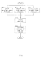
- Fig. 3 is a diagram showing a manufacturing method of a badminton racket. As shown in Fig. 3 , first, carbon pre-pregs are layered concentrically as a plurality of thermoplastic resin sheets, and heated, and a hollow body to be the shaft 2 of the badminton racket 10 is manufactured in advance (shaft manufacturing process: S031).
- the T-shaped joint 4 made of aluminum alloy is placed with an expandable resin 6a that expands when heated on an outer periphery of the to-be-frame installed portion 4a (expandable resin placing process:S021).
- the expandable resin 6a which expands when heated may be coated by soaking the to-be-frame installed portion 4a of the joint 4 in a liquid thermally foamable resin and drying it, or a thermally foamable resin that is formed in a sheet shape of approximately 0.3mm thick may be wrapped in advance excluding a portion that connects the to-be-frame installed portion 4a and the to-be-shaft installed portion 4b,
- thermoplastic resin sheets are layered, and on its inner side the expandable resin 5a, that expands when heated, is placed to form a resin sheet tube wrapped cylindrically (resin sheet tube forming process: S011).
- the expandable resin 5a that is placed on the inner side of the carbon pre-preg is stopped sufficiently inside from an endof the resin sheet tube so that the expandable resin 5 does not project out from the end of the resin sheet tube at the time the expandable resin 5a is expanded.
- a band-shaped carbon pre-preg is wrapped over both end portions of the resin sheet tube at the joining portion of the frame 1 and the shaft 2.
- the portion at which the band-shaped carbon pre-preg is wrapped becomes a reinforced portion 7 in the joining portion of the frame 1 and the shaft 2.
- the layered carbon pre-preg sheets of the resin sheet tube that forms the frame 1 are heated and deform, and at that time, the expandable resins 5a, 6a placed inside expand and spread out outwardly the layered carbon pre-preg sheets of the resin sheet tube and pushes the outer peripheral surface of the carbon pre-preg sheets against the die. Therefore, the deformed resin sheet tube is formed into a smooth shape along the die without any projections and depressions on the surface.
- the expandable resin 6a placed in the to-be-frame installed portion 4a of the joint 4 expands and spreads out outwardly the carbon pre-peg sheets at the end portion of the resin sheet tube and pushes the outer peripheral surface against the die. Therefore, the joining portion of the frame 1 and the shaft 2 is also formed into a smooth shape with out any depressions and projections on the surface similar to other portions of the frame 1.
- the expandable resin 6a placed in the to-be-frame installed portion 4a of the joint 4 expands, fills the gap between the inner surface of the frame 1 and the joint 4 and hardens, and integrates with the shaft 2.
- the expandable resin 5a placed inside the resin sheet tube and the expandable resin 6a placed on an outer periphery of the joint 4 and installed inside the frame 1 both expand by heat. Therefore, by installing the joint 4 inside the both end portions of the resin sheet tube bent circularly and butted against each other and inside the shaft 2, and setting the frame, the shaft and the joint in the die and heating them, it is possible to expand the expandable resins 5a, 6a inside the frame 1 including the joining portion with the shaft 2.
- the outer peripheral portion of the resin sheet tube that forms the frame 1 is formed of a thermoplastic resin sheet, so that the outer peripheral portion of the resin sheet tube deforms when the die is heated.
- the expandable resins 5a, 6 placed inside the resin sheet tube and on the outer periphery of the joint 4 expanding the resin sheet tube is spread out along the die, and the frame 1 can be formed into a desired shape.
- the expandable resin 6a expands in the joining portion of the frame 1 and the shaft 2, it is possible to form the overall frame 1 along the die into a desired shape, and to join the frame 1 and the shaft 2 without forming any gap between the frame 1 and the joint 4.
- the expandable resin 6 placed in between the frame 1 and the joint 4 has a foaming agent that expands when heated, it is possible to make the resin easily spread out between the frame 1 and the joint 4 with the foaming agent that has expanded when heated.
- the expandable resin 6a in an unexpanded state between the joint 4 and the frame 1 and heating them, it is possible to easily fill the gap between the joint 4 and the frame 1 by expanding the foaming agent.
- a badminton racket 10 that is outstanding in manufacturability.
- the frame 1 and the joint 4 and the hardened expandable resin 6 integrate, and it becomes possible to provide a badminton racket 10 with higher surface stability.
- the joint 4 is made of metal, but it may be made of resin or the like.
- a joint made of resin a thermoplastic resin, for example, nylon and the like is applicable.
- a resin that is thermoplastic resin mixed with glass fiber is more preferable. With the resin that is thermoplastic resin mixed with glass fiber, it is possible to make the joint lighter and to increase its strength.
- the expandable resin there is given a resin mixed with an epoxy resin elastic adhesive made of an epoxy resin intermediate that is a main component and a deformed resin familypolyamine that is a curing agent, and nitrile thermal expanding microcapsules that is a foaming agent, but it is not limited to this.
Abstract
Description
- The present invention relates to a badminton racket provided with a joint reaching inside a frame and inside a shaft and a manufacturing method of a badminton racket thereof.
- In prior art, as a badminton racket, there is known a badminton racket with a hollow frame formed in an oval shape and a hollow shaft that are joined provided with a T-shaped joint reaching inside the frame and inside the shaft. In such a badminton racket, firstly, a hollow member for forming the frame is bent circularly, and the joint with liquid adhesive is inserted to reach between both end portions and one end portion of the shaft. Then, a fiber reinforced plastic resin tape is wound on an outer periphery of a joining portion of the frame and the shaft for reinforcement, and then put in a die and heated and formed (refer to for example, Japanese Patent No.
2004-65862 - However, when an inner diameter of the frame is formed sufficiently larger than an outer diameter of the joint, there is a possibility that a gap is formed in between an inner peripheral surface of the frame and an outer peripheral surface of the joint at the time the frame and the shaft are joined. There was a problem that a joining portion of a frame and a shaft with a gap formed inside is weak with respect to impact and twist when hitting a shuttle and low in surface stability, therefore the flight direction of the shuttle that was hit could not be easily decided.
- The present invention was made in view of the above described problem, and its object is to provide a badminton racket that is strong in respect to impact and twist and high in surface stability and a manufacturing method of such a badminton racket.
- In order to achieve the above described object, a badminton racket according to the invention is characterized by including:
- a frame formed circularly;
- a shaft joined to the frame;
- a joint installed reaching inside the frame and the shaft at a joint portion of the frame and the shaft; and
- an expandable resin placed between the joint and the frame.
- According to a badminton racket of the present invention, since an expandable resin is placed in between the joint, that is installed reaching inside the frame and the shaft, and the frame, a gap between the joint and the frame is not formed easily, and it is possible to realize a badminton racket with high surface stability. Since the expandable resin that is placed in between the joint and the frame is expanded expandable resin, by providing the expandable resin in a state before it is expanded in between the joint and the frame, and then expanding it, the expandable resin can be made to sufficiently reach all over the gap between the joint and the frame. Therefore it is possible to realize a badminton racket that is stronger in respect to impact and twist and that is high in surface stability, and to improve the direction and speed of the shuttle that was hit.
- In such a badminton racket, it is preferable that the joint is made of a resin.
- According to such a badminton racket, since the joint installed reaching inside the frame and the shaft is made of a resin, it is possible to make the racket lighter than, for example, in the case where a metallic joint is used.
- Further, a badminton racket manufacturing method includes:
- a resin sheet tube forming process that forms a resin sheet tube by placing an expandable resin that expands when heated on an inner side of a thermoplastic resin sheet and rolling the thermoplastic resin sheet into a cylindrical shape;
- an expandable resin placing process that places an expandable resin that expands when heated to an outer periphery of a portion of a joint,
the joint being to be installed to reach inside the frame formed with the resin sheet tube and inside a shaft,
the portion being to be installed in the frame; and - a joining process that joins the frame and the shaft by
installing the joint placed with the expandable resin inside both end portions of the resin sheet tube, bent circularly and butted against each other, and the shaft, and
setting the frame, the shaft and the joint in a die, and then heating the frame, the shaft and the joint. - According to such a badminton racket manufacturing method, since the expandable resin placed inside the resin sheet tube and the expandable resin placed on an outer periphery of the joint and installed inside the frame are both expanded by heat, by installing the joint inside the both end portions of the resin sheet tube bent circularly and butted against each other and inside the shaft, and setting them in the die and heating them, it is possible to expand the expandable resin inside the frame including the joining portion with the shaft and to fill the inside of the frame. A peripheral portion of the resin sheet tube that forms the frame is formed of a thermoplastic resin sheet, so that the peripheral portion of the resin sheet tube deforms by heating the die. Thus, by the expandable resin placed inside the resin sheet tube and on the outer periphery of the joint expanding, the resin sheet tube is spread out along the die, and it is possible to form the frame in a desired shape along the die. The expandable resin expands in the joining portion of the frame and the shaft, so that it is possible for the overall frame to be formed in a desired shape along the die and also to join the frame and the shaft without forming a gap between the frame and the joint. Thus, just by setting the resin sheet tube, the shaft, and the joint placed with the expandable resin on the outer periphery in the die and heating it, it is possible to easily manufacture a badminton racket with a higher surface stability.
- Regarding the badminton racket manufacturing method, it is preferable that the expandable resin has a resin and a foaming agent that expands when heated.
- According to such a badminton racket, since the expandable resin has a foaming agent that expands by heating, it is possible to more surely make the resin expand by heating, and further by the foaming agent expanding it is possible to easily make the resin reach all over in between the frame and the joint without a gap. Therefore, by placing the expandable resin that is in a non expanded state in between the joint and the frame and then heating it, it is possible to easily fill the gap between the joint and the frame with the expandable resin by expanding the foaming agent.
- According to the present invention, it is possible to provide a badminton racket that is strong in respect to impact and twist and that is high in surface stability and a manufacturing method of the badminton racket thereof.
- The present application claims priority from Japanese Patent Application No.
2007-201172 filed on August 1, 2007
Features and obj ects of the present invention other than ones stated above will be apparent from the following detailed description with reference to the drawings attached herein. -
-
Fig. 1 is an external view of a badminton racket according to the present invention. -
Fig. 2 is a partial sectional view showing a joining portion of the frame and the shaft of the badminton racket according to the present invention. -
Fig. 3 is a view explaining a manufacturing method of the badminton racket according to the present invention. -
- 1
- frame, 2 shaft, 3 grip, 4 joint,
to-be-frame installed portion 4a,
to-be-shaft installedportion 4b, - 5
- expandable resin, 5a expandable resin,
- 6
- expandable resin, 6a expandable resin,
- 7
- reinforcing portion, 10 badminton racket
- The preferred embodiment of the present invention will be described hereunder with reference to the appended drawings.
-
Fig. 1 shows a front view of a badminton racket according to the present invention. As shown inFig. 1 , thebadminton racket 10 includes a frame 1 formed circularly when seen externally, ashaft 2 that is joined to the frame 1 at one end, and agrip 3 provided at another end portion side of theshaft 2. -
Fig. 2 is a sectional view showing a joining portion of the frame and the shaft. As shown inFig. 2 , the joining portion of the frame 1 and theshaft 2 is installed with a joint 4 that reaches inside the frame 1 and inside theshaft 2, and is reinforced with a reinforcingsection 7 that covers a boundary section of the frame and the shaft from the outside - The frame 1 is a hollow body made of a fiber reinforced plastic mainly composed of carbon fiber and has an
expandable resin 5 inside. Further, theshaft 2 is also a hollow body made of the fiber reinforced plastic with mainly carbon fiber, but it is hollow inside. The joint 4 is made of a metallic member such as for example, an aluminum alloy. - The joint 4 includes a to-be-frame installed portion 4a that is installed in the circular frame 1 and is slightly curved, and a to-be-shaft installed
portion 4b that is provided approximately vertically to the to-be-frame installed portion 4a from approximately the center in the longitudinal direction of the to-be-frame installed portion 4a in an approximately T-shape. A sectional shape of the to-be-frame installed portion 4a is an oval shape that is long and flat in the front and back surface of a hitting surface of thebadminton racket 10, similar to the sectional shape of the frame 1. A sectional shape of the to-be-shaft installedportion 4b is the same shape as the sectional shape of theshaft 2. - An outer diameter of the to-be-frame installed portion 4a is formed smaller than an inner diameter of the frame 1 and an outer diameter of the to-
be-shaft installedportion 4b is formed smaller than an inner diameter of theshaft 2. - The
expandable resin 6 is placed in between the inside of the frame 1 and the to-be-frame installed portion 4a, and theexpandable resin 6 fills in between an inner peripheral surface of the frame 1 and the outer peripheral surface of the to-be-frame installed portion 4a. - The
expandable resin 6 is an expandable resin that has mixed together an epoxy resin elastic adhesive, that is made of mainly an epoxy resin intermediate and a deformed resin family polyamine that is a curing agent, and nitrile thermal expansion microcapsules that are foaming agents, and the resin is in an expanded state. The expandable resin is mixed with approximately 10% to 15% of the nitrile thermal expansion microcapsules. - According to the
badminton racket 10 in this embodiment, theexpandable resin 6 is placed in between the joint 4, that is installed reaching inside both the frame 1 and theshaft 2, and the frame 1, so that a gap is not formed easily in between the frame 1 and the joint 4, and it is possible to realize thebadminton racket 10 with a high surface stability. In particular, since the resin placed in between the frame 1 and the joint 4 is expandable resin, it is possible to make theexpandable resin 6 sufficiently spread all over the gap between the frame 1 and the joint 4 by placing the expandable resin that is in an unexpanded state in between the frame 1 and the joint 4 and then expanding it. Therefore, it is possible to realize thebadminton racket 10 that is strong in respect to impact and twisting and that has high surface stability, and to improve the direction and speed of the shuttle that is hit. -
Fig. 3 is a diagram showing a manufacturing method of a badminton racket.
As shown inFig. 3 , first, carbon pre-pregs are layered concentrically as a plurality of thermoplastic resin sheets, and heated, and a hollow body to be theshaft 2 of thebadminton racket 10 is manufactured in advance (shaft manufacturing process: S031). - Further, the T-shaped joint 4 made of aluminum alloy is placed with an
expandable resin 6a that expands when heated on an outer periphery of the to-be-frame installed portion 4a (expandable resin placing process:S021). Theexpandable resin 6a which expands when heated may be coated by soaking the to-be-frame installed portion 4a of the joint 4 in a liquid thermally foamable resin and drying it, or a thermally foamable resin that is formed in a sheet shape of approximately 0.3mm thick may be wrapped in advance excluding a portion that connects the to-be-frame installed portion 4a and the to-be-shaft installedportion 4b, - Next, a plurality of carbon pre-pregs as thermoplastic resin sheets are layered, and on its inner side the
expandable resin 5a, that expands when heated, is placed to form a resin sheet tube wrapped cylindrically (resin sheet tube forming process: S011). Here, theexpandable resin 5a that is placed on the inner side of the carbon pre-preg is stopped sufficiently inside from an endof the resin sheet tube so that theexpandable resin 5 does not project out from the end of the resin sheet tube at the time theexpandable resin 5a is expanded. - Then, after installing the joint 4 that is placed with the
expandable resin 6a reaching inside both end portions, that are butted by bending the resin sheet tube circularly, and theshaft 2 manufactured in advance, and setting them in a die, they are heated and the frame 1 and theshaft 2 are joined (joining process: S012). A portion in which theexpandable resin 5a is not placed at both end portions of the resin sheet tube bent circularly and butted is installed with the to-be-frame installed portion 4a of the joint 4 placed with theexpandable resin 6a, the to-be-shaft installedportion 4b is inserted into theshaft 2, and a front end of theshaft 2 is abutted against the to-be-frame installed portion 4a. Further, before the joint that is installed inside the frame 1 and theshaft 2 is placed in the die, a band-shaped carbon pre-preg is wrapped over both end portions of the resin sheet tube at the joining portion of the frame 1 and theshaft 2. The portion at which the band-shaped carbon pre-preg is wrapped becomes a reinforcedportion 7 in the joining portion of the frame 1 and theshaft 2. - In the joining process (S012), the layered carbon pre-preg sheets of the resin sheet tube that forms the frame 1 are heated and deform, and at that time, the
expandable resins shaft 2, theexpandable resin 6a placed in the to-be-frame installed portion 4a of the joint 4 expands and spreads out outwardly the carbon pre-peg sheets at the end portion of the resin sheet tube and pushes the outer peripheral surface against the die. Therefore, the joining portion of the frame 1 and theshaft 2 is also formed into a smooth shape with out any depressions and projections on the surface similar to other portions of the frame 1. Further, at the joining portion of the frame 1 and theshaft 2, theexpandable resin 6a placed in the to-be-frame installed portion 4a of the joint 4 expands, fills the gap between the inner surface of the frame 1 and the joint 4 and hardens, and integrates with theshaft 2. - Thereafter, holes for stringing the frame 1 are formed and coated, and the
grip 3 is attached to complete the badminton racket 10 (attaching process of the grip and the like: S013). - According to a manufacturing method of the
badminton racket 10 of this embodiment, theexpandable resin 5a placed inside the resin sheet tube and theexpandable resin 6a placed on an outer periphery of the joint 4 and installed inside the frame 1 both expand by heat. Therefore, by installing the joint 4 inside the both end portions of the resin sheet tube bent circularly and butted against each other and inside theshaft 2, and setting the frame, the shaft and the joint in the die and heating them, it is possible to expand theexpandable resins shaft 2. Here, the outer peripheral portion of the resin sheet tube that forms the frame 1 is formed of a thermoplastic resin sheet, so that the outer peripheral portion of the resin sheet tube deforms when the die is heated. Thus, by theexpandable resins expandable resin 6a expands in the joining portion of the frame 1 and theshaft 2, it is possible to form the overall frame 1 along the die into a desired shape, and to join the frame 1 and theshaft 2 without forming any gap between the frame 1 and the joint 4. Thus, it is possible to easily manufacture abadminton racket 10 with higher surface stability merely by setting the resin sheet tube, theshaft 2, and the joint 4 placed with theexpandable resin 6a on the outer periphery and heating them. - Further, since the
expandable resin 6 placed in between the frame 1 and the joint 4 has a foaming agent that expands when heated, it is possible to make the resin easily spread out between the frame 1 and the joint 4 with the foaming agent that has expanded when heated. Thus, by placing theexpandable resin 6a in an unexpanded state between the joint 4 and the frame 1 and heating them, it is possible to easily fill the gap between the joint 4 and the frame 1 by expanding the foaming agent. Thus, it is possible to realize abadminton racket 10 that is outstanding in manufacturability. - Further, by heating the forming agent expands and the resin inside the
expandable resin 6a hardens due to a curing agent, so that it is possible to spread out without any gap theexpandable resin 6a between the frame 1 and the joint 4 and to harden it. Thus, the frame 1 and the joint 4 and the hardenedexpandable resin 6 integrate, and it becomes possible to provide abadminton racket 10 with higher surface stability. - In the above embodiment, the joint 4 is made of metal, but it may be made of resin or the like. As a joint made of resin, a thermoplastic resin, for example, nylon and the like is applicable. Thus, if the joint is made of a resin, it is possible to make the joint lighter than in the case of using a metallic joint. Further, a resin that is thermoplastic resin mixed with glass fiber is more preferable. With the resin that is thermoplastic resin mixed with glass fiber, it is possible to make the joint lighter and to increase its strength.
- Further, in the above embodiment, as an example of the expandable resin, there is given a resin mixed with an epoxy resin elastic adhesive made of an epoxy resin intermediate that is a main component and a deformed resin familypolyamine that is a curing agent, and nitrile thermal expanding microcapsules that is a foaming agent, but it is not limited to this.
- The above embodiment is described with the
badminton racket 10 that is not strung with strings, but abadminton racket 10 strung with strings is also included. - not that, the above-described embodiment is for a better understanding of the present invention and is not for limiting interpretation of the invention. Various changes and modification can be made without departing from the spirit and scope of the invention, and its equivalents are included within the scope of the present invention.
Claims (4)
- A badminton racket comprising:a frame formed circularly;a shaft joined to the frame;a joint installed reaching inside the frame and the shaft at a joint portion of the frame and the shaft; andan expandable resin placed between the joint and the frame.
- A badminton racket as claimed in claim 1 characterized in that the joint is made of a resin.
- A badminton racket manufacturing method comprising:a resin sheet tube forming process that forms a resin sheet tube by placing an expandable resin that expands when heated on an inner side of a thermoplastic resin sheet and rolling the thermoplastic resin sheet into a cylindrical shape;an expandable resin placing process that places an expandable resin that expands when heated to an outer periphery of a portion of a joint,
the joint being to be installed to reach inside the frame formed with the resin sheet tube and inside a shaft,
the portion being to be installed in the frame; anda joining process that joins the frame and the shaft by
installing the joint placed with the expandable resin inside both end portions of the resin sheet tube, bent circularly and butted against each other, and the shaft, and
setting the frame, the shaft and the joint in a die, and then heating the frame, the shaft and the joint. - A badminton racket manufacturing method according to claim 3, characterized in that
the expandable resin has a resin and a foaming agent that expands when heated.
Applications Claiming Priority (2)
| Application Number | Priority Date | Filing Date | Title |
|---|---|---|---|
| JP2007201172A JP5281767B2 (en) | 2007-08-01 | 2007-08-01 | Badminton racket manufacturing method |
| PCT/JP2008/063570 WO2009017112A1 (en) | 2007-08-01 | 2008-07-29 | Badminton racket and manufacturing method of badminton racket |
Publications (3)
| Publication Number | Publication Date |
|---|---|
| EP2177247A1 true EP2177247A1 (en) | 2010-04-21 |
| EP2177247A4 EP2177247A4 (en) | 2012-11-07 |
| EP2177247B1 EP2177247B1 (en) | 2018-03-07 |
Family
ID=40304342
Family Applications (1)
| Application Number | Title | Priority Date | Filing Date |
|---|---|---|---|
| EP08791805.8A Active EP2177247B1 (en) | 2007-08-01 | 2008-07-29 | Badminton racket and manufacturing method of badminton racket |
Country Status (6)
| Country | Link |
|---|---|
| US (1) | US8211266B2 (en) |
| EP (1) | EP2177247B1 (en) |
| JP (1) | JP5281767B2 (en) |
| CN (2) | CN101808699B (en) |
| DK (1) | DK2177247T3 (en) |
| WO (1) | WO2009017112A1 (en) |
Families Citing this family (9)
| Publication number | Priority date | Publication date | Assignee | Title |
|---|---|---|---|---|
| US7727094B2 (en) * | 2008-02-22 | 2010-06-01 | Pick-A-Paddle, Inc. | Institutional badminton racket |
| TW201043294A (en) * | 2009-06-12 | 2010-12-16 | Chin Chia Shun Entpr Co Ltd | Expansion-molding method of badminton racket |
| CN102612427B (en) * | 2009-06-18 | 2016-08-03 | Xene公司 | A kind of fibrous composite and production technology |
| CN101590314A (en) * | 2009-06-18 | 2009-12-02 | 徐建昇 | The preparation method of fibrous racket frame |
| CN102698415A (en) * | 2012-06-29 | 2012-10-03 | 黄展刚 | Repairing method of carbon battledore |
| CN103055476A (en) * | 2012-12-28 | 2013-04-24 | 徐建昇 | Manufacture method of racket frame |
| JP6241934B2 (en) * | 2014-02-12 | 2017-12-06 | ダンロップスポーツ株式会社 | racket |
| CN105538579B (en) * | 2016-02-25 | 2017-09-26 | 江苏祺洋航碳纤科技有限公司 | Automatic mould opening machine of the carbon badminton racket without air pressure forming technology automatic assembly line |
| CN112704861B (en) * | 2020-12-07 | 2022-04-19 | 李宁(中国)体育用品有限公司 | Manufacturing method of badminton racket and badminton racket |
Citations (2)
| Publication number | Priority date | Publication date | Assignee | Title |
|---|---|---|---|---|
| US4360202A (en) * | 1978-09-08 | 1982-11-23 | Lo Kun Nan | CFRP or FRP made badminton racket frame |
| EP0561040A1 (en) * | 1992-03-18 | 1993-09-22 | Ching-Dong Pai | Alloy racket frame |
Family Cites Families (10)
| Publication number | Priority date | Publication date | Assignee | Title |
|---|---|---|---|---|
| JPS6038141B2 (en) * | 1980-09-27 | 1985-08-30 | ヨネツクススポ−ツ株式会社 | badminton racket frame |
| JPS6099965U (en) * | 1983-12-16 | 1985-07-08 | ヨネックス株式会社 | badminton racket frame |
| JPS6114064U (en) * | 1984-06-28 | 1986-01-27 | ヨネツクス株式会社 | badminton racket frame |
| CN1062093A (en) * | 1991-07-29 | 1992-06-24 | 白清栋 | Making method for seamless triangle portion of aluminium alloy tennis racket |
| JP2762006B2 (en) * | 1992-11-09 | 1998-06-04 | 美津濃株式会社 | Method of forming racket frame for badminton |
| CN2164869Y (en) * | 1993-07-22 | 1994-05-18 | 尤景三 | Improved badminton racket |
| JPH08299513A (en) * | 1995-05-02 | 1996-11-19 | Fujii Kinzoku Kako Kk | Metallic bat |
| BR0307185B1 (en) * | 2002-01-22 | 2013-04-30 | Method for reinforcing a vehicle structural body and reinforced vehicle structural body. | |
| JP2004065862A (en) * | 2002-08-09 | 2004-03-04 | Yonex Co Ltd | Badminton racket |
| US7211010B2 (en) * | 2005-09-03 | 2007-05-01 | Wilson Sporting Goods Co. | Reinforcing member for a badminton racquet |
-
2007
- 2007-08-01 JP JP2007201172A patent/JP5281767B2/en active Active
-
2008
- 2008-07-29 EP EP08791805.8A patent/EP2177247B1/en active Active
- 2008-07-29 WO PCT/JP2008/063570 patent/WO2009017112A1/en active Application Filing
- 2008-07-29 CN CN2008801104763A patent/CN101808699B/en not_active Expired - Fee Related
- 2008-07-29 CN CN201110405951.3A patent/CN102366667B/en active Active
- 2008-07-29 US US12/671,449 patent/US8211266B2/en active Active
- 2008-07-29 DK DK08791805.8T patent/DK2177247T3/en active
Patent Citations (2)
| Publication number | Priority date | Publication date | Assignee | Title |
|---|---|---|---|---|
| US4360202A (en) * | 1978-09-08 | 1982-11-23 | Lo Kun Nan | CFRP or FRP made badminton racket frame |
| EP0561040A1 (en) * | 1992-03-18 | 1993-09-22 | Ching-Dong Pai | Alloy racket frame |
Non-Patent Citations (1)
| Title |
|---|
| See also references of WO2009017112A1 * |
Also Published As
| Publication number | Publication date |
|---|---|
| CN101808699A (en) | 2010-08-18 |
| CN101808699B (en) | 2012-09-05 |
| JP2009034333A (en) | 2009-02-19 |
| CN102366667A (en) | 2012-03-07 |
| EP2177247A4 (en) | 2012-11-07 |
| US8211266B2 (en) | 2012-07-03 |
| JP5281767B2 (en) | 2013-09-04 |
| EP2177247B1 (en) | 2018-03-07 |
| US20100212805A1 (en) | 2010-08-26 |
| DK2177247T3 (en) | 2018-06-18 |
| WO2009017112A1 (en) | 2009-02-05 |
| CN102366667B (en) | 2014-05-14 |
Similar Documents
| Publication | Publication Date | Title |
|---|---|---|
| EP2177247B1 (en) | Badminton racket and manufacturing method of badminton racket | |
| CA2493439C (en) | Golf club and method of manufacturing | |
| KR100245397B1 (en) | Golf club shaft | |
| JP2007313289A (en) | Hockey stick equipped with single hollow primary tube | |
| JP5948082B2 (en) | tennis racket | |
| CN112088035B (en) | Badminton racket | |
| KR102279051B1 (en) | carbon composite shaft | |
| JP5264454B2 (en) | Badminton racket and method for producing badminton racket | |
| US8266788B2 (en) | System for joining tubular members | |
| KR20200018430A (en) | Combined member of golf club and golf club shaft and golf club head | |
| WO2018158792A1 (en) | Golf club, and joining member for golf club shaft and golf club head | |
| JPH09323364A (en) | Frp cylindrical form and its manufacture | |
| GB2440509A (en) | Method of forming a badminton racquet having a T shaped joint | |
| JP2009233254A (en) | Top board for x-ray diagnostic apparatus and its manufacturing method | |
| US20190047035A1 (en) | Forming die for pressure-forming workpieces and method for producing a forming die for pressure-forming workpieces | |
| JP2001275520A (en) | Structure of tip section rod and fishing rod having the tip section rod | |
| KR100511203B1 (en) | Golf shaft and manufacturing methods thereof | |
| US5873794A (en) | Golf club | |
| JP2000225648A (en) | Fiber-reinforced tie member and its preparation | |
| JP2001030278A (en) | Manufacture of mandrel and shaft | |
| KR101614850B1 (en) | Fiber reinforced polymer bar of a multi-divisional and production method therefor | |
| JPH04327866A (en) | Metallic tube structure coating its inner surface with carbon fiber composite material, and production thereof | |
| US20190154416A1 (en) | Archery arrow and method for manufacturing such archery arrow | |
| JPH0474638A (en) | Manufacture of truss joint made of fiber-reinforced composite material | |
| JPH02258235A (en) | Molding method of coil spring made of fiber-reinforced plastic |
Legal Events
| Date | Code | Title | Description |
|---|---|---|---|
| PUAI | Public reference made under article 153(3) epc to a published international application that has entered the european phase |
Free format text: ORIGINAL CODE: 0009012 |
|
| 17P | Request for examination filed |
Effective date: 20100225 |
|
| AK | Designated contracting states |
Kind code of ref document: A1 Designated state(s): AT BE BG CH CY CZ DE DK EE ES FI FR GB GR HR HU IE IS IT LI LT LU LV MC MT NL NO PL PT RO SE SI SK TR |
|
| AX | Request for extension of the european patent |
Extension state: AL BA MK RS |
|
| DAX | Request for extension of the european patent (deleted) | ||
| A4 | Supplementary search report drawn up and despatched |
Effective date: 20121008 |
|
| RIC1 | Information provided on ipc code assigned before grant |
Ipc: A63B 49/02 20060101AFI20121001BHEP |
|
| 17Q | First examination report despatched |
Effective date: 20160203 |
|
| RIC1 | Information provided on ipc code assigned before grant |
Ipc: A63B 49/032 20150101ALI20170524BHEP Ipc: A63B 49/02 20150101AFI20170524BHEP |
|
| GRAP | Despatch of communication of intention to grant a patent |
Free format text: ORIGINAL CODE: EPIDOSNIGR1 |
|
| INTG | Intention to grant announced |
Effective date: 20171019 |
|
| GRAS | Grant fee paid |
Free format text: ORIGINAL CODE: EPIDOSNIGR3 |
|
| GRAA | (expected) grant |
Free format text: ORIGINAL CODE: 0009210 |
|
| AK | Designated contracting states |
Kind code of ref document: B1 Designated state(s): AT BE BG CH CY CZ DE DK EE ES FI FR GB GR HR HU IE IS IT LI LT LU LV MC MT NL NO PL PT RO SE SI SK TR |
|
| REG | Reference to a national code |
Ref country code: GB Ref legal event code: FG4D |
|
| REG | Reference to a national code |
Ref country code: CH Ref legal event code: EP Ref country code: AT Ref legal event code: REF Ref document number: 975919 Country of ref document: AT Kind code of ref document: T Effective date: 20180315 |
|
| REG | Reference to a national code |
Ref country code: IE Ref legal event code: FG4D |
|
| REG | Reference to a national code |
Ref country code: DE Ref legal event code: R096 Ref document number: 602008054368 Country of ref document: DE |
|
| REG | Reference to a national code |
Ref country code: DK Ref legal event code: T3 Effective date: 20180611 |
|
| REG | Reference to a national code |
Ref country code: NL Ref legal event code: FP |
|
| REG | Reference to a national code |
Ref country code: LT Ref legal event code: MG4D Ref country code: FR Ref legal event code: PLFP Year of fee payment: 11 |
|
| PG25 | Lapsed in a contracting state [announced via postgrant information from national office to epo] |
Ref country code: ES Free format text: LAPSE BECAUSE OF FAILURE TO SUBMIT A TRANSLATION OF THE DESCRIPTION OR TO PAY THE FEE WITHIN THE PRESCRIBED TIME-LIMIT Effective date: 20180307 Ref country code: LT Free format text: LAPSE BECAUSE OF FAILURE TO SUBMIT A TRANSLATION OF THE DESCRIPTION OR TO PAY THE FEE WITHIN THE PRESCRIBED TIME-LIMIT Effective date: 20180307 Ref country code: NO Free format text: LAPSE BECAUSE OF FAILURE TO SUBMIT A TRANSLATION OF THE DESCRIPTION OR TO PAY THE FEE WITHIN THE PRESCRIBED TIME-LIMIT Effective date: 20180607 Ref country code: CY Free format text: LAPSE BECAUSE OF FAILURE TO SUBMIT A TRANSLATION OF THE DESCRIPTION OR TO PAY THE FEE WITHIN THE PRESCRIBED TIME-LIMIT Effective date: 20180307 Ref country code: HR Free format text: LAPSE BECAUSE OF FAILURE TO SUBMIT A TRANSLATION OF THE DESCRIPTION OR TO PAY THE FEE WITHIN THE PRESCRIBED TIME-LIMIT Effective date: 20180307 Ref country code: FI Free format text: LAPSE BECAUSE OF FAILURE TO SUBMIT A TRANSLATION OF THE DESCRIPTION OR TO PAY THE FEE WITHIN THE PRESCRIBED TIME-LIMIT Effective date: 20180307 |
|
| REG | Reference to a national code |
Ref country code: AT Ref legal event code: MK05 Ref document number: 975919 Country of ref document: AT Kind code of ref document: T Effective date: 20180307 |
|
| PG25 | Lapsed in a contracting state [announced via postgrant information from national office to epo] |
Ref country code: GR Free format text: LAPSE BECAUSE OF FAILURE TO SUBMIT A TRANSLATION OF THE DESCRIPTION OR TO PAY THE FEE WITHIN THE PRESCRIBED TIME-LIMIT Effective date: 20180608 Ref country code: BG Free format text: LAPSE BECAUSE OF FAILURE TO SUBMIT A TRANSLATION OF THE DESCRIPTION OR TO PAY THE FEE WITHIN THE PRESCRIBED TIME-LIMIT Effective date: 20180607 Ref country code: LV Free format text: LAPSE BECAUSE OF FAILURE TO SUBMIT A TRANSLATION OF THE DESCRIPTION OR TO PAY THE FEE WITHIN THE PRESCRIBED TIME-LIMIT Effective date: 20180307 Ref country code: SE Free format text: LAPSE BECAUSE OF FAILURE TO SUBMIT A TRANSLATION OF THE DESCRIPTION OR TO PAY THE FEE WITHIN THE PRESCRIBED TIME-LIMIT Effective date: 20180307 |
|
| PG25 | Lapsed in a contracting state [announced via postgrant information from national office to epo] |
Ref country code: RO Free format text: LAPSE BECAUSE OF FAILURE TO SUBMIT A TRANSLATION OF THE DESCRIPTION OR TO PAY THE FEE WITHIN THE PRESCRIBED TIME-LIMIT Effective date: 20180307 Ref country code: PL Free format text: LAPSE BECAUSE OF FAILURE TO SUBMIT A TRANSLATION OF THE DESCRIPTION OR TO PAY THE FEE WITHIN THE PRESCRIBED TIME-LIMIT Effective date: 20180307 Ref country code: EE Free format text: LAPSE BECAUSE OF FAILURE TO SUBMIT A TRANSLATION OF THE DESCRIPTION OR TO PAY THE FEE WITHIN THE PRESCRIBED TIME-LIMIT Effective date: 20180307 Ref country code: IT Free format text: LAPSE BECAUSE OF FAILURE TO SUBMIT A TRANSLATION OF THE DESCRIPTION OR TO PAY THE FEE WITHIN THE PRESCRIBED TIME-LIMIT Effective date: 20180307 |
|
| PG25 | Lapsed in a contracting state [announced via postgrant information from national office to epo] |
Ref country code: AT Free format text: LAPSE BECAUSE OF FAILURE TO SUBMIT A TRANSLATION OF THE DESCRIPTION OR TO PAY THE FEE WITHIN THE PRESCRIBED TIME-LIMIT Effective date: 20180307 Ref country code: SK Free format text: LAPSE BECAUSE OF FAILURE TO SUBMIT A TRANSLATION OF THE DESCRIPTION OR TO PAY THE FEE WITHIN THE PRESCRIBED TIME-LIMIT Effective date: 20180307 Ref country code: CZ Free format text: LAPSE BECAUSE OF FAILURE TO SUBMIT A TRANSLATION OF THE DESCRIPTION OR TO PAY THE FEE WITHIN THE PRESCRIBED TIME-LIMIT Effective date: 20180307 |
|
| REG | Reference to a national code |
Ref country code: DE Ref legal event code: R097 Ref document number: 602008054368 Country of ref document: DE |
|
| PG25 | Lapsed in a contracting state [announced via postgrant information from national office to epo] |
Ref country code: PT Free format text: LAPSE BECAUSE OF FAILURE TO SUBMIT A TRANSLATION OF THE DESCRIPTION OR TO PAY THE FEE WITHIN THE PRESCRIBED TIME-LIMIT Effective date: 20180709 |
|
| PLBE | No opposition filed within time limit |
Free format text: ORIGINAL CODE: 0009261 |
|
| STAA | Information on the status of an ep patent application or granted ep patent |
Free format text: STATUS: NO OPPOSITION FILED WITHIN TIME LIMIT |
|
| 26N | No opposition filed |
Effective date: 20181210 |
|
| PG25 | Lapsed in a contracting state [announced via postgrant information from national office to epo] |
Ref country code: SI Free format text: LAPSE BECAUSE OF FAILURE TO SUBMIT A TRANSLATION OF THE DESCRIPTION OR TO PAY THE FEE WITHIN THE PRESCRIBED TIME-LIMIT Effective date: 20180307 |
|
| REG | Reference to a national code |
Ref country code: CH Ref legal event code: PL |
|
| PG25 | Lapsed in a contracting state [announced via postgrant information from national office to epo] |
Ref country code: LU Free format text: LAPSE BECAUSE OF NON-PAYMENT OF DUE FEES Effective date: 20180729 Ref country code: MC Free format text: LAPSE BECAUSE OF FAILURE TO SUBMIT A TRANSLATION OF THE DESCRIPTION OR TO PAY THE FEE WITHIN THE PRESCRIBED TIME-LIMIT Effective date: 20180307 |
|
| REG | Reference to a national code |
Ref country code: BE Ref legal event code: MM Effective date: 20180731 |
|
| PG25 | Lapsed in a contracting state [announced via postgrant information from national office to epo] |
Ref country code: LI Free format text: LAPSE BECAUSE OF NON-PAYMENT OF DUE FEES Effective date: 20180731 Ref country code: CH Free format text: LAPSE BECAUSE OF NON-PAYMENT OF DUE FEES Effective date: 20180731 |
|
| REG | Reference to a national code |
Ref country code: IE Ref legal event code: MM4A |
|
| PG25 | Lapsed in a contracting state [announced via postgrant information from national office to epo] |
Ref country code: BE Free format text: LAPSE BECAUSE OF NON-PAYMENT OF DUE FEES Effective date: 20180731 |
|
| PG25 | Lapsed in a contracting state [announced via postgrant information from national office to epo] |
Ref country code: IE Free format text: LAPSE BECAUSE OF NON-PAYMENT OF DUE FEES Effective date: 20180729 |
|
| PGFP | Annual fee paid to national office [announced via postgrant information from national office to epo] |
Ref country code: NL Payment date: 20190719 Year of fee payment: 12 |
|
| PG25 | Lapsed in a contracting state [announced via postgrant information from national office to epo] |
Ref country code: MT Free format text: LAPSE BECAUSE OF NON-PAYMENT OF DUE FEES Effective date: 20180729 |
|
| PG25 | Lapsed in a contracting state [announced via postgrant information from national office to epo] |
Ref country code: TR Free format text: LAPSE BECAUSE OF FAILURE TO SUBMIT A TRANSLATION OF THE DESCRIPTION OR TO PAY THE FEE WITHIN THE PRESCRIBED TIME-LIMIT Effective date: 20180307 |
|
| PG25 | Lapsed in a contracting state [announced via postgrant information from national office to epo] |
Ref country code: HU Free format text: LAPSE BECAUSE OF FAILURE TO SUBMIT A TRANSLATION OF THE DESCRIPTION OR TO PAY THE FEE WITHIN THE PRESCRIBED TIME-LIMIT; INVALID AB INITIO Effective date: 20080729 |
|
| PG25 | Lapsed in a contracting state [announced via postgrant information from national office to epo] |
Ref country code: IS Free format text: LAPSE BECAUSE OF FAILURE TO SUBMIT A TRANSLATION OF THE DESCRIPTION OR TO PAY THE FEE WITHIN THE PRESCRIBED TIME-LIMIT Effective date: 20180707 |
|
| REG | Reference to a national code |
Ref country code: NL Ref legal event code: MM Effective date: 20200801 |
|
| PG25 | Lapsed in a contracting state [announced via postgrant information from national office to epo] |
Ref country code: NL Free format text: LAPSE BECAUSE OF NON-PAYMENT OF DUE FEES Effective date: 20200801 |
|
| PGFP | Annual fee paid to national office [announced via postgrant information from national office to epo] |
Ref country code: GB Payment date: 20230720 Year of fee payment: 16 |
|
| PGFP | Annual fee paid to national office [announced via postgrant information from national office to epo] |
Ref country code: FR Payment date: 20230725 Year of fee payment: 16 Ref country code: DK Payment date: 20230721 Year of fee payment: 16 Ref country code: DE Payment date: 20230719 Year of fee payment: 16 |