JP5281767B2 - Badminton racket manufacturing method - Google Patents
Badminton racket manufacturing method Download PDFInfo
- Publication number
- JP5281767B2 JP5281767B2 JP2007201172A JP2007201172A JP5281767B2 JP 5281767 B2 JP5281767 B2 JP 5281767B2 JP 2007201172 A JP2007201172 A JP 2007201172A JP 2007201172 A JP2007201172 A JP 2007201172A JP 5281767 B2 JP5281767 B2 JP 5281767B2
- Authority
- JP
- Japan
- Prior art keywords
- resin
- frame
- joint
- shaft
- resin sheet
- Prior art date
- Legal status (The legal status is an assumption and is not a legal conclusion. Google has not performed a legal analysis and makes no representation as to the accuracy of the status listed.)
- Active
Links
Images


Classifications
-
- A—HUMAN NECESSITIES
- A63—SPORTS; GAMES; AMUSEMENTS
- A63B—APPARATUS FOR PHYSICAL TRAINING, GYMNASTICS, SWIMMING, CLIMBING, OR FENCING; BALL GAMES; TRAINING EQUIPMENT
- A63B49/00—Stringed rackets, e.g. for tennis
- A63B49/02—Frames
- A63B49/03—Frames characterised by throat sections, i.e. sections or elements between the head and the shaft
- A63B49/032—T-shaped connection elements
-
- A—HUMAN NECESSITIES
- A63—SPORTS; GAMES; AMUSEMENTS
- A63B—APPARATUS FOR PHYSICAL TRAINING, GYMNASTICS, SWIMMING, CLIMBING, OR FENCING; BALL GAMES; TRAINING EQUIPMENT
- A63B2209/00—Characteristics of used materials
- A63B2209/02—Characteristics of used materials with reinforcing fibres, e.g. carbon, polyamide fibres
Landscapes
- Health & Medical Sciences (AREA)
- Pulmonology (AREA)
- General Health & Medical Sciences (AREA)
- Physical Education & Sports Medicine (AREA)
- Laminated Bodies (AREA)
- Lining Or Joining Of Plastics Or The Like (AREA)
- Moulding By Coating Moulds (AREA)
Description
本発明は、フレームの内部とシャフトの内部とに渡るジョイントが設けられているバドミントンラケットの製造方法に関する。 The present invention relates to a method for manufacturing a badminton racket in which a joint extending between the inside of a frame and the inside of a shaft is provided .
従来、バドミントンラケットとして、楕円形に形成された中空のフレームと、中空のシャフトとが、フレームの内部とシャフトの内部とに渡るT字型のジョイントを備えて接合されたバドミントンラケットが知られている。このようなバドミントンラケットは、まず、フレームを形成するための中空部材を環状に屈曲させ、その両端部間及びシャフトの一方の端部に渡るように、液体状の接着剤を付着させたジョイントを挿入する。その後、フレームとシャフトとの接合部分の外周にFRP樹脂テープを巻き付けて補強し、金型に入れて加熱成形している(例えば、特許文献1参照)。このため、中空のフレーム内にジョイントを挿入しやすいようにフレームの内径はジョイントの外径より十分に大きく形成されていることが望ましい。
しかしながら、フレームの内径をジョイントの外径より十分に大きく形成してしまうとフレームとシャフトとが接合された際に、フレームの内周面とジョイントの外周面との間に空隙が生じてしまう畏れがある。内部に空隙が生じたフレームとシャフトとの接合部は、シャトルを打った際の衝撃やねじれに弱く面安定性が低いため、打ったシャトルの飛ぶ方向が定まりにくいという課題があった。 However, if the inner diameter of the frame is made sufficiently larger than the outer diameter of the joint, a gap may be generated between the inner peripheral surface of the frame and the outer peripheral surface of the joint when the frame and the shaft are joined. There is. Since the joint between the frame and the shaft in which a gap is generated is weak against impact and twist when the shuttle is struck and has low surface stability, there is a problem that the flying direction of the struck shuttle is difficult to determine.
本発明は、かかる課題に鑑みてなされたものであり、その目的は、衝撃やねじれに強く面安定性が高いバドミントンラケットの製造方法を提供することにある。 This invention is made | formed in view of this subject, The objective is to provide the manufacturing method of the badminton racket which is strong to an impact and a twist, and has high surface stability.
かかる目的を達成するための本発明は、樹脂シートの内側に、加熱されて発泡する発泡性樹脂を配置して円筒状に巻いた樹脂シート筒を形成する樹脂シート筒形成工程と、前記樹脂シート筒にて形成されるフレームの内部とシャフトの内部とに渡って収容されるジョイントの、前記フレームの内部に収容される部位の外周に、加熱されて発泡する発泡性樹脂を備える発泡性樹脂具備工程と、前記樹脂シート筒を環状に屈曲させて突き合わせた両端部と、前記シャフトとの内部に前記発泡性樹脂を備えた前記ジョイントを装着して金型に設置した後に、前記フレームと前記シャフトとを接合する接合工程と、を有し、前記接合工程において、加熱することにより、前記樹脂シート筒に備えられた前記発泡性樹脂が膨張して前記樹脂シートを前記金型に押圧すること、及び、前記ジョイントに備えられた発泡性樹脂により前記両端部を前記金型に沿うように押し広げることが行われる、ことを特徴とするバドミントンラケットの製造方法である。 The present invention for achieving the above object, the inside of the resin sheet, a resin sheet tube forming step of a foamable resin disposed to form a resin sheet tube wrapped cylindrically that expands when heated, the resin sheet A foamable resin provided with a foamable resin that is heated and foamed on the outer periphery of a portion of the joint housed inside the frame formed of a cylinder and the inside of the shaft. And after mounting the joint including the foamable resin inside the shaft and mounting both ends of the resin sheet tube that are bent and abutted in an annular shape, the frame and the shaft anda bonding step of bonding the door, in the joining step, by heating, the said resin sheet wherein the foamable resin provided on the resin sheet tube expands Pressing the mold, and the said end portions by the expandable resin provided in the joint be pushing along the mold takes place, a badminton racket manufacturing method, characterized in that.
このようなバドミントンラケットの製造方法によれば、樹脂シート筒が内部に備える発泡性樹脂及びジョイントの外周に備えられてフレーム内に収容される発泡性樹脂は、いずれも熱により発泡されるので、樹脂シート筒を環状に屈曲させて突き合わせた両端部と、シャフトとの内部にジョイントを装着して金型に設置し加熱することにより、シャフトとの接合部も含めたフレーム内で発泡性樹脂を発泡させてフレーム内に充満させることが可能である。このとき、フレームを形成する樹脂シート筒の外周部は熱可塑性の樹脂シートにて形成されているので、金型を加熱することにより樹脂シート筒の外周部は塑性変形する。このため、樹脂シート筒の内部及びジョイントの外周に備えられた発泡性樹脂が発泡することにより樹脂シート筒が金型に沿うように押し広げられ、フレームを金型に沿った所望の形状に形成することが可能である。特に、フレームとシャフトとの接合部においても発泡性樹脂が発泡するので、フレーム全体が金型に沿った所望の形状に形成されるとともに、フレームとジョイントとの間に空隙が生じることなくフレームとシャフトとを接合することが可能である。このため、樹脂シート筒、シャフト、及び、外周に発泡性樹脂を備えたジョイントを金型に設置して加熱するだけで、より面安定性の高いバドミントンラケットを容易に製造することが可能である。 According to such a badminton racket manufacturing method, both the foamable resin provided in the resin sheet tube and the foamable resin provided in the outer periphery of the joint and accommodated in the frame are foamed by heat. By attaching joints to the inside of the shaft with both ends joined by bending the resin sheet tube in an annular shape and installing it in the mold, heat the foamable resin in the frame including the joint with the shaft. It can be foamed to fill the frame. At this time, since the outer peripheral portion of the resin sheet cylinder forming the frame is formed of a thermoplastic resin sheet, the outer peripheral portion of the resin sheet cylinder is plastically deformed by heating the mold. For this reason, the foamable resin provided in the inside of the resin sheet cylinder and the outer periphery of the joint is expanded, so that the resin sheet cylinder is spread along the mold, and the frame is formed in a desired shape along the mold. Is possible. In particular, since the foamable resin is also foamed at the joint between the frame and the shaft, the entire frame is formed in a desired shape along the mold, and there is no gap between the frame and the joint. It is possible to join the shaft. For this reason, it is possible to easily manufacture a badminton racket with higher surface stability simply by installing a resin sheet cylinder, a shaft, and a joint provided with a foamable resin on the outer periphery in a mold. .
かかるバドミントンラケットの製造方法であって、前記発泡性樹脂は、樹脂と、加熱されて発泡する発泡剤とを有することが望ましい。
このようなバドミントンラケットによれば、発泡性樹脂が、加熱されて発泡する発泡剤を有しているので、加熱することにより確実に発泡させることが可能であり、また、発泡剤が発泡することにより樹脂をフレームとジョイントとの間に空隙なく容易に行き渡らせることが可能である。このため、ジョイントとフレームとの間にて未発泡状態の発泡性樹脂を配置したうえで加熱することにより、発泡剤を発泡させてジョイントとフレームとの間の空隙を発泡樹脂にて容易に埋めることが可能である。
In this badminton racket manufacturing method, it is preferable that the foamable resin includes a resin and a foaming agent that is heated to foam.
According to such a badminton racket, since the foamable resin has a foaming agent that foams when heated, it can be reliably foamed by heating, and the foaming agent foams. Thus, it is possible to easily spread the resin between the frame and the joint without a gap. For this reason, by placing an unfoamed foamable resin between the joint and the frame and heating, the foaming agent is foamed and the gap between the joint and the frame is easily filled with the foamed resin. It is possible.
本発明によれば、衝撃やねじれに強く面安定性が高いバドミントンラケットの製造方法を提供することが可能である。 ADVANTAGE OF THE INVENTION According to this invention, it is possible to provide the manufacturing method of the badminton racket which is strong to an impact and a twist, and has high surface stability.
以下に本発明の好適な実施例について、添付の図面を参照にして説明する。 Hereinafter, preferred embodiments of the present invention will be described with reference to the accompanying drawings.
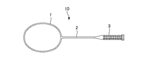
図1は、本発明に係るバドミントンラケットの正面図である。図1に示すように、バドミントンラケット10は、外観上は環状に形成されたフレーム1と、フレーム1に一方の端部が接合されたシャフト2と、シャフト2の他方の端部側に設けられたグリップ3とから構成されている。
FIG. 1 is a front view of a badminton racket according to the present invention. As shown in FIG. 1, the
図2は、フレームとシャフトとの接合部を示す断面図である。図2に示すように、フレーム1とシャフト2との接合部には、フレーム1の内部とシャフト2の内部とに渡って、ジョイント4が収容され、外側からフレームとシャフトとの境界部分を覆う補強部7にて補強されている。
FIG. 2 is a cross-sectional view showing the joint between the frame and the shaft. As shown in FIG. 2, a
フレーム1は、カーボン繊維を主体としたFRP製の中空管状体であり内部には発泡樹脂5を有している。また、シャフト2もカーボン繊維を主体としたFRP製の中空管状体であるが、内部は中空である。ジョイント4は例えばアルミニウム合金のような金属製の部材である。
The frame 1 is an FRP hollow tubular body mainly composed of carbon fibers, and has a
ジョイント4は、環状のフレーム1内に収容され僅かに湾曲したフレーム内被収容部4aと、フレーム内被収容部4aの長手方向におけるほぼ中央から、フレーム内被収容部4aとほぼ垂直に設けられたシャフト内被収容部4bとから構成されて、ほぼT字状をなしている。フレーム内被収容部4aの断面形状はフレーム1の断面形状と同じくバドミントンラケット10の打面の表裏面方向に長く扁平した楕円形状であり、シャフト内被収容部4bの断面形状はシャフト2の断面形状と同じ円形である。
The
フレーム内被収容部4aの外径は、フレーム1の内径より小さく形成されており、シャフト内被収容部4bの外径は、シャフト2の内径より小さく形成されている。
The outer diameter of the in-frame housing portion 4 a is smaller than the inner diameter of the frame 1, and the outer diameter of the inner
そして、フレーム1の内部とフレーム内被収容部4aとの間には、発泡樹脂6が介装され、フレーム1の内周面とフレーム内被収容部4aの外周面との間は、発泡樹脂6にて埋め尽くされている。 A foamed resin 6 is interposed between the inside of the frame 1 and the in-frame housing portion 4a, and a foamed resin is provided between the inner peripheral surface of the frame 1 and the outer peripheral surface of the in-frame housing portion 4a. It is filled with six.
この発泡樹脂6は、例えば、主剤であるエポキシ樹脂中間体と硬化剤である変形樹脂族ポリアミンとからなるエポキシ樹脂系弾性接着剤と、発泡剤であるニトリル系熱膨張性マイクロカプセルとが混合された発泡性樹脂が発泡した状態の樹脂であり、発泡性樹脂にはニトリル系熱膨張性マイクロカプセルは約10〜15%混合されている。 The foamed resin 6 includes, for example, an epoxy resin elastic adhesive composed of an epoxy resin intermediate as a main agent and a deformed resin group polyamine as a curing agent, and a nitrile thermal expansion microcapsule as a foaming agent. The foamable resin is in a foamed state, and about 10 to 15% of nitrile-based thermally expandable microcapsules are mixed in the foamable resin.
本実施形態のバドミントンラケット10によれば、フレーム1とシャフト2とに渡って内部に収容されたジョイント4とフレーム1との間に発泡樹脂6が介装されているので、フレーム1とジョイント4との間に空隙が生じにくく、面安定性が高いバドミントンラケット10を実現することが可能である。特にフレーム1とジョイント4との間に改装されている樹脂は発泡樹脂なので、未発泡の発泡性樹脂の状態でフレーム1とジョイント4との間に介装した後に発泡させることにより、発泡樹脂6をフレーム1とジョイント4との間の空隙に十分行き渡らせることが可能である。このため、衝撃やねじれにより強く、面安定性が高いバドミントンラケット10を実現し、打ったシャトルの方向性及びスピードを高めることが可能である。
According to the
図3は、バドミントンラケットの製造方法を示す図である。
図3に示すように、まず、複数の熱可塑性の樹脂シートとしてのカーボンプリプレグを同心状に積層して加熱し、バドミントンラケット10のシャフト2となる中空管状体を予め製造しておく(シャフト製造工程:S031)。
FIG. 3 is a diagram illustrating a method for manufacturing a badminton racket.
As shown in FIG. 3, first, a carbon tubular prepreg as a plurality of thermoplastic resin sheets is concentrically laminated and heated to preliminarily manufacture a hollow tubular body that becomes the
また、アルミニウム合金製のT字型のジョイント4には、フレーム内被収容部4aの外周に加熱されて発泡する発泡性樹脂6aを備えておく(発泡性樹脂具備工程:S021)。加熱されて発泡する発泡性樹脂6aは、ジョイント4のフレーム内被収容部4aを液体状の熱発泡性樹脂に浸した後乾燥させることによりコーティングしても良いし、予め、厚さ約0.3mmのシート状に形成した熱発泡性樹脂をフレーム内被収容部4aのシャフト内被収容部4bと繋がった部位を除いて巻き付けても良い。
The T-
次に、熱可塑性の樹脂シートとしてのカーボンプリプレグを複数積層し、その内側に加熱されて発泡する発泡性樹脂5aを配置して円筒状に巻いた樹脂シート筒を形成する(樹脂シート筒形成工程:S011)。このとき、発泡性樹脂5aが発泡した際に、樹脂シート筒の端から発泡樹脂5が突出しないように、カーボンプリプレグの内側に配置する発泡性樹脂5aは、樹脂シート筒の端より十分内側にて止めておく。
Next, a plurality of carbon prepregs as a thermoplastic resin sheet are stacked, and a
そして、樹脂シート筒を環状に屈曲させて突き合わせた両端部と、既に製造しておいたシャフト2との内部に渡って、発泡性樹脂6aを備えたジョイント4を装着して金型に設置した後に、加熱してフレーム1とシャフト2とを接合する(接合工程:S012)。このとき、環状に屈曲された樹脂シート筒の突き合わされる両端部における発泡性樹脂5aが配置されていない部位に発泡性樹脂6aを備えたジョイント4のフレーム内被収容部4aを装着し、シャフト2内にシャフト内被収容部4bを挿入させるとともに、シャフト2の先端をフレーム内被収容部4aに突き当てる。また、フレーム1とシャフト2との内部にジョイント4が装着された状態で金型に設置する前に、フレーム1とシャフト2と接合部に帯状のカーボンプリプレグを、樹脂シート筒の両端部に架け渡すように巻き付けておく。帯状のカーボンプリプレグが巻き付けられた部位は、フレーム1とシャフト2との接合部における補強部7となる。
Then, the
接合工程(S012)では、フレーム1を形成する樹脂シート筒の積層されたカーボンプリプレグシートが加熱されて塑性変形するが、その際、内部に配置されている発泡性樹脂5a、6aが膨張して樹脂シート筒の積層されたカーボンプリプレグシートを外方に押し広げ、カーボンプリプレグシートの外周面を金型に押圧する。このため、塑性変形した樹脂シート筒は、金型に沿わされて表面に凹凸のない滑らかな形状に形成される。また、樹脂シート筒の突き合わせた両端部、すなわち、フレーム1とシャフト2との接合部もジョイント4のフレーム内被収容部4aに備えられている発泡性樹脂6aが膨張して樹脂シート筒の端部のカーボンプリプレグシートを外方に押し広げて外周面を金型に押圧する。このため、フレーム1とシャフト2との接合部もフレーム1の他の部位と同様に表面に凹凸のない滑らかな形状に形成される。さらに、フレーム1とシャフト2との接合部にあっては、ジョイント4のフレーム内被収容部4aに備えられている発泡性樹脂6aが発泡して、フレーム1の内面とジョイント4との間隙を埋めるとともに硬化してシャフト2とともに一体となる。
In the joining step (S012), the laminated carbon prepreg sheets of the resin sheet cylinders forming the frame 1 are heated and plastically deformed. At that time, the
その後、フレーム1にストリングを張るための孔を形成して塗装し、グリップ3を取り付けてバドミントンラケット10が完成される(グリップ等取付工程:S013)。 Thereafter, holes for stringing are formed in the frame 1 and painted, and the grip 3 is attached to complete the badminton racket 10 (grip attachment step: S013).
本実施形態のバドミントンラケット10の製造方法によれば、樹脂シート筒が内部に備える発泡性樹脂5a及びジョイント4の外周に備えられてフレーム1内に収容される発泡性樹脂6aはいずれも熱により発泡するので、樹脂シート筒を環状に屈曲させて突き合わせた両端部と、シャフト2との内部にジョイント4を装着して金型に設置して加熱することにより、シャフト2との接合部も含めたフレーム1内で発泡性樹脂5a、6aを発泡させフレーム1内に充満させることが可能である。このとき、フレーム1を形成する樹脂シート筒の外周部は熱可塑性の樹脂シートにて形成されているので、金型を加熱することにより樹脂シート筒の外周部は塑性変形する。このため、樹脂シート筒の内部及びジョイント4の外周に備えられた発泡性樹脂5a、6aが発泡することにより樹脂シート筒が金型に沿うように押し広げられ、フレーム1を所望の形状に形成することが可能である。特に、フレーム1とシャフト2との接合部においても発泡性樹脂6aが発泡するので、フレーム1全体が金型に沿った所望の形状に形成されるとともに、フレーム1とジョイント4との間に空隙が生じることなくフレーム1とシャフト2とを接合することが可能である。このため、樹脂シート筒、シャフト2、及び、外周に発泡性樹脂6aを備えたジョイント4を金型に設置して加熱するだけで、より面安定性の高いバドミントンラケット10を容易に製造することが可能である。
According to the manufacturing method of the
さらに、フレーム1とジョイント4との間に介装されている発泡樹脂6は、加熱されて発泡する発泡剤を有しているので、加熱されて発泡した発泡剤により樹脂をフレーム1とジョイント4との間に空隙なく容易に行き渡らせることが可能である。このため、ジョイント4とフレーム1との間にて未発泡状態の発泡性樹脂6aを配置したうえで加熱することにより、発泡剤を発泡させてジョイント4とフレーム1との間の空隙を容易に埋めることが可能である。このため、製造性に優れたバドミントンラケット10を実現することが可能である。
Further, since the foamed resin 6 interposed between the frame 1 and the joint 4 has a foaming agent that foams when heated, the resin is removed from the frame 1 and the joint 4 by the foaming agent heated and foamed. It is possible to spread easily without any gaps between them. For this reason, by placing an unfoamed
また、加熱することにより発泡剤が膨張するとともに硬化剤により発泡性樹脂6a内の樹脂が硬化するので、フレーム1とジョイント4との間に発泡性樹脂6aを隙間なく行き渡らせて硬化させることが可能である。このため、フレーム1とジョイント4と硬化した発泡樹脂6とが一体となってより面安定性の高いバドミントンラケット10を供給することが可能である。
Moreover, since the foaming agent expands by heating and the resin in the
上記実施形態においては、ジョイント4を金属製としたが、樹脂等にて構成しても構わない。樹脂製のジョイントとしては、例えば、ナイロンなどの熱可塑性の樹脂が適用可能である。このように、ジョイントを樹脂にて構成すると、金属製のジョイントを用いた場合より軽量化を図ることが可能である。さらに、熱可塑性の樹脂にガラス繊維を混合した樹脂であればより好適である。熱可塑性の樹脂にガラス繊維を混合した樹脂は、軽量化を図るとともに強度を高めることも可能である。 In the above embodiment, the joint 4 is made of metal, but may be made of resin or the like. As the resin joint, for example, a thermoplastic resin such as nylon is applicable. Thus, if the joint is made of resin, it is possible to reduce the weight as compared with the case where a metal joint is used. Furthermore, it is more suitable if it is resin which mixed glass fiber with thermoplastic resin. A resin obtained by mixing glass fibers with a thermoplastic resin can reduce the weight and increase the strength.
また、上記実施形態においては、発泡性樹脂の一例として、主剤であるエポキシ樹脂中間体と硬化剤である変形樹脂族ポリアミンとからなるエポキシ樹脂系弾性接着剤と、発泡剤であるニトリル系熱膨張性マイクロカプセルとが混合された樹脂としたが、これに限るものではない。 Moreover, in the said embodiment, as an example of a foamable resin, the epoxy resin-type elastic adhesive which consists of the epoxy resin intermediate body which is the main ingredient, and the deformation resin group polyamine which is a hardening | curing agent, and the nitrile-type thermal expansion which is a foaming agent However, the present invention is not limited to this.
上記実施形態においては、バドミントンラケット10をストリングが張られていない状態として説明したが、ストリングが張られたバドミントンラケット10も含まれる。
In the above embodiment, the
尚、上記実施形態は、本発明の理解を容易にするためのものであり、本発明を限定して解釈するためのものではない。本発明は、その趣旨を逸脱することなく、変更、改良され得ると共に、本発明にはその等価物が含まれることはいうまでもない。 In addition, the said embodiment is for making an understanding of this invention easy, and is not for limiting and interpreting this invention. The present invention can be changed and improved without departing from the gist thereof, and it is needless to say that the present invention includes equivalents thereof.
1 フレーム、2 シャフト、3 グリップ、4 ジョイント、
4a フレーム内被収容部、4b シャフト内被収容部、5 発泡樹脂、
5a 発泡性樹脂、6 発泡樹脂、6a 発泡性樹脂、7 補強部、
10 バドミントンラケット
1 frame, 2 shafts, 3 grips, 4 joints,
4a Frame receiving portion, 4b Shaft receiving portion, 5 Foamed resin,
5a foamable resin, 6 foamed resin, 6a foamable resin, 7 reinforcing part,
10 Badminton rackets
Claims (3)
前記樹脂シート筒にて形成されるフレームの内部とシャフトの内部とに渡って収容されるジョイントの、前記フレームの内部に収容される部位の外周に、加熱されて発泡する発泡性樹脂を備える発泡性樹脂具備工程と、
前記樹脂シート筒を環状に屈曲させて突き合わせた両端部と、前記シャフトとの内部に前記発泡性樹脂を備えた前記ジョイントを装着して金型に設置した後に、前記フレームと前記シャフトとを接合する接合工程と、
を有し、
前記接合工程において、加熱することにより、
前記樹脂シート筒に備えられた前記発泡性樹脂が膨張して前記樹脂シートを前記金型に押圧すること、及び、
前記ジョイントに備えられた発泡性樹脂により前記両端部を前記金型に沿うように押し広げることが行われる、
ことを特徴とするバドミントンラケットの製造方法。 Inside the resin sheet, a resin sheet tube forming step of forming a resin sheet tube which the expandable resin placed wound in a cylindrical shape expands when heated,
Foam with a foamable resin that is heated and foamed on the outer periphery of a portion of the joint that is accommodated across the interior of the frame formed by the resin sheet cylinder and the interior of the shaft. A process for providing a functional resin;
After attaching the joint provided with the foamable resin inside the shaft and both ends of the resin sheet cylinder bent and butted together , the frame and the shaft are joined together A joining process to perform,
Have
In the joining step, by heating,
The foamable resin provided in the resin sheet cylinder expands and presses the resin sheet against the mold; and
The foaming resin provided in the joint is expanded to push the both end portions along the mold,
A method for producing a badminton racket.
Priority Applications (7)
| Application Number | Priority Date | Filing Date | Title |
|---|---|---|---|
| JP2007201172A JP5281767B2 (en) | 2007-08-01 | 2007-08-01 | Badminton racket manufacturing method |
| US12/671,449 US8211266B2 (en) | 2007-08-01 | 2008-07-29 | Badminton racket and manufacturing method of badminton racket |
| CN2008801104763A CN101808699B (en) | 2007-08-01 | 2008-07-29 | Badminton racket and manufacturing method of badminton racket |
| DK08791805.8T DK2177247T3 (en) | 2007-08-01 | 2008-07-29 | Badminton rackets and methods for making badminton rackets |
| CN201110405951.3A CN102366667B (en) | 2007-08-01 | 2008-07-29 | Badminton racket and manufacturing method of badminton racket |
| PCT/JP2008/063570 WO2009017112A1 (en) | 2007-08-01 | 2008-07-29 | Badminton racket and manufacturing method of badminton racket |
| EP08791805.8A EP2177247B1 (en) | 2007-08-01 | 2008-07-29 | Badminton racket and manufacturing method of badminton racket |
Applications Claiming Priority (1)
| Application Number | Priority Date | Filing Date | Title |
|---|---|---|---|
| JP2007201172A JP5281767B2 (en) | 2007-08-01 | 2007-08-01 | Badminton racket manufacturing method |
Publications (2)
| Publication Number | Publication Date |
|---|---|
| JP2009034333A JP2009034333A (en) | 2009-02-19 |
| JP5281767B2 true JP5281767B2 (en) | 2013-09-04 |
Family
ID=40304342
Family Applications (1)
| Application Number | Title | Priority Date | Filing Date |
|---|---|---|---|
| JP2007201172A Active JP5281767B2 (en) | 2007-08-01 | 2007-08-01 | Badminton racket manufacturing method |
Country Status (6)
| Country | Link |
|---|---|
| US (1) | US8211266B2 (en) |
| EP (1) | EP2177247B1 (en) |
| JP (1) | JP5281767B2 (en) |
| CN (2) | CN101808699B (en) |
| DK (1) | DK2177247T3 (en) |
| WO (1) | WO2009017112A1 (en) |
Families Citing this family (9)
| Publication number | Priority date | Publication date | Assignee | Title |
|---|---|---|---|---|
| US7727094B2 (en) * | 2008-02-22 | 2010-06-01 | Pick-A-Paddle, Inc. | Institutional badminton racket |
| TW201043294A (en) * | 2009-06-12 | 2010-12-16 | Chin Chia Shun Entpr Co Ltd | Expansion-molding method of badminton racket |
| CN102612427B (en) * | 2009-06-18 | 2016-08-03 | Xene公司 | A kind of fibrous composite and production technology |
| CN101590314A (en) * | 2009-06-18 | 2009-12-02 | 徐建昇 | The preparation method of fibrous racket frame |
| CN102698415A (en) * | 2012-06-29 | 2012-10-03 | 黄展刚 | Repairing method of carbon battledore |
| CN103055476A (en) * | 2012-12-28 | 2013-04-24 | 徐建昇 | Manufacture method of racket frame |
| JP6241934B2 (en) * | 2014-02-12 | 2017-12-06 | ダンロップスポーツ株式会社 | racket |
| CN105538579B (en) * | 2016-02-25 | 2017-09-26 | 江苏祺洋航碳纤科技有限公司 | Automatic mould opening machine of the carbon badminton racket without air pressure forming technology automatic assembly line |
| CN112704861B (en) * | 2020-12-07 | 2022-04-19 | 李宁(中国)体育用品有限公司 | Manufacturing method of badminton racket and badminton racket |
Family Cites Families (12)
| Publication number | Priority date | Publication date | Assignee | Title |
|---|---|---|---|---|
| US4360202A (en) * | 1978-09-08 | 1982-11-23 | Lo Kun Nan | CFRP or FRP made badminton racket frame |
| JPS6038141B2 (en) * | 1980-09-27 | 1985-08-30 | ヨネツクススポ−ツ株式会社 | badminton racket frame |
| JPS6099965U (en) * | 1983-12-16 | 1985-07-08 | ヨネックス株式会社 | badminton racket frame |
| JPS6114064U (en) * | 1984-06-28 | 1986-01-27 | ヨネツクス株式会社 | badminton racket frame |
| CN1062093A (en) | 1991-07-29 | 1992-06-24 | 白清栋 | Making method for seamless triangle portion of aluminium alloy tennis racket |
| EP0561040A1 (en) * | 1992-03-18 | 1993-09-22 | Ching-Dong Pai | Alloy racket frame |
| JP2762006B2 (en) * | 1992-11-09 | 1998-06-04 | 美津濃株式会社 | Method of forming racket frame for badminton |
| CN2164869Y (en) * | 1993-07-22 | 1994-05-18 | 尤景三 | Improved badminton racket |
| JPH08299513A (en) * | 1995-05-02 | 1996-11-19 | Fujii Kinzoku Kako Kk | Metallic bat |
| DE60336299D1 (en) * | 2002-01-22 | 2011-04-21 | Dow Global Technologies Inc | REINFORCED COMPOSITE COMPONENT AND METHOD FOR THE PRODUCTION THEREOF |
| JP2004065862A (en) * | 2002-08-09 | 2004-03-04 | Yonex Co Ltd | Badminton racket |
| US7211010B2 (en) * | 2005-09-03 | 2007-05-01 | Wilson Sporting Goods Co. | Reinforcing member for a badminton racquet |
-
2007
- 2007-08-01 JP JP2007201172A patent/JP5281767B2/en active Active
-
2008
- 2008-07-29 US US12/671,449 patent/US8211266B2/en active Active
- 2008-07-29 EP EP08791805.8A patent/EP2177247B1/en active Active
- 2008-07-29 DK DK08791805.8T patent/DK2177247T3/en active
- 2008-07-29 CN CN2008801104763A patent/CN101808699B/en not_active Expired - Fee Related
- 2008-07-29 WO PCT/JP2008/063570 patent/WO2009017112A1/en active Application Filing
- 2008-07-29 CN CN201110405951.3A patent/CN102366667B/en active Active
Also Published As
| Publication number | Publication date |
|---|---|
| DK2177247T3 (en) | 2018-06-18 |
| US8211266B2 (en) | 2012-07-03 |
| EP2177247B1 (en) | 2018-03-07 |
| EP2177247A4 (en) | 2012-11-07 |
| US20100212805A1 (en) | 2010-08-26 |
| CN102366667B (en) | 2014-05-14 |
| CN101808699A (en) | 2010-08-18 |
| EP2177247A1 (en) | 2010-04-21 |
| CN102366667A (en) | 2012-03-07 |
| JP2009034333A (en) | 2009-02-19 |
| WO2009017112A1 (en) | 2009-02-05 |
| CN101808699B (en) | 2012-09-05 |
Similar Documents
| Publication | Publication Date | Title |
|---|---|---|
| JP5281767B2 (en) | Badminton racket manufacturing method | |
| US5364095A (en) | Tubular metal ball bat internally reinforced with fiber composite | |
| US6251034B1 (en) | Ball bat | |
| US4070021A (en) | Composite high strength to weight structure having shell and sleeved core | |
| JP5855861B2 (en) | Ball bat including a barrel portion having separate proximal and distal members | |
| JP4897627B2 (en) | Composite bat with a single hollow primary tube | |
| EP1859838A1 (en) | Golf shaft having a multiple tube structure | |
| JP5948082B2 (en) | tennis racket | |
| JP5264454B2 (en) | Badminton racket and method for producing badminton racket | |
| JP4054342B2 (en) | Manufacturing method of FRP lined metal pipe | |
| JP7074549B2 (en) | Badminton racket and badminton racket manufacturing method | |
| US7883434B2 (en) | Composite bat having a multiple tube structure | |
| WO2001047611A1 (en) | Method for localizing weight in a golf club shaft | |
| GB2440509A (en) | Method of forming a badminton racquet having a T shaped joint | |
| JP2762006B2 (en) | Method of forming racket frame for badminton | |
| JP2835201B2 (en) | Baseball bat | |
| JPH10309334A (en) | Golf shaft and its production | |
| KR100257784B1 (en) | Tubular metal ball bat internally reinforced with fiber composite | |
| JP4498020B2 (en) | bat | |
| JPH10314354A (en) | Manufacture of metal tube for bicycle | |
| JPS6256122A (en) | Manufacture of fiber-reinforced synthetic resin tube | |
| JPH02291879A (en) | Manufacture of golf club shaft and golf club | |
| JPH05177014A (en) | Racket frame for badminton and its manufacture | |
| JP2017519601A (en) | Badminton racket and method for producing badminton racket | |
| JPH07194740A (en) | Tennis racket and production of this tennis racket |
Legal Events
| Date | Code | Title | Description |
|---|---|---|---|
| A621 | Written request for application examination |
Free format text: JAPANESE INTERMEDIATE CODE: A621 Effective date: 20100720 |
|
| A131 | Notification of reasons for refusal |
Free format text: JAPANESE INTERMEDIATE CODE: A131 Effective date: 20121218 |
|
| A521 | Request for written amendment filed |
Free format text: JAPANESE INTERMEDIATE CODE: A523 Effective date: 20130214 |
|
| TRDD | Decision of grant or rejection written | ||
| A01 | Written decision to grant a patent or to grant a registration (utility model) |
Free format text: JAPANESE INTERMEDIATE CODE: A01 Effective date: 20130430 |
|
| A61 | First payment of annual fees (during grant procedure) |
Free format text: JAPANESE INTERMEDIATE CODE: A61 Effective date: 20130527 |
|
| R150 | Certificate of patent or registration of utility model |
Free format text: JAPANESE INTERMEDIATE CODE: R150 Ref document number: 5281767 Country of ref document: JP Free format text: JAPANESE INTERMEDIATE CODE: R150 |
|
| R250 | Receipt of annual fees |
Free format text: JAPANESE INTERMEDIATE CODE: R250 |
|
| R250 | Receipt of annual fees |
Free format text: JAPANESE INTERMEDIATE CODE: R250 |
|
| R250 | Receipt of annual fees |
Free format text: JAPANESE INTERMEDIATE CODE: R250 |
|
| R250 | Receipt of annual fees |
Free format text: JAPANESE INTERMEDIATE CODE: R250 |
|
| R250 | Receipt of annual fees |
Free format text: JAPANESE INTERMEDIATE CODE: R250 |
|
| R250 | Receipt of annual fees |
Free format text: JAPANESE INTERMEDIATE CODE: R250 |
|
| R250 | Receipt of annual fees |
Free format text: JAPANESE INTERMEDIATE CODE: R250 |