EP2177196A1 - Vibration exerciser - Google Patents
Vibration exerciser Download PDFInfo
- Publication number
- EP2177196A1 EP2177196A1 EP08253355A EP08253355A EP2177196A1 EP 2177196 A1 EP2177196 A1 EP 2177196A1 EP 08253355 A EP08253355 A EP 08253355A EP 08253355 A EP08253355 A EP 08253355A EP 2177196 A1 EP2177196 A1 EP 2177196A1
- Authority
- EP
- European Patent Office
- Prior art keywords
- vibration
- platform
- base
- resilient
- exerciser
- Prior art date
- Legal status (The legal status is an assumption and is not a legal conclusion. Google has not performed a legal analysis and makes no representation as to the accuracy of the status listed.)
- Withdrawn
Links
Images


Classifications
-
- A—HUMAN NECESSITIES
- A61—MEDICAL OR VETERINARY SCIENCE; HYGIENE
- A61H—PHYSICAL THERAPY APPARATUS, e.g. DEVICES FOR LOCATING OR STIMULATING REFLEX POINTS IN THE BODY; ARTIFICIAL RESPIRATION; MASSAGE; BATHING DEVICES FOR SPECIAL THERAPEUTIC OR HYGIENIC PURPOSES OR SPECIFIC PARTS OF THE BODY
- A61H23/00—Percussion or vibration massage, e.g. using supersonic vibration; Suction-vibration massage; Massage with moving diaphragms
- A61H23/02—Percussion or vibration massage, e.g. using supersonic vibration; Suction-vibration massage; Massage with moving diaphragms with electric or magnetic drive
- A61H23/0254—Percussion or vibration massage, e.g. using supersonic vibration; Suction-vibration massage; Massage with moving diaphragms with electric or magnetic drive with rotary motor
- A61H23/0263—Percussion or vibration massage, e.g. using supersonic vibration; Suction-vibration massage; Massage with moving diaphragms with electric or magnetic drive with rotary motor using rotating unbalanced masses
-
- A—HUMAN NECESSITIES
- A61—MEDICAL OR VETERINARY SCIENCE; HYGIENE
- A61H—PHYSICAL THERAPY APPARATUS, e.g. DEVICES FOR LOCATING OR STIMULATING REFLEX POINTS IN THE BODY; ARTIFICIAL RESPIRATION; MASSAGE; BATHING DEVICES FOR SPECIAL THERAPEUTIC OR HYGIENIC PURPOSES OR SPECIFIC PARTS OF THE BODY
- A61H1/00—Apparatus for passive exercising; Vibrating apparatus ; Chiropractic devices, e.g. body impacting devices, external devices for briefly extending or aligning unbroken bones
- A61H1/005—Moveable platform, e.g. vibrating or oscillating platform for standing, sitting, laying, leaning
-
- A—HUMAN NECESSITIES
- A63—SPORTS; GAMES; AMUSEMENTS
- A63B—APPARATUS FOR PHYSICAL TRAINING, GYMNASTICS, SWIMMING, CLIMBING, OR FENCING; BALL GAMES; TRAINING EQUIPMENT
- A63B2208/00—Characteristics or parameters related to the user or player
- A63B2208/02—Characteristics or parameters related to the user or player posture
- A63B2208/0204—Standing on the feet
Definitions
- the present invention relates to an exerciser, and more particularly to a vibration exerciser.
- a vibration exerciser has a vibrated platform to provide a vibrating effect to a user who steps, sits or lies or abuts on the platform for training or exercising muscles of the user.
- a conventional vibration exerciser comprises a base (70), multiple supporting members (71), a platform (72) and a vibration generator (73).
- the supporting members (71) are securely attached to the base(70) along a direction vertical to the base (70) and each has a spring.
- the platform (72) is connected to and supported by the tops of the supporting members (71).
- the vibration generator (73) is securely attached to the bottom of the platform (72) to make the platform (72) vibration.
- another conventional vibration exerciser comprises a base (80), multiple lower resilient elements (81), a supporting board (82), multiple upper resilient elements (83), a platform (84) and a vibration generator (85).
- the lower resilient elements (81) are mounted securely on the base (80).
- the supporting board (82) is attached securely to and supported by the lower resilient elements (81).
- the upper resilient elements (83) are attached securely to the top of the supporting board (82).
- the platform (84) is mounted on and supported by the upper resilient elements (83).
- the vibration generator (85) is securely attached to the bottom of the platform (84) to make the platform (84) vibration.
- the supporting members (71) and the resilient elements (81,83) of the conventional vibration exercisers support the platform (72,84) along a direction substantially vertical to the corresponding base (70,80), so the vibration action of the platform (72,84) will impact the user directly. Consequently, less vibration force cannot provide enough training and exercising effect, but a user is easily injured by a large longitudinal vibration force.
- the present invention tends to provide a vibration exerciser to mitigate or obviate the aforementioned problems.
- the main objective of the invention is to provide a vibration exerciser that can provide gentle and adjustable vibration force to a user.
- the vibration exerciser comprises a base, a platform, a vibration generator and a resilient assembly.
- the platform is connected operationally to the base and has a bottom.
- the vibration generator is attached to the bottom of the platform to make the platform vibration.
- the resilient assembly is mounted around the base and is connected to the platform along a lateral direction.
- a vibration exerciser in accordance with the present invention comprises a base (10), a platform (20), a vibration generator (30) and a resilient assembly (40).
- the base (10) comprises a rectangular bottom panel (11) and two supporting brackets (12).
- the supporting brackets (12) are securely attached to the bottom panel (11) and each has multiple supporting posts (13) and a top panel (14).
- the supporting posts (13) are securely attached to the top of the bottom panel (11), and the top panel (14) is securely attached to the tops of the supporting posts (13).
- the platform (20) is connected operationally to the base (10) and has a side wall (21) formed around and extending downward from the periphery of the platform (20) to define a chamber in the platform (20).
- the side wall (21) has multiple connecting elements (22) defined on the side wall (21). In a preferred embodiment, each connecting element (22) is a hole defined in the side wall (21).
- the vibration generator (30) is attached to the bottom of the platform (20) to make the platform (20) vibration.
- the vibration generator (30) may be a mechanical vibration generator having a motor with a cam or an eccentric block or levers, sound waves type vibration generator or any possible conventional vibration generating device.
- the resilient assembly (40) is mounted around the base (10) and is connected to the platform (20) along a lateral direction that is substantially parallel with the bottom panel (11) of the base (10).
- the resilient assembly (40) comprises multiple springs (41).
- Each spring (41) has two ends connected respectively to a side of the base (10) and a side of the platform (20).
- one end of each spring (41) is connected to a hole defined in the top panel (14) of one of the supporting brackets (12).
- the other end of each spring (41) is connected to one of the connecting elements (22) on the side wall (21) of the platform (20).
- the resilient assembly (40) comprises an annular resilient sheet (41a) mounted around the base (10) and held inside the chamber in the platform (20).
- the resilient sheet (41a) is made of rubber material and has an inner edge and an outer edge.
- the inner edge of the resilient sheet (41 a) is securely attached to and mounted around the base (10) with multiple connecting members.
- the outer edge of the resilient sheet (41 a) is securely attached to the platform (20) with multiple connecting members.
- the connecting members may be bolts, nails, hooks, loops or the like.
- the resilient assembly (40) comprises multiple resilient bodies (41b) mounted around the base (10) at intervals and held inside the chamber in the platform (20).
- Each resilient body (41b) is made of rubber material and has an inner side and an outer side.
- the inner side of the resilient sheet (41b) is securely attached to a side of the top panel (14) of one of the supporting brackets (12) on the base (10) with multiple connecting members.
- the outer side of the resilient body (41b) is securely attached to a side of the side wall (21) on the platform (22) with multiple connecting members.
- the connecting members may be bolts, nails, hooks, loops or the like.
- a user can step, sit, lie or abut on the platform (22) and turns on the vibration generator (30) to make the platform (20) vibrating and shocking.
- the vibration of the platform (20) muscles of the user can be excited and provided with a training and exercising effect.
- the resilient assembly (40) arranged along a lateral direction part of the vibration force applied to the platform (20) will be transferred to a lateral component force to make the force applied to the user becoming gentle and comfortable. With the gentle vibration force due to the arrangement of the lateral resilient assembly (40), the user can be kept from being injured.
- the resilient assembly (40) when the resilient assembly (40) is implemented with the annular resilient sheet (41a) or multiple resilient bodies (41b), the inner surface of the side wall (21) on the platform (20) and the periphery of the top panel (14) of each supporting bracket (12) on the base are curved at corners to keep the resilient sheet (41a) or bodies (41b) from being damaged.
- the vibration exerciser may further comprise an auxiliary supporting device (50) as shown in Figs. 6 and 7 .
- the auxiliary supporting device (50) has at least one supporting member (51) connected to the base (10) and abutting with the resilient assembly (40).
- the auxiliary supporting device (50) has multiple supporting members (51).
- Each supporting member (51) has a convex abutting end (511) abutting with a bottom of the resilient sheet (41 a) or one of the resilient bodies (41b).
- Each supporting member (51) may have a positioning tab (512) formed on and extending longitudinally from a side of the supporting member (51).
- the auxiliary supporting device (50) may further comprise multiple adjusting elements (52) connected respectively to the supporting members (51) to adjust a position where the abutting end (511) of each supporting member (51) abuts with the resilient sheet (41a) or a corresponding resilient body (41b).
- Each adjusting element (52) is L-shaped and comprises a longitudinal tab (521) and a lateral tab (522).
- the longitudinal tab (521) is connected adjustably to the positioning tab (512) of a corresponding supporting member (51), and the lateral tab (522) is attached adjustably to the bottom panel (11) of the base (10).
- the positioning tab (512) has a through hole defined through the positioning tab (512).
- the longitudinal tab (521) has multiple through holes or an elongated slot defined through the longitudinal tab (521).
- a fastener extends through the through hole in the positioning tab (512) and one of the through holes or the slot in the longitudinal tab (521), such that the positioning tab (512) is connected adjustably to the longitudinal tab (521) with the fastener.
- the lateral tab (522) has multiple through holes or an elongated slot defined through the lateral tab (522).
- a fastener extends through one of the through holes or the slot in the lateral tab (522) and the base (10) to make the lateral tab (522) connected adjustably to the base (10).
- the longitudinal heights and lateral positions of the abutting ends (511) of the supporting members (51) abutting with the resilient sheet (41a) or the resilient bodies (41b) can be changed.
- the vibration force and the amplitude of vibration of the platform can be adjusted due to the following formula.
- the vibration exerciser With the adjustable vibration force and amplitude of vibration, the training and the exercising effects provided by the vibration exerciser can be improved and the vibration exerciser is versatile in use.
- the vibration exerciser in accordance with the present invention may further comprises a resilient supporting device (60) mounted on the top of the base (10) and connected to the bottom of the platform (20).
- the resilient supporting device (60) may comprises at least one spring (61) attached to the top panels (14) of the base (10) and connected to the bottom of the platform (20) to provide a longitudinal and auxiliary supporting effect to the platform (20).
Abstract
A vibration exerciser has a base (10), a platform (20), a vibration generator (30) and a resilient assembly (40). The platform (20) is connected operationally to the base (10) and has a bottom. The vibration generator (30) is attached to the bottom of the platform (20) to make the platform (20) vibration. The resilient assembly (40) is mounted around the base (10) and is connected to the platform (20) along a lateral direction. Accordingly, the vibration exerciser can provide a gentle vibration force to a user to keep the user from being injured.
Description
- The present invention relates to an exerciser, and more particularly to a vibration exerciser.
- A vibration exerciser has a vibrated platform to provide a vibrating effect to a user who steps, sits or lies or abuts on the platform for training or exercising muscles of the user.
- With reference to
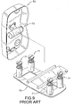
Figs. 9 and10 , a conventional vibration exerciser comprises a base (70), multiple supporting members (71), a platform (72) and a vibration generator (73). The supporting members (71) are securely attached to the base(70) along a direction vertical to the base (70) and each has a spring. The platform (72) is connected to and supported by the tops of the supporting members (71). The vibration generator (73) is securely attached to the bottom of the platform (72) to make the platform (72) vibration. - With reference to
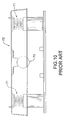
Fig. 11 , another conventional vibration exerciser comprises a base (80), multiple lower resilient elements (81), a supporting board (82), multiple upper resilient elements (83), a platform (84) and a vibration generator (85). The lower resilient elements (81) are mounted securely on the base (80). The supporting board (82) is attached securely to and supported by the lower resilient elements (81). The upper resilient elements (83) are attached securely to the top of the supporting board (82). The platform (84) is mounted on and supported by the upper resilient elements (83). The vibration generator (85) is securely attached to the bottom of the platform (84) to make the platform (84) vibration. - By researches, there are three indexes including frequency, amplitude and acceleration will influence the vibration effect provided to a user. However, the supporting members (71) and the resilient elements (81,83) of the conventional vibration exercisers support the platform (72,84) along a direction substantially vertical to the corresponding base (70,80), so the vibration action of the platform (72,84) will impact the user directly. Consequently, less vibration force cannot provide enough training and exercising effect, but a user is easily injured by a large longitudinal vibration force.
- To overcome the shortcomings, the present invention tends to provide a vibration exerciser to mitigate or obviate the aforementioned problems.
- The main objective of the invention is to provide a vibration exerciser that can provide gentle and adjustable vibration force to a user.
- The vibration exerciser comprises a base, a platform, a vibration generator and a resilient assembly. The platform is connected operationally to the base and has a bottom. The vibration generator is attached to the bottom of the platform to make the platform vibration. The resilient assembly is mounted around the base and is connected to the platform along a lateral direction.
- Other objects, advantages and novel features of the invention will become more apparent from the following detailed description when taken in conjunction with the accompanying drawings.
-
-
Fig. 1 is an exploded perspective view of a first embodiment of a vibration exerciser in accordance with the present invention; -
Fig. 2 is a top view in partial section of the vibration exerciser inFig. 1 ; -
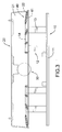
Fig. 3 is a side view of the vibration exerciser inFig. 1 ; -
Fig. 4 is a top view in partial section of a second embodiment of a vibration exerciser in accordance with the present invention; -
Fig. 5 is a top view in partial section of a third embodiment of a vibration exerciser in accordance with the present invention; -
Fig. 6 is a side view in partial section of the vibration exerciser inFig. 4 or5 ; -
Fig. 7 is an enlarged side view in partial section of the vibration exerciser inFig. 6 ; -
Fig. 8 is a side view of a fourth embodiment of a vibration exerciser in accordance with the present invention; -
Fig. 9 is an exploded perspective view of a conventional vibration exerciser in accordance with the prior art; -
Fig. 10 is a side view of the vibration exerciser inFig. 9 ; and -
Fig. 11 is a side view of another conventional vibration exerciser in accordance with the prior art. - With reference to
Figs. 1 to 5 , a vibration exerciser in accordance with the present invention comprises a base (10), a platform (20), a vibration generator (30) and a resilient assembly (40). The base (10) comprises a rectangular bottom panel (11) and two supporting brackets (12). The supporting brackets (12) are securely attached to the bottom panel (11) and each has multiple supporting posts (13) and a top panel (14). The supporting posts (13) are securely attached to the top of the bottom panel (11), and the top panel (14) is securely attached to the tops of the supporting posts (13). - The platform (20) is connected operationally to the base (10) and has a side wall (21) formed around and extending downward from the periphery of the platform (20) to define a chamber in the platform (20). The side wall (21) has multiple connecting elements (22) defined on the side wall (21). In a preferred embodiment, each connecting element (22) is a hole defined in the side wall (21).
- The vibration generator (30) is attached to the bottom of the platform (20) to make the platform (20) vibration. The vibration generator (30) may be a mechanical vibration generator having a motor with a cam or an eccentric block or levers, sound waves type vibration generator or any possible conventional vibration generating device.
- The resilient assembly (40) is mounted around the base (10) and is connected to the platform (20) along a lateral direction that is substantially parallel with the bottom panel (11) of the base (10).
- With reference to
Figs. 1 and3 , in a first embodiment, the resilient assembly (40) comprises multiple springs (41). Each spring (41) has two ends connected respectively to a side of the base (10) and a side of the platform (20). In the preferred embodiment, one end of each spring (41) is connected to a hole defined in the top panel (14) of one of the supporting brackets (12). The other end of each spring (41) is connected to one of the connecting elements (22) on the side wall (21) of the platform (20). - With reference to
Fig. 4 , in a second embodiment, the resilient assembly (40) comprises an annular resilient sheet (41a) mounted around the base (10) and held inside the chamber in the platform (20). The resilient sheet (41a) is made of rubber material and has an inner edge and an outer edge. The inner edge of the resilient sheet (41 a) is securely attached to and mounted around the base (10) with multiple connecting members. The outer edge of the resilient sheet (41 a) is securely attached to the platform (20) with multiple connecting members. The connecting members may be bolts, nails, hooks, loops or the like. - With reference to
Fig. 5 , in a third embodiment, the resilient assembly (40) comprises multiple resilient bodies (41b) mounted around the base (10) at intervals and held inside the chamber in the platform (20). Each resilient body (41b) is made of rubber material and has an inner side and an outer side. The inner side of the resilient sheet (41b) is securely attached to a side of the top panel (14) of one of the supporting brackets (12) on the base (10) with multiple connecting members. The outer side of the resilient body (41b) is securely attached to a side of the side wall (21) on the platform (22) with multiple connecting members. The connecting members may be bolts, nails, hooks, loops or the like. - In use of the vibration exerciser, a user can step, sit, lie or abut on the platform (22) and turns on the vibration generator (30) to make the platform (20) vibrating and shocking. With the vibration of the platform (20), muscles of the user can be excited and provided with a training and exercising effect. With the resilient assembly (40) arranged along a lateral direction, part of the vibration force applied to the platform (20) will be transferred to a lateral component force to make the force applied to the user becoming gentle and comfortable. With the gentle vibration force due to the arrangement of the lateral resilient assembly (40), the user can be kept from being injured.
- In addition, when the resilient assembly (40) is implemented with the annular resilient sheet (41a) or multiple resilient bodies (41b), the inner surface of the side wall (21) on the platform (20) and the periphery of the top panel (14) of each supporting bracket (12) on the base are curved at corners to keep the resilient sheet (41a) or bodies (41b) from being damaged.
- Additionally, when the resilient assembly (40) is implemented with the annular resilient sheet (41a) or multiple resilient bodies (41b), the vibration exerciser may further comprise an auxiliary supporting device (50) as shown in
Figs. 6 and7 . The auxiliary supporting device (50) has at least one supporting member (51) connected to the base (10) and abutting with the resilient assembly (40). In a preferable embodiment, the auxiliary supporting device (50) has multiple supporting members (51). Each supporting member (51) has a convex abutting end (511) abutting with a bottom of the resilient sheet (41 a) or one of the resilient bodies (41b). Each supporting member (51) may have a positioning tab (512) formed on and extending longitudinally from a side of the supporting member (51). - The auxiliary supporting device (50) may further comprise multiple adjusting elements (52) connected respectively to the supporting members (51) to adjust a position where the abutting end (511) of each supporting member (51) abuts with the resilient sheet (41a) or a corresponding resilient body (41b). Each adjusting element (52) is L-shaped and comprises a longitudinal tab (521) and a lateral tab (522). The longitudinal tab (521) is connected adjustably to the positioning tab (512) of a corresponding supporting member (51), and the lateral tab (522) is attached adjustably to the bottom panel (11) of the base (10). To adjustably connect the longitudinal tab (521) to the corresponding positioning tab (512), the positioning tab (512) has a through hole defined through the positioning tab (512). The longitudinal tab (521) has multiple through holes or an elongated slot defined through the longitudinal tab (521). A fastener extends through the through hole in the positioning tab (512) and one of the through holes or the slot in the longitudinal tab (521), such that the positioning tab (512) is connected adjustably to the longitudinal tab (521) with the fastener. To adjustably connect the lateral tab (522) to the base (10), the lateral tab (522) has multiple through holes or an elongated slot defined through the lateral tab (522). A fastener extends through one of the through holes or the slot in the lateral tab (522) and the base (10) to make the lateral tab (522) connected adjustably to the base (10).
- With the arrangement of the adjusting elements (52), the longitudinal heights and lateral positions of the abutting ends (511) of the supporting members (51) abutting with the resilient sheet (41a) or the resilient bodies (41b) can be changed. With the change of the abutting positions between the supporting members (51) and the resilient assembly (40), the vibration force and the amplitude of vibration of the platform can be adjusted due to the following formula.

and
Wherein, F is the vibration force that is a centrifugal force, m is the mass of the resilient sheet/body, r is radius of vibration of the resilient sheet/body, T is the cycle of vibration, v is the speed and ω is angular speed. - With the adjustable vibration force and amplitude of vibration, the training and the exercising effects provided by the vibration exerciser can be improved and the vibration exerciser is versatile in use.
- With reference to
Fig. 8 , the vibration exerciser in accordance with the present invention may further comprises a resilient supporting device (60) mounted on the top of the base (10) and connected to the bottom of the platform (20). The resilient supporting device (60) may comprises at least one spring (61) attached to the top panels (14) of the base (10) and connected to the bottom of the platform (20) to provide a longitudinal and auxiliary supporting effect to the platform (20).
Claims (11)
- A vibration exerciser comprising:a base (10);a platform (20) connected operationally to the base (10) and having a bottom; anda vibration generator (30) attached to the bottom of the platform (20) to make the platform (20) vibration, characterized in that the vibration exerciser further comprisesa resilient assembly (40) mounted around the base (10) and connected to the platform (20) along a lateral direction.
- The vibration exerciser as claimed in claim 1, wherein the resilient assembly (40) comprises multiple springs (41) each having two ends connected respectively to a side of the base (10) and a side of the platform (20).
- The vibration exerciser as claimed in claim 1, wherein the resilient assembly (40) comprises an annular resilient sheet (41a) havingan inner edge securely attached to and mounted around the base (10); andan outer edge securely attached to the platform (20).
- The vibration exerciser as claimed in claim 3 further comprising an auxiliary supporting device (50) having at least one supporting member (51) connected to the base (10) and abutting with the resilient sheet (41 a), wherein each one of the at least one supporting member (51) has a convex abutting end (511) abutting with a bottom of the resilient sheet (41a).
- The vibration exerciser as claimed in claim 4, wherein the auxiliary supporting device (50) further comprises at least one adjusting element (52) connected respectively to the at least one supporting member (51) to adjust a position where the abutting end (511) of each one of the at least one supporting member (51) abuts with the resilient sheet (41a).
- The vibration exerciser as claimed in claim 5, wherein each one of the at least one supporting member (51) has a positioning tab (512) formed on and extending longitudinally from a side of the supporting member (51); andeach one of the at least one adjusting element (52) is L-shaped and comprisesa longitudinal tab (521) connected adjustably to the positioning tab (512) of a corresponding one of the at least one supporting member (51); anda lateral tab (522) attached adjustably to the base (10).
- The vibration exerciser as claimed in claim 1, wherein the resilient assembly (40) comprises multiple resilient bodies (41b) each havingan inner side securely attached to a side of the base (10); andan outer side securely attached to a side of the platform (20).
- The vibration exerciser as claimed in claim 7 further comprising an auxiliary supporting device (50) having multiple supporting members (51) connected to the base (10) and abutting respectively with the resilient bodies (4 1 b), wherein each supporting member (51) has a convex abutting end (511) abutting with a bottom of one of the resilient bodies (4 1 b).
- The vibration exerciser as claimed in claim 8, wherein the auxiliary supporting device (50) further comprises multiple adjusting elements (52) connected respectively to the supporting members (51) to adjust a position where the abutting end (511) of each supporting member (51) abuts with a corresponding resilient body (41b).
- The vibration exerciser as claimed in claim 9, wherein each supporting member (51) has a positioning tab (512) formed on and extending longitudinally from a side of the supporting member (51); andeach adjusting element (52) is L-shaped and comprisesa longitudinal tab (521) connected adjustably to the positioning tab (512) of a corresponding one of the supporting members (51); anda lateral tab (522) attached adjustably to the base (10).
- The vibration exerciser as claimed in any one of claims 1 to 10 further comprising a resilient supporting device (60) mounted on a top of the base (10) and connected to the bottom of the platform (20).
Priority Applications (1)
| Application Number | Priority Date | Filing Date | Title |
|---|---|---|---|
| EP08253355A EP2177196A1 (en) | 2008-10-16 | 2008-10-16 | Vibration exerciser |
Applications Claiming Priority (1)
| Application Number | Priority Date | Filing Date | Title |
|---|---|---|---|
| EP08253355A EP2177196A1 (en) | 2008-10-16 | 2008-10-16 | Vibration exerciser |
Publications (1)
| Publication Number | Publication Date |
|---|---|
| EP2177196A1 true EP2177196A1 (en) | 2010-04-21 |
Family
ID=40128194
Family Applications (1)
| Application Number | Title | Priority Date | Filing Date |
|---|---|---|---|
| EP08253355A Withdrawn EP2177196A1 (en) | 2008-10-16 | 2008-10-16 | Vibration exerciser |
Country Status (1)
| Country | Link |
|---|---|
| EP (1) | EP2177196A1 (en) |
Cited By (4)
| Publication number | Priority date | Publication date | Assignee | Title |
|---|---|---|---|---|
| ES2393393A1 (en) * | 2010-06-18 | 2012-12-20 | Byomedic System, S.L.U. | Unstable vibratory platform with elastic resistance system for the application of mechanical vibration to the human body for physical conditioning. (Machine-translation by Google Translate, not legally binding) |
| ES2646754A1 (en) * | 2016-06-08 | 2017-12-15 | Gerard Moras Feliu | Vibratory platform with sliding surface for sliding exercises with mechanical vibration. (Machine-translation by Google Translate, not legally binding) |
| CN113301880A (en) * | 2019-02-22 | 2021-08-24 | 贾奎什生物医学公司 | Improved exercise apparatus |
| ES2941582A1 (en) * | 2021-11-22 | 2023-05-23 | Viequipment SCP | Vibrating platform with tilting movement of the vibrating plate for the application of mechanical vibration to the human body for physical conditioning (Machine-translation by Google Translate, not legally binding) |
Citations (5)
| Publication number | Priority date | Publication date | Assignee | Title |
|---|---|---|---|---|
| US5716331A (en) * | 1997-02-04 | 1998-02-10 | Chang; Li-Hsia | Massage device having a motor for vibrating and reciprocating a massage pad with protrusions |
| NL1020530C2 (en) * | 2002-05-03 | 2003-11-06 | Fitshape B V | Vibration device for creating muscle contractions, has plate for user to stand on provided with rubber suspension |
| WO2005067860A1 (en) * | 2004-01-13 | 2005-07-28 | Gerry Cook | Therapeutic vibration apparatus |
| US20060241528A1 (en) * | 2005-03-07 | 2006-10-26 | Talish Roger J | System and method for a low profile vibrating plate |
| WO2007113875A1 (en) * | 2006-04-04 | 2007-10-11 | Bios S.R.L. | Body treatment and anti-ageing apparatus |
-
2008
- 2008-10-16 EP EP08253355A patent/EP2177196A1/en not_active Withdrawn
Patent Citations (5)
| Publication number | Priority date | Publication date | Assignee | Title |
|---|---|---|---|---|
| US5716331A (en) * | 1997-02-04 | 1998-02-10 | Chang; Li-Hsia | Massage device having a motor for vibrating and reciprocating a massage pad with protrusions |
| NL1020530C2 (en) * | 2002-05-03 | 2003-11-06 | Fitshape B V | Vibration device for creating muscle contractions, has plate for user to stand on provided with rubber suspension |
| WO2005067860A1 (en) * | 2004-01-13 | 2005-07-28 | Gerry Cook | Therapeutic vibration apparatus |
| US20060241528A1 (en) * | 2005-03-07 | 2006-10-26 | Talish Roger J | System and method for a low profile vibrating plate |
| WO2007113875A1 (en) * | 2006-04-04 | 2007-10-11 | Bios S.R.L. | Body treatment and anti-ageing apparatus |
Cited By (4)
| Publication number | Priority date | Publication date | Assignee | Title |
|---|---|---|---|---|
| ES2393393A1 (en) * | 2010-06-18 | 2012-12-20 | Byomedic System, S.L.U. | Unstable vibratory platform with elastic resistance system for the application of mechanical vibration to the human body for physical conditioning. (Machine-translation by Google Translate, not legally binding) |
| ES2646754A1 (en) * | 2016-06-08 | 2017-12-15 | Gerard Moras Feliu | Vibratory platform with sliding surface for sliding exercises with mechanical vibration. (Machine-translation by Google Translate, not legally binding) |
| CN113301880A (en) * | 2019-02-22 | 2021-08-24 | 贾奎什生物医学公司 | Improved exercise apparatus |
| ES2941582A1 (en) * | 2021-11-22 | 2023-05-23 | Viequipment SCP | Vibrating platform with tilting movement of the vibrating plate for the application of mechanical vibration to the human body for physical conditioning (Machine-translation by Google Translate, not legally binding) |
Similar Documents
| Publication | Publication Date | Title |
|---|---|---|
| US8007422B2 (en) | Device for an exercise machine | |
| EP2177196A1 (en) | Vibration exerciser | |
| EP1427487B1 (en) | Training apparatus/chair | |
| EP1928393B1 (en) | Fitness machine having a vibration absorbing support | |
| US7438696B2 (en) | Physical therapy platform assembly | |
| US20070239088A1 (en) | Body vibration machine | |
| EP2123508B1 (en) | Seat | |
| US20100100016A1 (en) | Platform assembly for a vibration exerciser | |
| JP4519844B2 (en) | Fitness machine | |
| WO2010015047A2 (en) | A body vibrating device | |
| EP1844749B1 (en) | Body vibration machine | |
| EP2100580A1 (en) | Vibration-exercising machine | |
| CN104599661A (en) | Anti-vibration table | |
| WO2008063048A1 (en) | Training device, training assembly and training method | |
| EP2243458B1 (en) | Oscillation fitness platform | |
| JP2008264249A (en) | Training board and training apparatus with training board | |
| US20150231448A1 (en) | Exercise platform | |
| CN103888096B (en) | Piezoelectric vibrating assembly | |
| CN101711715A (en) | Vibration horse block of vibration trainer | |
| JP2009142341A (en) | Seat structure | |
| KR20090002994U (en) | top and bottom vibration exercise equipment | |
| JP3227883U (en) | Exercise equipment | |
| RU101356U1 (en) | MULTIFUNCTIONAL VIBRATION TRAINING DEVICE | |
| WO2010040244A1 (en) | A vibrating foot platform of an exercise vibrator | |
| WO2009048317A1 (en) | Oscillating training device, information support device, damping device and the use thereof |
Legal Events
| Date | Code | Title | Description |
|---|---|---|---|
| PUAI | Public reference made under article 153(3) epc to a published international application that has entered the european phase |
Free format text: ORIGINAL CODE: 0009012 |
|
| AK | Designated contracting states |
Kind code of ref document: A1 Designated state(s): AT BE BG CH CY CZ DE DK EE ES FI FR GB GR HR HU IE IS IT LI LT LU LV MC MT NL NO PL PT RO SE SI SK TR |
|
| AX | Request for extension of the european patent |
Extension state: AL BA MK RS |
|
| AKY | No designation fees paid | ||
| REG | Reference to a national code |
Ref country code: DE Ref legal event code: 8566 |
|
| STAA | Information on the status of an ep patent application or granted ep patent |
Free format text: STATUS: THE APPLICATION IS DEEMED TO BE WITHDRAWN |
|
| 18D | Application deemed to be withdrawn |
Effective date: 20101022 |