EP2176833B1 - Method and system for determining the position and orientation of a camera relative to a real object - Google Patents
Method and system for determining the position and orientation of a camera relative to a real object Download PDFInfo
- Publication number
- EP2176833B1 EP2176833B1 EP08773853.0A EP08773853A EP2176833B1 EP 2176833 B1 EP2176833 B1 EP 2176833B1 EP 08773853 A EP08773853 A EP 08773853A EP 2176833 B1 EP2176833 B1 EP 2176833B1
- Authority
- EP
- European Patent Office
- Prior art keywords
- real object
- camera
- data model
- sensor system
- virtual data
- Prior art date
- Legal status (The legal status is an assumption and is not a legal conclusion. Google has not performed a legal analysis and makes no representation as to the accuracy of the status listed.)
- Active
Links
- 238000000034 method Methods 0.000 title claims description 52
- 239000000523 sample Substances 0.000 claims description 37
- 230000008569 process Effects 0.000 claims description 15
- 238000004422 calculation algorithm Methods 0.000 claims description 13
- 238000005259 measurement Methods 0.000 claims description 13
- 238000013499 data model Methods 0.000 claims description 10
- 238000013461 design Methods 0.000 claims description 9
- 238000012545 processing Methods 0.000 claims description 7
- 238000004590 computer program Methods 0.000 claims description 3
- 230000000717 retained effect Effects 0.000 claims 1
- 230000009466 transformation Effects 0.000 description 41
- 230000003287 optical effect Effects 0.000 description 14
- 230000003190 augmentative effect Effects 0.000 description 10
- 230000008901 benefit Effects 0.000 description 5
- 238000000844 transformation Methods 0.000 description 5
- 238000004364 calculation method Methods 0.000 description 4
- 238000010276 construction Methods 0.000 description 4
- 238000012937 correction Methods 0.000 description 4
- 230000000007 visual effect Effects 0.000 description 4
- 230000008859 change Effects 0.000 description 3
- 230000001419 dependent effect Effects 0.000 description 3
- 238000012800 visualization Methods 0.000 description 3
- 230000005540 biological transmission Effects 0.000 description 2
- 238000005516 engineering process Methods 0.000 description 2
- 230000006870 function Effects 0.000 description 2
- 239000003550 marker Substances 0.000 description 2
- 238000005457 optimization Methods 0.000 description 2
- 238000012356 Product development Methods 0.000 description 1
- 230000000295 complement effect Effects 0.000 description 1
- 230000008878 coupling Effects 0.000 description 1
- 238000010168 coupling process Methods 0.000 description 1
- 238000005859 coupling reaction Methods 0.000 description 1
- 238000001514 detection method Methods 0.000 description 1
- 238000011161 development Methods 0.000 description 1
- 238000006073 displacement reaction Methods 0.000 description 1
- 230000000694 effects Effects 0.000 description 1
- 238000013401 experimental design Methods 0.000 description 1
- 239000011521 glass Substances 0.000 description 1
- 238000003780 insertion Methods 0.000 description 1
- 230000037431 insertion Effects 0.000 description 1
- 238000011835 investigation Methods 0.000 description 1
- 238000012423 maintenance Methods 0.000 description 1
- 238000004519 manufacturing process Methods 0.000 description 1
- 239000000463 material Substances 0.000 description 1
- 238000010297 mechanical methods and process Methods 0.000 description 1
- 238000012986 modification Methods 0.000 description 1
- 230000004048 modification Effects 0.000 description 1
- 230000002441 reversible effect Effects 0.000 description 1
- 238000012360 testing method Methods 0.000 description 1
Images


Classifications
-
- G—PHYSICS
- G06—COMPUTING; CALCULATING OR COUNTING
- G06T—IMAGE DATA PROCESSING OR GENERATION, IN GENERAL
- G06T7/00—Image analysis
- G06T7/70—Determining position or orientation of objects or cameras
- G06T7/73—Determining position or orientation of objects or cameras using feature-based methods
- G06T7/75—Determining position or orientation of objects or cameras using feature-based methods involving models
-
- G—PHYSICS
- G06—COMPUTING; CALCULATING OR COUNTING
- G06T—IMAGE DATA PROCESSING OR GENERATION, IN GENERAL
- G06T2207/00—Indexing scheme for image analysis or image enhancement
- G06T2207/20—Special algorithmic details
- G06T2207/20092—Interactive image processing based on input by user
- G06T2207/20101—Interactive definition of point of interest, landmark or seed
-
- G—PHYSICS
- G06—COMPUTING; CALCULATING OR COUNTING
- G06T—IMAGE DATA PROCESSING OR GENERATION, IN GENERAL
- G06T2207/00—Indexing scheme for image analysis or image enhancement
- G06T2207/30—Subject of image; Context of image processing
- G06T2207/30244—Camera pose
Definitions
- the invention relates to a method and a system for determining the position and orientation of a camera or a display device relative to a real object for use in the mixing of a virtual data model with an image generated by the camera or the display device, which at least part of the real Object includes.
- Such a method and such a system are known in the prior art, in particular in connection with so-called augmented reality systems.
- These allow the overlay of computer-generated, virtual information with visual impressions of the real environment.
- the visual impressions of the real world are preferably mixed with virtual information by means of semipermeable data glasses worn on the head.
- the insertion of the virtual information or objects can be context-dependent, i. adapted and derived from the respective considered real environment be executed.
- any type of data such as texts, images etc. can be used as virtual information.
- the real environment can be detected with a camera, for example worn on the user's head.
- By overlaying the virtual and the real environment the user has the option of simply carrying out target / actual comparisons.
- the user of an augmented reality system moves his head, all artificial objects must be tracked to the changing field of view.
- an object of the real world is related to the camera.
- a camera image can be assigned to the real environment.
- the real environment may be a complex device and the detected object may be a distinctive element of the device.
- tracking process which represents the actual operation while, for example, a user of the system receives context-dependent information displayed at a desired position in relation to the real environment in a used display device, the displayed virtual data model of the movement of the user and a concomitant change in the view of the real world.
- the augmented reality technology in connection with a superposition of virtual models with the reality for the purpose of checking the correctness of the models or the reality produced according to the specification known.
- Fields of application are, for example, factory planning, as in DE 101 28 015 A1 or DE 10 2004 046 144 A1 described or the automotive design, as in DE 202 03 367 A described.
- Devices are also known from the prior art, which are moved by hand and thus takes a look into a virtual world (eg US 5 436 638 A ).
- augmented reality systems or methods involve the detection of the camera pose relative to reality.
- the camera pose is the position and orientation of the camera in the room.
- the reality is usually in some form as a model, for example, as a 3D model, which circumscribes the geometric properties of reality or a part of reality.
- the 3D model can be obtained from a design drawing, such as a CAD document.
- the real object is usually set in relation to an object coordinate system, the camera in turn in relation to a camera coordinate system.
- the exact determination of the transformation between the object coordinate system and the camera coordinate system for determining the camera pose is problematic in general.
- the object of the invention is to provide a system and method of the type mentioned, which each allow a largely accurate representation of virtual objects with respect to reality.
- Application examples of the invention include, in particular, factory planning, prototype construction or experimental design in product development (eg also in crash tests for vehicle development), and acceptance in plant construction. in this connection
- a comparison of the quality of a virtual model with respect to the real object or a real object compared to the virtual model is made possible.
- Possible applications of the system and method according to the invention include, in particular, applications of augmented reality technology in the areas of service and maintenance, applications in production and in general applications in the mobile environment.
- the advantage resulting from the application of the method according to the invention and of the system according to the invention is, in particular, a high degree of accuracy in determining a transformation between the object coordinate system and the camera coordinate system for determining an accurate camera pose with respect to the real object with the aid of the sensor system, such that the virtual data model can be superimposed exactly with the reality and accurate relative deviations between data model and reality can be determined.
- the invention relates to a method for determining the position and orientation of a camera relative to a real object of the type mentioned above with the following steps: arranging the camera on a movable part of a sensor system which can be coupled to at least one probe, which is suitable with positioning the movable part of the camera-mounted sensor system in such a way that the image can be generated by the camera, generating position data of the sensor system with respect to the real object, and determining the position and Orientation of the camera based on the position data of the sensor system.
- a highly accurate mechanical measuring arms can be used with probes, which serve to gauge the relative sensor position.
- a highly accurate sensor system can be used to determine a largely accurate transformation between the object and camera coordinate system as a starting point for the determination of the camera pose.
- a fixed part of the sensor system is arranged in a fixed relationship to the real object and a sensor coordinate system as a reference system set up the sensor system. Furthermore, a determination of the position of the sensor coordinate system with respect to the real object takes place. The determination of the position of the sensor coordinate system with respect to the real object advantageously takes place in that the probe is brought into contact with at least one part of the real object in at least one calibration process.
- the at least one calibration process is performed according to one of several stored calibration algorithms. For example, at least part of a CAD model of the real object is selected by the user, wherein on the basis of the selection a calibration algorithm for the at least one calibration process and at least one measurement program is selected.
- this relates to a method for determining the position and orientation of a camera or a display device relative to a real object of the type mentioned above with the following steps: arranging a tracking system on a first movable part of a sensor system, with at least one probe can be coupled, which is suitable to come into contact with at least a part of the real object, and arranging the camera or the display device in fixed relation to a second movable part of the sensor system.
- the first movable part of the sensor system is positioned such that the second movable part of the sensor system is detectable by the tracking system.
- the second movable part of the sensor system with the camera or presentation device is positioned in such a way that the image can be generated by the camera or the display device.
- First position data of the sensor system with respect to the real object and second position data of the tracking system with respect to the second movable part of the sensor system are then generated.
- the determination of the position and orientation of the camera or the display device is based on the first and second position data.
- the second movable part of the sensor system is movable from the first one Part independently movable and is detected by the tracking system of the first moving part.
- the mobile camera or display device eg Head Mounted Display
- sensor system is accomplished such that the pose of the camera or display device can be calculated using the exact calibration parameters of the sensor system relative to the real object without being mechanically bound to the sensor system to be.
- the transformation between the tracking system and the second moving part of the sensor system and the transformation between the second movable part of the sensor system and the camera or the display device dynamically pose the camera or the Representation device, which is connected to the second movable part of the sensor system can be calculated.
- the tracking system is implemented as a mechanical tracking system or an optical tracking system.
- Optical measuring or tracking systems have the advantage in this context that they allow a lightweight, ergonomically easy to use and independently movable sensor head, which can be worn, for example, on the head.
- the sensor head provides only valid values where it is seen by the optical sensors of the tracking system.
- the sensor head of mechanical measuring systems is heavier and has a shorter range. However, it can also be routed to difficult-to-reach places (for example, the vehicle interior).
- a quality of the match of the virtual data model and the real object is determined, in particular a measurement of at least one distance between at least a part of the real object and at least a part of the virtual data model. For example, determining the goodness of the match of the virtual Data model and the real object using an edge-based or surface-based tracking method performed.
- a measurement of at least one distance between at least one part of the real object and at least one part of the virtual data model can take place in that the user selects a part of the virtual model in the image or of the real object in reality by means of the measuring probe while determining a first point and then the user, selecting a second point, selects a corresponding part of the real object by means of the probe or virtual model in the image, the distance to be determined being the distance between the first and second points.
- the determination of the goodness of the match of the virtual data model and the real object may include the step of matching the real object and the virtual data model by the user or by an implemented algorithm until at least a part of the data model has a corresponding one Part of the real object is largely correctly superimposed, wherein the measure of the alignment is used as the basis for a statement about the quality of the match.
- the invention also makes it possible to generate a relatively precise inaccuracy information, in particular an uncertainty information, in the positioning of the data model relative to the real object, as in FIG DE 10 2005 061 952 detailed.
- an advantageous embodiment of the system according to the invention provides that the camera or the tracking system is attached to an adapter device which establishes a mechanical connection between the camera / tracking system and the probe.
- an adapter device which connects the probe and the camera / tracking system, it is now very easy to perform a highly accurate overlay.
- the adapter device is designed such that different measuring probes can be used repeatably or interchangeably and removed again.
- the adapter device is designed so that when connected to a probe this is automatically recognizable by the sensor system.
- a display device in particular a screen
- the processing device for calculating the desired pose can be attached to the adapter device.
- the camera, the processing device and the display device are designed as an integrated device, which is attached to the adapter device, which in turn produces a mechanical connection between the probe and integrated device.
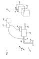
- Fig. 1 shows a schematic representation of an embodiment of a system according to the invention for determining the position and orientation of a camera relative to a real object.
- the system 10 includes a sensor system 20 having at least one movable part 22 fixed to a fixed part 21 via a movable hinge.
- the sensor system can also have other moving parts, each with each other via joints o.ä. are connected, or may have one or more optical tracking systems, which couple the individual parts of the sensor system.
- the movable part 22 in the form of a measuring arm thus formed is connected in the present example via an adapter device 24 to at least one measuring probe 23, which is suitable for being brought into contact with at least one part of a real object 12.
- the sensor system can be designed in many ways, and in particular can also be implemented as an optical sensor system.
- a camera 11, which is arranged on the measuring arm 22 of the sensor system 20, serves to generate an image.
- the camera 11 may be provided with a light source for illuminating the real object.
- Position data is generally understood to mean data that allows conclusions about the position and orientation of the relevant component. For example, only raw position data from individual sensor components and dimensions of components are supplied by the sensor system, which are processed only in an external computer to actual, evaluable for the application position data.
- This calculation of the camera pose is made in the present case by an external processing device 14 which can be coupled to the interface device 26 in the form of a computer.
- the camera pose thus calculated serves for the context-correct mixing of a virtual data model 13 with the image generated by the camera 11, which image is displayed on an external display device 15 in the form of a screen.
- the computer 14 is connected both to the sensor system 20 and to the camera 11 in order, on the one hand, to obtain the required parameters for determining the camera pose and, on the other hand, the image of the camera 11.
- the virtual data model 13 is stored in the computer 14 and due to its calculations is superimposed on the monitor 15 with the image of the camera with the real object 12.
- the goal is to determine the pose, ie the position and orientation, of the camera 11 relative to the object coordinate system 40 of the real examination object 12 and thus to be able to superimpose a virtual geometry in the form of the data model 13 on the real object 12.
- the virtual geometry 13 may be a CAD design of a component and the real object 12 may be a real prototype created from the CAD design.
- a sensor coordinate system 30 (so-called sensor world coordinate system) is set up as the reference system of the sensor system.
- Fig. 2 shows a schematic representation of the system according to Fig. 1 with visualized transformations between the individual components.
- different sensors or sensor combinations of a sensor system 20 can be used.
- highly accurate mechanical measuring arms can be used, illustrated schematically in the form of the measuring arms 21, 22.
- the pose does not result directly from the sensor measurement result, but additionally results from the transformation 32 of the sensor world coordinate system 30 to the object coordinate system 40 of the real object 12 and the transformation 62 between the camera coordinate system 60 and the sensor head coordinate system 70, the sensor head being formed by the probe 23.
- the transformations 32 and 62 are preferably stored permanently in the computer 14 or in the sensor system 20. Therefore, they do not always have to be regenerated, but are called up to calculate the pose.
- a sensor system is used according to the invention in combination with a camera, as illustrated by the sensor system 20 and the camera 11.
- a sensor system 20 is used, in which the real object 12 is touched by means of so-called probe 23.
- geometrical properties such as, for example, surfaces or bores are approached and touched by the operator of the sensor system 20 as a starting point (so-called calibration process) and thus their position in the sensor world coordinate system 30 is determined. Consequently, the transformation 32 between object coordinate system 40 and sensor world coordinate system 30 is determined in this way during the so-called calibration.
- This is set in a fixed relation to the fixed part 21 of the sensor system 20 and to the real object 12.
- the fixed part 21 is in fixed relation to the real object 12.
- the transformation 31 between sensor head coordinate system 70 and sensor world coordinate system 30 supplies the sensor system 20.
- the measuring arm 22 of the sensor system with the camera 11 is positioned in such a way that the image can be generated by the camera.
- position data of the sensor system 20 with respect to the real object 12 are generated to form the transformation 31, and the position and orientation of the camera 11 are determined on the basis of the position data.
- the transformation 62 for determining the camera pose relative to the sensor head 23 is additionally required.
- the position of the probe 23 with respect to the sensor world coordinate system 30 and the position data of the probe 23 with respect to the sensor world coordinate system 30 are determined are output in the form of the transformation 31.
- the position and orientation of the camera 11 relative to the real object 12 is then based on the transformation 31, the position of the sensor world coordinate system 30 with respect to the real object 12 (transformation 32), and based on the position of the camera 11 with respect to the probe 23 (transformation 62).
- the pose can then be determined by calculation methods known per se.
- the calculations take place on the computer 14, which is connected to the corresponding sensors including the camera 11 and is able to generate virtual images from 3D data taking into account the camera parameters, pose and display surface, with a camera image, which advantageously due to the camera data has been corrected and mixed on a display device 15 and / or a head-mounted screen system 18, 19 (FIG. Fig. 3a or 3b).
- the determination of the camera parameters per se is known from the prior art.
- the correction of a camera image is known per se due to the camera parameters.
- the transmission of the camera data can advantageously be done by means of digital transmission standards, such as the IEEE 1394 standard.
- the transformation 61 between the camera coordinate system 60 and the coordinate system 51 of the data model 13 (in the home position 13-1), and the displacement transformation 53 between the coordinate system 51 in the home position 13-1 and the coordinate system 52 of the data model 13 in the shifted position 13-2 are determined.
- a corresponding computer program is deposited, which according to the described method, the determination of the position and orientation of the camera 11 based on the respective position data.
- the interchangeable probe 23 and the camera 11 connects to each other, now a very precise superposition can now be performed very easily.
- the adapter device 24 according to the invention, by means of mechanical methods of the prior art, to be designed so that different probes 23 with high Repeat accuracy can be used and secured.
- the buttons 23 are equipped with options, so that the adapter device 24, which can be equipped with appropriate sensors, automatically detects the button and the computer 14 can automatically retrieve corresponding corrected button information.
- the adapter device 24 can advantageously be supported by a tripod or similar mechanical means (cable, etc.), or the operator can be relieved.
- Fig. 3 shows a schematic representation of further embodiments of a system 10 according to the invention for determining the position and orientation of a camera or a display device relative to a real object, each with visualized transformations between the individual components.
- the system 10 in turn comprises a sensor system 20 with at least one first movable part in the form of the measuring arm 22, to which at least one measuring probe 23 can be coupled.
- a second movable part 25 of the sensor system 20 is provided, which in the present case is not mechanically connected to the measuring arm 22, so to speak is an independently movable sensor head 25.
- the sensor head 25 can only be an arbitrary marking.
- a tracking system 16 for example an optical tracking system, which is arranged on the measuring arm 22 of the sensor system, serves for tracking ("tracking") of the sensor head 25.
- the tracking system comprises a camera with a computer system, which is e.g. detects and tracks a marker of the sensor head 25.
- the transformation 81 between tracking system coordinate system 80 and sensor head coordinate system 90 (e.g., defined by markers) is determined.
- the "hand-eye calibration” can be used.
- the transformation 91 between sensor head coordinate system 90 and camera coordinate system 100 is known.
- the transformation 101 denotes the transformation between the camera coordinate system 100 and the coordinate system 51 of the data model 13.
- a camera 17 is disposed on the sensor head 25 of the sensor system and is suitable and positioned to generate an image that includes at least a portion of the real object 12.
- the image generated by the camera is visualized on a head mounted display (HMD) 18, which is carried by the user 9 upside down and which also displays the virtual information.
- the tracking system 16 also referred to as so-called outside-in-sensor system or the measuring arm 22 is arranged such that the camera 17 is detected by the tracking system 16.
- Camera 17 and display 18 form a so-called. See-through video system in which in front of the user's eye, a video screen (display 18) is located, are mixed on the real and virtual visual impressions.
- An interface device 26 serves to output first position data (in particular for calculating the transformation 31) of the sensor system 20 with respect to the real object 12 and second position data (in particular for calculating the transformation 81) of the tracking system 16 for determining the position and orientation of the camera 17 relative to the real object 12 by the processing device 14 that can be coupled to the interface device 26.
- This data is used when mixing a virtual data model 13 with the image generated by the camera 17.
- the interface device 26 may be wireless or wired, and may also include multiple individual interfaces, even at different locations of the sensor system.
- the tracking system 16 can also be connected directly to the computer 14 via a corresponding interface of the interface device.
- the outside-in sensor system 16 views a so-called out-side-in-sensor head 25 and dynamically determines the pose to the sensor head coordinate system 90.
- a suitable outside-in sensor system 16 may be an optical tracking system with one or more cameras, for which optical markers represent the sensor head 25.
- methods are also conceivable which determine the pose via time or angle measurements.
- the transformation 91 of the sensor head 25 to the camera 17 advantageously mounted on the head-mounted screen system 18 the viewer 9 can be superimposed on a virtual object 13 which is in a pose that is as correct as possible relative to the real object 12.
- the camera 17 is a stereo camera system and the HMD is a stereoscopic image.
- the HMD is replaced by a portable monitor equipped with a camera and an outside-in sensor head.
- a display device 19 in the form of a semipermeable head mounted display is arranged directly on the sensor head 25 of the sensor system.
- optical see-through the mixing is done by a so-called optical mixer - a semi-transparent display device in front of the user's eye, where the real world can be seen on the transparency of the device and the superimposition of virtual information on the projection Presentation device happens.
- the camera 17 can therefore be omitted.
- the position determination of the display device 19 is analogous to the system according to Fig. 3a (as explained with respect to the local camera 17).
- the transformation 91 between the sensor head coordinate system 90 and the display coordinate system 110 is known.
- the transformation 111 designates the transformation between the display coordinate system 110 and the coordinate system 51 of the data model 13.
- see-through calibration such as in the printed document US2002 / 0105484 A1 described.
- Fig. 4 shows a further advantageous construction, in which a display device 15 for displaying the image of the camera 11 is attached to the adapter device 24.
- the computer 14 is attached to the adapter device 24.
- the camera 11, the computer 14 and the display device 15 are designed as an integrated device which is attached to the adapter device 24.
- it is an integrated solution (eg compact computer with screen and integrated camera, as basically known from the prior art).
- Fig. 5 shows a flowchart about a procedure of a method in an augmented reality system, in which the inventive concept is implemented.
- Fig. 5 an advantageous sequence of a component overlay by means of the system structure Fig. 1 to 3 ,
- a first step it is ensured that the object 12 and the sensor world coordinate system 30 are in a fixed relationship to one another (step 1.0). Thereafter, the calibration procedure is carried out by means of the measuring probe 23 (step 2.0) and the result is stored in the computer 14.
- the calibration process advantageously consists of the identification of useful measurement geometries on the object 12 (for example holes or surfaces). For different Einmessgeometrien different stylus shapes (for example, tip or ball) may be advantageous. In order to avoid probe changes, it is useful to key in the calibration geometries sorted according to probe shapes. In order to be able to perform a calibration process, the possible algorithm must know both the actual property relative to the sensor world coordinate system 30 and the corresponding desired property in the object correlation system 40.
- the user can select a part (e.g., a point, an edge, or an area) of a CAD model, for example, by a mouse click.
- a part e.g., a point, an edge, or an area
- an algorithm from the CAD topology of the environment of the selected CAD part and the selected calibration algorithm determines the order of the measurement programs according to a rule set, where meaningful measurement programs are arranged at the top of a selection after the rule set.
- Another possibility is that the user does not have to select a calibration algorithm at the beginning, but only selects CAD parts, and then a rule set globally both the calibration algorithm and the individual measurement programs, as well as the selection of the buttons and the order of Determines measuring programs and consequenttastenden CAD parts. If no CAD model is available, target properties with restrictive degrees of freedom can also be specified directly (step 2.1).
- the calibration algorithm can determine the transformation 32 (steps 2.1.1 and 2.1.2).
- complementary design elements can now be virtually attached to a prototype vehicle as a real object 12, or a target / actual comparison of components can be carried out (step 3.0).
- one or more virtual objects for example described by the Virtual Reality Modeling Language (VRML)
- VRML Virtual Reality Modeling Language
- the material properties of the digital models can be changed (step 3.2).
- a measurement of a distance between a part of the real object of interest and a corresponding part of the virtual data model can take place, for example, by the user selecting a part of the virtual model, such as a point of interest, in the image by determining a first point and then the user determining a second point, a corresponding part of the real object is selected by means of the measuring probe, wherein the distance to be determined is the distance between the first and second point.
- This selection order is also reversible, i. first, a point of interest on the real object in reality can be selected by means of the measuring probe and subsequently a corresponding point in the virtual model.
- step 4.1 It is possible to communicate with participants to save the current screen state (step 4.1, for example as JPEG).
- a quanititative statement is to be made, there is the possibility for the user on the one hand, for example by a control element, for example a mouse wheel, of individual degrees of freedom of the correction transformation 53 (FIG. Fig. 2 ) to the superposed virtual geometry 13 until the geometry 13 superimposes the real part 12 as correctly as possible (step 4.2a).
- the correction transformation 53 then gives a statement about the deviation.
- step 4.2b there is the possibility of a computer-aided determination of the deviation.
- an optimization method varies the correction transformation 53 and measures the remaining deviation, which enters into the cost function of the optimization method.
- the measurements of the cost functions can be 2-dimensional or 3-dimensional. 3-dimensional data can be analyzed by additional 3D sensors, such as a laser scanner, are determined or obtained by means of known from the prior art 3D reconstruction algorithms that use different camera views and the associated tracking data.
Description
Die Erfindung betrifft ein Verfahren und ein System zur Ermittlung der Position und Orientierung einer Kamera oder einer Darstellungsvorrichtung relativ zu einem realen Objekt zur Verwendung bei der Vermischung eines virtuellen Datenmodells mit einem von der Kamera bzw. der Darstellungsvorrichtung generierten Abbild, welches wenigstens einen Teil des realen Objekts beinhaltet.The invention relates to a method and a system for determining the position and orientation of a camera or a display device relative to a real object for use in the mixing of a virtual data model with an image generated by the camera or the display device, which at least part of the real Object includes.
Ein derartiges Verfahren und ein derartiges System sind im Stand der Technik insbesondere im Zusammenhang mit sogenannten Augmented Reality Systemen bekannt. Diese erlauben die Überlagerung von Computer-generierten, virtuellen Informationen mit Seheindrücken der realen Umgebung. Hierzu werden die Seheindrücke der realen Welt vorzugsweise mittels auf dem Kopf getragenen halbdurchlässigen Datenbrillen mit virtuellen Informationen vermischt. Die Einblendung der virtuellen Informationen bzw. Objekte kann dabei kontextabhängig, d.h. angepasst und abgeleitet von der jeweilig betrachteten realen Umgebung ausgeführt sein. Als virtuelle Information kann grundsätzlich jede Art von Daten wie Texte, Abbildungen etc. verwendet werden. Die reale Umgebung kann mit einer, beispielsweise auf dem Kopf des Anwenders getragenen, Kamera erfasst werden. Der Anwender hat durch die Überlagerung von virtueller und realer Umgebung die Möglichkeit, Soll-Ist-Abgleiche einfach durchzuführen. Bei einer Kopfbewegung des Anwenders eines Augmented Reality Systems müssen sämtliche künstlichen Objekte dem sich ändernden Sichtfeld nachgeführt werden.Such a method and such a system are known in the prior art, in particular in connection with so-called augmented reality systems. These allow the overlay of computer-generated, virtual information with visual impressions of the real environment. For this purpose, the visual impressions of the real world are preferably mixed with virtual information by means of semipermeable data glasses worn on the head. The insertion of the virtual information or objects can be context-dependent, i. adapted and derived from the respective considered real environment be executed. In principle, any type of data such as texts, images etc. can be used as virtual information. The real environment can be detected with a camera, for example worn on the user's head. By overlaying the virtual and the real environment, the user has the option of simply carrying out target / actual comparisons. When the user of an augmented reality system moves his head, all artificial objects must be tracked to the changing field of view.
Während eines Initialisierungsvorgangs wird beispielsweise ein Objekt der realen Umgebung mit der Kamera in Beziehung gesetzt. Dadurch kann ein Kamerabild der realen Umgebung zugeordnet werden. Die reale Umgebung kann eine komplexe Vorrichtung und das erfasste Objekt kann ein markantes Element der Vorrichtung sein. Während eines folgenden sogenannten Tracking-Vorgangs, der den eigentlichen Arbeitsvorgang repräsentiert während beispielsweise ein Anwender des Systems kontextabhängige Information an einer gewünschten Position in Bezug zur realen Umgebung in einer verwendeten Anzeigeeinrichtung eingeblendet erhält, wird das eingeblendete virtuelle Datenmodell der Bewegung des Benutzers und einer damit einhergehenden Veränderung der Sicht auf die reale Welt nachgeführt.For example, during an initialization process, an object of the real world is related to the camera. As a result, a camera image can be assigned to the real environment. The real environment may be a complex device and the detected object may be a distinctive element of the device. During a following so-called tracking process, which represents the actual operation while, for example, a user of the system receives context-dependent information displayed at a desired position in relation to the real environment in a used display device, the displayed virtual data model of the movement of the user and a concomitant change in the view of the real world.
Weiterhin ist aus dem Stand der Technik die Augmented Reality-Technologie in Verbindung mit einer Überlagerung virtueller Modelle mit der Realität zum Zwecke der Überprüfung der Korrektheit der Modelle bzw. der nach der Spezifikation hergestellten Realität bekannt. Anwendungsbereiche sind zum Beispiel die Fabrikplanung, etwa wie in
Die Dokumente
Grundsätzlich geht es bei solchen Augmented Reality Systemen oder Verfahren um die Erkennung der Kamerapose relativ zur Realität. Die Kamerapose ist die Position und Orientierung der Kamera im Raum. Die Realität liegt meist in irgendeiner Form als Modell vor, beispielsweise als 3D-Modell, welches die geometrischen Eigenschaften der Realität oder eines Teils der Realität umschreibt. Das 3D-Modell kann beispielsweise aus einer Konstruktionszeichnung, etwa einem CAD-Dokument, gewonnen werden. Das reale Objekt wird üblicherweise in Bezug zu einem Objektkoordinatensystem gesetzt, die Kamera wiederum in Bezug zu einem Kamerakoordinatensystem. Hierbei ist insbesondere die genaue Ermittlung der Transformation zwischen Objektkoordinatensystem und Kamerakoordinatensystem zur Bestimmung der Kamerapose im allgemeinen problematisch.Basically, such augmented reality systems or methods involve the detection of the camera pose relative to reality. The camera pose is the position and orientation of the camera in the room. The reality is usually in some form as a model, for example, as a 3D model, which circumscribes the geometric properties of reality or a part of reality. For example, the 3D model can be obtained from a design drawing, such as a CAD document. The real object is usually set in relation to an object coordinate system, the camera in turn in relation to a camera coordinate system. In particular, the exact determination of the transformation between the object coordinate system and the camera coordinate system for determining the camera pose is problematic in general.
Aufgabe der Erfindung ist es, ein System und Verfahren der eingangs genannten Art bereitzustellen, welche jeweils eine weitgehend genaue Darstellung virtueller Objekte bezüglich der Realität ermöglichen.The object of the invention is to provide a system and method of the type mentioned, which each allow a largely accurate representation of virtual objects with respect to reality.
Diese Aufgabe wird gelöst durch ein Verfahren gemäß den Merkmalen des Patentanspruchs 1 und gemäß den Merkmalen des Patentanspruchs 8. Weiterhin wird die Aufgabe gelöst durch ein System gemäß den Merkmalen des Patentanspruchs 14 und gemäß den Merkmalen des Patentanspruchs 21. Weiterhin betrifft die Erfindung ein Computerprogrammprodukt nach Patentanspruch 24.This object is achieved by a method according to the features of
Anwendungsbeispiele der Erfindung umfassen insbesondere die Fabrikplanung, den Prototypenbau oder Versuchsbau in der Produktentwicklung (z.B. auch in Crashtests für die Fahrzeugentwicklung), und die Abnahme im Anlagenbau. Hierbei ist insbesondere ein Abgleich der Qualität eines virtuellen Modells gegenüber dem realen Objekt beziehungsweise eines realen Objekts gegenüber dem virtuellen Modell ermöglicht.Application examples of the invention include, in particular, factory planning, prototype construction or experimental design in product development (eg also in crash tests for vehicle development), and acceptance in plant construction. in this connection In particular, a comparison of the quality of a virtual model with respect to the real object or a real object compared to the virtual model is made possible.
Mögliche Anwendungen des Systems und des Verfahrens gemäß der Erfindung schließen insbesondere Anwendungen der Augmented Reality Technologie in den Bereichen Service und Wartung, Anwendungen in der Produktion sowie allgemein Anwendungen im mobilen Umfeld ein. Der Vorteil, der sich aus der Anwendung des erfindungsgemäßen Verfahrens und des erfindungsgemäßen Systems ergibt, ist insbesondere eine hohe Genauigkeit bei der Ermittlung einer Transformation zwischen Objektkoordinatensystem und Kamerakoordinatensystem zur Bestimmung einer genauen Kamerapose gegenüber dem realen Objekt mit Hilfe des Sensorsystems, so dass das virtuelle Datenmodell weitgehend genau mit der Realität überlagert werden kann bzw. genaue relative Abweichungen zwischen Datenmodell und Realität feststellbar sind.Possible applications of the system and method according to the invention include, in particular, applications of augmented reality technology in the areas of service and maintenance, applications in production and in general applications in the mobile environment. The advantage resulting from the application of the method according to the invention and of the system according to the invention is, in particular, a high degree of accuracy in determining a transformation between the object coordinate system and the camera coordinate system for determining an accurate camera pose with respect to the real object with the aid of the sensor system, such that the virtual data model can be superimposed exactly with the reality and accurate relative deviations between data model and reality can be determined.
Insbesondere betrifft die Erfindung ein Verfahren zur Ermittlung der Position und Orientierung einer Kamera relativ zu einem realen Objekt der eingangs genannten Art mit folgenden Schritten: Anordnen der Kamera auf einem beweglichen Teil eines Sensorsystems, das mit wenigstens einem Messtaster koppelbar ist, welcher geeignet ist, mit wenigstens einem Teil des realen Objekts in Berührung zu kommen, Positionieren des beweglichen Teils des Sensorsystems mit aufgebrachter Kamera in der Weise, dass das Abbild durch die Kamera generierbar ist, Generieren von Positionsdaten des Sensorsystems in Bezug auf das reale Objekt, und Bestimmung der Position und Orientierung der Kamera auf Basis der Positionsdaten des Sensorsystems.In particular, the invention relates to a method for determining the position and orientation of a camera relative to a real object of the type mentioned above with the following steps: arranging the camera on a movable part of a sensor system which can be coupled to at least one probe, which is suitable with positioning the movable part of the camera-mounted sensor system in such a way that the image can be generated by the camera, generating position data of the sensor system with respect to the real object, and determining the position and Orientation of the camera based on the position data of the sensor system.
Um die Kamerapose idealerweise in Echtzeit zu ermitteln, können unterschiedliche Sensoren oder Sensorkombinationen eingesetzt werden. Vorteilhafterweise können hochgenaue mechanische Messarme mit Messtastern eingesetzt werden, die dazu dienen, die relative Sensorposition einzumessen. Somit kann ein hochgenaues Sensorsystem eingesetzt werden, um eine weitgehend genaue Transformation zwischen Objekt- und Kamerakoordinatensystem als Ausgangspunkt für die Bestimmung der Kamerapose zu ermitteln.In order to determine the camera pose ideally in real time, different sensors or sensor combinations can be used. Advantageously, highly accurate mechanical measuring arms can be used with probes, which serve to gauge the relative sensor position. Thus, a highly accurate sensor system can be used to determine a largely accurate transformation between the object and camera coordinate system as a starting point for the determination of the camera pose.
Insbesondere wird ein fester Teil des Sensorsystems in einem festen Bezug zum realen Objekt angeordnet und ein Sensorkoordinatensystem als Bezugssystem des Sensorsystems eingerichtet. Weiterhin erfolgt eine Bestimmung der Position des Sensorkoordinatensystems in Bezug auf das reale Objekt. Vorteilhaft erfolgt die Bestimmung der Position des Sensorkoordinatensystems in Bezug auf das reale Objekt dadurch, dass der Messtaster in wenigstens einem Einmessvorgang mit wenigstens einem Teil des realen Objekts in Berührung gebracht wird.In particular, a fixed part of the sensor system is arranged in a fixed relationship to the real object and a sensor coordinate system as a reference system set up the sensor system. Furthermore, a determination of the position of the sensor coordinate system with respect to the real object takes place. The determination of the position of the sensor coordinate system with respect to the real object advantageously takes place in that the probe is brought into contact with at least one part of the real object in at least one calibration process.
In einer Ausführungsform der Erfindung wird der wenigstens eine Einmessvorgang gemäß einem von mehreren hinterlegten Einmessalgorithmen vorgenommen. Beispielsweise wird vom Benutzer wenigstens ein Teil eines CAD-Modells des realen Objekts ausgewählt, wobei auf Grundlage der Auswahl ein Einmess-Algorithmus für den wenigstens einen Einmessvorgang und wenigstens ein Messprogramm ausgewählt wird.In one embodiment of the invention, the at least one calibration process is performed according to one of several stored calibration algorithms. For example, at least part of a CAD model of the real object is selected by the user, wherein on the basis of the selection a calibration algorithm for the at least one calibration process and at least one measurement program is selected.
In einem weiteren Aspekt der Erfindung betrifft diese ein Verfahren zur Ermittlung der Position und Orientierung einer Kamera oder einer Darstellungsvorrichtung relativ zu einem realen Objekt der eingangs genannten Art mit folgenden Schritten: Anordnen eines Trackingsystems auf einem ersten beweglichen Teil eines Sensorsystems, das mit wenigstens einem Messtaster koppelbar ist, welcher geeignet ist, mit wenigstens einem Teil des realen Objekts in Berührung zu kommen, und Anordnen der Kamera bzw. der Darstellungsvorrichtung in festem Bezug zu einem zweiten beweglichen Teil des Sensorsystems.In a further aspect of the invention, this relates to a method for determining the position and orientation of a camera or a display device relative to a real object of the type mentioned above with the following steps: arranging a tracking system on a first movable part of a sensor system, with at least one probe can be coupled, which is suitable to come into contact with at least a part of the real object, and arranging the camera or the display device in fixed relation to a second movable part of the sensor system.
Der erste bewegliche Teil des Sensorsystems wird derart positioniert, dass der zweite bewegliche Teil des Sensorsystems vom Trackingsystem erfassbar ist. Der zweite bewegliche Teil des Sensorsystems mit der Kamera bzw. Darstellungsvorrichtung wird in der Weise positioniert, dass das Abbild durch die Kamera bzw. die Darstellungsvorrichtung generierbar ist. Es werden sodann erste Positionsdaten des Sensorsystems in Bezug auf das reale Objekt und zweite Positionsdaten des Trackingsystems in Bezug auf den zweiten beweglichen Teil des Sensorsystems generiert. Die Bestimmung der Position und Orientierung der Kamera bzw. der Darstellungsvorrichtung erfolgt auf Basis der ersten und zweiten Positionsdaten.The first movable part of the sensor system is positioned such that the second movable part of the sensor system is detectable by the tracking system. The second movable part of the sensor system with the camera or presentation device is positioned in such a way that the image can be generated by the camera or the display device. First position data of the sensor system with respect to the real object and second position data of the tracking system with respect to the second movable part of the sensor system are then generated. The determination of the position and orientation of the camera or the display device is based on the first and second position data.
Dieser Aspekt reflektiert eine vorteilhafte Umsetzung des erfindungsgemäßen Konzepts dahingehend, dass die erfindungsgemäße Idee auch für den Einsatz sogenannter Head Mounted Displays (HMDs) verwendet werden kann. Beispielsweise ist der zweite bewegliche Teil des Sensorsystems vom ersten beweglichen Teil unabhängig bewegbar und wird vom Trackingsystem des ersten beweglichen Teils erfasst. Damit ist eine Kopplung zwischen mobiler Kamera bzw. Darstellungsvorrichtung (z.B. Head Mounted Display) und Sensorsystem derart bewerkstelligt, dass sich die Pose der Kamera bzw. Darstellungsvorrichtung unter Benutzung der genauen Einmessparameter des Sensorsystems relativ zum realen Objekt berechnen läßt, ohne an das Sensorsystem mechanisch gebunden zu sein. Aus der Kombination von mechanischem Sensor-Messsystem mit einem Trackingsystem, beispielsweise einem optischen Trackingsystem, welches am Sensorkopf des mechanischen Sensorsystems befestigt ist und die Kamera bzw. Darstellungsvorrichtung "trackt" (nachverfolgt), ergibt sich ein Gesamtsystem, welches eine höhere Reichweite und einen leichteren Sensorkopf besitzt kombiniert mit einer weitgehend genauen Ermittlung der Pose.This aspect reflects an advantageous implementation of the inventive concept to the effect that the inventive idea can also be used for the use of so-called head mounted displays (HMDs). For example, the second movable part of the sensor system is movable from the first one Part independently movable and is detected by the tracking system of the first moving part. In order for a coupling between the mobile camera or display device (eg Head Mounted Display) and sensor system is accomplished such that the pose of the camera or display device can be calculated using the exact calibration parameters of the sensor system relative to the real object without being mechanically bound to the sensor system to be. From the combination of mechanical sensor measuring system with a tracking system, for example, an optical tracking system, which is attached to the sensor head of the mechanical sensor system and "tracking" the camera or display device, results in a total system, which has a higher range and a lighter Sensor head combines with a largely accurate determination of the pose.
Insbesondere kann nach dem Eintasten mittels des Messtasters über die Transformation zwischen Trackingsystem und Objektkoordinatensystem die Transformation zwischen Trackingsystem und zweitem beweglichen Teil des Sensorsystems und die Transformation zwischen dem zweiten beweglichen Teil des Sensorsystems und der Kamera bzw. der Darstellungsvorrichtung dynamisch eine Pose der Kamera bzw. der Darstellungsvorrichtung, die mit dem zweiten beweglichen Teil des Sensorsystems verbunden ist, berechnet werden.In particular, after the keying by means of the probe via the transformation between tracking system and object coordinate system, the transformation between the tracking system and the second moving part of the sensor system and the transformation between the second movable part of the sensor system and the camera or the display device dynamically pose the camera or the Representation device, which is connected to the second movable part of the sensor system can be calculated.
In einer Ausführungsform ist das Trackingsystem als ein mechanisches Trackingsystem oder ein optisches Trackingsystem ausgeführt. Optische Mess-oder Trackingsysteme haben in diesem Zusammenhang den Vorteil, dass sie einen leichten, ergonomisch einfach verwendbaren und unabhängig bewegbaren Sensorkopf ermöglichen, der beispielsweise auf dem Kopf getragen werden kann. Allerdings liefert der Sensorkopf nur dort gültige Werte, wo er von den optischen Sensoren des Trackingsystems gesehen wird. Der Sensorkopf mechanischer Messsysteme ist schwerer und hat eine geringere Reichweite. Allerdings kann er auch an schwieriger zugängigen Stellen geführt werden (zum Beispiel der Fahrzeuginnenraum).In one embodiment, the tracking system is implemented as a mechanical tracking system or an optical tracking system. Optical measuring or tracking systems have the advantage in this context that they allow a lightweight, ergonomically easy to use and independently movable sensor head, which can be worn, for example, on the head. However, the sensor head provides only valid values where it is seen by the optical sensors of the tracking system. The sensor head of mechanical measuring systems is heavier and has a shorter range. However, it can also be routed to difficult-to-reach places (for example, the vehicle interior).
In einer Ausführungsform der Erfindung wird eine Güte der Übereinstimmung des virtuellen Datenmodells und des realen Objekts bestimmt, inbesondere erfolgt eine Vermessung wenigstens eines Abstandes zwischen wenigstens einem Teil des realen Objekts und wenigstens einem Teil des virtuellen Datenmodells. Beispielsweise wird die Bestimmung der Güte der Übereinstimmung des virtuellen Datenmodells und des realen Objekts unter Verwendung eines kantenbasierten oder flächenbasierten Trackingverfahrens durchgeführt.In one embodiment of the invention, a quality of the match of the virtual data model and the real object is determined, in particular a measurement of at least one distance between at least a part of the real object and at least a part of the virtual data model. For example, determining the goodness of the match of the virtual Data model and the real object using an edge-based or surface-based tracking method performed.
Eine Vermessung wenigstens eines Abstandes zwischen wenigstens einem Teil des realen Objekts und wenigstens einem Teil des virtuellen Datenmodells kann dadurch erfolgen, dass vom Benutzer ein Teil des virtuellen Modells im Abbild oder des realen Objekts in der Realität mittels des Messtasters unter Bestimmung eines ersten Punkts ausgewählt wird und anschließend vom Benutzer unter Bestimmung eines zweiten Punkts ein korrespondierendes Teil des realen Objekts mittels des Messtasters bzw. des virtuellen Modells im Abbild ausgewählt wird, wobei der zu bestimmende Abstand der Abstand zwischen dem ersten und zweiten Punkt ist.A measurement of at least one distance between at least one part of the real object and at least one part of the virtual data model can take place in that the user selects a part of the virtual model in the image or of the real object in reality by means of the measuring probe while determining a first point and then the user, selecting a second point, selects a corresponding part of the real object by means of the probe or virtual model in the image, the distance to be determined being the distance between the first and second points.
Die Bestimmung der Güte der Übereinstimmung des virtuellen Datenmodells und des realen Objekts kann den Schritt beinhalten, dass durch den Benutzer oder durch einen implementieren Algorithmus ein Abgleich bei der Vermischung des realen Objekts und des virtuellen Datenmodells vorgenommen wird, bis wenigstens ein Teil des Datenmodells einen korrespondierenden Teil des realen Objekts weitgehend korrekt überlagert, wobei das Maß für den vorgenommenen Abgleich als Basis für eine Aussage über die Güte der Übereinstimmung verwendet wird.The determination of the goodness of the match of the virtual data model and the real object may include the step of matching the real object and the virtual data model by the user or by an implemented algorithm until at least a part of the data model has a corresponding one Part of the real object is largely correctly superimposed, wherein the measure of the alignment is used as the basis for a statement about the quality of the match.
Insbesondere ermöglicht die Erfindung auch, eine relativ genaue Ungenauigkeitsinformation, insbesondere eine Unsicherheitsinformation, bei der Positionierung des Datenmodells relativ zum realen Objekt zu generieren, wie in
Eine vorteilhafte Ausprägung des erfindungsgemäßen Systems sieht vor, dass die Kamera bzw. das Trackingsystem an einer Adaptereinrichtung angebracht ist, die eine mechanische Verbindung zwischen Kamera/Trackingsystem und dem Messtaster herstellt. Durch den Einsatz eines Adapters, der Messtaster und Kamera/Trackingsystem miteinander verbindet, kann nun sehr einfach eine hochgenaue Überlagerung durchgeführt werden. Insbesondere ist die Adaptereinrichtung so gestaltet, dass unterschiedliche Messtaster wiederholbar bzw. austauschbar einsetzbar und wieder entfernbar sind. Vorteilhaft ist die Adaptereinrichtung so gestaltet, dass bei Verbindung mit einem Messtaster dieser automatisch von dem Sensorsystem erkennbar ist.An advantageous embodiment of the system according to the invention provides that the camera or the tracking system is attached to an adapter device which establishes a mechanical connection between the camera / tracking system and the probe. By using an adapter that connects the probe and the camera / tracking system, it is now very easy to perform a highly accurate overlay. In particular, the adapter device is designed such that different measuring probes can be used repeatably or interchangeably and removed again. Advantageously, the adapter device is designed so that when connected to a probe this is automatically recognizable by the sensor system.
Eine andere Ausführungsform sieht vor, dass eine Anzeigeeinrichtung, insbesondere ein Bildschirm, zur Darstellung des Abbilds der Kamera an der Adaptereinrichtung angebracht ist. Ebenso kann die Verarbeitungseinrichtung zur Berechnung der gewünschten Pose an der Adaptereinrichtung angebracht sein. Hierbei ist es z.B. vorgesehen, dass die Kamera, die Verarbeitungseinrichtung und die Anzeigeeinrichtung als integrierte Einrichtung ausgeführt sind, die an der Adaptereinrichtung angebracht ist, welche wiederum eine mechanische Verbindung zwischen dem Messtaster und integrierter Einrichtung herstellt.Another embodiment provides that a display device, in particular a screen, is mounted on the adapter device for displaying the image of the camera. Likewise, the processing device for calculating the desired pose can be attached to the adapter device. Here it is e.g. provided that the camera, the processing device and the display device are designed as an integrated device, which is attached to the adapter device, which in turn produces a mechanical connection between the probe and integrated device.
Weitere vorteilhafte Ausführungsformen und Weiterbildungen der Erfindung sind den Unteransprüchen zu entnehmen.Further advantageous embodiments and modifications of the invention can be found in the dependent claims.
Die Erfindung wird im folgenden anhand der in der Zeichnung dargestellten Figuren, die vorteilhafte Ausführungsformen der Erfindung darstellen, näher erläutert.
- Fig. 1
- zeigt in schematischer Darstellung eine Ausführungsform eines erfindungsgemäßen Systems zur Ermittlung der Position und Orientierung einer Kamera relativ zu einem realen Objekt,
- Fig. 2
- zeigt in schematischer Darstellung das
System gemäß Figur 1 mit visualisierten Transformationen zwischen den einzelnen Komponenten, - Fig. 3
- zeigt in schematischer Darstellung weitere Ausführungsformen eines erfindungsgemäßen Systems zur Ermittlung der Position und Orientierung einer Kamera bzw. einer Darstellungsvorrichtung relativ zu einem realen Objekt mit jeweils visualisierten Transformationen zwischen den einzelnen Komponenten,
- Fig. 4
- zeigt in schematischer Darstellung eine weitere Ausführungsform eines erfindungsgemäßen Systems,
- Fig. 5
- zeigt ein Flussdiagramm über einen Ablauf eines Verfahrens in einem Augmented Reality System, in welchem das erfindungsgemäße Konzept implementiert ist.
- Fig. 1
- shows a schematic representation of an embodiment of a system according to the invention for determining the position and orientation of a camera relative to a real object,
- Fig. 2
- shows a schematic representation of the system according to
FIG. 1 with visualized transformations between the individual components, - Fig. 3
- shows a schematic representation of further embodiments of a system according to the invention for determining the position and orientation of a camera or a display device relative to a real object, each with visualized transformations between the individual components,
- Fig. 4
- shows a schematic representation of another embodiment of a system according to the invention,
- Fig. 5
- shows a flowchart about a procedure of a method in an augmented reality system, in which the inventive concept is implemented.
Weiterhin ist eine Schnittstelleneinrichtung 26 vorgesehen, um Positionsdaten des Sensorsystems 20 in Bezug auf das reale Objekt 12 auszugeben zur Bestimmung der Position und Orientierung (Pose) der Kamera 11 relativ zum realen Objekt 12, wie im folgenden noch erläutert. Unter Positionsdaten sind allgemein Daten zu verstehen, die einen Rückschluss auf die Position und Orientierung der betreffenden Komponente zulassen. Beispielsweise werden vom Sensorsystem nur Positions-Rohdaten von einzelnen Sensorkomponenten und Abmessungen von Komponenten geliefert, die erst in einem externen Rechner zu eigentlichen, für die Anwendung auswertbaren Positionsdaten verarbeitet werden.Furthermore, an
Diese Berechnung der Kamerapose wird vorliegend durch eine mit der Schnittstelleneinrichtung 26 koppelbare, externe Verarbeitungseinrichtung 14 in Form eines Rechners vorgenommen. Die so berechnete Kamerapose dient zur kontextrichtigen Vermischung eines virtuellen Datenmodells 13 mit dem von der Kamera 11 generierten Abbild, welches auf einer externen Darstellungsvorrichtung 15 in Form eines Bildschirms dargestellt wird. Dazu ist der Rechner 14 sowohl mit dem Sensorsystem 20 als auch mit der Kamera 11 verbunden, um einerseits die erforderlichen Parameter zur Ermittlung der Kamerapose und andererseits das Abbild der Kamera 11 zu erhalten. Das virtuelle Datenmodell 13 ist im Rechner 14 hinterlegt und wird aufgrund dessen Berechnungen kontextrichtig auf dem Bildschirm 15 dem Abbild der Kamera mit dem realen Objekt 12 überlagert.This calculation of the camera pose is made in the present case by an
Ziel ist es, die Pose, das heißt die Lage und Orientierung, der Kamera 11 relativ zum Objektkoordinatensystem 40 des realen Untersuchungsobjekts 12 zu bestimmen und damit in der Lage zu sein, eine virtuelle Geometrie in Form des Datenmodells 13 dem realen Objekt 12 zu überlagern. Zum Beispiel kann die virtuelle Geometrie 13 eine CAD-Konstruktion eines Bauteils sein und das reale Objekt 12 ein realer Prototyp, der aus der CAD-Konstruktion entstanden ist. Weiterhin wird ein Sensorkoordinatensystem 30 (sog. Sensorweltkoordinatensystem) als Bezugssystem des Sensorsystems eingerichtet.The goal is to determine the pose, ie the position and orientation, of the
Zur Ermittlung der Transformation 62 zwischen Sensorkopfkoordinatensystem 70 und Kamerakoordinatensystem 60 können aus dem Stand der Technik bekannte Kalibrierungsverfahren (z.B. "Hand-Eye-Kalibrierung") genutzt werden. Beispielsweise wird ein Verfahren eingesetzt, wie in
Die Ermittlung der Transformation 32 zwischen Objektkoordinatensystem 40 und Sensorweltkoordinatensystem 30 ist im allgemeinen im Bereich Augmented Reality bisher problematisch. Zur Lösung dieses Problems wird erfindungsgemäß ein Sensorsystem in Kombination mit einer Kamera eingesetzt, wie anhand des Sensorsystems 20 und der Kamera 11 veranschaulicht. Insbesondere wird ein Sensorsystem 20 eingesetzt, bei dem das reale Objekt 12 mittels sogenannter Messtaster 23 angetastet wird. Das bedeutet, dass als Ausgangspunkt (sogenannter Einmessvorgang) geometrische Eigenschaften, wie zum Beispiel Oberflächen oder Bohrungen durch den Bediener des Sensorsystems 20 angefahren und berührt werden und somit deren Lage im Sensorweltkoordinatensystem 30 ermittelt wird. Mithin wird auf diese Art beim sog. Einmessen die Transformation 32 zwischen Objektkoordinatensystem 40 und Sensorweltkoordinatensystem 30 ermittelt. Dieses wird in einem festen Bezug zum feststehenden Teil 21 des Sensorsystems 20 und zum realen Objekt 12 gesetzt. Ebenso ist der feststehende Teil 21 in festem Bezug zum realen Objekt 12. Die Transformation 31 zwischen Sensorkopfkoordinatensystem 70 und Sensorweltkoordinatensystem 30 liefert das Sensorsystem 20.The determination of the
Nach dem Einmessen wird der Messarm 22 des Sensorsystems mit aufgebrachter Kamera 11 in der Weise positioniert, dass das Abbild durch die Kamera generierbar ist. Im Zuge dessen werden Positionsdaten des Sensorsystems 20 in Bezug auf das reale Objekt 12 zur Bildung der Transformation 31 generiert und die Position und Orientierung der Kamera 11 auf Basis der Positionsdaten bestimmt. Im vorliegenden Beispiel ist zusätzlich noch die Transformation 62 zur Ermittlung der Kamerapose relativ zum Sensorkopf 23 erforderlich.After measuring, the measuring
Insbesondere folgende Schritte werden durchgeführt, um Ausgangsparameter für die Berechnung der Kamerapose zu ermitteln. Diese wird z.B. für die Augmented-Reality-Visualisierung (AR-Visualisierung) benötigt:In particular, the following steps are performed to determine output parameters for calculating the camera pose. This is e.g. needed for augmented reality visualization (AR visualization):
Beim Positionieren des Sensorsystems 20 mit aufgebrachter Kamera 11, so dass die Kamera 11 zur Erzeugung eines Abbilds das Objekt 12 erfasst, wird die Position des Messtasters 23 in Bezug auf das Sensorweltkoordinatensystem 30 bestimmt, und die Positionsdaten des Messtasters 23 in Bezug auf das Sensorweltkoordinatensystem 30 werden in Form der Transformation 31 ausgegeben. Die Position und Orientierung der Kamera 11 relativ zum realen Objekt 12 wird dann auf Basis der Transformation 31, der Position des Sensorweltkoordinatensystems 30 in Bezug auf das reale Objekt 12 (Transformation 32), und auf Basis der Position der Kamera 11 in Bezug auf den Messtaster 23 (Transformation 62) bestimmt. Grundsätzlich ergibt sich so die zur AR-Visualisierung benötigte Transformation T zwischen Kamera 11 und realem Objekt 12 zu: ![]()
![]()
Wenn die Ausgangsparameter zur Bestimmung der Kamerapose ermittelt sind, kann durch an sich bekannte Berechnungsverfahren dann die Pose ermittelt werden. Die Berechnungen finden auf dem Rechner 14 statt, der mit den entsprechenden Sensoren inklusive der Kamera 11 verbunden ist und in der Lage ist, virtuelle Bilder aus 3D-Daten unter Berücksichtigung der Kameraparameter, Pose und Darstellungsfläche zu erzeugen, mit einem Kameraabbild, welches vorteilhafterweise aufgrund der Kameradaten korrigiert wurde, zu mischen und auf einem Anzeigegerät 15 und/oder einem kopfgetragenen Bildschirmsystem 18, 19 (
Auf diese Art können die Transformation 61 zwischen Kamerakoordinatensystem 60 und Koordinatensystem 51 des Datenmodells 13 (in der Ausgangsposition 13-1), sowie die Verschiebungs-Transformation 53 zwischen Koordinatensystem 51 in der Ausgangsposition 13-1 und Koordinatensystem 52 des Datenmodells 13 in der verschobenen Position 13-2 ermittelt werden.In this way, the transformation 61 between the camera coordinate
Im Rechner 14 ist ein entsprechendes Computerprogramm hinterlegt, welches gemäß dem beschriebenen Verfahren die Bestimmung der Position und Orientierung der Kamera 11 auf Basis der jeweiligen Positionsdaten vornimmt.In the
Durch den Einsatz einer vorzugsweise starren Adaptereinrichtung 24, die austauschbare Messtaster 23 und die Kamera 11 miteinander verbindet, kann nun sehr einfach eine hochgenaue Überlagerung durchgeführt werden. Die Adaptereinrichtung 24 ist erfindungsgemäß, mittels mechanischer Methoden aus dem Stand der Technik, so zu gestalten, dass unterschiedliche Messtaster 23 mit hoher Wiederholgenauigkeit eingesetzt und gesichert werden können. Vorteilhafterweise sind die Taster 23 mit Möglichkeiten ausgestattet, so dass die Adaptereinrichtung 24, welche mit entsprechender Sensorik ausgestattet werden kann, die Taster automatisch erkennt und der Rechner 14 entsprechend korrigierte Tasterinformationen automatisch abrufen kann. Die Adaptereinrichtung 24 kann vorteilhafterweise durch ein Stativ oder ähnliche mechanische Mittel (Seilzug, etc.) gestützt werden, bzw. die Bedienperson kann entlastet werden.By using a preferably
Ein Trackingsystem 16, beispielsweise ein optisches Trackingsystem, welches auf dem Messarm 22 des Sensorsystems angeordnet ist, dient zur Nachverfolgung ("Tracken") des Sensorkopfs 25. Hierzu umfasst das Trackingsystem eine Kamera mit Rechnersystem, welche z.B. einen Marker des Sensorkopfs 25 erfasst und trackt. Dazu wird die Transformation 81 zwischen Trackingsystem-Koordinatensystem 80 und Sensorkopfkoordinatensystem 90 (z.B. definiert durch Marker) ermittelt. Zur Ermittlung der Transformation zwischen Messtaster-Koordinatensystem 70 und Trackingsystem-Koordinatensystem 80 kann wiederum die "Hand-Eye-Kalibrierung" genutzt werden. Weiterhin ist die Transformation 91 zwischen Sensorkopfkoordinatensystem 90 und Kamerakoordinatensystem 100 bekannt. Die Transformation 101 bezeichnet die Transformation zwischen Kamerakoordinatensystem 100 und Koordinatensystem 51 des Datenmodells 13.A
In der Ausführungsform nach
Eine Schnittstelleneinrichtung 26 (vgl.
Mit anderen Worten, betrachtet das Outside-In-Sensor-System 16 einen sog. Out-side-In-Sensorkopf 25 und ermittelt dynamisch die Pose zum Sensorkopfkoordinatensystem 90. Ein geeignetes Outside-In-Sensor-System 16 kann zum Beispiel ein optisches Trackingsystem mit einer oder mehreren Kameras sein, für welches optische Marker den Sensorkopf 25 darstellen. Denkbar sind aber auch Verfahren, welche die Pose über Zeit- oder Winkelmessungen ermitteln. Mittels der Transformation 91 des Sensorkopfes 25 zur vorteilhafterweise am kopfgetragenen Bildschirmsystem 18 befestigten Kamera 17 kann dem Betrachter 9 ein virtuelles Objekt 13, welches sich in einer möglichst korrekten Pose relativ zum realen Objekt 12 befindet, überlagert werden. Möglich ist, dass es sich bei der Kamera 17 um ein Stereo-Kamerasystem handelt und das HMD ein stereoskopisches Bild darstellt. Es ist ein weiterer vorteilhafter Aufbau, dass das HMD durch einen tragbaren Monitor, welcher mit einer Kamera und einem Outside-In-Sensorkopf ausgestattet ist, ersetzt wird.In other words, the outside-in
In der Ausführungsform nach
Das bezüglich
In einem ersten Schritt wird sichergestellt, dass das Objekt 12 und das Sensorweltkoordinatensystem 30 in einem festen Verhältnis zueinander stehen (Schritt 1.0). Danach wird mittels des Messtasters 23 der Einmessvorgang durchgeführt (Schritt 2.0) und das Ergebnis im Rechner 14 gespeichert. Der Einmessvorgang besteht vorteilhafterweise aus der Identifikation sinnvoller Einmessgeometrien am Objekt 12 (zum Beispiel Bohrungen oder Flächen). Für unterschiedliche Einmessgeometrien können unterschiedliche Tasterformen (zum Beispiel Spitze oder Kugel) vorteilhaft sein. Um Tasterwechsel zu vermeiden, werden sinnvollerweise die Einmessgeometrien geordnet nach Tasterformen eingetastet. Um einen Einmessvorgang durchführen zu können, muss dem möglichen Algorithmus sowohl die Ist-Eigenschaft relativ zum Sensorweltkoordinatensystem 30 bekannt sein, als auch die entsprechende Soll-Eigenschaft im Objektkorrdinatensystem 40 bekannt sein. Vorteilhafterweise kann der Benutzer, um dem System mitzuteilen, um welche Korrespondenz es sich handelt, einen Teil (zum Beispiel einen Punkt, eine Kante oder eine Fläche) eines CAD-Modells zum Beispiel durch einen Mausklick auswählen. Insbesondere bestimmt nun ein Algorithmus aus der CAD-Topologie der Umgebung des ausgewählten CAD-Teils und dem gewählten Einmessalgorithmus nach einem Regelsatz die Ordnung der Messprogramme, wobei nach dem Regelsatz sinnvolle Messprogramme oben in einer Auswahl angeordnet werden. Eine weitere Möglichkeit besteht darin, dass der Nutzer keinen Einmessalgorithmus zu Beginn auswählen muss, sondern nur CAD-Teile auswählt, und ein Regelsatz dann global sowohl den Einmess-Algorithmus, als auch die einzelnen Messprogramme, als auch die Wahl der Taster und die Reihenfolge von Messprogrammen und einzutastenden CAD-Teilen festlegt. Ist kein CAD-Modell vorhanden, können auch direkt Soll-Eigenschaften mit einschränkenden Freiheitsgraden angegeben werden (Schritt 2.1).In a first step, it is ensured that the
Ist dem Programm bekannt, welches CAD-Teil oder welche eingegebene Soll-Eigenschaft mit welchem Messprogramm eingetastet wird oder hat das Programm dies dem Benutzer, zum Beispiel visuell, mitgeteilt, kann der Nutzer, falls nicht schon eingesetzt, den gewünschten Messtaster einsetzen und das Messprogramm durchführen (zum Beispiel das Verfahren einer runden Tastkugel auf einer Ebene). Dieser Vorgang wird für jedes gewählte CAD-Teil durchgeführt. Schließlich kann der Einmess-Algorithmus die Transformation 32 bestimmen (Schritte 2.1.1 und 2.1.2).If the program knows which CAD part or which entered desired property is keyed in with which measuring program or if the program has informed the user, for example visually, the user can, if not already used, use the desired measuring probe and the measuring program (for example, moving a round stylus on a plane). This process is performed for each selected CAD part. Finally, the calibration algorithm can determine the transformation 32 (steps 2.1.1 and 2.1.2).
Nun kann die Untersuchung fortgesetzt werden. Beispielsweise können nun ergänzende Designelemente an ein Prototypenfahrzeug als reales Objekt 12 virtuell angeheftet werden oder es kann ein Soll-Ist-Vergleich von Bauteilen durchgeführt werden (Schritt 3.0). Hierzu kann eines oder mehrere virtuelle Objekte, zum Beispiel beschrieben durch die Virtual Reality Modeling Language (VRML), eingeladen werden (Schritt 3.1). Es kann, gegebenenfalls, aber auch direkt die für das Einmessen verwendete virtuelle Geometrie angezeigt werden. Vorteilhafterweise können die Materialeigenschaften der digitalen Modelle verändert werden (Schritt 3.2).Now the investigation can be continued. For example, complementary design elements can now be virtually attached to a prototype vehicle as a
Ist die visuelle Kontrolle nicht zufriedenstellend, können gegebenenfalls gezielt Abweichungen dokumentiert werden (Schritt 4.0). Eine Vermessung eines Abstandes zwischen einem interessierenden Teil des realen Objekts und einem korrespondierenden Teil des virtuellen Datenmodells kann beispielsweise dadurch erfolgen, dass vom Benutzer ein Teil des virtuellen Modells, etwa ein interessierender Punkt, im Abbild unter Bestimmung eines ersten Punkts ausgewählt wird und anschließend vom Benutzer unter Bestimmung eines zweiten Punkts ein korrespondierendes Teil des realen Objekts mittels des Messtasters ausgewählt wird, wobei der zu bestimmende Abstand der Abstand zwischen dem ersten und zweiten Punkt ist. Diese Auswahlreihenfolge ist auch umkehrbar, d.h. es kann zuerst ein interessierender Punkt am realen Objekt in der Realität mittels des Messtasters ausgewählt werden und nachfolgend ein korrespondierender Punkt im virtuellen Modell.If the visual control is unsatisfactory, deviations can be documented if necessary (step 4.0). A measurement of a distance between a part of the real object of interest and a corresponding part of the virtual data model can take place, for example, by the user selecting a part of the virtual model, such as a point of interest, in the image by determining a first point and then the user determining a second point, a corresponding part of the real object is selected by means of the measuring probe, wherein the distance to be determined is the distance between the first and second point. This selection order is also reversible, i. first, a point of interest on the real object in reality can be selected by means of the measuring probe and subsequently a corresponding point in the virtual model.
Es besteht die Möglichkeit zur Kommunikation mit Beteiligten, den aktuellen Bildschirmzustand abzuspeichern (Schritt 4.1, zum Beispiel als JPEG). Soll eine quanititative Aussage getroffen werden, besteht für den Benutzer die Möglichkeit einerseits, zum Beispiel durch ein Bedienelement, zum Beispiel ein Mausrad, einzelne Freiheitsgrade der Korrekturtransformation 53 (
Vorteile und Anwendungen des Systems und Verfahrens gemäß der Erfindung sind nochmals zusammengefasst:Advantages and applications of the system and method according to the invention are summarized again:
Derzeitige Systeme besitzen den Nachteil, dass das Herstellen des Bezugs zwischen Sensorkoordinatensystem und Objektkoordinatensystem meist unzureichend gelöst ist. Z.B betrachtet ein Trackingsystem etwa eine Markierung in der Realität (zum Beispiel an einem Fahrzeug). Vorher muss die Markierung jedoch mittels eines Messsystems bezüglich des Weltkoordinatensystems (Fahrzeugkoordinatensystems) separat eingemessen werden. Der klare Vorteil des beschriebenen Systems und Verfahrens ist daher die direkte Kombination von Einmessund Betrachtungssystem. Folgende Vorteile ergeben sich:
- Zeiteinsparung bei Überlagerungsaufgaben, da kein Wechsel zwischen Einmess- und Betrachtungswerkzeug nötig ist. Dies bezieht sich auf den physischen Wechsel und das Umschalten in der Bediensoftware.
- Einsparung von Hardwarekosten, zum Beispiel bei optischen Systemen, da teure Markierungen nur für einen kombinierten Kopf, nicht für unterschiedliche Köpfe beschafft und gepflegt werden müssen.
- Verringerung der Softwarekomplexität dadurch, dass die Software, zum Beispiel, nicht unterschiedliche optische Marker verwalten muss.
- Time savings in overlay tasks, since no change between calibration and viewing tool is necessary. This refers to the physical change and switching in the operating software.
- Saving on hardware costs, for example in optical systems, as expensive markers need only be procured and maintained for a combined head, not for different heads.
- Reducing software complexity by requiring that the software, for example, not have to manage different optical markers.
Claims (15)
- A method for merging a virtual data model (13) with an image generated by a camera (11), said image comprising at least one part of a real object (12), having the following steps:- disposing the camera (11) on a movable part (22) of a sensor system (20) which is coupled at least temporarily with at least one probe (23) which is suitable to come in contact in a calibrating process with at least one part of the real object (12),- positioning the movable part (22) of the sensor system, with the camera (11) applied, in such a manner that an image is generated by the camera, and generating position data (31) of the sensor system (20) with respect to the real object (12),- determining the position and orientation of the camera (11) relative to the real object (12) on the basis of the position data (31, 32) of the sensor system (20) and merging of a virtual data model (13), which represents a design drawing, with the image generated by the camera (11) on the basis of the position and orientation of the camera (11),- wherein the virtual data model is superimposed with the real object largely correctly and relative deviations between the virtual data model and the real object are determined.
- The method according to claim 1, having the steps of:- disposing a fixed part (21) of the sensor system (20) in a fixed relation to the real object (12) and setting up a sensor coordinate system (30) as a frame of reference of the sensor system,- determining a position (32) of the sensor coordinate system (30) with respect to the real object (12).
- The method according to claim 2, wherein
the determination of the position (32) of the sensor coordinate system (30) with respect to the real object (12) is effected by the probe (23) being brought in contact with at least one part of the real object (12) in at least one calibrating process (2.0). - The method according to claim 3, wherein
the at least one calibrating process (2.0) is performed according to one of a plurality of retained calibrating algorithms. - The method according to any of claims 1 to 4, wherein
for determination of the position and orientation of the camera (11) a determination of the position (62) of the camera (11) with respect to the probe (23) is effected by a hand-eye calibration. - A method for merging a virtual data model (13) with an image generated by a camera (17) or a display apparatus (19), said image comprising at least one part of a real object (12), having the following steps:- disposing a tracking system (16) on a first movable part (22) of a sensor system (20) which is coupled at least temporarily with at least one probe (23) which is suitable to come in contact in a calibrating process with at least one part of the real object (12),- disposing the camera (17) or the display apparatus (19), respectively, in fixed relation to a second movable part (25) of the sensor system (20),- positioning the first movable part (22) of the sensor system such that the second movable part (25) of the sensor system is detectable by the tracking system (16),- positioning the second movable part (25) of the sensor system with the camera (17) or display apparatus (19), respectively, in such a manner that an image is generated by the camera or the display apparatus, respectively, and generating first position data (31) of the sensor system (20) with respect to the real object (12) and second position data (81) of the tracking system (16) with respect to the second movable part (25) of the sensor system,- determining the position and orientation of the camera (17) or the display apparatus (19), respectively, relative to the real object (12) on the basis of the first and second position data (31, 32, 81) and merging of a virtual data model, which represents a design drawing, with the generated image on the basis of the position and orientation of the camera (17) or the display apparatus (19), respectively,- wherein the virtual data model is superimposed with the real object largely correctly and relative deviations between the virtual data model and the real object are determined.
- The method according to any of claims 1 to 6, wherein
a quality of the match of the virtual data model (13) and the real object (12) is determined, in particular a measurement of at least one distance between at least one part of the real object (12) and at least one part of the virtual data model (13) is effected. - The method according to claim 7, wherein
a measurement of at least one distance between at least one part of the real object (12) and at least one part of the virtual data model (13) is effected by the user selecting a part of the virtual model in the image or of the real object by means of the probe (23) so as to determine a first point, and subsequently the user selecting a corresponding part of the real object (12) by means of the probe (23) or of the virtual model (13) in the image, respectively, so as to determine a second point, whereby the distance to be determined is the distance between the first and second points. - The method according to claim 7 or 8, wherein
the determination of the quality of the match of the virtual data model (13) and the real object (12) is carried out using an edge-based or area-based tracking method. - The method according to claim 7, 8 or 9, wherein
the determination of the quality of the match of the virtual data model (13) and the real object (12) comprises the step that the user or an implemented algorithm performs a comparison upon the merge of the real object (12) and the virtual data model (13) until at least one part of the data model superimposes a corresponding part of the real object largely correctly, whereby the measure of the performed comparison is employed as a basis for a statement about the quality of the merge. - The method according to any of claims 1 to 10, wherein
inaccuracy information is generated upon the positioning of the data model (13) relative to the real object (12). - A system (10) for merging a virtual data model with an image generated by a camera (11), comprising;- a sensor system (20) having at least one movable part (22) which is coupled at least temporarily with at least one probe (23) which is suitable to come in contact in a calibrating process with at least one part of the real object (12),- a camera (11) which is disposed on the movable part (22) of the sensor system and which is suitable to generate an image which comprises at least one part of the real object (12),- with an interface device (26) in order to output position data (31) of the sensor system (20) with respect to the real object (12), for determination of the position and orientation of the camera (11) relative to the real object (12)- a processing device (14) coupled to the interface device (26) configured to determine the position and orientation of the camera (11) relative to the real object (12) on the basis of the position data (31, 32) of the sensor system (20), and to merge of a virtual data model (13), which represents a design drawing, with the image generated by the camera (11) on the basis of the position and orientation of the camera (11), wherein the virtual data model is superimposed with the real object largely correctly and relative deviations between the virtual data model and the real object are determined.
- The system according to claim 12, wherein
the camera (11), the processing device (14) and a display device (15) for displaying the image of the camera are implemented as an integrated device which is attached to an adapter device (24) which produces a mechanical connection between the probe (23) and integrated device (11, 14, 15). - A system (10) for merging a virtual data model with an image generated by a camera (17) or a display apparatus (19), comprising:- a sensor system (20) having at least one first movable part (22) which is coupled at least temporarily with at least one probe (23) which is suitable to come in contact in a calibrating process with at least one part of the real object (12), and having a second movable part (25),- a tracking system (16) which is disposed on the first movable part (22) of the sensor system,- a camera (17) or a display apparatus (19) which is disposed on the second movable part (25) of the sensor system and which is suitable to generate an image which comprises at least one part of the real object (12),- wherein the tracking system (16) is adapted to be disposed such that the second movable part (25) of the sensor system is detectable by the tracking system (16),- with an interface device (26) in order to output first position data (31) of the sensor system (20) with respect to the real object (12) and second position data (81) of the tracking system (16) with respect to the second movable part (25) of the sensor system, for determination of the position and orientation of the camera (17) or the display apparatus (19), respectively, relative to the real object (12),- a processing device (14) coupled to the interface device (26) and configured to determine the position and orientation of the camera (17) or the display apparatus (19), respectively, relative to the real object (12), and to merge a virtual data model, which represents a design drawing, with the generated image on the basis of the position and orientation of the camera (17) or the display apparatus (19), respectively, wherein the virtual data model is superimposed with the real object largely correctly and relative deviations between the virtual data model and the real object are determined.
- A computer program product having software code portions which are suitable in a method according to any of claims 1 to 11 for merging the virtual data model (13) with the image generated by the camera (11), when they are stored in a system (10) for merging a virtual data model (13) with an image generated by a camera (11).
Applications Claiming Priority (2)
| Application Number | Priority Date | Filing Date | Title |
|---|---|---|---|
| DE102007033486A DE102007033486B4 (en) | 2007-07-18 | 2007-07-18 | Method and system for mixing a virtual data model with an image generated by a camera or a presentation device |
| PCT/EP2008/005447 WO2009010195A1 (en) | 2007-07-18 | 2008-07-03 | Method and system for determining the position and orientation of a camera relative to a real object |
Publications (2)
| Publication Number | Publication Date |
|---|---|
| EP2176833A1 EP2176833A1 (en) | 2010-04-21 |
| EP2176833B1 true EP2176833B1 (en) | 2014-12-24 |
Family
ID=39714196
Family Applications (1)
| Application Number | Title | Priority Date | Filing Date |
|---|---|---|---|
| EP08773853.0A Active EP2176833B1 (en) | 2007-07-18 | 2008-07-03 | Method and system for determining the position and orientation of a camera relative to a real object |
Country Status (6)
| Country | Link |
|---|---|
| US (1) | US9008371B2 (en) |
| EP (1) | EP2176833B1 (en) |
| JP (1) | JP5378374B2 (en) |
| CN (1) | CN101785026B (en) |
| DE (1) | DE102007033486B4 (en) |
| WO (1) | WO2009010195A1 (en) |
Families Citing this family (31)
| Publication number | Priority date | Publication date | Assignee | Title |
|---|---|---|---|---|
| DE102009037835B4 (en) * | 2009-08-18 | 2012-12-06 | Metaio Gmbh | Method for displaying virtual information in a real environment |
| KR20150008840A (en) | 2010-02-24 | 2015-01-23 | 아이피플렉 홀딩스 코포레이션 | Augmented reality panorama supporting visually imparired individuals |
| US9098905B2 (en) | 2010-03-12 | 2015-08-04 | Google Inc. | System and method for determining position of a device |
| US9615064B2 (en) * | 2010-12-30 | 2017-04-04 | Pelco, Inc. | Tracking moving objects using a camera network |
| DE102011085784B3 (en) * | 2011-11-04 | 2012-12-27 | Lufthansa Technik Ag | Measuring system for measurement of aircraft undercarriage parts to manufacture accurately fitting bearing bush, has data processing device established to instruct operator to measure parameters of component by indicating measuring devices |
| JP6121647B2 (en) | 2011-11-11 | 2017-04-26 | ソニー株式会社 | Information processing apparatus, information processing method, and program |
| EP2600109A3 (en) * | 2011-11-30 | 2015-03-25 | Sony Ericsson Mobile Communications AB | Method for calibration of a sensor unit and accessory comprising the same |
| JP5670416B2 (en) * | 2012-12-28 | 2015-02-18 | ファナック株式会社 | Robot system display device |
| US9679414B2 (en) | 2013-03-01 | 2017-06-13 | Apple Inc. | Federated mobile device positioning |
| US9928652B2 (en) | 2013-03-01 | 2018-03-27 | Apple Inc. | Registration between actual mobile device position and environmental model |
| DE102013206569B4 (en) * | 2013-04-12 | 2020-08-06 | Siemens Healthcare Gmbh | Gesture control with automated calibration |
| US10373018B2 (en) | 2013-10-08 | 2019-08-06 | Apple Inc. | Method of determining a similarity transformation between first and second coordinates of 3D features |
| US10380764B2 (en) * | 2013-12-18 | 2019-08-13 | Cognex Corporation | System and method for performing vision system planar hand-eye calibration from straight line features |
| DE102014003178B4 (en) * | 2014-03-01 | 2021-09-16 | Audi Ag | Devices and methods for displaying an image by means of a display device which can be worn on the head of a user |
| EP2916099B1 (en) * | 2014-03-07 | 2020-09-30 | Hexagon Technology Center GmbH | Articulated arm coordinate measuring machine |
| DE102014104714A1 (en) * | 2014-04-03 | 2015-10-08 | Dr. Ing. H.C. F. Porsche Aktiengesellschaft | Method for aligning at least one physical component or physical component group with a virtual model of the component or component group |
| KR101596868B1 (en) * | 2014-04-25 | 2016-02-24 | 주식회사 고영테크놀러지 | Camera parameter computation method |
| KR101630153B1 (en) * | 2014-12-10 | 2016-06-24 | 현대자동차주식회사 | Gesture recognition apparatus, vehicle having of the same and method for controlling of vehicle |
| CN107847187B (en) * | 2015-07-07 | 2021-08-17 | 皇家飞利浦有限公司 | Apparatus and method for motion tracking of at least part of a limb |
| US9645012B2 (en) * | 2015-08-17 | 2017-05-09 | The Boeing Company | Rapid automated infrared thermography for inspecting large composite structures |
| DE102015015695A1 (en) | 2015-12-04 | 2017-06-08 | Audi Ag | A display system and method for operating a display system |
| CA2953752A1 (en) * | 2017-01-06 | 2018-07-06 | Libra At Home Ltd | Virtual reality apparatus and methods therefor |
| CN107392961B (en) | 2017-06-16 | 2019-12-06 | 华勤通讯技术有限公司 | space positioning method and device based on augmented reality |
| CN107959803A (en) * | 2018-01-16 | 2018-04-24 | 灵然创智(天津)动画科技发展有限公司 | A kind of virtual camera is aligned with real camera |
| US11137484B1 (en) * | 2018-02-27 | 2021-10-05 | Valve Corporation | Systems and methods to calibrate tracking systems |
| NL2021702B1 (en) * | 2018-09-25 | 2020-05-07 | Handicare Stairlifts B V | Staircase measuring method and system for obtaining spatial information on a staircase and an environment of the staircase |
| DE102018218475B4 (en) | 2018-10-29 | 2022-03-10 | Carl Zeiss Optotechnik GmbH | Tracking system and optical measuring system for determining at least one spatial position and orientation of at least one measurement object |
| WO2020115784A1 (en) * | 2018-12-03 | 2020-06-11 | マクセル株式会社 | Augmented reality display device and augmented reality display method |
| CN109557904B (en) * | 2018-12-06 | 2020-07-10 | 百度在线网络技术(北京)有限公司 | Test method, device, equipment and medium |
| EP3706076B1 (en) * | 2019-03-07 | 2021-02-24 | Siemens Healthcare GmbH | Method and device to determine the dimensions and distance of a number of objects in an environment |
| DE102019107417A1 (en) * | 2019-03-22 | 2020-09-24 | Günther Battenberg | Method for performing at least one activity process by means of a robot |
Family Cites Families (39)
| Publication number | Priority date | Publication date | Assignee | Title |
|---|---|---|---|---|
| US5436638A (en) | 1993-12-17 | 1995-07-25 | Fakespace, Inc. | Image display method and apparatus with means for yoking viewpoint orienting muscles of a user |
| JPH1063317A (en) * | 1996-08-13 | 1998-03-06 | Fanuc Ltd | Method for combining coordinate system in robot and visual sensor system |
| JP4481383B2 (en) * | 1999-04-19 | 2010-06-16 | 本田技研工業株式会社 | Shape verification system and shape verification method |
| DE10127396A1 (en) | 2000-06-13 | 2001-12-20 | Volkswagen Ag | Method for utilization of old motor vehicles using a sorting plant for removal of operating fluids and dismantling of the vehicle into components parts for sorting uses augmented reality (AR) aids to speed and improve sorting |
| US20020105484A1 (en) | 2000-09-25 | 2002-08-08 | Nassir Navab | System and method for calibrating a monocular optical see-through head-mounted display system for augmented reality |
| DE20203367U1 (en) | 2002-03-04 | 2003-05-08 | Audi Ag | System for early visualization of a vehicle design model in three dimensional form |
| DE10305384A1 (en) * | 2003-02-11 | 2004-08-26 | Kuka Roboter Gmbh | Method and device for visualizing computer-aided information |
| US7203384B2 (en) * | 2003-02-24 | 2007-04-10 | Electronic Scripting Products, Inc. | Implement for optically inferring information from a planar jotting surface |
| CA2523727A1 (en) * | 2003-04-28 | 2005-01-06 | Bracco Imaging Spa | Surgical navigation imaging system |
| JP4401727B2 (en) * | 2003-09-30 | 2010-01-20 | キヤノン株式会社 | Image display apparatus and method |
| US7110100B2 (en) * | 2003-11-04 | 2006-09-19 | Electronic Scripting Products, Inc. | Apparatus and method for determining an inclination of an elongate object contacting a plane surface |
| US7038846B2 (en) * | 2003-11-24 | 2006-05-02 | Electronic Scripting Products, Inc. | Solid catadioptric lens with a single viewpoint |
| US7268956B2 (en) * | 2003-11-24 | 2007-09-11 | Electronic Scripting Products, Inc. | Solid catadioptric lens with two viewpoints |
| US7088440B2 (en) * | 2003-12-22 | 2006-08-08 | Electronic Scripting Products, Inc. | Method and apparatus for determining absolute position of a tip of an elongate object on a plane surface with invariant features |
| US7693325B2 (en) * | 2004-01-14 | 2010-04-06 | Hexagon Metrology, Inc. | Transprojection of geometry data |
| JP4021413B2 (en) * | 2004-01-16 | 2007-12-12 | ファナック株式会社 | Measuring device |
| US7961909B2 (en) * | 2006-03-08 | 2011-06-14 | Electronic Scripting Products, Inc. | Computer interface employing a manipulated object with absolute pose detection component and a display |
| US8542219B2 (en) * | 2004-01-30 | 2013-09-24 | Electronic Scripting Products, Inc. | Processing pose data derived from the pose of an elongate object |
| US7826641B2 (en) * | 2004-01-30 | 2010-11-02 | Electronic Scripting Products, Inc. | Apparatus and method for determining an absolute pose of a manipulated object in a real three-dimensional environment with invariant features |
| US7729515B2 (en) * | 2006-03-08 | 2010-06-01 | Electronic Scripting Products, Inc. | Optical navigation apparatus using fixed beacons and a centroid sensing device |
| US9229540B2 (en) * | 2004-01-30 | 2016-01-05 | Electronic Scripting Products, Inc. | Deriving input from six degrees of freedom interfaces |
| TWI242981B (en) * | 2004-02-06 | 2005-11-01 | Ortery Technologies Inc | Multi-functional peripheral capable of taking pictures |
| JP4356983B2 (en) * | 2004-02-10 | 2009-11-04 | キヤノン株式会社 | Image processing method and image processing apparatus |
| US7023536B2 (en) * | 2004-03-08 | 2006-04-04 | Electronic Scripting Products, Inc. | Apparatus and method for determining orientation parameters of an elongate object |
| US7161664B2 (en) * | 2004-04-13 | 2007-01-09 | Electronic Scripting Products, Inc. | Apparatus and method for optical determination of intermediate distances |
| US7113270B2 (en) * | 2004-06-18 | 2006-09-26 | Electronics Scripting Products, Inc. | Determination of an orientation parameter of an elongate object with a scan beam apparatus |
| JP4677273B2 (en) * | 2004-06-29 | 2011-04-27 | キヤノン株式会社 | Information processing method and information processing apparatus |
| DE102004046144A1 (en) | 2004-09-23 | 2006-03-30 | Volkswagen Ag | Augmented reality system used for planning a production plant layout has camera system to enter units into a central controller where they are combined and then stored in data base |
| US7626569B2 (en) * | 2004-10-25 | 2009-12-01 | Graphics Properties Holdings, Inc. | Movable audio/video communication interface system |
| WO2007011306A2 (en) * | 2005-07-20 | 2007-01-25 | Bracco Imaging S.P.A. | A method of and apparatus for mapping a virtual model of an object to the object |
| DE102005061952B4 (en) | 2005-12-23 | 2008-09-11 | Metaio Gmbh | Method and system for determining inaccuracy information in an augmented reality system |
| AU2006352758A1 (en) * | 2006-04-10 | 2008-12-24 | Avaworks Incorporated | Talking Head Creation System and Method |
| US20090153550A1 (en) * | 2007-12-18 | 2009-06-18 | Disney Enterprises, Inc. | Virtual object rendering system and method |
| CA2659698C (en) * | 2008-03-21 | 2020-06-16 | Dressbot Inc. | System and method for collaborative shopping, business and entertainment |
| JP5388534B2 (en) * | 2008-10-09 | 2014-01-15 | キヤノン株式会社 | Image processing apparatus and method, head-mounted display, program, and recording medium |
| US20100091036A1 (en) * | 2008-10-10 | 2010-04-15 | Honeywell International Inc. | Method and System for Integrating Virtual Entities Within Live Video |
| US20100257252A1 (en) * | 2009-04-01 | 2010-10-07 | Microsoft Corporation | Augmented Reality Cloud Computing |
| WO2010124074A1 (en) * | 2009-04-22 | 2010-10-28 | Terrence Dashon Howard | System for merging virtual reality and reality to provide an enhanced sensory experience |
| US8970709B2 (en) * | 2013-03-13 | 2015-03-03 | Electronic Scripting Products, Inc. | Reduced homography for recovery of pose parameters of an optical apparatus producing image data with structural uncertainty |
-
2007
- 2007-07-18 DE DE102007033486A patent/DE102007033486B4/en active Active
-
2008
- 2008-07-03 EP EP08773853.0A patent/EP2176833B1/en active Active
- 2008-07-03 US US12/669,411 patent/US9008371B2/en active Active
- 2008-07-03 JP JP2010516394A patent/JP5378374B2/en active Active
- 2008-07-03 CN CN2008800251958A patent/CN101785026B/en active Active
- 2008-07-03 WO PCT/EP2008/005447 patent/WO2009010195A1/en active Application Filing
Also Published As
| Publication number | Publication date |
|---|---|
| US9008371B2 (en) | 2015-04-14 |
| CN101785026A (en) | 2010-07-21 |
| DE102007033486A1 (en) | 2009-01-22 |
| DE102007033486B4 (en) | 2010-06-17 |
| EP2176833A1 (en) | 2010-04-21 |
| WO2009010195A1 (en) | 2009-01-22 |
| JP5378374B2 (en) | 2013-12-25 |
| JP2010534013A (en) | 2010-10-28 |
| CN101785026B (en) | 2012-12-26 |
| US20100239121A1 (en) | 2010-09-23 |
Similar Documents
| Publication | Publication Date | Title |
|---|---|---|
| EP2176833B1 (en) | Method and system for determining the position and orientation of a camera relative to a real object | |
| EP2524329B1 (en) | Assembly and method for verifying a real model using a virtual model and use in aircraft construction | |
| DE60127644T2 (en) | Teaching device for a robot | |
| EP3330922B1 (en) | Method and device for representing an object | |
| WO2012107041A1 (en) | Endoscopic image processing system having means which generate geometric measurement information in the detection range of an optical digital camera | |
| DE102015209143B4 (en) | Method for determining a mapping rule and image-based navigation and device for image-based navigation | |
| EP2082687A1 (en) | Overlaid presentation of exposures | |
| EP2977961B1 (en) | Method and communication device for creating and/or editing virtual objects | |
| DE102008041523A1 (en) | Method for three-dimensional measurement and device for three-dimensional measurement | |
| EP3009833A1 (en) | In-process error checking by means of augmented reality | |
| DE102014007909A1 (en) | Surgical microscope | |
| DE102016224774B3 (en) | Method for programming a measuring robot and programming system | |
| WO2007014966A1 (en) | Method and device for determining the relative position of a first object with respect to a second object, corresponding computer program and a computer-readable storage medium | |
| DE102009020307A1 (en) | Simulator for a visual inspection device | |
| DE102010037067B4 (en) | Robot control device and method for teaching a robot | |
| DE102014104514B4 (en) | Method for measuring data visualization and apparatus for carrying out the method | |
| DE102017100885B4 (en) | METHOD AND DEVICE FOR GENERATING AND PROJECTING A 3D THERMOGRAM COMPLETE WITH DATA ON THE RECORDING CONDITIONS | |
| DE102005040714B4 (en) | Method and system for creating a movement sequence for a robot | |
| WO2009018894A1 (en) | Method and device for determining geometric data of a measured object | |
| DE102020215559A1 (en) | Method for operating a visualization system in a surgical application and visualization system for a surgical application | |
| DE102010036904A1 (en) | Haptic measurement device for use in surgical training apparatus for haptic acquisition of human body, has evaluation unit controlling actuator unit based on evaluation of interaction of extension of manipulator with virtual reaction space | |
| DE102017122627B4 (en) | Optical measuring system and measuring method | |
| DE102020134680B4 (en) | Procedure and arrangement for the quality inspection of an object | |
| WO2019185153A1 (en) | Method and apparatus for determining 3d coordinates of an object | |
| DE102019201134A1 (en) | Measurement of augmented reality glasses for use in a motor vehicle |
Legal Events
| Date | Code | Title | Description |
|---|---|---|---|
| PUAI | Public reference made under article 153(3) epc to a published international application that has entered the european phase |
Free format text: ORIGINAL CODE: 0009012 |
|
| 17P | Request for examination filed |
Effective date: 20091223 |
|
| AK | Designated contracting states |
Kind code of ref document: A1 Designated state(s): AT BE BG CH CY CZ DE DK EE ES FI FR GB GR HR HU IE IS IT LI LT LU LV MC MT NL NO PL PT RO SE SI SK TR |
|
| AX | Request for extension of the european patent |
Extension state: AL BA MK RS |
|
| DAX | Request for extension of the european patent (deleted) | ||
| RAP1 | Party data changed (applicant data changed or rights of an application transferred) |
Owner name: METAIO GMBH |
|
| GRAP | Despatch of communication of intention to grant a patent |
Free format text: ORIGINAL CODE: EPIDOSNIGR1 |
|
| INTG | Intention to grant announced |
Effective date: 20140826 |
|
| GRAS | Grant fee paid |
Free format text: ORIGINAL CODE: EPIDOSNIGR3 |
|
| GRAA | (expected) grant |
Free format text: ORIGINAL CODE: 0009210 |
|
| RAP1 | Party data changed (applicant data changed or rights of an application transferred) |
Owner name: METAIO GMBH |
|
| AK | Designated contracting states |
Kind code of ref document: B1 Designated state(s): AT BE BG CH CY CZ DE DK EE ES FI FR GB GR HR HU IE IS IT LI LT LU LV MC MT NL NO PL PT RO SE SI SK TR |
|
| REG | Reference to a national code |
Ref country code: GB Ref legal event code: FG4D Free format text: NOT ENGLISH |
|
| REG | Reference to a national code |
Ref country code: CH Ref legal event code: EP |
|
| REG | Reference to a national code |
Ref country code: IE Ref legal event code: FG4D Free format text: LANGUAGE OF EP DOCUMENT: GERMAN |
|
| REG | Reference to a national code |
Ref country code: AT Ref legal event code: REF Ref document number: 703473 Country of ref document: AT Kind code of ref document: T Effective date: 20150115 |
|
| REG | Reference to a national code |
Ref country code: DE Ref legal event code: R096 Ref document number: 502008012542 Country of ref document: DE Effective date: 20150212 |
|
| REG | Reference to a national code |
Ref country code: NL Ref legal event code: T3 |
|
| REG | Reference to a national code |
Ref country code: SE Ref legal event code: TRGR |
|
| PG25 | Lapsed in a contracting state [announced via postgrant information from national office to epo] |
Ref country code: FI Free format text: LAPSE BECAUSE OF FAILURE TO SUBMIT A TRANSLATION OF THE DESCRIPTION OR TO PAY THE FEE WITHIN THE PRESCRIBED TIME-LIMIT Effective date: 20141224 Ref country code: NO Free format text: LAPSE BECAUSE OF FAILURE TO SUBMIT A TRANSLATION OF THE DESCRIPTION OR TO PAY THE FEE WITHIN THE PRESCRIBED TIME-LIMIT Effective date: 20150324 Ref country code: LT Free format text: LAPSE BECAUSE OF FAILURE TO SUBMIT A TRANSLATION OF THE DESCRIPTION OR TO PAY THE FEE WITHIN THE PRESCRIBED TIME-LIMIT Effective date: 20141224 |
|
| REG | Reference to a national code |
Ref country code: LT Ref legal event code: MG4D |
|
| PG25 | Lapsed in a contracting state [announced via postgrant information from national office to epo] |
Ref country code: LV Free format text: LAPSE BECAUSE OF FAILURE TO SUBMIT A TRANSLATION OF THE DESCRIPTION OR TO PAY THE FEE WITHIN THE PRESCRIBED TIME-LIMIT Effective date: 20141224 Ref country code: HR Free format text: LAPSE BECAUSE OF FAILURE TO SUBMIT A TRANSLATION OF THE DESCRIPTION OR TO PAY THE FEE WITHIN THE PRESCRIBED TIME-LIMIT Effective date: 20141224 Ref country code: GR Free format text: LAPSE BECAUSE OF FAILURE TO SUBMIT A TRANSLATION OF THE DESCRIPTION OR TO PAY THE FEE WITHIN THE PRESCRIBED TIME-LIMIT Effective date: 20150325 |
|
| PG25 | Lapsed in a contracting state [announced via postgrant information from national office to epo] |
Ref country code: ES Free format text: LAPSE BECAUSE OF FAILURE TO SUBMIT A TRANSLATION OF THE DESCRIPTION OR TO PAY THE FEE WITHIN THE PRESCRIBED TIME-LIMIT Effective date: 20141224 Ref country code: SK Free format text: LAPSE BECAUSE OF FAILURE TO SUBMIT A TRANSLATION OF THE DESCRIPTION OR TO PAY THE FEE WITHIN THE PRESCRIBED TIME-LIMIT Effective date: 20141224 Ref country code: RO Free format text: LAPSE BECAUSE OF FAILURE TO SUBMIT A TRANSLATION OF THE DESCRIPTION OR TO PAY THE FEE WITHIN THE PRESCRIBED TIME-LIMIT Effective date: 20141224 Ref country code: EE Free format text: LAPSE BECAUSE OF FAILURE TO SUBMIT A TRANSLATION OF THE DESCRIPTION OR TO PAY THE FEE WITHIN THE PRESCRIBED TIME-LIMIT Effective date: 20141224 Ref country code: CZ Free format text: LAPSE BECAUSE OF FAILURE TO SUBMIT A TRANSLATION OF THE DESCRIPTION OR TO PAY THE FEE WITHIN THE PRESCRIBED TIME-LIMIT Effective date: 20141224 |
|
| PG25 | Lapsed in a contracting state [announced via postgrant information from national office to epo] |
Ref country code: PL Free format text: LAPSE BECAUSE OF FAILURE TO SUBMIT A TRANSLATION OF THE DESCRIPTION OR TO PAY THE FEE WITHIN THE PRESCRIBED TIME-LIMIT Effective date: 20141224 Ref country code: IS Free format text: LAPSE BECAUSE OF FAILURE TO SUBMIT A TRANSLATION OF THE DESCRIPTION OR TO PAY THE FEE WITHIN THE PRESCRIBED TIME-LIMIT Effective date: 20150424 |
|
| REG | Reference to a national code |
Ref country code: DE Ref legal event code: R097 Ref document number: 502008012542 Country of ref document: DE |
|
| PG25 | Lapsed in a contracting state [announced via postgrant information from national office to epo] |
Ref country code: DK Free format text: LAPSE BECAUSE OF FAILURE TO SUBMIT A TRANSLATION OF THE DESCRIPTION OR TO PAY THE FEE WITHIN THE PRESCRIBED TIME-LIMIT Effective date: 20141224 |
|
| PLBE | No opposition filed within time limit |
Free format text: ORIGINAL CODE: 0009261 |
|
| STAA | Information on the status of an ep patent application or granted ep patent |
Free format text: STATUS: NO OPPOSITION FILED WITHIN TIME LIMIT |
|
| 26N | No opposition filed |
Effective date: 20150925 |
|
| PG25 | Lapsed in a contracting state [announced via postgrant information from national office to epo] |
Ref country code: MC Free format text: LAPSE BECAUSE OF FAILURE TO SUBMIT A TRANSLATION OF THE DESCRIPTION OR TO PAY THE FEE WITHIN THE PRESCRIBED TIME-LIMIT Effective date: 20141224 Ref country code: SI Free format text: LAPSE BECAUSE OF FAILURE TO SUBMIT A TRANSLATION OF THE DESCRIPTION OR TO PAY THE FEE WITHIN THE PRESCRIBED TIME-LIMIT Effective date: 20141224 |
|
| REG | Reference to a national code |
Ref country code: CH Ref legal event code: PL |
|
| PG25 | Lapsed in a contracting state [announced via postgrant information from national office to epo] |
Ref country code: LU Free format text: LAPSE BECAUSE OF FAILURE TO SUBMIT A TRANSLATION OF THE DESCRIPTION OR TO PAY THE FEE WITHIN THE PRESCRIBED TIME-LIMIT Effective date: 20150703 |
|
| REG | Reference to a national code |
Ref country code: IE Ref legal event code: MM4A |
|
| PG25 | Lapsed in a contracting state [announced via postgrant information from national office to epo] |
Ref country code: LI Free format text: LAPSE BECAUSE OF NON-PAYMENT OF DUE FEES Effective date: 20150731 Ref country code: CH Free format text: LAPSE BECAUSE OF NON-PAYMENT OF DUE FEES Effective date: 20150731 |
|
| REG | Reference to a national code |
Ref country code: FR Ref legal event code: PLFP Year of fee payment: 9 |
|
| PG25 | Lapsed in a contracting state [announced via postgrant information from national office to epo] |
Ref country code: IE Free format text: LAPSE BECAUSE OF NON-PAYMENT OF DUE FEES Effective date: 20150703 |
|
| REG | Reference to a national code |
Ref country code: AT Ref legal event code: MM01 Ref document number: 703473 Country of ref document: AT Kind code of ref document: T Effective date: 20150703 |
|
| PG25 | Lapsed in a contracting state [announced via postgrant information from national office to epo] |
Ref country code: AT Free format text: LAPSE BECAUSE OF NON-PAYMENT OF DUE FEES Effective date: 20150703 |
|
| PG25 | Lapsed in a contracting state [announced via postgrant information from national office to epo] |
Ref country code: MT Free format text: LAPSE BECAUSE OF FAILURE TO SUBMIT A TRANSLATION OF THE DESCRIPTION OR TO PAY THE FEE WITHIN THE PRESCRIBED TIME-LIMIT Effective date: 20141224 |
|
| PG25 | Lapsed in a contracting state [announced via postgrant information from national office to epo] |
Ref country code: BG Free format text: LAPSE BECAUSE OF FAILURE TO SUBMIT A TRANSLATION OF THE DESCRIPTION OR TO PAY THE FEE WITHIN THE PRESCRIBED TIME-LIMIT Effective date: 20141224 Ref country code: HU Free format text: LAPSE BECAUSE OF FAILURE TO SUBMIT A TRANSLATION OF THE DESCRIPTION OR TO PAY THE FEE WITHIN THE PRESCRIBED TIME-LIMIT; INVALID AB INITIO Effective date: 20080703 |
|
| REG | Reference to a national code |
Ref country code: FR Ref legal event code: PLFP Year of fee payment: 10 |
|
| PG25 | Lapsed in a contracting state [announced via postgrant information from national office to epo] |
Ref country code: CY Free format text: LAPSE BECAUSE OF FAILURE TO SUBMIT A TRANSLATION OF THE DESCRIPTION OR TO PAY THE FEE WITHIN THE PRESCRIBED TIME-LIMIT Effective date: 20141224 |
|
| PG25 | Lapsed in a contracting state [announced via postgrant information from national office to epo] |
Ref country code: BE Free format text: LAPSE BECAUSE OF NON-PAYMENT OF DUE FEES Effective date: 20150731 |
|
| PG25 | Lapsed in a contracting state [announced via postgrant information from national office to epo] |
Ref country code: TR Free format text: LAPSE BECAUSE OF FAILURE TO SUBMIT A TRANSLATION OF THE DESCRIPTION OR TO PAY THE FEE WITHIN THE PRESCRIBED TIME-LIMIT Effective date: 20141224 |
|
| REG | Reference to a national code |
Ref country code: FR Ref legal event code: PLFP Year of fee payment: 11 |
|
| REG | Reference to a national code |
Ref country code: FR Ref legal event code: TP Owner name: APPLE INC., US Effective date: 20180516 |
|
| REG | Reference to a national code |
Ref country code: GB Ref legal event code: 732E Free format text: REGISTERED BETWEEN 20180531 AND 20180606 |
|
| PG25 | Lapsed in a contracting state [announced via postgrant information from national office to epo] |
Ref country code: PT Free format text: LAPSE BECAUSE OF FAILURE TO SUBMIT A TRANSLATION OF THE DESCRIPTION OR TO PAY THE FEE WITHIN THE PRESCRIBED TIME-LIMIT Effective date: 20141224 |
|
| PGFP | Annual fee paid to national office [announced via postgrant information from national office to epo] |
Ref country code: NL Payment date: 20180613 Year of fee payment: 11 |
|
| REG | Reference to a national code |
Ref country code: DE Ref legal event code: R082 Ref document number: 502008012542 Country of ref document: DE Representative=s name: BARDEHLE PAGENBERG PARTNERSCHAFT MBB PATENTANW, DE Ref country code: DE Ref legal event code: R081 Ref document number: 502008012542 Country of ref document: DE Owner name: APPLE INC., CUPERTINO, US Free format text: FORMER OWNER: METAIO GMBH, 80797 MUENCHEN, DE |
|
| PGFP | Annual fee paid to national office [announced via postgrant information from national office to epo] |
Ref country code: FR Payment date: 20180612 Year of fee payment: 11 |
|
| REG | Reference to a national code |
Ref country code: NL Ref legal event code: PD Owner name: APPLE INC.; US Free format text: DETAILS ASSIGNMENT: CHANGE OF OWNER(S), ASSIGNMENT; FORMER OWNER NAME: METAIO GMBH Effective date: 20180823 |
|
| PGFP | Annual fee paid to national office [announced via postgrant information from national office to epo] |
Ref country code: SE Payment date: 20180710 Year of fee payment: 11 |
|
| REG | Reference to a national code |
Ref country code: SE Ref legal event code: EUG |
|
| PG25 | Lapsed in a contracting state [announced via postgrant information from national office to epo] |
Ref country code: NL Free format text: LAPSE BECAUSE OF NON-PAYMENT OF DUE FEES Effective date: 20190801 Ref country code: SE Free format text: LAPSE BECAUSE OF NON-PAYMENT OF DUE FEES Effective date: 20190704 |
|
| REG | Reference to a national code |
Ref country code: NL Ref legal event code: MM Effective date: 20190801 |
|
| PG25 | Lapsed in a contracting state [announced via postgrant information from national office to epo] |
Ref country code: FR Free format text: LAPSE BECAUSE OF NON-PAYMENT OF DUE FEES Effective date: 20190731 |
|
| PGFP | Annual fee paid to national office [announced via postgrant information from national office to epo] |
Ref country code: IT Payment date: 20230612 Year of fee payment: 16 |
|
| PGFP | Annual fee paid to national office [announced via postgrant information from national office to epo] |
Ref country code: GB Payment date: 20230601 Year of fee payment: 16 |
|
| PGFP | Annual fee paid to national office [announced via postgrant information from national office to epo] |
Ref country code: DE Payment date: 20230531 Year of fee payment: 16 |