EP3706076B1 - Method and device to determine the dimensions and distance of a number of objects in an environment - Google Patents
Method and device to determine the dimensions and distance of a number of objects in an environment Download PDFInfo
- Publication number
- EP3706076B1 EP3706076B1 EP19161318.1A EP19161318A EP3706076B1 EP 3706076 B1 EP3706076 B1 EP 3706076B1 EP 19161318 A EP19161318 A EP 19161318A EP 3706076 B1 EP3706076 B1 EP 3706076B1
- Authority
- EP
- European Patent Office
- Prior art keywords
- image
- dimensions
- marking element
- objects
- camera
- Prior art date
- Legal status (The legal status is an assumption and is not a legal conclusion. Google has not performed a legal analysis and makes no representation as to the accuracy of the status listed.)
- Active
Links
- 238000000034 method Methods 0.000 title claims description 30
- 230000000007 visual effect Effects 0.000 claims description 15
- 239000003550 marker Substances 0.000 claims description 13
- 238000004364 calculation method Methods 0.000 claims description 11
- 238000004590 computer program Methods 0.000 claims description 6
- 230000001419 dependent effect Effects 0.000 claims description 6
- 238000013507 mapping Methods 0.000 claims description 3
- 230000004807 localization Effects 0.000 claims description 2
- 230000003190 augmentative effect Effects 0.000 description 4
- 238000010586 diagram Methods 0.000 description 4
- 230000033001 locomotion Effects 0.000 description 2
- 238000010276 construction Methods 0.000 description 1
- 238000001514 detection method Methods 0.000 description 1
- 238000003384 imaging method Methods 0.000 description 1
- 238000005259 measurement Methods 0.000 description 1
- 230000003287 optical effect Effects 0.000 description 1
- 230000003068 static effect Effects 0.000 description 1
- 238000012549 training Methods 0.000 description 1
Images


Classifications
-
- G—PHYSICS
- G06—COMPUTING; CALCULATING OR COUNTING
- G06T—IMAGE DATA PROCESSING OR GENERATION, IN GENERAL
- G06T7/00—Image analysis
- G06T7/70—Determining position or orientation of objects or cameras
- G06T7/73—Determining position or orientation of objects or cameras using feature-based methods
- G06T7/74—Determining position or orientation of objects or cameras using feature-based methods involving reference images or patches
-
- G—PHYSICS
- G06—COMPUTING; CALCULATING OR COUNTING
- G06F—ELECTRIC DIGITAL DATA PROCESSING
- G06F18/00—Pattern recognition
- G06F18/20—Analysing
- G06F18/22—Matching criteria, e.g. proximity measures
-
- G—PHYSICS
- G06—COMPUTING; CALCULATING OR COUNTING
- G06T—IMAGE DATA PROCESSING OR GENERATION, IN GENERAL
- G06T19/00—Manipulating 3D models or images for computer graphics
- G06T19/006—Mixed reality
-
- G—PHYSICS
- G06—COMPUTING; CALCULATING OR COUNTING
- G06T—IMAGE DATA PROCESSING OR GENERATION, IN GENERAL
- G06T7/00—Image analysis
- G06T7/50—Depth or shape recovery
- G06T7/55—Depth or shape recovery from multiple images
- G06T7/571—Depth or shape recovery from multiple images from focus
-
- G—PHYSICS
- G06—COMPUTING; CALCULATING OR COUNTING
- G06T—IMAGE DATA PROCESSING OR GENERATION, IN GENERAL
- G06T7/00—Image analysis
- G06T7/50—Depth or shape recovery
- G06T7/55—Depth or shape recovery from multiple images
- G06T7/593—Depth or shape recovery from multiple images from stereo images
-
- G—PHYSICS
- G06—COMPUTING; CALCULATING OR COUNTING
- G06T—IMAGE DATA PROCESSING OR GENERATION, IN GENERAL
- G06T7/00—Image analysis
- G06T7/60—Analysis of geometric attributes
-
- H—ELECTRICITY
- H04—ELECTRIC COMMUNICATION TECHNIQUE
- H04W—WIRELESS COMMUNICATION NETWORKS
- H04W4/00—Services specially adapted for wireless communication networks; Facilities therefor
- H04W4/80—Services using short range communication, e.g. near-field communication [NFC], radio-frequency identification [RFID] or low energy communication
-
- G—PHYSICS
- G06—COMPUTING; CALCULATING OR COUNTING
- G06T—IMAGE DATA PROCESSING OR GENERATION, IN GENERAL
- G06T2207/00—Indexing scheme for image analysis or image enhancement
- G06T2207/10—Image acquisition modality
- G06T2207/10004—Still image; Photographic image
- G06T2207/10012—Stereo images
-
- G—PHYSICS
- G06—COMPUTING; CALCULATING OR COUNTING
- G06T—IMAGE DATA PROCESSING OR GENERATION, IN GENERAL
- G06T2207/00—Indexing scheme for image analysis or image enhancement
- G06T2207/10—Image acquisition modality
- G06T2207/10016—Video; Image sequence
-
- G—PHYSICS
- G06—COMPUTING; CALCULATING OR COUNTING
- G06T—IMAGE DATA PROCESSING OR GENERATION, IN GENERAL
- G06T2207/00—Indexing scheme for image analysis or image enhancement
- G06T2207/30—Subject of image; Context of image processing
- G06T2207/30204—Marker
-
- G—PHYSICS
- G06—COMPUTING; CALCULATING OR COUNTING
- G06T—IMAGE DATA PROCESSING OR GENERATION, IN GENERAL
- G06T2207/00—Indexing scheme for image analysis or image enhancement
- G06T2207/30—Subject of image; Context of image processing
- G06T2207/30244—Camera pose
-
- G—PHYSICS
- G06—COMPUTING; CALCULATING OR COUNTING
- G06V—IMAGE OR VIDEO RECOGNITION OR UNDERSTANDING
- G06V2201/00—Indexing scheme relating to image or video recognition or understanding
- G06V2201/12—Acquisition of 3D measurements of objects
- G06V2201/121—Acquisition of 3D measurements of objects using special illumination
Definitions
- the invention pertains to a method and a device to determine the dimensions and distance of a number of objects in an environment, especially for implementing data of the objects in a virtual reality, a system, especially for medical use and a control unit suitable for virtual reality.
- VR virtual reality
- a virtual reality unit should have the ability to scan the environment, track objects or persons in this environment and create virtual objects or avatars in the virtual reality at a position equivalent to the reality.
- a VR-unit has to be trained to achieve this goal.
- VR trainings are achieved by tracking humans and afterwards mapping in virtual reality.
- tracking the objects e.g. a C-arm of an X-ray system
- humans can be tracked to avoid the time-consuming construction of a virtual training.
- EP2546806 discloses augmented Reality for furniture replacement /virtual handling by attaching a marker on each piece of furniture and detection the camera pose in view of the marker using the acquired image of the marker.
- a method according to the invention to determine the dimensions and distance of a number of objects in an environment comprises the following steps:
- a device to record a number of objects in an environment, wherein a number of objects is provided with a marking element, comprises the following components:
- a system according to the invention suitable to record a number of objects in an environment, especially for medical use, comprises a device according to the invention and a number of objects, preferably medical objects, particularly preferably medical devices. Each of these objects comprises a marking element.
- a control unit according to the invention for a virtual reality system comprises a device according to the invention.
- Some units or modules of the device or the control unit mentioned above can be completely or partially realized as software modules running on a processor of a device or a control unit.
- a realization largely in the form of software modules can have the advantage that applications already installed on an existing system can be updated, with relatively little effort, to install and run these units of the present application.
- the object of the invention is also achieved by a computer program product with a computer program that is directly loadable into the memory of a device or a control unit of an MRI-system, and which comprises program units to perform the steps of the inventive method when the program is executed by the control unit or the device.
- such a computer program product can also comprise further parts such as documentation and/or additional components, also hardware components such as a hardware key (dongle etc.) to facilitate access to the software.
- a computer readable medium such as a memory stick, a hard-disk or other transportable or permanently-installed carrier can serve to transport and/or to store the executable parts of the computer program product so that these can be read from a processor unit of a control unit or a device.
- a processor unit can comprise one or more microprocessors or their equivalents.
- a number of objects comprise a marking element actively sending electromagnetic signals with a distance-dependent signal shape.
- the signal could be a Bluetooth signal or another electromagnetic signal with a distance dependent intensity. The dependence of intensity and distance can easily be measured or calculated.
- the signal of the marking element could be measured with a senor of the camera or an additional sensor arranged at the location of the camera.
- the marking element sends or shows an individual identification code. This is independent of the type of marking element. This could be achieved by printing an individual code or pattern on the marking element or in that the marking element sends a signal with an individual encoding.
- the information of the marking element, especially its identification, are preferably stored together with the image-dataset.
- the signal element is a Bluetooth marker, preferably a Bluetooth low energy tag, also called "BLE-Beacon”.
- the relative position of an object in relation to the camera is calculated based on the distance of the object and the position of the object in the image-dataset, wherein preferably also the dimensions of the object are considered in this calculation.
- a coordinate system is assigned to an object at the end of this calculation and/or a relative distance between two objects is derived from this calculation.
- the relative position of the camera in relation to an object is determined via Bluetooth low energy indoor navigation, the principle of Simultaneous Localization and Mapping ("SLAM”) or inertial sensors.
- SLAM Simultaneous Localization and Mapping
- sensors could e.g. be found in a smartphone, tablet computer or notebook, wherein the onboard camera of such device is preferably used as camera to take the image-dataset.
- a marking element is a visual marker with a defined dimension and is applied at a surface of an object. There it could be seen by the camera.
- the determined parameter value needed to calculate the distance is preferably the image of the marker.
- the relative distance between the object and the camera and/or the dimensions of the object are preferably calculated from the image of the marker and the known values of a focusing optics of the camera.
- the marking elements have to appear on a picture of the image-dataset and their size has to be known. To get a good result in praxis, several marking elements should be applied at different surfaces so that there can be seen at least one marking element from any position in the environment.
- a stereo-image is recorded, wherein a relative distance between an object and the camera is calculated using triangulation based on the stereo-image of the marking element.
- a high dynamic range image and/or an image with different focus points is recorded. This provides image data with a good contrast and a good luminosity.
- the distance and/or dimension of an object is determined by
- the slices are the pictures (of the HDR-dataset) with different focal points. On every picture, there is one sharp plane of the environment and other areas are diffuse. Since the focus "moves" in the image-dataset, there is a series of pictures with different sharp areas.
- the focal point of the picture, where one surface or edge of an object is pictured sharp is taken as distance, wherein dimensions of the object can be calculated from the set of pictures where other surfaces or edges of the object are sharp.
- By moving through the images while shifting the focal point one can scan "along the object”. It is also possible to first determine a set of dimensions of the image of the object, then determine the distance to a defined point of the object (e.g. a surface or the center of mass) and then calculate the real dimensions of the object by scaling the set of dimensions depending on the distance.
- an object is identified in the image-dataset. Then there could preferably be built a bounding box around the identified object.
- the size of a marking element is related to the (contour lines of the) bounding box around the object to determine the dimensions of the object. This is preferably achieved by calculating how many times the marker fits in the area of the bounding box. This bounding box makes it easier to arrange an object in a virtual reality environment.
- the additional step of creating a virtual object within a virtual reality having the same distance and dimensions as the object is performed. It is preferred to provide an identification mark connected with the virtual object, particularly preferably wherein the identification mark of the virtual object corresponds to an identification code of a marking element of the object. For example, when the marking element of the (real) object sends or shows a certain code, this code could be used as an identification mark for the respective virtual object.
- a preferred device comprises a virtual reality display, wherein the device comprises a virtual reality calculating unit designed to create a virtual object having the same distance and dimensions as an object of the environment and display virtual objects on the virtual reality display. It is preferred that the housing of the virtual reality display comprises the camera, since then it is guaranteed that the view of the camera corresponds to the viewing direction of the virtual reality display. The same is valid for the distance to an object.
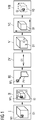
- Figure 1 shows a block diagram of the process flow of a preferred method according to the invention.
- Figures 2 to 4 see Figures 2 to 4 .
- a number of objects 01 is provided in the environment, each comprising a marking element M1.
- the marking element M1 here could comprise an individual identification code that is indicated with a pattern on the marking element M1.
- the marking element M1 is a visual marker with a defined dimension and is applied at a surface of the object 01.
- step II a visual image-dataset ID of the object O1 is recorded with a camera 2 such that an image of the marking element M1 i is visible in the image-dataset ID.
- a parameter value PV based on the marking element M1 here the size of the image of the marking element M1 i in the image-dataset ID, is determined. Also a beacon could be used as marking element M1 and its signal intensity could be measured as parameter value PV.
- the size of the image of the marking element M1 i depends on the distance between the object 01 and the camera 2.
- step IV the relative distance D1 between the object 01 and the camera 2 is calculated from the parameter value PV (the size of the image of the marking element M1 i ), e.g. by using the known size of the marking element M1 and the known distance of the image from the optic of the camera 2 or the focus of the optics of the camera 2.
- PV the size of the image of the marking element M1 i
- step V the dimensions a, b, c of the object 01 are calculated from at least a part of the image of the object 01 in the image-dataset ID and the calculated distance D1.
- step VI the relative position of the object 01 in the environment as seen by the camera 2 is calculated based on the calculated distance D1 and the position of the object 01 in the image-dataset ID.
- a virtual object VO is created within a virtual reality environment having the same distance and dimensions as the object 01 in the virtual reality environment, preferably providing an identification mark GI connected with the virtual object VO, particularly preferably wherein the identification mark GI of the virtual object VO corresponds to the pattern, i.e. the identification code, of the marking element M1 of the object O1.
- the identification mark GI of the virtual object VO corresponds to the pattern, i.e. the identification code, of the marking element M1 of the object O1.
- it is a virtual marker.
- a label could be applied to the virtual object VO.
- Figure 2 shows a preferred scheme for an acquisition of an image-dataset ID as well as a preferred device 1 and a preferred system 6.
- the preferred device 1 comprises:
- the device also comprises a virtual reality display 5, here a head-up display 5, to display virtual objects VO (see e.g. figure 1 ) for a user in a virtual reality environment.
- a virtual reality display here a head-up display 5
- virtual objects VO see e.g. figure 1
- the shown device 1 together with the virtual reality display 5 could serve as control unit according to the invention.
- the preferred system 6 comprises the device 1 and the number of objects O1, O2 each comprising a marking element M1, M2.
- Two objects O1, O2 are recorded with the camera 2.
- the method as described above and shown in figure 1 is applied, wherein the distances D1, D2 between the objects O1, O2 and the camera 2 are calculated as well as the dimensions a, b, c of the objects O1, O2 and the positions of the objects O1, O2 relative to a coordinate system X, Y, Z.
- This coordinate system X, Y, Z could be originate anywhere in the environment.
- the relative distance D3 between the objects O1, O2 is derived from these calculations.
- any point of an object O1, O2 can serve as origin for the calculation of a distance D1, D2.
- the marking elements M1, M2 are important features of the objects O1, O2, it is preferred to define them as origin.
- Figure 3 shows another preferred scheme for an acquisition of an image-dataset ID.
- a high dynamic range image (HDR-image) with a series of focal points FP is recorded as image-dataset ID.
- the distance D1 and dimensions a, b, c of the object 01 can be calculated.
- the ratio of the sizes of the marking element M1 and the image of the marking element M1 i is used to calculate the dimensions a, b, c.
- the calculation is preferably achieved by slicing the area around a marking element M1 and/or the object 01, wherein the slices comprise images recorded with different focal points FP, wherein in each slice a higher amount of sharp spots are detected as plane/line.
- the depth of the recorded light field and/or the sharpness of the image is observed in the slices and image-dimensions of the image of the object 01 are calculated based on the depth of the recorded light field and/or the sharpness of the image.
- the distance D1 and/or dimension a, b, c of the object 01 is determined based on the image dimensions, preferably the dimensions of the marking element M1 and the known values of a focusing optics of the camera 2.
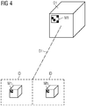
- Figure 4 shows another preferred scheme for an acquisition of an image-dataset ID.
- a stereo-image is recorded, wherein a relative distance D1 between an object 01 and the camera 2 is calculated using triangulation based on the (stereo-)image of the marking element M1 i .
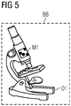
- Figure 5 shows an object 01 with a bounding box BB.
- This object 01 here a microscope
- This bounding box BB could be used.
- the bounding box BB could be designed by identifying the object 01 in the image-dataset ID and building a bounding box BB around the identified object.
Description
- The invention pertains to a method and a device to determine the dimensions and distance of a number of objects in an environment, especially for implementing data of the objects in a virtual reality, a system, especially for medical use and a control unit suitable for virtual reality.
- Virtual reality (VR), i.e. the creation of an artificial environment for a user, has become more and more interesting for various technical and medical fields. One important goal is to integrate real objects and persons in a virtual environment, e.g. as virtual objects or as avatars. To achieve this, a virtual reality unit should have the ability to scan the environment, track objects or persons in this environment and create virtual objects or avatars in the virtual reality at a position equivalent to the reality. Often, a VR-unit has to be trained to achieve this goal.
- Up to now, VR trainings are achieved by tracking humans and afterwards mapping in virtual reality. To map also (static) objects in the environment or objects a person interacts with, these objects have to be put in their appropriate positions in VR in a time-consuming way until now. Until today there is no acceptable solution of tracking the objects (e.g. a C-arm of an X-ray system) in a way humans can be tracked to avoid the time-consuming construction of a virtual training. Especially, there is no technical solution without optical tracking using IR-signals implemented until now.
- Since for the motion of a user in virtual reality there always is the risk in running into real objects that are not correctly or not at all shown in VR and since for the ability to use real objects while being in VR, it is a major disadvantage that there only exist tracking suits for recording the movement of a human body but no suitable tracking of objects.
EP2546806 discloses augmented Reality for furniture replacement /virtual handling by attaching a marker on each piece of furniture and detection the camera pose in view of the marker using the acquired image of the marker. - H. KATO et al: "Virtual object manipulation on a table-top AR environment" discloses robust marker tracking in the presence of multiple markers for augmented reality purposes.
- H. KATO et al: "Marker tracking and HMD calibration for a video-based augmented reality conferencing system" discloses marker tracking and HMD calibration for a video-based augmented reality conferencing system
- It is the object of the present invention to improve the known devices and methods to facilitate an improvement in determining the dimensions and distance of a number of objects in an environment, especially for implementing real objects in virtual reality.
- This object is achieved by a method according to claim 1, a device according to claim 10, a system according to claim 12 and a control unit according to claim 13.
- A method according to the invention to determine the dimensions and distance of a number of objects in an environment comprises the following steps:
- Providing a number of objects, each comprising a marking element, in the environment. The marking element should be located in or on the object. A suitable marking element is e.g. a beacon, especially a Bluetooth-Low-Energy (BLE) beacon or a visible QR-code.
- Recording a visual image-dataset of at least one of the number of objects with a camera. Such image dataset could comprise a (single) picture, a set of pictures or a set of image data in a picture (e.g. a HDR image with various focal points). The "image-dataset" could also be designated as "image", "photo" or "picture", however, it should be clear that it could comprise the data of one, two or more images taken by the camera (e.g. a stereo-image or an HDR-Image). In the easiest case one single photography could be used.
- Determining a parameter value of the marking element from the image-dataset or from the measurement of an additional sensor at the location of the camera, wherein the parameter value is a value depending from the distance between the object and the camera. This parameter value is important for the invention. The requirement that the parameter value is a value depending from the distance between the object and the camera means that the distance between the object and the camera could be directly or indirectly can be derived from this value. For example, the intensity of a signal from a beacon could be used. Also, the image of a marking element in the image-data could be used as value, since the size of the marking element is known and the distance can be derived from this size and a formula of common projection optics.
- Calculating the relative distance between the object and the camera based on this parameter value. This relative distance could e.g. be easily calculated from the intensity of a signal from a beacon arranged in or on this object (since the absolute signal power is known or can easily be measured). From the attenuation of the signal over the distance the distance can be derived. Another example using an image of a marking element is described above.
- Calculating dimensions of the object from at least a part of the image of the object in the image-dataset and the calculated distance. This could also be achieved by using the image of a marking element. The dimensions of the image of the object could e.g. be determined in units of the size of the marking element and then be transferred to the real dimensions via a reversion of formulae of common projection optics. Another example is the use of above mentioned signal of the beacon and the dimensions of the object in the image data. To calculate the dimensions of the object in real world, also formulae of projection optics can be used. However, there could be the case that the shape of the object is complex (e.g. a X-ray-system). Then a marking element that is arranged on the surface of the object and being seen in the image-data is advantageous, since by the deformation of the image of the marking element (e.g. a rectangular marking element projected as a parallelogram in the image data) could be used to calculate a rotational orientation of the object in the environment relative to the camera.
- A device according to the invention to record a number of objects in an environment, wherein a number of objects is provided with a marking element, comprises the following components:
- A camera designed to record a visual image-dataset of at least one of the objects.
- A determination device designed to determine a parameter value from an image of a marking element in the image-dataset or from another source, wherein the parameter value is dependent from the distance between the object and the camera.
- A calculation unit designed to calculate the relative distance between the object and the camera based on this parameter value, as well as calculate dimensions of the object from at least a part of the image of the object in the image-dataset and the calculated distance.
- A system according to the invention suitable to record a number of objects in an environment, especially for medical use, comprises a device according to the invention and a number of objects, preferably medical objects, particularly preferably medical devices. Each of these objects comprises a marking element.
- A control unit according to the invention for a virtual reality system comprises a device according to the invention.
- Some units or modules of the device or the control unit mentioned above can be completely or partially realized as software modules running on a processor of a device or a control unit. A realization largely in the form of software modules can have the advantage that applications already installed on an existing system can be updated, with relatively little effort, to install and run these units of the present application. The object of the invention is also achieved by a computer program product with a computer program that is directly loadable into the memory of a device or a control unit of an MRI-system, and which comprises program units to perform the steps of the inventive method when the program is executed by the control unit or the device. In addition to the computer program, such a computer program product can also comprise further parts such as documentation and/or additional components, also hardware components such as a hardware key (dongle etc.) to facilitate access to the software.
- A computer readable medium such as a memory stick, a hard-disk or other transportable or permanently-installed carrier can serve to transport and/or to store the executable parts of the computer program product so that these can be read from a processor unit of a control unit or a device. A processor unit can comprise one or more microprocessors or their equivalents.
- Particularly advantageous embodiments and features of the invention are given by the dependent claims, as revealed in the following description. Features of different claim categories may be combined as appropriate to give further embodiments not described herein.
- According to a preferred method, a number of objects comprise a marking element actively sending electromagnetic signals with a distance-dependent signal shape. The signal could be a Bluetooth signal or another electromagnetic signal with a distance dependent intensity. The dependence of intensity and distance can easily be measured or calculated. The signal of the marking element could be measured with a senor of the camera or an additional sensor arranged at the location of the camera.
- It is preferred that the marking element sends or shows an individual identification code. This is independent of the type of marking element. This could be achieved by printing an individual code or pattern on the marking element or in that the marking element sends a signal with an individual encoding. The information of the marking element, especially its identification, are preferably stored together with the image-dataset.
- It is particularly preferred that the signal element is a Bluetooth marker, preferably a Bluetooth low energy tag, also called "BLE-Beacon".
- According to a preferred method, the relative position of an object in relation to the camera is calculated based on the distance of the object and the position of the object in the image-dataset, wherein preferably also the dimensions of the object are considered in this calculation. Preferably, a coordinate system is assigned to an object at the end of this calculation and/or a relative distance between two objects is derived from this calculation.
- According to a preferred method, the relative position of the camera in relation to an object is determined via Bluetooth low energy indoor navigation, the principle of Simultaneous Localization and Mapping ("SLAM") or inertial sensors. These sensors could e.g. be found in a smartphone, tablet computer or notebook, wherein the onboard camera of such device is preferably used as camera to take the image-dataset.
- According to a preferred method, a marking element is a visual marker with a defined dimension and is applied at a surface of an object. There it could be seen by the camera. The determined parameter value needed to calculate the distance is preferably the image of the marker. Then the relative distance between the object and the camera and/or the dimensions of the object are preferably calculated from the image of the marker and the known values of a focusing optics of the camera. It should be noted that the marking elements have to appear on a picture of the image-dataset and their size has to be known. To get a good result in praxis, several marking elements should be applied at different surfaces so that there can be seen at least one marking element from any position in the environment.
- According to a preferred method, in the course of recording a visual image-dataset, a stereo-image is recorded, wherein a relative distance between an object and the camera is calculated using triangulation based on the stereo-image of the marking element. This allows a fast and accurate determination of the distance and also the orientation of the object in the environment.
- According to a preferred method, in the course of recording a visual image-dataset, a high dynamic range image and/or an image with different focus points is recorded. This provides image data with a good contrast and a good luminosity.
- Preferably, the distance and/or dimension of an object is determined by
- slicing the area around a marking element and/or an object, wherein the slices comprise images recorded with different focal points, wherein in each slice a higher amount of sharp spots are detected as plane/line, and
- observing the depth of the recorded light field and/or the sharpness of the image in the slices and calculating image-dimensions of the image of the object based on the depth of the recorded light field and/or the sharpness of the image,
- determining the distance and/or dimension of an object based on the image dimensions, preferably the dimensions of the marking element and the known values of a focusing optics of the camera.
- The slices are the pictures (of the HDR-dataset) with different focal points. On every picture, there is one sharp plane of the environment and other areas are diffuse. Since the focus "moves" in the image-dataset, there is a series of pictures with different sharp areas. The focal point of the picture, where one surface or edge of an object is pictured sharp is taken as distance, wherein dimensions of the object can be calculated from the set of pictures where other surfaces or edges of the object are sharp. By moving through the images while shifting the focal point, one can scan "along the object". It is also possible to first determine a set of dimensions of the image of the object, then determine the distance to a defined point of the object (e.g. a surface or the center of mass) and then calculate the real dimensions of the object by scaling the set of dimensions depending on the distance.
- It should generally be noted that the projection scale S of the camera is well known. Any calculations of sizes in the reality A based on the projection optic from the image size B can be made based on the formula A = 1/S · B. However, there are more sophisticated formulae concerning all kinds of distortions or imaging errors.
- According to a preferred method, an object is identified in the image-dataset. Then there could preferably be built a bounding box around the identified object. The size of a marking element is related to the (contour lines of the) bounding box around the object to determine the dimensions of the object. This is preferably achieved by calculating how many times the marker fits in the area of the bounding box. This bounding box makes it easier to arrange an object in a virtual reality environment.
- According to a preferred method, there is performed the additional step of creating a virtual object within a virtual reality having the same distance and dimensions as the object. It is preferred to provide an identification mark connected with the virtual object, particularly preferably wherein the identification mark of the virtual object corresponds to an identification code of a marking element of the object. For example, when the marking element of the (real) object sends or shows a certain code, this code could be used as an identification mark for the respective virtual object.
- A preferred device comprises a virtual reality display, wherein the device comprises a virtual reality calculating unit designed to create a virtual object having the same distance and dimensions as an object of the environment and display virtual objects on the virtual reality display. It is preferred that the housing of the virtual reality display comprises the camera, since then it is guaranteed that the view of the camera corresponds to the viewing direction of the virtual reality display. The same is valid for the distance to an object.
- Other objects and features of the present invention will become apparent from the following detailed descriptions considered in conjunction with the accompanying drawings. It is to be understood, however, that the drawings are designed solely for the purposes of illustration and not as a definition of the limits of the invention.
-
Figure 1 shows a block diagram of the process flow of a preferred method according to the invention. -
Figure 2 shows a preferred scheme for an acquisition of an image-dataset as well as a preferred device and a preferred system. -
Figure 3 shows another preferred scheme for an acquisition of an image-dataset. -
Figure 4 shows another preferred scheme for an acquisition of an image-dataset. -
Figure 5 shows an object with a bounding box. - In the diagrams, like numbers refer to like objects throughout. Objects in the diagrams are not necessarily drawn to scale.
-
Figure 1 shows a block diagram of the process flow of a preferred method according to the invention. For a possible setup and reference signs, seeFigures 2 to 4 . - In step I, a number of
objects 01 is provided in the environment, each comprising a marking element M1. The marking element M1 here could comprise an individual identification code that is indicated with a pattern on the marking element M1. Here, the marking element M1 is a visual marker with a defined dimension and is applied at a surface of theobject 01. - In step II, a visual image-dataset ID of the object O1 is recorded with a
camera 2 such that an image of the marking element M1i is visible in the image-dataset ID. - In step III, a parameter value PV based on the marking element M1, here the size of the image of the marking element M1i in the image-dataset ID, is determined. Also a beacon could be used as marking element M1 and its signal intensity could be measured as parameter value PV. The size of the image of the marking element M1i depends on the distance between the
object 01 and thecamera 2. - In step IV, the relative distance D1 between the
object 01 and thecamera 2 is calculated from the parameter value PV (the size of the image of the marking element M1i), e.g. by using the known size of the marking element M1 and the known distance of the image from the optic of thecamera 2 or the focus of the optics of thecamera 2. - In step V, the dimensions a, b, c of the
object 01 are calculated from at least a part of the image of theobject 01 in the image-dataset ID and the calculated distance D1. - In step VI, the relative position of the
object 01 in the environment as seen by thecamera 2 is calculated based on the calculated distance D1 and the position of theobject 01 in the image-dataset ID. - In step VII, a virtual object VO is created within a virtual reality environment having the same distance and dimensions as the
object 01 in the virtual reality environment, preferably providing an identification mark GI connected with the virtual object VO, particularly preferably wherein the identification mark GI of the virtual object VO corresponds to the pattern, i.e. the identification code, of the marking element M1 of the object O1. Here it is a virtual marker. Also a label could be applied to the virtual object VO. -
Figure 2 shows a preferred scheme for an acquisition of an image-dataset ID as well as a preferred device 1 and apreferred system 6. - The preferred device 1 comprises:
- a
camera 2 designed to record a visual image-dataset ID of the objects O1, O2 positioned in the environment, - a
determination device 3 designed to determine a parameter value PV from images of the marking elements M1i, M2i of the image-dataset ID. The device could alternatively or additionally comprise a sensor e.g. for measuring the intensity of a Bluetooth signal. - a
calculation unit 4 designed to calculate the relative distances D1, D2 between the objects O1, O2 and thecamera 2 based on this parameter value PV, as well as calculate dimensions a, b, c of the objects O1, O2 from at least a part of the image of the objects O1, O2 in the image-dataset ID and the calculated distances D1, D2. - The device also comprises a
virtual reality display 5, here a head-updisplay 5, to display virtual objects VO (see e.g.figure 1 ) for a user in a virtual reality environment. - The shown device 1 together with the
virtual reality display 5 could serve as control unit according to the invention. - The
preferred system 6 comprises the device 1 and the number of objects O1, O2 each comprising a marking element M1, M2. - Two objects O1, O2 are recorded with the
camera 2. The method as described above and shown infigure 1 is applied, wherein the distances D1, D2 between the objects O1, O2 and thecamera 2 are calculated as well as the dimensions a, b, c of the objects O1, O2 and the positions of the objects O1, O2 relative to a coordinate system X, Y, Z. This coordinate system X, Y, Z could be originate anywhere in the environment. In addition, the relative distance D3 between the objects O1, O2 is derived from these calculations. - Concerning the distances D1, D2, they here are shown as the distances D1, D2 between
camera 2 and the marking elements M1, M2. This is not necessary. In general, any point of an object O1, O2 can serve as origin for the calculation of a distance D1, D2. However, since the marking elements M1, M2 are important features of the objects O1, O2, it is preferred to define them as origin. -
Figure 3 shows another preferred scheme for an acquisition of an image-dataset ID. Here a high dynamic range image (HDR-image) with a series of focal points FP is recorded as image-dataset ID. By identifying sharp areas of theobject 01 in the different images of the image-dataset ID (at different focal points FP), the distance D1 and dimensions a, b, c of theobject 01 can be calculated. Here, also the ratio of the sizes of the marking element M1 and the image of the marking element M1i (see dashed ellipse) is used to calculate the dimensions a, b, c. - The calculation is preferably achieved by slicing the area around a marking element M1 and/or the
object 01, wherein the slices comprise images recorded with different focal points FP, wherein in each slice a higher amount of sharp spots are detected as plane/line. After that the depth of the recorded light field and/or the sharpness of the image is observed in the slices and image-dimensions of the image of theobject 01 are calculated based on the depth of the recorded light field and/or the sharpness of the image. Last, the distance D1 and/or dimension a, b, c of theobject 01 is determined based on the image dimensions, preferably the dimensions of the marking element M1 and the known values of a focusing optics of thecamera 2. -
Figure 4 shows another preferred scheme for an acquisition of an image-dataset ID. Here in the course of recording a visual image-dataset ID, a stereo-image is recorded, wherein a relative distance D1 between anobject 01 and thecamera 2 is calculated using triangulation based on the (stereo-)image of the marking element M1i. -
Figure 5 shows anobject 01 with a bounding box BB. This object 01 (here a microscope) has a very complex shape. To simplify the arrangement of the object in a virtual reality environment, this bounding box BB could be used. The bounding box BB could be designed by identifying theobject 01 in the image-dataset ID and building a bounding box BB around the identified object. - The invention is defined by the appended claims. For the sake of clarity, it is to be understood that the use of "a" or "an" throughout this application does not exclude a plurality, and "comprising" does not exclude other steps or elements. The mention of a "unit" or a "module" does not preclude the use of more than one unit or module.
Claims (15)
- A computer-implemented method to determine the dimensions (a, b, c) and distance (D1, D2) of a number of objects (O1, O2) in an environment comprising the steps:- providing a number of objects (O1, O2), each comprising a marking element (M1, M2), in the environment,- recording a visual image-dataset (ID) of at least one of the number of objects (O1, O2) with a camera (2), wherein in the course of recording a visual image-dataset (ID), an image with different focus points is recorded,- determining a parameter value (V) from the image of a marking element (M1i, M2i) in the image-dataset (ID), wherein the parameter value (PV) is a value depending on the distance (D1, D2) of an object of the number of objects (O1, O2) each comprising a marking element (M1, M2) to the camera (2),- calculating the relative distance between the object (O1, O2) and the camera (2) based on this parameter value (PV),- calculating dimensions (a, b, c) of the object (O1, O2) from at least a part of the image of the object (O1, O2) in the image-dataset (ID) and the calculated distance (D1, D2),wherein the dimensions (a, b, c) of the object (O1, O2) is determined by- slicing the area around a marking element (M1, M2) wherein the slices comprise images recorded with different focus points (FP), and- observing the depth of the recorded light field and/or the sharpness of the image in the slices and calculating image-dimensions of the image of the object (O1, O2) based on the depth of the recorded light field and/or the sharpness of the image,- determining the dimensions (a, b, c) of the object (O1, O2) based on the image- dimensions of the image of the object (O1, O2), the dimensions of the marking element (M1, M2) and the known values of a focusing optic of the camera (2).
- The method as claimed in claim 1, wherein a relative position of an object (O1, O2) in relation to the camera is calculated based on the distance (D1, D2) of the object and the position of the object in the image-dataset (ID), wherein preferably also the dimensions (a, b, c) of the object (O1, O2) are considered in this calculation.
- The method as claimed in one of the preceding claims, wherein a number of objects (O1, O2) comprise a marking element (M1, M2), preferably a Bluetooth low energy tag, actively sending electromagnetic signals with a distance-dependent signal shape,
wherein the marking element (M1, M2) preferably sends and/or shows an individual identification code,
wherein the signal of the marking element is measured with a sensor of the camera or an additional sensor arranged at the location of the camera. - The method as claimed in one of the preceding claims, wherein the relative position of the camera (2) in relation to an object (O1, O2) is determined via Bluetooth low energy indoor navigation, Simultaneous Localization and Mapping or inertial sensors.
- The method as claimed in one of the preceding claims, wherein a marking element (M1, M2) is a visual marker with a defined dimension and is applied at a surface of an object (O1, O2), wherein the determined parameter value (V) is the image of the marking element (M1, M2)
- The method as claimed in one of the preceding claims, wherein in the course of recording a visual image-dataset (ID), a stereo-image is recorded, wherein a relative distance (D1, D2) between an object (O1, O2) and the camera (2) is calculated using triangulation based on the stereo-image of the marking element (M1i, M2i) .
- The method as claimed in one of the preceding claims, wherein in the course of recording a visual image-dataset (ID), an image with different focus points is recorded, wherein the distance (D1, D2) is determined by- slicing the area around a marking element (M1, M2) wherein the slices comprise images recorded with different focal points (FP), wherein in each slice a higher amount of sharp spots are detected as plane/line, and- observing the depth of the recorded light field and/or the sharpness of the image in the slices and calculating image-dimensions of the image of the object (O1, O2) based on the depth of the recorded light field and/or the sharpness of the image,- determining the distance (D1, D2) of an object (O1, O2) based on the image- dimensions of the image of the object (O1, O2) the dimensions of the marking element (M1, M2) and the known values of a focusing optic of the camera (2).
- The method as claimed in one of the preceding claims, wherein an object (O1, O2) is identified in the image-dataset (ID), wherein preferably a bounding box (BB) is built around the identified object (O1, O2) and the size of a marking element (M1, M2) is related to the bounding box (BB) around the object (O1, O2) to determine the dimensions (a, b, c) of the object (O1, O2), preferably by calculating how many times the marking element (M1, M2) fits in the area of the bounding box (BB).
- The method as claimed in one of the preceding claims, comprising the additional step:- creating a virtual object within a virtual reality having the same distance and dimensions as the object (O1, O2), preferably providing an identification mark connected with the virtual object, particularly preferably wherein the identification mark of the virtual object corresponds to an identification code of a marking element (M1, M2) of the object (O1, O2).
- A device to record a number of objects (O1, O2) in an environment, wherein a number of objects (O1, O2) is provided with a marking element (M1, M2), comprising:- a camera (2) designed to record a visual image-dataset (ID) in form of an image with different focus points of at least one of the objects (O1, O2),- a determination device (3) designed to determine a parameter value from an image of a marking element (M1i, M2i) in the image-dataset (ID), wherein the parameter value (V) is dependent on the distance (D1, D2) of an object of the number of objects (O1, 02) each comprising a marking element (M1, M2) to the camera (2),- a calculation unit (4) designed towherein the dimensions (a,b,c) of the object (O1, O2) are determined bya) calculate the relative distance (D1, D2) between the object (O1, O2) and the camera (2) based on this parameter value (V),b) calculate dimensions (a, b, c) of the object (O1, O2) from at least a part of the image of the object (O1, O2) in the image-dataset (ID) and the calculated distance (D1, D2),- slicing the area around a marking element (M1, M2), wherein the slices comprise images recorded with different focal points (FP), and- observing the depth of the recorded light field and/or the sharpness of the image in the slices and calculating image-dimensions of the image of the object (O1, O2) based on the depth of the recorded light field and/or the sharpness of the image,- determining the dimensions (a, b, c) of an object (O1, O2) based on the image-dimensions of the image of the object (01,02), the dimensions of the
marking element (M1, M2) and the known values of a focusing optic of the camera (2). - The device (1) as claimed in claim 10, comprising a virtual reality display (5), wherein the device (1) comprises a virtual reality calculating unit designed to create a virtual object having the same distance and dimensions as an object (O1, O2) of the environment and display virtual objects on the virtual reality display (5).
- A system, to record a number of objects (O1, O2) in an environment, comprising a device (1) according to claim 10 or 11 and a number of objects (O1, O2), preferably medical objects, particularly preferably medical devices, each comprising a marking element (M1, M2).
- A control unit for a virtual reality system comprising a device (1) according to claim 10 or 11.
- A computer program product comprising instructions which, when the program is executed by a computer, cause the computer to carry out the steps of the method of any of claims 1 to 9.
- A computer-readable medium comprising instructions which, when executed by a computer, cause the computer to carry out the steps of the method of any of the claims 1 to 9.
Priority Applications (3)
| Application Number | Priority Date | Filing Date | Title |
|---|---|---|---|
| EP19161318.1A EP3706076B1 (en) | 2019-03-07 | 2019-03-07 | Method and device to determine the dimensions and distance of a number of objects in an environment |
| US16/807,456 US11043037B2 (en) | 2019-03-07 | 2020-03-03 | Method and device to determine the dimensions and distance of a number of objects in an environment |
| CN202010150530.XA CN111667526B (en) | 2019-03-07 | 2020-03-06 | Method and apparatus for determining the size and distance of a plurality of objects in an environment |
Applications Claiming Priority (1)
| Application Number | Priority Date | Filing Date | Title |
|---|---|---|---|
| EP19161318.1A EP3706076B1 (en) | 2019-03-07 | 2019-03-07 | Method and device to determine the dimensions and distance of a number of objects in an environment |
Publications (2)
| Publication Number | Publication Date |
|---|---|
| EP3706076A1 EP3706076A1 (en) | 2020-09-09 |
| EP3706076B1 true EP3706076B1 (en) | 2021-02-24 |
Family
ID=65763264
Family Applications (1)
| Application Number | Title | Priority Date | Filing Date |
|---|---|---|---|
| EP19161318.1A Active EP3706076B1 (en) | 2019-03-07 | 2019-03-07 | Method and device to determine the dimensions and distance of a number of objects in an environment |
Country Status (3)
| Country | Link |
|---|---|
| US (1) | US11043037B2 (en) |
| EP (1) | EP3706076B1 (en) |
| CN (1) | CN111667526B (en) |
Families Citing this family (5)
| Publication number | Priority date | Publication date | Assignee | Title |
|---|---|---|---|---|
| USD959477S1 (en) | 2019-12-20 | 2022-08-02 | Sap Se | Display system or portion thereof with a virtual three-dimensional animated graphical user interface |
| USD959476S1 (en) | 2019-12-20 | 2022-08-02 | Sap Se | Display system or portion thereof with a virtual three-dimensional animated graphical user interface |
| USD959447S1 (en) | 2019-12-20 | 2022-08-02 | Sap Se | Display system or portion thereof with a virtual three-dimensional animated graphical user interface |
| US11205296B2 (en) * | 2019-12-20 | 2021-12-21 | Sap Se | 3D data exploration using interactive cuboids |
| DE102020129792B4 (en) * | 2020-11-11 | 2023-03-09 | Volume Graphics Gmbh | Computer-implemented method for determining a value of a geometric parameter |
Family Cites Families (29)
| Publication number | Priority date | Publication date | Assignee | Title |
|---|---|---|---|---|
| US6396397B1 (en) * | 1993-02-26 | 2002-05-28 | Donnelly Corporation | Vehicle imaging system with stereo imaging |
| WO2004025541A1 (en) * | 2002-09-16 | 2004-03-25 | Imaging Therapeutics, Inc. | Imaging markers in musculoskeletal disease |
| CN100538741C (en) * | 2004-08-31 | 2009-09-09 | 美国西门子医疗解决公司 | The candidate of lung nodule detection produces |
| US7863763B2 (en) * | 2005-11-22 | 2011-01-04 | Asml Netherlands B.V. | Binary sinusoidal sub-wavelength gratings as alignment marks |
| JP4424364B2 (en) * | 2007-03-19 | 2010-03-03 | ソニー株式会社 | Image processing apparatus and image processing method |
| DE102007033486B4 (en) * | 2007-07-18 | 2010-06-17 | Metaio Gmbh | Method and system for mixing a virtual data model with an image generated by a camera or a presentation device |
| US20100321640A1 (en) * | 2009-06-22 | 2010-12-23 | Industrial Technology Research Institute | Projection display chip |
| CN102753954A (en) * | 2009-12-22 | 2012-10-24 | 纽约大学 | Sorting colloidal particles into multiple channels with optical forces: prismatic optical fractionation |
| CN102192727A (en) * | 2010-03-19 | 2011-09-21 | 阿尔卡特朗讯 | Mobile handheld device and method |
| US9959595B2 (en) * | 2010-09-21 | 2018-05-01 | Mobileye Vision Technologies Ltd. | Dense structure from motion |
| EP2546806B1 (en) * | 2011-07-11 | 2019-05-08 | Deutsche Telekom AG | Image based rendering for ar - enabling user generation of 3d content |
| US9025252B2 (en) * | 2011-08-30 | 2015-05-05 | Microsoft Technology Licensing, Llc | Adjustment of a mixed reality display for inter-pupillary distance alignment |
| CA2851590A1 (en) * | 2011-10-10 | 2013-04-18 | Tractus Corporation | Method, apparatus and system for complete examination of tissue with hand-held imaging devices |
| EP2608153A1 (en) * | 2011-12-21 | 2013-06-26 | Harman Becker Automotive Systems GmbH | Method and system for playing an augmented reality game in a motor vehicle |
| EP2842077A4 (en) * | 2012-04-26 | 2016-04-20 | Univ Columbia | Systems, methods, and media for providing interactive refocusing in images |
| US9182812B2 (en) * | 2013-01-08 | 2015-11-10 | Ayotle | Virtual sensor systems and methods |
| CN104077746B (en) * | 2013-03-29 | 2017-03-01 | 富士通株式会社 | Gray level image processing method and its device |
| CN103557859B (en) * | 2013-10-10 | 2015-12-23 | 北京智谷睿拓技术服务有限公司 | Image acquisition localization method and image acquisition positioning system |
| JP6264834B2 (en) * | 2013-10-24 | 2018-01-24 | 富士通株式会社 | Guide method, information processing apparatus, and guide program |
| CN103591943A (en) * | 2013-11-17 | 2014-02-19 | 罗建刚 | Method for line laying operation guided through image |
| US20160125638A1 (en) * | 2014-11-04 | 2016-05-05 | Dassault Systemes | Automated Texturing Mapping and Animation from Images |
| CN104572967B (en) * | 2014-12-30 | 2018-01-19 | 北京奇虎科技有限公司 | A kind of method and apparatus in page graphing |
| CN106327449B (en) * | 2016-09-12 | 2019-05-03 | 厦门美图之家科技有限公司 | A kind of image repair method, device and calculate equipment |
| US10366263B2 (en) * | 2016-12-30 | 2019-07-30 | Accenture Global Solutions Limited | Object detection for video camera self-calibration |
| CA3009798A1 (en) * | 2017-07-12 | 2019-01-12 | General Electric Company | Graphic overlay for measuring dimensions of features using a video inspection device |
| DE102017215074A1 (en) * | 2017-08-29 | 2019-02-28 | Siemens Healthcare Gmbh | Method and selection unit for selecting a virtual object or a picture parameter value |
| US20200279389A1 (en) * | 2017-11-17 | 2020-09-03 | C 3 Limited | Object measurement system |
| CN108765338A (en) * | 2018-05-28 | 2018-11-06 | 西华大学 | Spatial target images restored method based on convolution own coding convolutional neural networks |
| US11010919B2 (en) * | 2018-09-20 | 2021-05-18 | Ford Global Technologies, Llc | Object locator with fiducial marker |
-
2019
- 2019-03-07 EP EP19161318.1A patent/EP3706076B1/en active Active
-
2020
- 2020-03-03 US US16/807,456 patent/US11043037B2/en active Active
- 2020-03-06 CN CN202010150530.XA patent/CN111667526B/en active Active
Non-Patent Citations (1)
| Title |
|---|
| None * |
Also Published As
| Publication number | Publication date |
|---|---|
| CN111667526B (en) | 2023-07-28 |
| US20200286291A1 (en) | 2020-09-10 |
| CN111667526A (en) | 2020-09-15 |
| EP3706076A1 (en) | 2020-09-09 |
| US11043037B2 (en) | 2021-06-22 |
Similar Documents
| Publication | Publication Date | Title |
|---|---|---|
| EP3706076B1 (en) | Method and device to determine the dimensions and distance of a number of objects in an environment | |
| US9448758B2 (en) | Projecting airplane location specific maintenance history using optical reference points | |
| US20170132806A1 (en) | System and method for augmented reality and virtual reality applications | |
| TWI496108B (en) | AR image processing apparatus and method | |
| US8086026B2 (en) | Method and system for the determination of object positions in a volume | |
| JP5055516B2 (en) | System and method for displaying device maintenance and operation instructions using augmented reality | |
| CN106664776B (en) | Stadium lighting sighting system and method | |
| CN109949899A (en) | Image three-dimensional measurement method, electronic equipment, storage medium and program product | |
| CN104685541A (en) | Method and an apparatus for determining a gaze point on a three-dimensional object | |
| CN101702233B (en) | Three-dimension locating method based on three-point collineation marker in video frame | |
| RU2720076C1 (en) | Method of angular and spatial coordinates estimation of objects in reference points in optical-electronic positioning system | |
| CN110009682A (en) | A kind of object recognition and detection method based on monocular vision | |
| CN104254755A (en) | Optical measurement system, method and scaleplate therefor | |
| Sobel et al. | Camera calibration for tracked vehicles augmented reality applications | |
| US11259000B2 (en) | Spatiotemporal calibration of RGB-D and displacement sensors | |
| CN109934873A (en) | Mark image acquiring method, device and equipment | |
| Aalerud et al. | Automatic calibration of an industrial RGB-D camera network using retroreflective fiducial markers | |
| CN107014293A (en) | A kind of photogrammetric survey method of camera scanning imaging | |
| CN113884081B (en) | Method and equipment for measuring three-dimensional coordinates of positioning point | |
| Thabit et al. | Evaluation of marker tracking using mono and stereo vision in Microsoft HoloLens for surgical navigation | |
| CN208314856U (en) | A kind of system for the detection of monocular airborne target | |
| Singh et al. | A report on registration problems in Augmented Reality | |
| Xu et al. | Multi-target indoor tracking and recognition system with infrared markers for virtual reality | |
| Rezzoug et al. | A Vision Based Optical Measurement Technique With Augmented Reality Concepts | |
| Madritsch et al. | Camera based beacon tracking: accuracy and applications |
Legal Events
| Date | Code | Title | Description |
|---|---|---|---|
| STAA | Information on the status of an ep patent application or granted ep patent |
Free format text: STATUS: EXAMINATION IS IN PROGRESS |
|
| PUAI | Public reference made under article 153(3) epc to a published international application that has entered the european phase |
Free format text: ORIGINAL CODE: 0009012 |
|
| 17P | Request for examination filed |
Effective date: 20191219 |
|
| AK | Designated contracting states |
Kind code of ref document: A1 Designated state(s): AL AT BE BG CH CY CZ DE DK EE ES FI FR GB GR HR HU IE IS IT LI LT LU LV MC MK MT NL NO PL PT RO RS SE SI SK SM TR |
|
| AX | Request for extension of the european patent |
Extension state: BA ME |
|
| GRAP | Despatch of communication of intention to grant a patent |
Free format text: ORIGINAL CODE: EPIDOSNIGR1 |
|
| STAA | Information on the status of an ep patent application or granted ep patent |
Free format text: STATUS: GRANT OF PATENT IS INTENDED |
|
| INTG | Intention to grant announced |
Effective date: 20200924 |
|
| GRAS | Grant fee paid |
Free format text: ORIGINAL CODE: EPIDOSNIGR3 |
|
| GRAA | (expected) grant |
Free format text: ORIGINAL CODE: 0009210 |
|
| STAA | Information on the status of an ep patent application or granted ep patent |
Free format text: STATUS: THE PATENT HAS BEEN GRANTED |
|
| AK | Designated contracting states |
Kind code of ref document: B1 Designated state(s): AL AT BE BG CH CY CZ DE DK EE ES FI FR GB GR HR HU IE IS IT LI LT LU LV MC MK MT NL NO PL PT RO RS SE SI SK SM TR |
|
| REG | Reference to a national code |
Ref country code: CH Ref legal event code: EP |
|
| REG | Reference to a national code |
Ref country code: DE Ref legal event code: R096 Ref document number: 602019002649 Country of ref document: DE |
|
| REG | Reference to a national code |
Ref country code: AT Ref legal event code: REF Ref document number: 1365441 Country of ref document: AT Kind code of ref document: T Effective date: 20210315 |
|
| REG | Reference to a national code |
Ref country code: IE Ref legal event code: FG4D |
|
| REG | Reference to a national code |
Ref country code: LT Ref legal event code: MG9D |
|
| REG | Reference to a national code |
Ref country code: NL Ref legal event code: MP Effective date: 20210224 |
|
| PG25 | Lapsed in a contracting state [announced via postgrant information from national office to epo] |
Ref country code: BG Free format text: LAPSE BECAUSE OF FAILURE TO SUBMIT A TRANSLATION OF THE DESCRIPTION OR TO PAY THE FEE WITHIN THE PRESCRIBED TIME-LIMIT Effective date: 20210524 Ref country code: GR Free format text: LAPSE BECAUSE OF FAILURE TO SUBMIT A TRANSLATION OF THE DESCRIPTION OR TO PAY THE FEE WITHIN THE PRESCRIBED TIME-LIMIT Effective date: 20210525 Ref country code: FI Free format text: LAPSE BECAUSE OF FAILURE TO SUBMIT A TRANSLATION OF THE DESCRIPTION OR TO PAY THE FEE WITHIN THE PRESCRIBED TIME-LIMIT Effective date: 20210224 Ref country code: HR Free format text: LAPSE BECAUSE OF FAILURE TO SUBMIT A TRANSLATION OF THE DESCRIPTION OR TO PAY THE FEE WITHIN THE PRESCRIBED TIME-LIMIT Effective date: 20210224 Ref country code: LT Free format text: LAPSE BECAUSE OF FAILURE TO SUBMIT A TRANSLATION OF THE DESCRIPTION OR TO PAY THE FEE WITHIN THE PRESCRIBED TIME-LIMIT Effective date: 20210224 Ref country code: PT Free format text: LAPSE BECAUSE OF FAILURE TO SUBMIT A TRANSLATION OF THE DESCRIPTION OR TO PAY THE FEE WITHIN THE PRESCRIBED TIME-LIMIT Effective date: 20210624 Ref country code: NO Free format text: LAPSE BECAUSE OF FAILURE TO SUBMIT A TRANSLATION OF THE DESCRIPTION OR TO PAY THE FEE WITHIN THE PRESCRIBED TIME-LIMIT Effective date: 20210524 |
|
| REG | Reference to a national code |
Ref country code: AT Ref legal event code: MK05 Ref document number: 1365441 Country of ref document: AT Kind code of ref document: T Effective date: 20210224 |
|
| PG25 | Lapsed in a contracting state [announced via postgrant information from national office to epo] |
Ref country code: SE Free format text: LAPSE BECAUSE OF FAILURE TO SUBMIT A TRANSLATION OF THE DESCRIPTION OR TO PAY THE FEE WITHIN THE PRESCRIBED TIME-LIMIT Effective date: 20210224 Ref country code: PL Free format text: LAPSE BECAUSE OF FAILURE TO SUBMIT A TRANSLATION OF THE DESCRIPTION OR TO PAY THE FEE WITHIN THE PRESCRIBED TIME-LIMIT Effective date: 20210224 Ref country code: NL Free format text: LAPSE BECAUSE OF FAILURE TO SUBMIT A TRANSLATION OF THE DESCRIPTION OR TO PAY THE FEE WITHIN THE PRESCRIBED TIME-LIMIT Effective date: 20210224 Ref country code: LV Free format text: LAPSE BECAUSE OF FAILURE TO SUBMIT A TRANSLATION OF THE DESCRIPTION OR TO PAY THE FEE WITHIN THE PRESCRIBED TIME-LIMIT Effective date: 20210224 Ref country code: RS Free format text: LAPSE BECAUSE OF FAILURE TO SUBMIT A TRANSLATION OF THE DESCRIPTION OR TO PAY THE FEE WITHIN THE PRESCRIBED TIME-LIMIT Effective date: 20210224 |
|
| PG25 | Lapsed in a contracting state [announced via postgrant information from national office to epo] |
Ref country code: IS Free format text: LAPSE BECAUSE OF FAILURE TO SUBMIT A TRANSLATION OF THE DESCRIPTION OR TO PAY THE FEE WITHIN THE PRESCRIBED TIME-LIMIT Effective date: 20210624 |
|
| PG25 | Lapsed in a contracting state [announced via postgrant information from national office to epo] |
Ref country code: SM Free format text: LAPSE BECAUSE OF FAILURE TO SUBMIT A TRANSLATION OF THE DESCRIPTION OR TO PAY THE FEE WITHIN THE PRESCRIBED TIME-LIMIT Effective date: 20210224 Ref country code: AT Free format text: LAPSE BECAUSE OF FAILURE TO SUBMIT A TRANSLATION OF THE DESCRIPTION OR TO PAY THE FEE WITHIN THE PRESCRIBED TIME-LIMIT Effective date: 20210224 Ref country code: EE Free format text: LAPSE BECAUSE OF FAILURE TO SUBMIT A TRANSLATION OF THE DESCRIPTION OR TO PAY THE FEE WITHIN THE PRESCRIBED TIME-LIMIT Effective date: 20210224 Ref country code: CZ Free format text: LAPSE BECAUSE OF FAILURE TO SUBMIT A TRANSLATION OF THE DESCRIPTION OR TO PAY THE FEE WITHIN THE PRESCRIBED TIME-LIMIT Effective date: 20210224 |
|
| REG | Reference to a national code |
Ref country code: DE Ref legal event code: R097 Ref document number: 602019002649 Country of ref document: DE |
|
| PG25 | Lapsed in a contracting state [announced via postgrant information from national office to epo] |
Ref country code: DK Free format text: LAPSE BECAUSE OF FAILURE TO SUBMIT A TRANSLATION OF THE DESCRIPTION OR TO PAY THE FEE WITHIN THE PRESCRIBED TIME-LIMIT Effective date: 20210224 Ref country code: SK Free format text: LAPSE BECAUSE OF FAILURE TO SUBMIT A TRANSLATION OF THE DESCRIPTION OR TO PAY THE FEE WITHIN THE PRESCRIBED TIME-LIMIT Effective date: 20210224 Ref country code: RO Free format text: LAPSE BECAUSE OF FAILURE TO SUBMIT A TRANSLATION OF THE DESCRIPTION OR TO PAY THE FEE WITHIN THE PRESCRIBED TIME-LIMIT Effective date: 20210224 Ref country code: MC Free format text: LAPSE BECAUSE OF FAILURE TO SUBMIT A TRANSLATION OF THE DESCRIPTION OR TO PAY THE FEE WITHIN THE PRESCRIBED TIME-LIMIT Effective date: 20210224 |
|
| REG | Reference to a national code |
Ref country code: BE Ref legal event code: MM Effective date: 20210331 |
|
| PLBE | No opposition filed within time limit |
Free format text: ORIGINAL CODE: 0009261 |
|
| STAA | Information on the status of an ep patent application or granted ep patent |
Free format text: STATUS: NO OPPOSITION FILED WITHIN TIME LIMIT |
|
| PG25 | Lapsed in a contracting state [announced via postgrant information from national office to epo] |
Ref country code: LU Free format text: LAPSE BECAUSE OF NON-PAYMENT OF DUE FEES Effective date: 20210307 Ref country code: IE Free format text: LAPSE BECAUSE OF NON-PAYMENT OF DUE FEES Effective date: 20210307 Ref country code: AL Free format text: LAPSE BECAUSE OF FAILURE TO SUBMIT A TRANSLATION OF THE DESCRIPTION OR TO PAY THE FEE WITHIN THE PRESCRIBED TIME-LIMIT Effective date: 20210224 Ref country code: ES Free format text: LAPSE BECAUSE OF FAILURE TO SUBMIT A TRANSLATION OF THE DESCRIPTION OR TO PAY THE FEE WITHIN THE PRESCRIBED TIME-LIMIT Effective date: 20210224 |
|
| 26N | No opposition filed |
Effective date: 20211125 |
|
| PG25 | Lapsed in a contracting state [announced via postgrant information from national office to epo] |
Ref country code: IT Free format text: LAPSE BECAUSE OF FAILURE TO SUBMIT A TRANSLATION OF THE DESCRIPTION OR TO PAY THE FEE WITHIN THE PRESCRIBED TIME-LIMIT Effective date: 20210224 |
|
| PG25 | Lapsed in a contracting state [announced via postgrant information from national office to epo] |
Ref country code: IS Free format text: LAPSE BECAUSE OF FAILURE TO SUBMIT A TRANSLATION OF THE DESCRIPTION OR TO PAY THE FEE WITHIN THE PRESCRIBED TIME-LIMIT Effective date: 20210624 |
|
| PG25 | Lapsed in a contracting state [announced via postgrant information from national office to epo] |
Ref country code: BE Free format text: LAPSE BECAUSE OF NON-PAYMENT OF DUE FEES Effective date: 20210331 |
|
| REG | Reference to a national code |
Ref country code: CH Ref legal event code: PL |
|
| PG25 | Lapsed in a contracting state [announced via postgrant information from national office to epo] |
Ref country code: LI Free format text: LAPSE BECAUSE OF NON-PAYMENT OF DUE FEES Effective date: 20220331 Ref country code: CH Free format text: LAPSE BECAUSE OF NON-PAYMENT OF DUE FEES Effective date: 20220331 |
|
| PGFP | Annual fee paid to national office [announced via postgrant information from national office to epo] |
Ref country code: FR Payment date: 20230317 Year of fee payment: 5 |
|
| PGFP | Annual fee paid to national office [announced via postgrant information from national office to epo] |
Ref country code: DE Payment date: 20220620 Year of fee payment: 5 |
|
| PG25 | Lapsed in a contracting state [announced via postgrant information from national office to epo] |
Ref country code: CY Free format text: LAPSE BECAUSE OF FAILURE TO SUBMIT A TRANSLATION OF THE DESCRIPTION OR TO PAY THE FEE WITHIN THE PRESCRIBED TIME-LIMIT Effective date: 20210224 |
|
| PG25 | Lapsed in a contracting state [announced via postgrant information from national office to epo] |
Ref country code: SI Free format text: LAPSE BECAUSE OF FAILURE TO SUBMIT A TRANSLATION OF THE DESCRIPTION OR TO PAY THE FEE WITHIN THE PRESCRIBED TIME-LIMIT Effective date: 20210224 Ref country code: HU Free format text: LAPSE BECAUSE OF FAILURE TO SUBMIT A TRANSLATION OF THE DESCRIPTION OR TO PAY THE FEE WITHIN THE PRESCRIBED TIME-LIMIT; INVALID AB INITIO Effective date: 20190307 |
|
| PGFP | Annual fee paid to national office [announced via postgrant information from national office to epo] |
Ref country code: GB Payment date: 20230403 Year of fee payment: 5 |
|
| REG | Reference to a national code |
Ref country code: DE Ref legal event code: R081 Ref document number: 602019002649 Country of ref document: DE Owner name: SIEMENS HEALTHINEERS AG, DE Free format text: FORMER OWNER: SIEMENS HEALTHCARE GMBH, MUENCHEN, DE |