EP2176602B1 - Device for heating a fluid through solar energy - Google Patents
Device for heating a fluid through solar energy Download PDFInfo
- Publication number
- EP2176602B1 EP2176602B1 EP08789522A EP08789522A EP2176602B1 EP 2176602 B1 EP2176602 B1 EP 2176602B1 EP 08789522 A EP08789522 A EP 08789522A EP 08789522 A EP08789522 A EP 08789522A EP 2176602 B1 EP2176602 B1 EP 2176602B1
- Authority
- EP
- European Patent Office
- Prior art keywords
- cylinder
- plane
- mirror
- solar energy
- roller bearing
- Prior art date
- Legal status (The legal status is an assumption and is not a legal conclusion. Google has not performed a legal analysis and makes no representation as to the accuracy of the status listed.)
- Active
Links
- 238000010438 heat treatment Methods 0.000 title claims abstract description 20
- 239000012530 fluid Substances 0.000 title claims abstract description 16
- 239000012141 concentrate Substances 0.000 claims abstract description 3
- 230000033001 locomotion Effects 0.000 claims description 9
- 230000001174 ascending effect Effects 0.000 claims description 3
- 238000005452 bending Methods 0.000 claims description 3
- XLYOFNOQVPJJNP-UHFFFAOYSA-N water Substances O XLYOFNOQVPJJNP-UHFFFAOYSA-N 0.000 description 4
- 239000000872 buffer Substances 0.000 description 3
- 239000000463 material Substances 0.000 description 3
- 230000005855 radiation Effects 0.000 description 3
- 230000005611 electricity Effects 0.000 description 2
- 238000009434 installation Methods 0.000 description 2
- 239000007788 liquid Substances 0.000 description 2
- 238000010079 rubber tapping Methods 0.000 description 2
- UFHFLCQGNIYNRP-UHFFFAOYSA-N Hydrogen Chemical compound [H][H] UFHFLCQGNIYNRP-UHFFFAOYSA-N 0.000 description 1
- 239000003570 air Substances 0.000 description 1
- WYTGDNHDOZPMIW-RCBQFDQVSA-N alstonine Natural products C1=CC2=C3C=CC=CC3=NC2=C2N1C[C@H]1[C@H](C)OC=C(C(=O)OC)[C@H]1C2 WYTGDNHDOZPMIW-RCBQFDQVSA-N 0.000 description 1
- 238000003490 calendering Methods 0.000 description 1
- 239000003795 chemical substances by application Substances 0.000 description 1
- 239000011248 coating agent Substances 0.000 description 1
- 238000000576 coating method Methods 0.000 description 1
- 238000001816 cooling Methods 0.000 description 1
- 230000007423 decrease Effects 0.000 description 1
- 230000000694 effects Effects 0.000 description 1
- 230000002708 enhancing effect Effects 0.000 description 1
- 230000007613 environmental effect Effects 0.000 description 1
- 230000002349 favourable effect Effects 0.000 description 1
- 239000001307 helium Substances 0.000 description 1
- 229910052734 helium Inorganic materials 0.000 description 1
- SWQJXJOGLNCZEY-UHFFFAOYSA-N helium atom Chemical compound [He] SWQJXJOGLNCZEY-UHFFFAOYSA-N 0.000 description 1
- 239000001257 hydrogen Substances 0.000 description 1
- 229910052739 hydrogen Inorganic materials 0.000 description 1
- 239000011810 insulating material Substances 0.000 description 1
- 239000012212 insulator Substances 0.000 description 1
- 230000010354 integration Effects 0.000 description 1
- 230000000670 limiting effect Effects 0.000 description 1
- 230000009347 mechanical transmission Effects 0.000 description 1
- 230000002093 peripheral effect Effects 0.000 description 1
- 238000002310 reflectometry Methods 0.000 description 1
- 238000004513 sizing Methods 0.000 description 1
- 229910001220 stainless steel Inorganic materials 0.000 description 1
- 239000010935 stainless steel Substances 0.000 description 1
- 230000009182 swimming Effects 0.000 description 1
Images


Classifications
-
- F—MECHANICAL ENGINEERING; LIGHTING; HEATING; WEAPONS; BLASTING
- F24—HEATING; RANGES; VENTILATING
- F24S—SOLAR HEAT COLLECTORS; SOLAR HEAT SYSTEMS
- F24S23/00—Arrangements for concentrating solar-rays for solar heat collectors
- F24S23/70—Arrangements for concentrating solar-rays for solar heat collectors with reflectors
- F24S23/74—Arrangements for concentrating solar-rays for solar heat collectors with reflectors with trough-shaped or cylindro-parabolic reflective surfaces
-
- F—MECHANICAL ENGINEERING; LIGHTING; HEATING; WEAPONS; BLASTING
- F24—HEATING; RANGES; VENTILATING
- F24S—SOLAR HEAT COLLECTORS; SOLAR HEAT SYSTEMS
- F24S30/00—Arrangements for moving or orienting solar heat collector modules
- F24S30/40—Arrangements for moving or orienting solar heat collector modules for rotary movement
- F24S30/42—Arrangements for moving or orienting solar heat collector modules for rotary movement with only one rotation axis
- F24S30/428—Arrangements for moving or orienting solar heat collector modules for rotary movement with only one rotation axis with inclined axis
-
- F—MECHANICAL ENGINEERING; LIGHTING; HEATING; WEAPONS; BLASTING
- F24—HEATING; RANGES; VENTILATING
- F24S—SOLAR HEAT COLLECTORS; SOLAR HEAT SYSTEMS
- F24S60/00—Arrangements for storing heat collected by solar heat collectors
- F24S60/30—Arrangements for storing heat collected by solar heat collectors storing heat in liquids
-
- Y—GENERAL TAGGING OF NEW TECHNOLOGICAL DEVELOPMENTS; GENERAL TAGGING OF CROSS-SECTIONAL TECHNOLOGIES SPANNING OVER SEVERAL SECTIONS OF THE IPC; TECHNICAL SUBJECTS COVERED BY FORMER USPC CROSS-REFERENCE ART COLLECTIONS [XRACs] AND DIGESTS
- Y02—TECHNOLOGIES OR APPLICATIONS FOR MITIGATION OR ADAPTATION AGAINST CLIMATE CHANGE
- Y02E—REDUCTION OF GREENHOUSE GAS [GHG] EMISSIONS, RELATED TO ENERGY GENERATION, TRANSMISSION OR DISTRIBUTION
- Y02E10/00—Energy generation through renewable energy sources
- Y02E10/40—Solar thermal energy, e.g. solar towers
- Y02E10/47—Mountings or tracking
Abstract
Description
- The present invention relates to a device for heating a fluid through solar energy.
- Currently, both for attention to environmental protection and for reasons of economy or else, the general interest turned to alternative energy sources is known to be in continuous expansion. Industry, for years, has placed on the market several products that exploit solar energy for various purposes. Skipping particular uses generally reserved to industry, the more typical one is applied to the heating sector. In this area, the market proposes several types of solar panels, which though present the common feature to be fixed. It is clear that their performance reaches a maximum peak when the sun strikes them perpendicularly but decreases then more or less drastically while getting away from this ideal condition. Even perfectly directing the solar panels on midday sun during the summer, they would result too inclined for the winter sun. It can easily be imagined that in order to exploit them more homogeneously throughout the year it is therefore necessary to install the solar panels with a compromise inclination. Then, if we consider that the more you get away from central hours of the day, more the energy is reflected from the socket that protects the tapping elements, it is easy to understand how reduced the actual percentage of useful energy is. And it still has to be considered that if the few hours in which the efficiency reaches culmination coincide with a momentary cloudiness of the sky, the final result obtained is really disappointing,
- Up to now the only solution to this problem has been to oversize the area of the panels, However, often there is not available space eneugh, therefore it is frequently necessary to give up the installation.
-
US 4 644 933 illustrates a solar collector which combines a magnifying lens with separate reflectors to increase solar collection. The collector also tracks celestial movement so as to constantly maintain maximum solar exposure. -
US 4 351 319 discloses an apparatus for maintaining a radiation sensitive portion thereof in alignment with a distant source of radiation during relative movement between the situs of the apparatus and the source, wherein movement from alignment causes a differential in energy output in spaced apart elements of the radiation sensitive portion which is transformed into mechanical energy to return the portion to alignment. -
US 4 291 677 illustrates a solar energy collector comprising a parabola shaped mirror formed by a plurality of flexible reflective film strips stretched over a plurality of supports being arranged to position the film in a parabola shape. The mirror is pivotally secured to a support assembly whereby the mirror can be maintained at the same relative position to the sun. Positioning of the mirror is controlled by an energy rays tracking device. The supports are adjustable such that light and infrared energy rays striking the film between the supports are reflected to the focus of the mirror around which a collector assembly is located. -
US 4 307 711 discloses a sun tracking solar energy collector system comprising a plurality of light focusing elements disposed side by side in the form of a surface array, providing a linear array of foci, and a metallic heat exchanger tube having externally a high absorptivity, low reflectivity coating containing a working fluid such as water, air, hydrogen or helium, to which a substantial portion of the energy in the focused light is imparted. - The aim of the present invention is to overcome the cited drawbacks by devising a device for heating a fluid through solar energy suitable to rapture, in perfect autonomy, all solar energy that striker it.
- Within this aim, it is a further aim of the present invention to provide with a device for heating a fluid through solar energy with reduced dimensions.
- Another aim of the present invention is to provide with a device for heating a fluid through solar energy of simple, constructive and functional conception, equipped with a certainly reliable functioning, of versatile use, as well as of relatively economical costs.
- The cited aims are reached, according to the claimed invention, by a device for heating a fluid through solar energy according to claim 1.
- Description details of the invention will be further evident in the illustrations of preferred embodiments of the device for heating a fluid through solar energy according to the invention, illustrated in the guideline drawings attached, wherein:
-
Fig. 1 illustrates an axonometric view of a device for heating a fluid through solar energy according to the claimed invention; -
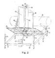
Fig. 2 illustrates an axonometric view of the device from a different angle; -
Fig. 3 illustrates an exploded side view of a detail of the device. - With reference to such
figures, 1 indicates the frame of the device for heating a fluid through solar energy. The frame 1 is equipped withfeet 2 necessary for the installation on a horizontal plane or for the anchorage to brackets prearranged in case of inclined planets. - On the base frame are arranged the ringbolts 3, useful to fix possible tie rods, the buffers 4, the
control unit 5 seated inside a tight box and underneath it the fixed part of theactuator 6. For a good functioning, the base frame must be mounted horizontal and with the greater axis preferably in direction north-south. On an inner crossbeam of the frame some hinges 7 are mounted, to which is fixed one side of the inclinable plane 8, which can vary its inclination through theactuator 6. The excursion limits are imposed by electrical limit switch, inside theactuator 6, and mechanic stops, consisting for example of buffers 4 and pins 9 (only one illustrated). In ascending movement, where the effort is greater, theactuator 6 is helped by the weight of the exchanger 10 (or otherwise by any inert mass), placed rocking on the opposite side of the mobile plain and, for the first degrees, also by the thrust of the buffers. At the centre of the plane and perpendicular to it acylinder 12 is fixed, thanks to a robust socket 11. From the lower end of thecylinder 12 come out supply andoutput pipes 13, while on the upper end arelief valve 14 is coaxially mounted, well secured. Suitably, atemperature sensor 15 is provided, placed either on the outside of the cylinder, as illustrated, or inside it. According to the materials used and to the type of use, it may also be necessary, inside the cylinder, to install a corrosion-proofing cathode (not illustrated). The supply and outlet pipes of the cylinder are connected with twohoses 16 directly to the mouths 17 hot-cold fixed to the inner crossbeam (this is the configuration of the direct heating of the fluid or where an exchanger is used different from the one equipped). If however the use the equipped exchanger, with interposed pump and possible expansion tank, is desired, the hoses will have to be connected to this element. Above the inclinable plane, outside the socket, the circular plane 18 is mounted. Thanks to a series of bearings (or other revolving members), some of which mounted on a specific ring 19, the circular plane is maintained rested on the plane, centered as regards the axis of the cylinder but free to turn through anengine 20. The space between the circular plane and the plane below hosts and protects the mechanical transmission members, which can be inspected only through the manhole 21. The circular plane rotates to follow the apparent motion of the sun from morning to evening, limited in extreme positions by electrical and mechanical limit switch. On the crown and perpendicular to it, are mounted atransparent pane 22, two rigid heat-insulatingmaterial edges 23, a reflective pane 24 (for example, of mirrored stainless steel) calendered with parabolic bending whose fulcrum coincides with the axis of the cylinder. Immediately above the cylinder there is a cover 25, also of rigid material and heat-insulating, which houses, at the centre, in anappropriate seat 26, a roller bearing 27 whose inner part is inserted into the body of therelief valve 14. The bearing is mechanically connected but electrically isolated with appropriate insulator both towards the valve and towards the cover. This bearing serves multiple functions: - (a) to support a part of the weight of the cylinder (and its contents), especially when, in the central hours of the day, it is in an almost horizontal position, allowing the rotation between valve and cover.
- (b) thanks to the fact that can slide axially, it allows the cylinder to stretch due to the effect of thermal expansions and allows convenient dismantling of the cover when necessary.
- (c) to ensure the electrical continuity between the fixed part (the cylinder) and that mobile (the impeller), connection whose utility will be dealt later on. It can easily be imagined how the cylinder, and with it the fluid in it, heats up, both for direct solar energy that frontally strikes it, and for the energy reflected by the mirror that concentrates it at the rear. The room consisting of a portion of the circular plane, the mirror, the transparent pane, the sides and the cover, in addition to maintaining the parties enclosed inside clean and protected by external agents, prevents the cylinder from heating subtractions, otherwise inevitable. Also the convex face of the mirror (the one turned outward) has to be properly coated to limit the heat loss. A series of
brackets 28 anchored to the circular crown is meant to hold the mirror and the rear part of the cover. Above the lid is situated, fitted with two brackets, a smallphotovoltaic panel 29, meant to provide all electricity required by the control and movement members. Furthermore, above the lid aposition sensor 30 is mounted, which generates the piece of information required to follow the sun. In the inner upper part of thelid 31 that protects the relief valve and the roller bearing, there is acircuit 32 that elaborates the pieces of information and mixes them with the direct current produced by the panel. The roller bearing transfers all this to awire 33 that runs parallel to the cylinder, comes out of a hole underneath the socket, and with other wires finally comes to the electronic control unit. This, equipped with a battery, serves mainly to the following functions: - 1) making the cylinder and with it the photovoltaic panel remain perpendicular to sunbeams or anyway to the lighter area of the sky;
- 2) replacing the impeller at rest toward east after dusk;
- (3) intervening in case of too high or too low temperatures (if required);
- (4) controlling possible peripheral devices.
- By varying the diameter ratio of the cylinder (which may be a tank, a serpentine or any other enhancing element) and the area of the overall tapping, it is possible to shift from the field of low temperatures (below 100 °C) to medium ones (between 100 and 250 °C).
- In the field of low temperatures applications of the object may be many, such as:
- (a) direct heating of water for swimming pools, sanitary fittings and showers in seaside resorts, camping sites, houses in places not served by electricity and the like;
- (b) with supplied heat exchanger or other (with intermediate liquid), heating for sanitary hot water (household and similar);
- (c) with kettle (with intermediate liquid) heating sanitary hot water and integration to the room traditional heating;
- In the field of medium temperatures:
- (a) the heating of forced-air-circulation rooms;
- (b) cooling of rooms.
- The claimed device reaches the aim to capture, in perfect autonomy, the whole solar energy that hits it. This is obtained in particular thanks to the fact that there are electromechanical members that maintain it always oriented in the more favorable direction. This gives it a definitely higher efficiency compared to the one of the traditional fixed collectors, with equal surface committed.
- It has to be pointed out that the plane that tilts 8 holds the circular plane 18, which rotates and not vice versa as it happens, for example, in tracking photovoltaic panels. This allows a considerable constructive simplification at expense of a little appreciable reduction of the coverage of the apparent trajectory of the sun (limitedly to some winter months and only in the central hours of the day).
- It also has to be noted that, if we exclude a slight variation in the bending radius of the two flexible tubes, when the plane 8 tilts, between mobile and fixed parts there are neither tubes nor electrical cables that wind. This makes the mechanism very reliable.
- It must also be noted that the
heat exchanger 10 is placed rocking on the opposite side of the mobile plane (8), in order to reduce the effort of the actuator in the first ascending part, the more difficult, and therefore also its sizing in the project. - Furthermore, it has to be notes that the
roller bearing 27 is suitable to assure the electrical continuity between the fixed part and the mobile one. This function may also be carried out by means of cables, which though inevitably twist themselves and therefore wear quickly, either by means of sliding contacts, which wear out with time and which however unnecessarily increase the complexity of the mechanism. - In case reasons of space or of aesthetics would require so, nothing precludes the possibility to vary with a large margin, the relationship width-height of the claimed device. It is possible to transform the device in a small central energy, for example by increasing the area of the photovoltaic panels and/or integrating them with a small wind generator, thus providing the user also with precious electric power.
- The materials adopted for the actual realization of the invention, as well as their shapes and sizes, can be various, depending on the requirements.
- Where technical features mentioned in any claim are followed by reference signs, those reference signs have been included for the sole purpose of increasing the intelligibility of the claims and accordingly such reference signs do not have any limiting effect on the scope of each element identified by way of example by such reference signs.
Claims (10)
- Device for heating a fluid through solar energy, comprising a cylinder (12) suitable to contain the fluid to be heated; a parabolic mirror (24) having the focal point coinciding with the axis of said cylinder (12) so as to concentrate solar energy that radiates on the cylinder (12) itself; a circular plane (18) carrying said mirror (24) and suitable to be operated in rotation by an engine (20),
said device being characterized in that it comprises:a plane (8) that can be tilted on command by actuators (6), carrying the unit formed by said cylinder (12), mirror (24) and circular plane (18) in order to optimize the angle of elevation as to the horizontal plane;a photovoltaic panel (29) suited to provide the electric power needed by the control and movement members, said photovoltaic panel being mounted on the revolving part, in order to remain always oriented in the position of maximum performance;a heat exchanger (10) placed rocking on the opposite site of said mobile plane (8) such that the actuator (6) is helped by the weight of said heat exchanger (10) in ascending movement. a room consisting of a portion of said plane (18), of said mirror (24), of a transparent pane (22), of two sides and of a cover (25), which, in addition to maintaining the parts enclosed inside clean and protected by external agents, prevents the cylinder from heating subtractions, wherein said cylinder (12) is enclosed inside said room. - Device according to claim 1, characterized in that, when the plane (8) tilts, between the mobile and fixed parts there are neither pipes nor electrical cables that twist themselves, except for a slight variation in the bending radius of two flexible tubes.
- Device according to claim 1, characterized in that only the parabolic mirror (24) rotates to maintain its axis in the direction of the sun, while said cylinder (12) tilts together with the mirror but does not rotate.
- Device according to claim 1, characterized in that it comprises a roller bearing (27) that, in addition to interface the fixed part (14) with the mobile one (25), partially holds the weight of said cylinder (12).
- Device according to claim 4, characterized in that the roller bearing (27) easily allows the disassembly of the lid (25).
- Device according to claim 4, characterized in that the roller bearing (27) allows the cylinder (12) to stretch due to thermal expansions.
- Device according to claim 4, characterized in that the roller bearing (27) is suitable to ensure the electrical continuity between the fixed part and the mobile part.
- Device according to claim 1, characterized in that it comprises a relief valve (14), which is the upper mechanical pin of the cylinder (12), being mounted on its axis.
- Device according to claim 8, characterized in that on the body of said relief valve (14) is placed the inner part of the roller bearing (27).
- Device according to claim 1, characterized in that it comprises a series of bearings, or other revolving means, which constrain the circular plane (18) to the plane (8) that can be tilted, allowing it only with a circular motion.
Applications Claiming Priority (2)
| Application Number | Priority Date | Filing Date | Title |
|---|---|---|---|
| IT000006U ITFO20070006U1 (en) | 2007-08-03 | 2007-08-03 | MECHANISM TO HEAT A FLUID BY MEANS OF SOLAR ENERGY, WITH TRACKING |
| PCT/IB2008/053095 WO2009019643A2 (en) | 2007-08-03 | 2008-08-01 | Device for heating a fluid through solar energy |
Publications (2)
| Publication Number | Publication Date |
|---|---|
| EP2176602A2 EP2176602A2 (en) | 2010-04-21 |
| EP2176602B1 true EP2176602B1 (en) | 2011-10-19 |
Family
ID=40166162
Family Applications (1)
| Application Number | Title | Priority Date | Filing Date |
|---|---|---|---|
| EP08789522A Active EP2176602B1 (en) | 2007-08-03 | 2008-08-01 | Device for heating a fluid through solar energy |
Country Status (5)
| Country | Link |
|---|---|
| EP (1) | EP2176602B1 (en) |
| AT (1) | ATE529709T1 (en) |
| ES (1) | ES2373506T3 (en) |
| IT (1) | ITFO20070006U1 (en) |
| WO (1) | WO2009019643A2 (en) |
Families Citing this family (1)
| Publication number | Priority date | Publication date | Assignee | Title |
|---|---|---|---|---|
| WO2010013270A1 (en) * | 2008-07-31 | 2010-02-04 | Green Earth S.R.L. | Rotating linear focused thermal energy solar concentrator with vertically inclinable axis |
Citations (2)
| Publication number | Priority date | Publication date | Assignee | Title |
|---|---|---|---|---|
| US4291677A (en) * | 1977-12-27 | 1981-09-29 | Monk Robert J | Solar energy collector |
| US4307711A (en) * | 1980-02-25 | 1981-12-29 | Doundoulakis George J | Sun tracking solar energy collector system |
Family Cites Families (7)
| Publication number | Priority date | Publication date | Assignee | Title |
|---|---|---|---|---|
| US2247830A (en) * | 1938-07-07 | 1941-07-01 | Charles G Abbot | Solar heater |
| FR2257067A1 (en) * | 1974-01-04 | 1975-08-01 | Pages Michel | Sun's energy collector device - has paraboloid mirror focussing rays on liquid flow heat exchanger |
| US4351319A (en) * | 1979-08-17 | 1982-09-28 | Robbins Jr Roland W | Radiant energy tracker |
| AU549379B2 (en) * | 1979-09-07 | 1986-01-23 | Magule Pty. Ltd. | Solar energy collector |
| GB2147408A (en) * | 1983-10-04 | 1985-05-09 | Dimos Maglaras | Solar water heater |
| US4587952A (en) * | 1985-05-10 | 1986-05-13 | Richardson John L | Passive solar water heater |
| US4644933A (en) * | 1985-10-28 | 1987-02-24 | Gregory Samuel T | Solar system |
-
2007
- 2007-08-03 IT IT000006U patent/ITFO20070006U1/en unknown
-
2008
- 2008-08-01 WO PCT/IB2008/053095 patent/WO2009019643A2/en active Application Filing
- 2008-08-01 ES ES08789522T patent/ES2373506T3/en active Active
- 2008-08-01 AT AT08789522T patent/ATE529709T1/en active
- 2008-08-01 EP EP08789522A patent/EP2176602B1/en active Active
Patent Citations (2)
| Publication number | Priority date | Publication date | Assignee | Title |
|---|---|---|---|---|
| US4291677A (en) * | 1977-12-27 | 1981-09-29 | Monk Robert J | Solar energy collector |
| US4307711A (en) * | 1980-02-25 | 1981-12-29 | Doundoulakis George J | Sun tracking solar energy collector system |
Also Published As
| Publication number | Publication date |
|---|---|
| ATE529709T1 (en) | 2011-11-15 |
| ES2373506T3 (en) | 2012-02-06 |
| EP2176602A2 (en) | 2010-04-21 |
| WO2009019643A4 (en) | 2009-06-04 |
| ITFO20070006U1 (en) | 2007-11-02 |
| WO2009019643A3 (en) | 2009-04-02 |
| WO2009019643A2 (en) | 2009-02-12 |
Similar Documents
| Publication | Publication Date | Title |
|---|---|---|
| US4088120A (en) | Solar concentrator-collector | |
| US4284839A (en) | Internal refractor focusing solar energy collector apparatus and method | |
| CA2590165C (en) | Solar energy collection system | |
| US20100206302A1 (en) | Rotational Trough Reflector Array For Solar-Electricity Generation | |
| CN102216697A (en) | Configuration and tracking of 2-d modular heliostat | |
| TW201109601A (en) | Apparatus and system to lower cost per watt with concentrated linear solar panel | |
| KR20110048548A (en) | Solar energy conversion | |
| US20120174966A1 (en) | Concentrating tracking solar energy collector | |
| AU2005331708B2 (en) | Thermoelectric solar plant | |
| US20080308152A1 (en) | Solar collector with angled cooling fins | |
| EP0065562A1 (en) | Variable entropy solar energy harvester | |
| US20100043777A1 (en) | Solar collector system | |
| WO2018083506A1 (en) | Concentrating solar system of 3 suns for the simultaneous production of electrical, cooling and thermal energy for buildings | |
| CN102405381A (en) | Stationary parabolic solar power system and related methods for collecting solar energy | |
| Gunther et al. | Solar dish technology | |
| Kalogirou | Recent patents in solar energy collectors and applications | |
| US20110240097A1 (en) | Concentrating solar energy collector system with photovoltaic cells | |
| US8030605B2 (en) | Method and device for the utilization of solar energy | |
| US20120186575A1 (en) | Solar Collector | |
| US20140261392A1 (en) | Solar Collector | |
| US20140366930A1 (en) | Hybrid solar energy recovery system | |
| EP2176602B1 (en) | Device for heating a fluid through solar energy | |
| JP2005106432A (en) | Solar light collection and heat collection device | |
| US20130327400A1 (en) | Direct solar-radiation collection and concentration element and panel | |
| US20130180517A1 (en) | Solar Energy Collecting Assembly |
Legal Events
| Date | Code | Title | Description |
|---|---|---|---|
| PUAI | Public reference made under article 153(3) epc to a published international application that has entered the european phase |
Free format text: ORIGINAL CODE: 0009012 |
|
| 17P | Request for examination filed |
Effective date: 20100211 |
|
| AK | Designated contracting states |
Kind code of ref document: A2 Designated state(s): AT BE BG CH CY CZ DE DK EE ES FI FR GB GR HR HU IE IS IT LI LT LU LV MC MT NL NO PL PT RO SE SI SK TR |
|
| AX | Request for extension of the european patent |
Extension state: AL BA MK RS |
|
| 17Q | First examination report despatched |
Effective date: 20100514 |
|
| R17C | First examination report despatched (corrected) |
Effective date: 20100521 |
|
| GRAP | Despatch of communication of intention to grant a patent |
Free format text: ORIGINAL CODE: EPIDOSNIGR1 |
|
| GRAS | Grant fee paid |
Free format text: ORIGINAL CODE: EPIDOSNIGR3 |
|
| GRAA | (expected) grant |
Free format text: ORIGINAL CODE: 0009210 |
|
| DAX | Request for extension of the european patent (deleted) | ||
| AK | Designated contracting states |
Kind code of ref document: B1 Designated state(s): AT BE BG CH CY CZ DE DK EE ES FI FR GB GR HR HU IE IS IT LI LT LU LV MC MT NL NO PL PT RO SE SI SK TR |
|
| REG | Reference to a national code |
Ref country code: GB Ref legal event code: FG4D |
|
| REG | Reference to a national code |
Ref country code: CH Ref legal event code: EP |
|
| REG | Reference to a national code |
Ref country code: IE Ref legal event code: FG4D |
|
| REG | Reference to a national code |
Ref country code: DE Ref legal event code: R096 Ref document number: 602008010640 Country of ref document: DE Effective date: 20111215 |
|
| REG | Reference to a national code |
Ref country code: ES Ref legal event code: FG2A Ref document number: 2373506 Country of ref document: ES Kind code of ref document: T3 Effective date: 20120206 |
|
| REG | Reference to a national code |
Ref country code: NL Ref legal event code: VDEP Effective date: 20111019 |
|
| LTIE | Lt: invalidation of european patent or patent extension |
Effective date: 20111019 |
|
| PG25 | Lapsed in a contracting state [announced via postgrant information from national office to epo] |
Ref country code: LT Free format text: LAPSE BECAUSE OF FAILURE TO SUBMIT A TRANSLATION OF THE DESCRIPTION OR TO PAY THE FEE WITHIN THE PRESCRIBED TIME-LIMIT Effective date: 20111019 Ref country code: BE Free format text: LAPSE BECAUSE OF FAILURE TO SUBMIT A TRANSLATION OF THE DESCRIPTION OR TO PAY THE FEE WITHIN THE PRESCRIBED TIME-LIMIT Effective date: 20111019 Ref country code: NO Free format text: LAPSE BECAUSE OF FAILURE TO SUBMIT A TRANSLATION OF THE DESCRIPTION OR TO PAY THE FEE WITHIN THE PRESCRIBED TIME-LIMIT Effective date: 20120119 Ref country code: IS Free format text: LAPSE BECAUSE OF FAILURE TO SUBMIT A TRANSLATION OF THE DESCRIPTION OR TO PAY THE FEE WITHIN THE PRESCRIBED TIME-LIMIT Effective date: 20120219 |
|
| PG25 | Lapsed in a contracting state [announced via postgrant information from national office to epo] |
Ref country code: PT Free format text: LAPSE BECAUSE OF FAILURE TO SUBMIT A TRANSLATION OF THE DESCRIPTION OR TO PAY THE FEE WITHIN THE PRESCRIBED TIME-LIMIT Effective date: 20120220 Ref country code: NL Free format text: LAPSE BECAUSE OF FAILURE TO SUBMIT A TRANSLATION OF THE DESCRIPTION OR TO PAY THE FEE WITHIN THE PRESCRIBED TIME-LIMIT Effective date: 20111019 Ref country code: SE Free format text: LAPSE BECAUSE OF FAILURE TO SUBMIT A TRANSLATION OF THE DESCRIPTION OR TO PAY THE FEE WITHIN THE PRESCRIBED TIME-LIMIT Effective date: 20111019 Ref country code: SI Free format text: LAPSE BECAUSE OF FAILURE TO SUBMIT A TRANSLATION OF THE DESCRIPTION OR TO PAY THE FEE WITHIN THE PRESCRIBED TIME-LIMIT Effective date: 20111019 Ref country code: HR Free format text: LAPSE BECAUSE OF FAILURE TO SUBMIT A TRANSLATION OF THE DESCRIPTION OR TO PAY THE FEE WITHIN THE PRESCRIBED TIME-LIMIT Effective date: 20111019 Ref country code: LV Free format text: LAPSE BECAUSE OF FAILURE TO SUBMIT A TRANSLATION OF THE DESCRIPTION OR TO PAY THE FEE WITHIN THE PRESCRIBED TIME-LIMIT Effective date: 20111019 Ref country code: GR Free format text: LAPSE BECAUSE OF FAILURE TO SUBMIT A TRANSLATION OF THE DESCRIPTION OR TO PAY THE FEE WITHIN THE PRESCRIBED TIME-LIMIT Effective date: 20120120 |
|
| PG25 | Lapsed in a contracting state [announced via postgrant information from national office to epo] |
Ref country code: CY Free format text: LAPSE BECAUSE OF FAILURE TO SUBMIT A TRANSLATION OF THE DESCRIPTION OR TO PAY THE FEE WITHIN THE PRESCRIBED TIME-LIMIT Effective date: 20111019 |
|
| PG25 | Lapsed in a contracting state [announced via postgrant information from national office to epo] |
Ref country code: CZ Free format text: LAPSE BECAUSE OF FAILURE TO SUBMIT A TRANSLATION OF THE DESCRIPTION OR TO PAY THE FEE WITHIN THE PRESCRIBED TIME-LIMIT Effective date: 20111019 Ref country code: SK Free format text: LAPSE BECAUSE OF FAILURE TO SUBMIT A TRANSLATION OF THE DESCRIPTION OR TO PAY THE FEE WITHIN THE PRESCRIBED TIME-LIMIT Effective date: 20111019 Ref country code: BG Free format text: LAPSE BECAUSE OF FAILURE TO SUBMIT A TRANSLATION OF THE DESCRIPTION OR TO PAY THE FEE WITHIN THE PRESCRIBED TIME-LIMIT Effective date: 20120119 Ref country code: DK Free format text: LAPSE BECAUSE OF FAILURE TO SUBMIT A TRANSLATION OF THE DESCRIPTION OR TO PAY THE FEE WITHIN THE PRESCRIBED TIME-LIMIT Effective date: 20111019 Ref country code: EE Free format text: LAPSE BECAUSE OF FAILURE TO SUBMIT A TRANSLATION OF THE DESCRIPTION OR TO PAY THE FEE WITHIN THE PRESCRIBED TIME-LIMIT Effective date: 20111019 |
|
| REG | Reference to a national code |
Ref country code: CH Ref legal event code: NV Representative=s name: LEMAN CONSULTING S.A. |
|
| PLBE | No opposition filed within time limit |
Free format text: ORIGINAL CODE: 0009261 |
|
| STAA | Information on the status of an ep patent application or granted ep patent |
Free format text: STATUS: NO OPPOSITION FILED WITHIN TIME LIMIT |
|
| PG25 | Lapsed in a contracting state [announced via postgrant information from national office to epo] |
Ref country code: RO Free format text: LAPSE BECAUSE OF FAILURE TO SUBMIT A TRANSLATION OF THE DESCRIPTION OR TO PAY THE FEE WITHIN THE PRESCRIBED TIME-LIMIT Effective date: 20111019 Ref country code: PL Free format text: LAPSE BECAUSE OF FAILURE TO SUBMIT A TRANSLATION OF THE DESCRIPTION OR TO PAY THE FEE WITHIN THE PRESCRIBED TIME-LIMIT Effective date: 20111019 |
|
| 26N | No opposition filed |
Effective date: 20120720 |
|
| REG | Reference to a national code |
Ref country code: DE Ref legal event code: R097 Ref document number: 602008010640 Country of ref document: DE Effective date: 20120720 |
|
| PG25 | Lapsed in a contracting state [announced via postgrant information from national office to epo] |
Ref country code: MC Free format text: LAPSE BECAUSE OF NON-PAYMENT OF DUE FEES Effective date: 20120831 |
|
| REG | Reference to a national code |
Ref country code: IE Ref legal event code: MM4A |
|
| PG25 | Lapsed in a contracting state [announced via postgrant information from national office to epo] |
Ref country code: FI Free format text: LAPSE BECAUSE OF FAILURE TO SUBMIT A TRANSLATION OF THE DESCRIPTION OR TO PAY THE FEE WITHIN THE PRESCRIBED TIME-LIMIT Effective date: 20111019 |
|
| PG25 | Lapsed in a contracting state [announced via postgrant information from national office to epo] |
Ref country code: IE Free format text: LAPSE BECAUSE OF NON-PAYMENT OF DUE FEES Effective date: 20120801 |
|
| PG25 | Lapsed in a contracting state [announced via postgrant information from national office to epo] |
Ref country code: MT Free format text: LAPSE BECAUSE OF FAILURE TO SUBMIT A TRANSLATION OF THE DESCRIPTION OR TO PAY THE FEE WITHIN THE PRESCRIBED TIME-LIMIT Effective date: 20111019 |
|
| PG25 | Lapsed in a contracting state [announced via postgrant information from national office to epo] |
Ref country code: TR Free format text: LAPSE BECAUSE OF FAILURE TO SUBMIT A TRANSLATION OF THE DESCRIPTION OR TO PAY THE FEE WITHIN THE PRESCRIBED TIME-LIMIT Effective date: 20111019 |
|
| PG25 | Lapsed in a contracting state [announced via postgrant information from national office to epo] |
Ref country code: LU Free format text: LAPSE BECAUSE OF NON-PAYMENT OF DUE FEES Effective date: 20120801 |
|
| PG25 | Lapsed in a contracting state [announced via postgrant information from national office to epo] |
Ref country code: HU Free format text: LAPSE BECAUSE OF FAILURE TO SUBMIT A TRANSLATION OF THE DESCRIPTION OR TO PAY THE FEE WITHIN THE PRESCRIBED TIME-LIMIT Effective date: 20080801 |
|
| PGFP | Annual fee paid to national office [announced via postgrant information from national office to epo] |
Ref country code: CH Payment date: 20140820 Year of fee payment: 7 |
|
| REG | Reference to a national code |
Ref country code: CH Ref legal event code: PL |
|
| PG25 | Lapsed in a contracting state [announced via postgrant information from national office to epo] |
Ref country code: CH Free format text: LAPSE BECAUSE OF NON-PAYMENT OF DUE FEES Effective date: 20150831 Ref country code: LI Free format text: LAPSE BECAUSE OF NON-PAYMENT OF DUE FEES Effective date: 20150831 |
|
| REG | Reference to a national code |
Ref country code: FR Ref legal event code: PLFP Year of fee payment: 9 |
|
| REG | Reference to a national code |
Ref country code: FR Ref legal event code: PLFP Year of fee payment: 10 |
|
| REG | Reference to a national code |
Ref country code: DE Ref legal event code: R079 Ref document number: 602008010640 Country of ref document: DE Free format text: PREVIOUS MAIN CLASS: F24J0002340000 Ipc: F24S0060000000 |
|
| REG | Reference to a national code |
Ref country code: FR Ref legal event code: PLFP Year of fee payment: 11 |
|
| PGFP | Annual fee paid to national office [announced via postgrant information from national office to epo] |
Ref country code: AT Payment date: 20180803 Year of fee payment: 11 |
|
| REG | Reference to a national code |
Ref country code: AT Ref legal event code: MM01 Ref document number: 529709 Country of ref document: AT Kind code of ref document: T Effective date: 20190801 |
|
| PG25 | Lapsed in a contracting state [announced via postgrant information from national office to epo] |
Ref country code: AT Free format text: LAPSE BECAUSE OF NON-PAYMENT OF DUE FEES Effective date: 20190801 |
|
| PGFP | Annual fee paid to national office [announced via postgrant information from national office to epo] |
Ref country code: IT Payment date: 20220831 Year of fee payment: 15 Ref country code: GB Payment date: 20220923 Year of fee payment: 15 Ref country code: ES Payment date: 20220923 Year of fee payment: 15 Ref country code: DE Payment date: 20220923 Year of fee payment: 15 |
|
| PGFP | Annual fee paid to national office [announced via postgrant information from national office to epo] |
Ref country code: FR Payment date: 20220830 Year of fee payment: 15 |
|
| REG | Reference to a national code |
Ref country code: DE Ref legal event code: R119 Ref document number: 602008010640 Country of ref document: DE |
|
| GBPC | Gb: european patent ceased through non-payment of renewal fee |
Effective date: 20230801 |