EP2176602B1 - Vorrichtung zum erwärmen eines fluids durch sonnenenergie - Google Patents
Vorrichtung zum erwärmen eines fluids durch sonnenenergie Download PDFInfo
- Publication number
- EP2176602B1 EP2176602B1 EP08789522A EP08789522A EP2176602B1 EP 2176602 B1 EP2176602 B1 EP 2176602B1 EP 08789522 A EP08789522 A EP 08789522A EP 08789522 A EP08789522 A EP 08789522A EP 2176602 B1 EP2176602 B1 EP 2176602B1
- Authority
- EP
- European Patent Office
- Prior art keywords
- cylinder
- plane
- mirror
- solar energy
- roller bearing
- Prior art date
- Legal status (The legal status is an assumption and is not a legal conclusion. Google has not performed a legal analysis and makes no representation as to the accuracy of the status listed.)
- Not-in-force
Links
Images


Classifications
-
- F—MECHANICAL ENGINEERING; LIGHTING; HEATING; WEAPONS; BLASTING
- F24—HEATING; RANGES; VENTILATING
- F24S—SOLAR HEAT COLLECTORS; SOLAR HEAT SYSTEMS
- F24S23/00—Arrangements for concentrating solar-rays for solar heat collectors
- F24S23/70—Arrangements for concentrating solar-rays for solar heat collectors with reflectors
- F24S23/74—Arrangements for concentrating solar-rays for solar heat collectors with reflectors with trough-shaped or cylindro-parabolic reflective surfaces
-
- F—MECHANICAL ENGINEERING; LIGHTING; HEATING; WEAPONS; BLASTING
- F24—HEATING; RANGES; VENTILATING
- F24S—SOLAR HEAT COLLECTORS; SOLAR HEAT SYSTEMS
- F24S30/00—Arrangements for moving or orienting solar heat collector modules
- F24S30/40—Arrangements for moving or orienting solar heat collector modules for rotary movement
- F24S30/42—Arrangements for moving or orienting solar heat collector modules for rotary movement with only one rotation axis
- F24S30/428—Arrangements for moving or orienting solar heat collector modules for rotary movement with only one rotation axis with inclined axis
-
- F—MECHANICAL ENGINEERING; LIGHTING; HEATING; WEAPONS; BLASTING
- F24—HEATING; RANGES; VENTILATING
- F24S—SOLAR HEAT COLLECTORS; SOLAR HEAT SYSTEMS
- F24S60/00—Arrangements for storing heat collected by solar heat collectors
- F24S60/30—Arrangements for storing heat collected by solar heat collectors storing heat in liquids
-
- Y—GENERAL TAGGING OF NEW TECHNOLOGICAL DEVELOPMENTS; GENERAL TAGGING OF CROSS-SECTIONAL TECHNOLOGIES SPANNING OVER SEVERAL SECTIONS OF THE IPC; TECHNICAL SUBJECTS COVERED BY FORMER USPC CROSS-REFERENCE ART COLLECTIONS [XRACs] AND DIGESTS
- Y02—TECHNOLOGIES OR APPLICATIONS FOR MITIGATION OR ADAPTATION AGAINST CLIMATE CHANGE
- Y02E—REDUCTION OF GREENHOUSE GAS [GHG] EMISSIONS, RELATED TO ENERGY GENERATION, TRANSMISSION OR DISTRIBUTION
- Y02E10/00—Energy generation through renewable energy sources
- Y02E10/40—Solar thermal energy, e.g. solar towers
- Y02E10/47—Mountings or tracking
Definitions
- the present invention relates to a device for heating a fluid through solar energy.
- US 4 644 933 illustrates a solar collector which combines a magnifying lens with separate reflectors to increase solar collection.
- the collector also tracks celestial movement so as to constantly maintain maximum solar exposure.
- US 4 351 319 discloses an apparatus for maintaining a radiation sensitive portion thereof in alignment with a distant source of radiation during relative movement between the situs of the apparatus and the source, wherein movement from alignment causes a differential in energy output in spaced apart elements of the radiation sensitive portion which is transformed into mechanical energy to return the portion to alignment.
- US 4 291 677 illustrates a solar energy collector comprising a parabola shaped mirror formed by a plurality of flexible reflective film strips stretched over a plurality of supports being arranged to position the film in a parabola shape.
- the mirror is pivotally secured to a support assembly whereby the mirror can be maintained at the same relative position to the sun. Positioning of the mirror is controlled by an energy rays tracking device.
- the supports are adjustable such that light and infrared energy rays striking the film between the supports are reflected to the focus of the mirror around which a collector assembly is located.
- US 4 307 711 discloses a sun tracking solar energy collector system comprising a plurality of light focusing elements disposed side by side in the form of a surface array, providing a linear array of foci, and a metallic heat exchanger tube having externally a high absorptivity, low reflectivity coating containing a working fluid such as water, air, hydrogen or helium, to which a substantial portion of the energy in the focused light is imparted.
- a working fluid such as water, air, hydrogen or helium
- the aim of the present invention is to overcome the cited drawbacks by devising a device for heating a fluid through solar energy suitable to rapture, in perfect autonomy, all solar energy that striker it.
- Another aim of the present invention is to provide with a device for heating a fluid through solar energy of simple, constructive and functional conception, equipped with a certainly reliable functioning, of versatile use, as well as of relatively economical costs.
- Fig. 1 illustrates an axonometric view of a device for heating a fluid through solar energy according to the claimed invention
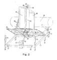
- Fig. 2 illustrates an axonometric view of the device from a different angle
- Fig. 3 illustrates an exploded side view of a detail of the device.
- 1 indicates the frame of the device for heating a fluid through solar energy.
- the frame 1 is equipped with feet 2 necessary for the installation on a horizontal plane or for the anchorage to brackets prearranged in case of inclined planets.
- the base frame On the base frame are arranged the ringbolts 3, useful to fix possible tie rods, the buffers 4, the control unit 5 seated inside a tight box and underneath it the fixed part of the actuator 6.
- the base frame On an inner crossbeam of the frame some hinges 7 are mounted, to which is fixed one side of the inclinable plane 8, which can vary its inclination through the actuator 6.
- the excursion limits are imposed by electrical limit switch, inside the actuator 6, and mechanic stops, consisting for example of buffers 4 and pins 9 (only one illustrated).
- a cylinder 12 is fixed, thanks to a robust socket 11. From the lower end of the cylinder 12 come out supply and output pipes 13, while on the upper end a relief valve 14 is coaxially mounted, well secured.
- a temperature sensor 15 is provided, placed either on the outside of the cylinder, as illustrated, or inside it. According to the materials used and to the type of use, it may also be necessary, inside the cylinder, to install a corrosion-proofing cathode (not illustrated).
- the supply and outlet pipes of the cylinder are connected with two hoses 16 directly to the mouths 17 hot-cold fixed to the inner crossbeam (this is the configuration of the direct heating of the fluid or where an exchanger is used different from the one equipped). If however the use the equipped exchanger, with interposed pump and possible expansion tank, is desired, the hoses will have to be connected to this element.
- the circular plane 18 Above the inclinable plane, outside the socket, the circular plane 18 is mounted. Thanks to a series of bearings (or other revolving members), some of which mounted on a specific ring 19, the circular plane is maintained rested on the plane, centered as regards the axis of the cylinder but free to turn through an engine 20.
- the space between the circular plane and the plane below hosts and protects the mechanical transmission members, which can be inspected only through the manhole 21.
- the circular plane rotates to follow the apparent motion of the sun from morning to evening, limited in extreme positions by electrical and mechanical limit switch.
- a cover 25 also of rigid material and heat-insulating, which houses, at the centre, in an appropriate seat 26, a roller bearing 27 whose inner part is inserted into the body of the relief valve 14.
- the bearing is mechanically connected but electrically isolated with appropriate insulator both towards the valve and towards the cover. This bearing serves multiple functions:
- a series of brackets 28 anchored to the circular crown is meant to hold the mirror and the rear part of the cover.
- a small photovoltaic panel 29 meant to provide all electricity required by the control and movement members.
- a position sensor 30 is mounted, which generates the piece of information required to follow the sun.
- a circuit 32 that elaborates the pieces of information and mixes them with the direct current produced by the panel.
- the roller bearing transfers all this to a wire 33 that runs parallel to the cylinder, comes out of a hole underneath the socket, and with other wires finally comes to the electronic control unit.
- This equipped with a battery, serves mainly to the following functions:
- the diameter ratio of the cylinder which may be a tank, a serpentine or any other enhancing element
- the area of the overall tapping it is possible to shift from the field of low temperatures (below 100 °C) to medium ones (between 100 and 250 °C).
- applications of the object may be many, such as:
- the claimed device reaches the aim to capture, in perfect autonomy, the whole solar energy that hits it. This is obtained in particular thanks to the fact that there are electromechanical members that maintain it always oriented in the more favorable direction. This gives it a definitely higher efficiency compared to the one of the traditional fixed collectors, with equal surface committed.
- heat exchanger 10 is placed rocking on the opposite side of the mobile plane (8), in order to reduce the effort of the actuator in the first ascending part, the more difficult, and therefore also its sizing in the project.
- roller bearing 27 is suitable to assure the electrical continuity between the fixed part and the mobile one. This function may also be carried out by means of cables, which though inevitably twist themselves and therefore wear quickly, either by means of sliding contacts, which wear out with time and which however unnecessarily increase the complexity of the mechanism.
Landscapes
- Engineering & Computer Science (AREA)
- Chemical & Material Sciences (AREA)
- Life Sciences & Earth Sciences (AREA)
- Sustainable Development (AREA)
- Sustainable Energy (AREA)
- Thermal Sciences (AREA)
- Physics & Mathematics (AREA)
- Combustion & Propulsion (AREA)
- Mechanical Engineering (AREA)
- General Engineering & Computer Science (AREA)
- Photovoltaic Devices (AREA)
- Heat-Pump Type And Storage Water Heaters (AREA)
- Details Of Aerials (AREA)
Claims (10)
- Vorrichtung zum Erhitzen eines Fluids mit Hilfe von Sonnenenergie, umfassend- einen Zylinder (12), der das zu erhitzende Fluid aufnehmen kann;- einen Parabolspiegel (24), dessen Brennpunkt auf der Achse des Zylinders (12) liegt, um die ihn bestrahlende Sonnenenergie auf den Zylinder zu bündeln;- eine kreisrunde Platte (18), die den Spiegel (24) trägt und von einem Motor (20) in Drehung versetzt werden kann,wobei diese Vorrichtung dadurch gekennzeichnet ist, dass sie eine auf Befehl von Aktuatormitteln (6) neigbare Platte (8) umfasst, welche die aus dem Zylinder (12), dem Spiegel (24) und der kreisrunden Platte (18) gebildete Baugruppe trägt, um den Höhenwinkel in Bezug auf die waagrechte Ebene zu optimieren;- ein Solarpaneel (29), das die von den Steuer- und Bewegungselementen benötigte elektrische Energie liefern kann, wobei das Solarpaneel auf den drehbaren Teil montiert ist, damit es stets in der Position der maximalen Ausbeute ausgerichtet bleibt;- einen Austauscher (10), der als Ausgleichsgewicht auf der der beweglichen Platte (8) gegenüberliegenden Seite so angeordnet ist, dass der Aktuator (6) bei der Abwärtsbewegung durch das Gewicht dieses Austauschers (10) unterstützt wird;- eine aus einem Teil der Platte (18), dem Spiegel (24), einer transparenten Platte (22), zwei Seitenwänden und einem Deckel bestehende Kammer, die einerseits die in ihrem Innern eingeschlossenen Teile sauber und gegen äußere Einflüsse geschützt hält und andererseits verhindert, dass dem Zylinder Wärme entzogen wird, wobei der Zylinder (12) in der Kammer eingeschlossen ist.
- Vorrichtung nach Anspruch 1, dadurch gekennzeichnet, dass es, wenn man von einer geringfügigen Variation des Krümmungsradius von zwei Schläuchen absieht, zwischen den beweglichen und den festen Teilen weder Schläuche noch Stromkabel gibt, die sich verdrehen, wenn sich die Platte (8) neigt.
- Vorrichtung nach Anspruch 1, dadurch gekennzeichnet, dass sich nur der Parabolspiegel (24) dreht, um seine Achse zur Sonne hin ausgerichtet zu halten, während sich der Zylinder (12) zusammen mit dem Spiegel neigt, ohne sich jedoch zu drehen.
- Vorrichtung nach Anspruch 1, dadurch gekennzeichnet, dass sie ein Rollenlager (27) umfasst, das einerseits den festen Teil (14) mit dem beweglichen Teil (25) verbindet und andererseits zum Teil das Gewicht des Zylinders (12) trägt.
- Vorrichtung nach Anspruch 4, dadurch gekennzeichnet, dass das Rollenlager (27) das mühelose Abnehmen des Deckels (25) ermöglicht.
- Vorrichtung nach Anspruch 4, dadurch gekennzeichnet, dass das Rollenlager (27) dem Zylinder (12) gestattet, sich aufgrund der Wärmeausdehnungen auszudehnen.
- Vorrichtung nach Anspruch 4, dadurch gekennzeichnet, dass das Rollenlager (27) geeignet ist, den elektrischen Durchgang zwischen dem festen und dem beweglichen Teil zu gewährleisten.
- Vorrichtung nach Anspruch 1, dadurch gekennzeichnet, dass sie ein Entlüftungsventil (14) umfasst, das den oberen mechanischen Zapfen des Zylinders (12) bildet, da es auf seine Achse montiert ist.
- Vorrichtung nach Anspruch 8, dadurch gekennzeichnet, dass auf dem Körper des Entlüftungsventils (14) der innere Teil des Rollenlagers (27) untergebracht ist.
- Vorrichtung nach Anspruch 1, dadurch gekennzeichnet, dass sie eine Reihe von Lagern oder anderen Wälzmitteln umfasst, welche die kreisrunde Platte (18) an die neigbare Platte (8) binden und ihr nur eine Kreisbewegung gestatten.
Applications Claiming Priority (2)
| Application Number | Priority Date | Filing Date | Title |
|---|---|---|---|
| IT000006U ITFO20070006U1 (it) | 2007-08-03 | 2007-08-03 | Meccanismo per riscaldare un fluido a mezzo di energia solare, con inseguimento |
| PCT/IB2008/053095 WO2009019643A2 (en) | 2007-08-03 | 2008-08-01 | Device for heating a fluid through solar energy |
Publications (2)
| Publication Number | Publication Date |
|---|---|
| EP2176602A2 EP2176602A2 (de) | 2010-04-21 |
| EP2176602B1 true EP2176602B1 (de) | 2011-10-19 |
Family
ID=40166162
Family Applications (1)
| Application Number | Title | Priority Date | Filing Date |
|---|---|---|---|
| EP08789522A Not-in-force EP2176602B1 (de) | 2007-08-03 | 2008-08-01 | Vorrichtung zum erwärmen eines fluids durch sonnenenergie |
Country Status (5)
| Country | Link |
|---|---|
| EP (1) | EP2176602B1 (de) |
| AT (1) | ATE529709T1 (de) |
| ES (1) | ES2373506T3 (de) |
| IT (1) | ITFO20070006U1 (de) |
| WO (1) | WO2009019643A2 (de) |
Families Citing this family (1)
| Publication number | Priority date | Publication date | Assignee | Title |
|---|---|---|---|---|
| WO2010013270A1 (en) * | 2008-07-31 | 2010-02-04 | Green Earth S.R.L. | Rotating linear focused thermal energy solar concentrator with vertically inclinable axis |
Citations (2)
| Publication number | Priority date | Publication date | Assignee | Title |
|---|---|---|---|---|
| US4291677A (en) * | 1977-12-27 | 1981-09-29 | Monk Robert J | Solar energy collector |
| US4307711A (en) * | 1980-02-25 | 1981-12-29 | Doundoulakis George J | Sun tracking solar energy collector system |
Family Cites Families (7)
| Publication number | Priority date | Publication date | Assignee | Title |
|---|---|---|---|---|
| US2247830A (en) * | 1938-07-07 | 1941-07-01 | Charles G Abbot | Solar heater |
| FR2257067A1 (en) * | 1974-01-04 | 1975-08-01 | Pages Michel | Sun's energy collector device - has paraboloid mirror focussing rays on liquid flow heat exchanger |
| US4351319A (en) * | 1979-08-17 | 1982-09-28 | Robbins Jr Roland W | Radiant energy tracker |
| AU549379B2 (en) * | 1979-09-07 | 1986-01-23 | Magule Pty. Ltd. | Solar energy collector |
| GB2147408A (en) * | 1983-10-04 | 1985-05-09 | Dimos Maglaras | Solar water heater |
| US4587952A (en) * | 1985-05-10 | 1986-05-13 | Richardson John L | Passive solar water heater |
| US4644933A (en) * | 1985-10-28 | 1987-02-24 | Gregory Samuel T | Solar system |
-
2007
- 2007-08-03 IT IT000006U patent/ITFO20070006U1/it unknown
-
2008
- 2008-08-01 WO PCT/IB2008/053095 patent/WO2009019643A2/en not_active Ceased
- 2008-08-01 AT AT08789522T patent/ATE529709T1/de active
- 2008-08-01 EP EP08789522A patent/EP2176602B1/de not_active Not-in-force
- 2008-08-01 ES ES08789522T patent/ES2373506T3/es active Active
Patent Citations (2)
| Publication number | Priority date | Publication date | Assignee | Title |
|---|---|---|---|---|
| US4291677A (en) * | 1977-12-27 | 1981-09-29 | Monk Robert J | Solar energy collector |
| US4307711A (en) * | 1980-02-25 | 1981-12-29 | Doundoulakis George J | Sun tracking solar energy collector system |
Also Published As
| Publication number | Publication date |
|---|---|
| WO2009019643A4 (en) | 2009-06-04 |
| WO2009019643A2 (en) | 2009-02-12 |
| ES2373506T3 (es) | 2012-02-06 |
| ATE529709T1 (de) | 2011-11-15 |
| WO2009019643A3 (en) | 2009-04-02 |
| EP2176602A2 (de) | 2010-04-21 |
| ITFO20070006U1 (it) | 2007-11-02 |
Similar Documents
| Publication | Publication Date | Title |
|---|---|---|
| US4088120A (en) | Solar concentrator-collector | |
| CN2913955Y (zh) | 可自散热的太阳能聚集型光伏发电装置 | |
| US4284839A (en) | Internal refractor focusing solar energy collector apparatus and method | |
| CA2590165C (en) | Solar energy collection system | |
| US20110259318A1 (en) | Two-Stage Solar Concentrating System | |
| US20100206302A1 (en) | Rotational Trough Reflector Array For Solar-Electricity Generation | |
| TW201109601A (en) | Apparatus and system to lower cost per watt with concentrated linear solar panel | |
| US20120174966A1 (en) | Concentrating tracking solar energy collector | |
| KR20110048548A (ko) | 태양 에너지 변환 | |
| US20080308152A1 (en) | Solar collector with angled cooling fins | |
| WO1982001934A1 (en) | Variable entropy solar energy harvester | |
| CN101098112A (zh) | 可自散热的太阳能聚集型光伏发电装置 | |
| US20100043777A1 (en) | Solar collector system | |
| WO2018083506A1 (en) | Concentrating solar system of 3 suns for the simultaneous production of electrical, cooling and thermal energy for buildings | |
| US20130327400A1 (en) | Direct solar-radiation collection and concentration element and panel | |
| US20120186575A1 (en) | Solar Collector | |
| US20140261392A1 (en) | Solar Collector | |
| Kalogirou | Recent patents in solar energy collectors and applications | |
| JP2005106432A (ja) | ソーラ集光集熱器 | |
| US8030605B2 (en) | Method and device for the utilization of solar energy | |
| US20110240097A1 (en) | Concentrating solar energy collector system with photovoltaic cells | |
| AU2005331708B2 (en) | Thermoelectric solar plant | |
| EP2176602B1 (de) | Vorrichtung zum erwärmen eines fluids durch sonnenenergie | |
| US20140366930A1 (en) | Hybrid solar energy recovery system | |
| CN102725593B (zh) | 太阳能盘集光器系统及相关方法 |
Legal Events
| Date | Code | Title | Description |
|---|---|---|---|
| PUAI | Public reference made under article 153(3) epc to a published international application that has entered the european phase |
Free format text: ORIGINAL CODE: 0009012 |
|
| 17P | Request for examination filed |
Effective date: 20100211 |
|
| AK | Designated contracting states |
Kind code of ref document: A2 Designated state(s): AT BE BG CH CY CZ DE DK EE ES FI FR GB GR HR HU IE IS IT LI LT LU LV MC MT NL NO PL PT RO SE SI SK TR |
|
| AX | Request for extension of the european patent |
Extension state: AL BA MK RS |
|
| 17Q | First examination report despatched |
Effective date: 20100514 |
|
| R17C | First examination report despatched (corrected) |
Effective date: 20100521 |
|
| GRAP | Despatch of communication of intention to grant a patent |
Free format text: ORIGINAL CODE: EPIDOSNIGR1 |
|
| GRAS | Grant fee paid |
Free format text: ORIGINAL CODE: EPIDOSNIGR3 |
|
| GRAA | (expected) grant |
Free format text: ORIGINAL CODE: 0009210 |
|
| DAX | Request for extension of the european patent (deleted) | ||
| AK | Designated contracting states |
Kind code of ref document: B1 Designated state(s): AT BE BG CH CY CZ DE DK EE ES FI FR GB GR HR HU IE IS IT LI LT LU LV MC MT NL NO PL PT RO SE SI SK TR |
|
| REG | Reference to a national code |
Ref country code: GB Ref legal event code: FG4D |
|
| REG | Reference to a national code |
Ref country code: CH Ref legal event code: EP |
|
| REG | Reference to a national code |
Ref country code: IE Ref legal event code: FG4D |
|
| REG | Reference to a national code |
Ref country code: DE Ref legal event code: R096 Ref document number: 602008010640 Country of ref document: DE Effective date: 20111215 |
|
| REG | Reference to a national code |
Ref country code: ES Ref legal event code: FG2A Ref document number: 2373506 Country of ref document: ES Kind code of ref document: T3 Effective date: 20120206 |
|
| REG | Reference to a national code |
Ref country code: NL Ref legal event code: VDEP Effective date: 20111019 |
|
| LTIE | Lt: invalidation of european patent or patent extension |
Effective date: 20111019 |
|
| PG25 | Lapsed in a contracting state [announced via postgrant information from national office to epo] |
Ref country code: LT Free format text: LAPSE BECAUSE OF FAILURE TO SUBMIT A TRANSLATION OF THE DESCRIPTION OR TO PAY THE FEE WITHIN THE PRESCRIBED TIME-LIMIT Effective date: 20111019 Ref country code: BE Free format text: LAPSE BECAUSE OF FAILURE TO SUBMIT A TRANSLATION OF THE DESCRIPTION OR TO PAY THE FEE WITHIN THE PRESCRIBED TIME-LIMIT Effective date: 20111019 Ref country code: NO Free format text: LAPSE BECAUSE OF FAILURE TO SUBMIT A TRANSLATION OF THE DESCRIPTION OR TO PAY THE FEE WITHIN THE PRESCRIBED TIME-LIMIT Effective date: 20120119 Ref country code: IS Free format text: LAPSE BECAUSE OF FAILURE TO SUBMIT A TRANSLATION OF THE DESCRIPTION OR TO PAY THE FEE WITHIN THE PRESCRIBED TIME-LIMIT Effective date: 20120219 |
|
| PG25 | Lapsed in a contracting state [announced via postgrant information from national office to epo] |
Ref country code: PT Free format text: LAPSE BECAUSE OF FAILURE TO SUBMIT A TRANSLATION OF THE DESCRIPTION OR TO PAY THE FEE WITHIN THE PRESCRIBED TIME-LIMIT Effective date: 20120220 Ref country code: NL Free format text: LAPSE BECAUSE OF FAILURE TO SUBMIT A TRANSLATION OF THE DESCRIPTION OR TO PAY THE FEE WITHIN THE PRESCRIBED TIME-LIMIT Effective date: 20111019 Ref country code: SE Free format text: LAPSE BECAUSE OF FAILURE TO SUBMIT A TRANSLATION OF THE DESCRIPTION OR TO PAY THE FEE WITHIN THE PRESCRIBED TIME-LIMIT Effective date: 20111019 Ref country code: SI Free format text: LAPSE BECAUSE OF FAILURE TO SUBMIT A TRANSLATION OF THE DESCRIPTION OR TO PAY THE FEE WITHIN THE PRESCRIBED TIME-LIMIT Effective date: 20111019 Ref country code: HR Free format text: LAPSE BECAUSE OF FAILURE TO SUBMIT A TRANSLATION OF THE DESCRIPTION OR TO PAY THE FEE WITHIN THE PRESCRIBED TIME-LIMIT Effective date: 20111019 Ref country code: LV Free format text: LAPSE BECAUSE OF FAILURE TO SUBMIT A TRANSLATION OF THE DESCRIPTION OR TO PAY THE FEE WITHIN THE PRESCRIBED TIME-LIMIT Effective date: 20111019 Ref country code: GR Free format text: LAPSE BECAUSE OF FAILURE TO SUBMIT A TRANSLATION OF THE DESCRIPTION OR TO PAY THE FEE WITHIN THE PRESCRIBED TIME-LIMIT Effective date: 20120120 |
|
| PG25 | Lapsed in a contracting state [announced via postgrant information from national office to epo] |
Ref country code: CY Free format text: LAPSE BECAUSE OF FAILURE TO SUBMIT A TRANSLATION OF THE DESCRIPTION OR TO PAY THE FEE WITHIN THE PRESCRIBED TIME-LIMIT Effective date: 20111019 |
|
| PG25 | Lapsed in a contracting state [announced via postgrant information from national office to epo] |
Ref country code: CZ Free format text: LAPSE BECAUSE OF FAILURE TO SUBMIT A TRANSLATION OF THE DESCRIPTION OR TO PAY THE FEE WITHIN THE PRESCRIBED TIME-LIMIT Effective date: 20111019 Ref country code: SK Free format text: LAPSE BECAUSE OF FAILURE TO SUBMIT A TRANSLATION OF THE DESCRIPTION OR TO PAY THE FEE WITHIN THE PRESCRIBED TIME-LIMIT Effective date: 20111019 Ref country code: BG Free format text: LAPSE BECAUSE OF FAILURE TO SUBMIT A TRANSLATION OF THE DESCRIPTION OR TO PAY THE FEE WITHIN THE PRESCRIBED TIME-LIMIT Effective date: 20120119 Ref country code: DK Free format text: LAPSE BECAUSE OF FAILURE TO SUBMIT A TRANSLATION OF THE DESCRIPTION OR TO PAY THE FEE WITHIN THE PRESCRIBED TIME-LIMIT Effective date: 20111019 Ref country code: EE Free format text: LAPSE BECAUSE OF FAILURE TO SUBMIT A TRANSLATION OF THE DESCRIPTION OR TO PAY THE FEE WITHIN THE PRESCRIBED TIME-LIMIT Effective date: 20111019 |
|
| REG | Reference to a national code |
Ref country code: CH Ref legal event code: NV Representative=s name: LEMAN CONSULTING S.A. |
|
| PLBE | No opposition filed within time limit |
Free format text: ORIGINAL CODE: 0009261 |
|
| STAA | Information on the status of an ep patent application or granted ep patent |
Free format text: STATUS: NO OPPOSITION FILED WITHIN TIME LIMIT |
|
| PG25 | Lapsed in a contracting state [announced via postgrant information from national office to epo] |
Ref country code: RO Free format text: LAPSE BECAUSE OF FAILURE TO SUBMIT A TRANSLATION OF THE DESCRIPTION OR TO PAY THE FEE WITHIN THE PRESCRIBED TIME-LIMIT Effective date: 20111019 Ref country code: PL Free format text: LAPSE BECAUSE OF FAILURE TO SUBMIT A TRANSLATION OF THE DESCRIPTION OR TO PAY THE FEE WITHIN THE PRESCRIBED TIME-LIMIT Effective date: 20111019 |
|
| 26N | No opposition filed |
Effective date: 20120720 |
|
| REG | Reference to a national code |
Ref country code: DE Ref legal event code: R097 Ref document number: 602008010640 Country of ref document: DE Effective date: 20120720 |
|
| PG25 | Lapsed in a contracting state [announced via postgrant information from national office to epo] |
Ref country code: MC Free format text: LAPSE BECAUSE OF NON-PAYMENT OF DUE FEES Effective date: 20120831 |
|
| REG | Reference to a national code |
Ref country code: IE Ref legal event code: MM4A |
|
| PG25 | Lapsed in a contracting state [announced via postgrant information from national office to epo] |
Ref country code: FI Free format text: LAPSE BECAUSE OF FAILURE TO SUBMIT A TRANSLATION OF THE DESCRIPTION OR TO PAY THE FEE WITHIN THE PRESCRIBED TIME-LIMIT Effective date: 20111019 |
|
| PG25 | Lapsed in a contracting state [announced via postgrant information from national office to epo] |
Ref country code: IE Free format text: LAPSE BECAUSE OF NON-PAYMENT OF DUE FEES Effective date: 20120801 |
|
| PG25 | Lapsed in a contracting state [announced via postgrant information from national office to epo] |
Ref country code: MT Free format text: LAPSE BECAUSE OF FAILURE TO SUBMIT A TRANSLATION OF THE DESCRIPTION OR TO PAY THE FEE WITHIN THE PRESCRIBED TIME-LIMIT Effective date: 20111019 |
|
| PG25 | Lapsed in a contracting state [announced via postgrant information from national office to epo] |
Ref country code: TR Free format text: LAPSE BECAUSE OF FAILURE TO SUBMIT A TRANSLATION OF THE DESCRIPTION OR TO PAY THE FEE WITHIN THE PRESCRIBED TIME-LIMIT Effective date: 20111019 |
|
| PG25 | Lapsed in a contracting state [announced via postgrant information from national office to epo] |
Ref country code: LU Free format text: LAPSE BECAUSE OF NON-PAYMENT OF DUE FEES Effective date: 20120801 |
|
| PG25 | Lapsed in a contracting state [announced via postgrant information from national office to epo] |
Ref country code: HU Free format text: LAPSE BECAUSE OF FAILURE TO SUBMIT A TRANSLATION OF THE DESCRIPTION OR TO PAY THE FEE WITHIN THE PRESCRIBED TIME-LIMIT Effective date: 20080801 |
|
| PGFP | Annual fee paid to national office [announced via postgrant information from national office to epo] |
Ref country code: CH Payment date: 20140820 Year of fee payment: 7 |
|
| REG | Reference to a national code |
Ref country code: CH Ref legal event code: PL |
|
| PG25 | Lapsed in a contracting state [announced via postgrant information from national office to epo] |
Ref country code: CH Free format text: LAPSE BECAUSE OF NON-PAYMENT OF DUE FEES Effective date: 20150831 Ref country code: LI Free format text: LAPSE BECAUSE OF NON-PAYMENT OF DUE FEES Effective date: 20150831 |
|
| REG | Reference to a national code |
Ref country code: FR Ref legal event code: PLFP Year of fee payment: 9 |
|
| REG | Reference to a national code |
Ref country code: FR Ref legal event code: PLFP Year of fee payment: 10 |
|
| REG | Reference to a national code |
Ref country code: DE Ref legal event code: R079 Ref document number: 602008010640 Country of ref document: DE Free format text: PREVIOUS MAIN CLASS: F24J0002340000 Ipc: F24S0060000000 |
|
| REG | Reference to a national code |
Ref country code: FR Ref legal event code: PLFP Year of fee payment: 11 |
|
| PGFP | Annual fee paid to national office [announced via postgrant information from national office to epo] |
Ref country code: AT Payment date: 20180803 Year of fee payment: 11 |
|
| REG | Reference to a national code |
Ref country code: AT Ref legal event code: MM01 Ref document number: 529709 Country of ref document: AT Kind code of ref document: T Effective date: 20190801 |
|
| PG25 | Lapsed in a contracting state [announced via postgrant information from national office to epo] |
Ref country code: AT Free format text: LAPSE BECAUSE OF NON-PAYMENT OF DUE FEES Effective date: 20190801 |
|
| PGFP | Annual fee paid to national office [announced via postgrant information from national office to epo] |
Ref country code: IT Payment date: 20220831 Year of fee payment: 15 Ref country code: GB Payment date: 20220923 Year of fee payment: 15 Ref country code: ES Payment date: 20220923 Year of fee payment: 15 Ref country code: DE Payment date: 20220923 Year of fee payment: 15 |
|
| PGFP | Annual fee paid to national office [announced via postgrant information from national office to epo] |
Ref country code: FR Payment date: 20220830 Year of fee payment: 15 |
|
| REG | Reference to a national code |
Ref country code: DE Ref legal event code: R119 Ref document number: 602008010640 Country of ref document: DE |
|
| GBPC | Gb: european patent ceased through non-payment of renewal fee |
Effective date: 20230801 |
|
| PG25 | Lapsed in a contracting state [announced via postgrant information from national office to epo] |
Ref country code: GB Free format text: LAPSE BECAUSE OF NON-PAYMENT OF DUE FEES Effective date: 20230801 |
|
| PG25 | Lapsed in a contracting state [announced via postgrant information from national office to epo] |
Ref country code: IT Free format text: LAPSE BECAUSE OF NON-PAYMENT OF DUE FEES Effective date: 20230801 Ref country code: GB Free format text: LAPSE BECAUSE OF NON-PAYMENT OF DUE FEES Effective date: 20230801 Ref country code: FR Free format text: LAPSE BECAUSE OF NON-PAYMENT OF DUE FEES Effective date: 20230831 Ref country code: DE Free format text: LAPSE BECAUSE OF NON-PAYMENT OF DUE FEES Effective date: 20240301 |
|
| REG | Reference to a national code |
Ref country code: ES Ref legal event code: FD2A Effective date: 20240927 |
|
| PG25 | Lapsed in a contracting state [announced via postgrant information from national office to epo] |
Ref country code: ES Free format text: LAPSE BECAUSE OF NON-PAYMENT OF DUE FEES Effective date: 20230802 |
|
| PG25 | Lapsed in a contracting state [announced via postgrant information from national office to epo] |
Ref country code: ES Free format text: LAPSE BECAUSE OF NON-PAYMENT OF DUE FEES Effective date: 20230802 |