EP2176116B1 - Scooter type vehicle - Google Patents
Scooter type vehicle Download PDFInfo
- Publication number
- EP2176116B1 EP2176116B1 EP09787909.2A EP09787909A EP2176116B1 EP 2176116 B1 EP2176116 B1 EP 2176116B1 EP 09787909 A EP09787909 A EP 09787909A EP 2176116 B1 EP2176116 B1 EP 2176116B1
- Authority
- EP
- European Patent Office
- Prior art keywords
- frame
- joining part
- head pipe
- vehicle
- front frame
- Prior art date
- Legal status (The legal status is an assumption and is not a legal conclusion. Google has not performed a legal analysis and makes no representation as to the accuracy of the status listed.)
- Active
Links
- 230000003014 reinforcing effect Effects 0.000 description 22
- 239000002828 fuel tank Substances 0.000 description 10
- 239000000446 fuel Substances 0.000 description 7
- 238000005452 bending Methods 0.000 description 4
- 230000005540 biological transmission Effects 0.000 description 4
- 230000008878 coupling Effects 0.000 description 4
- 238000010168 coupling process Methods 0.000 description 4
- 238000005859 coupling reaction Methods 0.000 description 4
- 230000000694 effects Effects 0.000 description 3
- 239000000945 filler Substances 0.000 description 3
- 230000002452 interceptive effect Effects 0.000 description 2
- 238000003466 welding Methods 0.000 description 2
- 230000010354 integration Effects 0.000 description 1
- 239000000725 suspension Substances 0.000 description 1
- 229920003002 synthetic resin Polymers 0.000 description 1
- 239000000057 synthetic resin Substances 0.000 description 1
Images


Classifications
-
- B—PERFORMING OPERATIONS; TRANSPORTING
- B62—LAND VEHICLES FOR TRAVELLING OTHERWISE THAN ON RAILS
- B62K—CYCLES; CYCLE FRAMES; CYCLE STEERING DEVICES; RIDER-OPERATED TERMINAL CONTROLS SPECIALLY ADAPTED FOR CYCLES; CYCLE AXLE SUSPENSIONS; CYCLE SIDE-CARS, FORECARS, OR THE LIKE
- B62K11/00—Motorcycles, engine-assisted cycles or motor scooters with one or two wheels
- B62K11/02—Frames
- B62K11/10—Frames characterised by the engine being over or beside driven rear wheel
-
- B—PERFORMING OPERATIONS; TRANSPORTING
- B62—LAND VEHICLES FOR TRAVELLING OTHERWISE THAN ON RAILS
- B62K—CYCLES; CYCLE FRAMES; CYCLE STEERING DEVICES; RIDER-OPERATED TERMINAL CONTROLS SPECIALLY ADAPTED FOR CYCLES; CYCLE AXLE SUSPENSIONS; CYCLE SIDE-CARS, FORECARS, OR THE LIKE
- B62K19/00—Cycle frames
- B62K19/02—Cycle frames characterised by material or cross-section of frame members
- B62K19/04—Cycle frames characterised by material or cross-section of frame members the material being wholly or mainly metallic, e.g. of high elasticity
- B62K19/06—Cycle frames characterised by material or cross-section of frame members the material being wholly or mainly metallic, e.g. of high elasticity tubular
-
- B—PERFORMING OPERATIONS; TRANSPORTING
- B62—LAND VEHICLES FOR TRAVELLING OTHERWISE THAN ON RAILS
- B62K—CYCLES; CYCLE FRAMES; CYCLE STEERING DEVICES; RIDER-OPERATED TERMINAL CONTROLS SPECIALLY ADAPTED FOR CYCLES; CYCLE AXLE SUSPENSIONS; CYCLE SIDE-CARS, FORECARS, OR THE LIKE
- B62K2202/00—Motorised scooters
Definitions
- the present invention relates to a scooter type vehicle.
- WO 2004/071858 discloses an example of a conventional scooter type vehicle wherein a low-floor footboard is provided between a steering bar for steering the front wheel and a seat where the rider sits.
- a vehicle frame 101 of this scooter type vehicle includes a head pipe 102, a downtube 103, and a pair of left and right side tubes 104, as illustrated in FIG. 12 .
- the head pipe 102 is positioned at the top on the front side of the vehicle body.
- the downtube 103 is joined at the top end to the head pipe 102, and extends rearward and downward.
- the left and right side tubes 104 extend rearward from the bottom part of the downtube 103.
- the side tubes 104 are joined to the downtube 103 by a joining part 105 and are extended rearward and upward while extended outward in the transverse direction of the vehicle.
- a footboard (not shown) is provided over the left and right side tubes 104.
- the downtube 103 is inclined forward at a large angle in a side view of the vehicle body.
- the length A of the downtube 103 in the longitudinal direction of the vehicle is equal to or greater than the length B of the head pipe 102 in the longitudinal direction of the vehicle.
- the joining part 105 between the downtube 103 and the side tubes 104 is located rearward of a rear end line C of the head pipe 102 in the longitudinal direction of the vehicle.
- the downtube 103 is inclined forward at a comparatively large angle as described above, the length of the footboard becomes short in the longitudinal direction. This makes it difficult for a rider to freely position his/her feet on the footboard.
- the wheelbase increases and the vehicle body becomes larger when the length of the footboard in the longitudinal direction is increased by increasing the distance between the front and rear wheels.
- JP 03109130 A discloses a three-wheeled vehicle driven by an electric motor having a plurality of batteries arranged in a battery board having upper and lower lateral frame members surrounding the batteries.
- a first front frame member extends between a lower portion of a head pipe and the lower lateral frame members of the battery board.
- An upper front frame member having a curved shape extends between an upper portion of the head pipe and the front ends of the upper lateral frame members forming the battery board.
- two separate footrests are arranged on each lateral side of the battery board.
- US 5,433,286 A discloses a motorcycle of the scooter-type having a frame body. The frame body comprises lower frame members and a sub-frame arranged above the lower frames.
- Both the lower.frames and the sub-frame are connected to a downtube extending downwardly from a head pipe.
- Two separate footrests are arranged laterally outside of and lower than the sub-frame.
- the downtube is connected to the lowermost end of the head pipe.
- FR 2 855 462 A1 is concerned with an electric vehicle having a frame connected to a lower part of the head pipe.
- a battery box arranged at the lower part of the frame forms a footrest.
- EP 1 914 158 A2 on which the preamble of claim 1 is based discloses a straddle-type vehicle comprising a fuel cell unit arranged between two separate footrest sections arranged laterally outside of a part of a vehicle body surrounding the fuel cell unit.
- a frame includes a straight front frame section connected to a lower part of a head pipe of the straddle-type vehicle.
- the present invention is devised in view of such circumstances, and an object thereof is to provide a scooter type vehicle wherein the footrest space can be kept large without increasing the wheelbase. This object is achieved by a scooter type vehicle in accordance with claim 1.
- FIG. 1 is a left side view of a scooter type vehicle according to Embodiment 1.
- FIG. 2 is a left side view of a vehicle frame alone of the scooter type vehicle
- FIG. 3 is a plan view of the vehicle frame
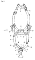
- FIG. 4 is a front view of the vehicle frame as indicated by the arrow IV in FIG. 2 .
- the vehicle frame 2 of the scooter type vehicle 1 is provided with a head pipe 3, a front frame 4, a left rear frame 5, a right rear frame 6, coupling frames 9, 10, 11, and other components.
- the head pipe 3 is a straight tubular member positioned at the top part on the front side of the vehicle frame 2.
- the front frame 4 is a straight tubular member extending downward, while the top end thereof is joined to the head pipe 3.
- the left rear frame 5 extends in a left-rearward direction of the vehicle body, while the front end thereof is joined to an approximately bottom end of the front frame 4.
- the right rear frame 6 extends in a right-rearward direction of the vehicle, while the front end thereof is joined to an approximately bottom end of the front frame 4 in the same manner as the left rear frame 5.
- the coupling frames 9, 10, 11 link the left and right rear frames 5, 6 together in the transverse direction of the vehicle.
- a left joining part 7 the distal end of the left rear frame 5 is joined to the front frame 4, as illustrated in FIG. 4 .
- a right joining part 8 the distal end of the right rear frame 6 is joined to the front frame 4.
- the distal ends of the left and right rear frames 5, 6 are joined at substantially right angles to the left and right side surfaces of the approximately bottom end of the front frame 4 by the left joining part 7 and the right joining part 8 in a front view of the vehicle body.
- the left joining part 7 has a main joining part 16 and a reinforcing member 13.
- the right joining part 8 has a main joining part 17 and a reinforcing member 14.
- the main joining parts 16, 17 are portions for joining the distal ends of the left and right rear frames 5, 6 to the front frame 4.
- the distal ends of the left and right rear frames 5, 6 may be joined to the front frame 4 by welding, for example.
- the left and right main joining parts 16, 17 are vertically positioned at completely separated heights, as illustrated in FIG. 4 .
- the main joining parts 16, 17 may partially overlap in the transverse direction, i.e., may be somewhat misaligned.
- the reinforcing members 13, 14 are joined to the front frame 4 and upper parts of the left and right rear frames 5, 6, as illustrated in FIGS. 2 through 4 .
- the left rear frame 5 is inclined downward as it extends away from the front frame 4
- the right rear frame 6 is inclined upward as it extends away from the front frame 4.
- the height difference is thereby reduced between the outmost parts of the left and right rear frames 5, 6 in the transverse direction of the vehicle.
- reduction in the bank angle to the right side of the vehicle body can be prevented.
- the left joining part 7 and the right joining part 8 overlap with the front frame 4 in a side view of the vehicle body, respectively.
- the left joining part 7 and the right joining part 8 are joined to the front frame 4 so as to be misaligned in the height direction.
- the left rear frame 5 and the left joining part 7 are positioned higher than the right rear frame 6 and the right joining part 8. Therefore, in a side view of the vehicle body (see FIG. 2 ), the front portion of the left rear frame 5 is angled in a downwardly rearward direction, while the front portion of the right rear frame 6 is angled in an upwardly rearward direction.
- left joining part 7 may be positioned lower than the right joining part 8. In this case, in a side view of the vehicle body, the front portion of the right rear frame 6 is angled in a downwardly rearward direction, whereas the front portion of the left rear frame 5 is angled in an upwardly rearward direction.
- a front fork 19 is supported on the head pipe 3, and is allowed to rotate about the head pipe 3.
- a front wheel 18 is rotatably supported on the bottom end of the front fork 19.
- a handle 20 for steering the front wheel 18 is provided at the top end of the front fork 19.
- a headlight 21, a meter panel 22, and other devices are provided in the vicinity of the top end of the front fork 19.
- a front fender 23 for covering the top of the front wheel 18 is fixed to the front fork 19.
- the reinforcing member 15 is provided to the joining part between the head pipe 3 and the front frame 4.
- a seat 26 on which a rider straddles is disposed on the rear portions of the rear frames 5, 6 extending in an upwardly rearward direction of the vehicle body.
- the seat 26 is disposed rearward of the head pipe 3 and the front frame 4.
- a low-floor footboard 27 is disposed between the seat 26 and the handle 20 (head pipe 3). A rider puts his/her feet on the footboard 27 during driving of the vehicle.
- the footboard 27 is disposed above the front portions of the left and right rear frames 5,6.
- a pair of left and right engine brackets 31, 32 is fixed to the coupling frame 9 positioned in the center bottom of the vehicle frame 2.
- a power unit 34 is supported by the engine brackets 31, 32 via link member 33 in a vertically swingable manner.
- the power unit 34 has an engine 35 and a belt transmission device 36 integrally provided to the rear part of the engine 35.
- the power unit 34 is a common model for scooter type vehicles.
- a rear wheel 37 is rotatably supported at the rear part of the belt transmission device 36, and an air cleaner 38 is disposed at the top of the belt transmission device 36. Furthermore, a rear fender 39 is disposed over the rear wheel 37.
- a rear suspension 42 is linked between the rear part of the belt transmission device 36 and a bracket 41.
- the bracket 41 is fixed to the rear part of the left rear frame 5.
- the periphery of the vehicle frame 2 and the power unit 34 are covered with a vehicle body cover 46 made of synthetic resin.
- the outward appearance of the vehicle body is thereby improved and internal devices and the like are protected.
- the vehicle body cover 46 is composed of a plurality of cover members including, e.g., a front cover 47, a leg shield cover 48, a side cover 50, an under cover 51, a rear cover 52 and a rear side cover 53.
- a rear cover part is formed by the rear cover 52 and the rear side cover 53.
- the rear cover part covers underneath the seat 26.
- the interior thereof has an article storage compartment (not shown).
- a taillight 55 and a grab bar 56 are disposed in the rear part of the vehicle.
- a fuel tank 60 is disposed underneath the footboard 27 and between the left and right rear frames 5, 6 of the vehicle frame 2.
- the bottom surface of the fuel tank 60 is covered with a tank guard 61.
- the left and right rear frames 5, 6 and the coupling frame 9 are provided with: footboard fastening brackets 63, 64, 65, 66 to which the footboard 27 is fastened from above with bolts; tank fastening brackets 68, 69, 70, 71 to which the fuel tank 60 is fastened; and guard fastening brackets 73, 74 to which the rear part of the tank guard 61 is fastened.
- a cylindrical guard fastening boss 75 is fixed to the approximately bottom end of the front frame 4.
- the guard fastening boss 75 passes through the approximately bottom end of the front frame 4 in the transverse direction of the vehicle.
- the front part of the tank guard 61 is fastened by a through bolt 76 and a nut 77 to the guard fastening boss 75. Therefore, the bottom end of the front frame 4 and the fuel tank 60 are guarded by the tank guard 61. It is thereby possible to inhibit damage of the components, which is caused by collision with obstructions, ridges and the like on the road that the vehicle travels.
- Fuel is supplied to the fuel tank 60 from a fuel filler tube opening 80 provided in the vicinity of a left center part of the leg shield cover 48.
- the fuel filler tube opening 80 and a fuel supply filler tube 60a provided to the front part of the fuel tank 60 are connected through a fuel pipe (not shown) disposed in the space between the front cover 47 and the leg shield cover 48.
- the front frame 4 of the vehicle frame 2 is angled slightly forward than the right angle in a side view.
- the front frame 4 is also angled for making a length L1 thereof in the longitudinal direction of the vehicle shorter than a length L2 of the head pipe 3 in the longitudinal direction of the vehicle.
- the term "upright state” herein refers to a state that the front wheel 18 and the rear wheel 37 are in contact with the ground and stand perpendicularly to a horizontal plane in a front view of the vehicle body as illustrated in FIG. 1 .
- the term "length in the longitudinal direction of the vehicle” refers to the horizontal length to the ground in a side view of the vehicle body.
- the positional relationship of the members of the scooter type vehicle 1 is described based on the vehicle body being in the upright state.
- the front frame 4 is inclined in a downwardly and rearwardly extending direction in a side view.
- the head pipe 3 is inclined in a downwardly and forwardly extending direction in a side view.
- the inclination angle of the front frame 4 with respect to a vertical line is set to be less than the inclination angle of the head pipe 3 similarly with respect to a vertical line. Additionally, the inclination angle of the front frame 4 is closer to the right angle than that of the head pipe 3.
- an intersection X between an axis C1 of the head pipe 3 and an axis C2 of the front frame 4 is positioned higher than a vertical center M of the head pipe 3.
- a distance T1 from the top end of the head pipe 3 to the intersection X is approximately one third of an entire length T2 of the head pipe 3.
- the distance T 1 is not limited to one third of the entire length T2, and may be arbitrarily set as long as the intersection X is positioned higher than the vertical center M.
- the left joining part 7 and the right joining part 8 are positioned at least partially forward of the rear end of the head pipe 3.
- the reinforcing member 13 of the left joining part 7 and the reinforcing member 14 of the right joining part 8 are positioned forward of a rear end line Lr of the head pipe 3 in the longitudinal direction of the vehicle, as illustrated in FIG. 2 .
- the front fork 19 is provided at a yoke angle A2 of several degrees with respect to the rearward inclination angle A 1 of the head pipe 3, as illustrated in FIG. 1 .
- the yoke angle A2 allows the rearward inclination angle (caster angle) A3 of the front fork 19 to be greater than the rearward inclination angle A1 of the head pipe 3.
- the length L1 of the front frame 4 in the longitudinal direction of the vehicle is less than the length L2 of the head pipe 3 in the longitudinal direction of the vehicle.
- the forward inclination angle of the front frame 4 in a side view of the vehicle body is therefore a steep angle substantially the same as the right angle.
- the forward inclination angle is set to be within 10 degrees of the right angle.
- the joining portion between the front frame 4 and the rear fame 5 is positioned as forward as possible. Accordingly, the footboard 27 is allowed to be enlarged.
- the inclination angle of the front frame 4 is set to be small with respect to the perpendicular line in a side view of the vehicle body, distance between the front frame 4 and the front wheel 18 will be accordingly reduced.
- the intersection X between the axis C1 of the head pipe 3 and the axis C2 of the front frame 4 is positioned higher than the vertical center M of the head pipe 3.
- the left joining part 7 or the right joining part 8 is at least partially disposed forward of the rear end line Lr of the head pipe 3 in the longitudinal direction of the vehicle. Accordingly, the footboard 27 can be extended to the forward. The footboard 27 can thereby be enlarged. Based on the above, the longitudinal dimension S (see FIG. 2 ) of the footboard 27 can be elongated. Accordingly, a large footrest space can be ensured without increasing the wheel base. As a result, a rider is allowed to more freely position his/her feet on the footboard 27.
- the intersection X between the axis C1 of the head pipe 3 and the axis C2 of the front frame 4 is disposed higher than the vertical center M of the head pipe 3. Accordingly, the distance between the front wheel 18 and the footboard 27 can be sufficiently ensured, even when the forward inclination angle of the front frame 4 is set to be a steep angle substantially the same as the right angle. Therefore, enlargement of the wheel base of the scooter type vehicle 1 can be suppressed, and a large longitudinal dimension can be ensured in the footboard 27. As a result, a rider is allowed to more freely position his/her feet on the footboard 27.
- the left and right rear frames 5, 6 are joined to the front frame 4 at substantially right angles. Accordingly, the footboard 27 can be enlarged to a position close to the front frame 4, and the footboard 27 can be enlarged.
- the scooter type vehicle 1 is provided with the left rear frame 5 and the right rear frame 6 as a left and right pair, as described above. Therefore, the height of the footboard 27 is less likely to be increased and the footboard 27 can be formed larger than, e.g., an underbone vehicle frame in which only one rear frame extends rearward from the front frame 4, even if a component, requiring a large space (e.g., a large-capacity fuel tank 60), is disposed underneath the footboard 27.
- a large space e.g., a large-capacity fuel tank 60
- left joining part 7 for joining the left rear frame 5 and front frame 4 and the right joining part 8 for joining the right rear frame 6 and front frame 4 overlap with the front frame 4 in a side view of the vehicle body.
- the left and right rear frames 5, 6 and the footboard 27 are allowed to be further enlarged.
- the left joining part 7 and the right joining part 8 are joined to the front frame 4, while their joining positions are misaligned in terms of height. Therefore, the forward-rearward and left-to-right bending rigidity of the front frame 4 can be markedly improved in comparison with a case that the left and right joining parts 7, 8 are joined to the front frame 4 in the same height positions.
- the reinforcing members 13, 14, provided to the left and right joining parts 7, 8, are thereby allowed to be reduced in size and number. As a result, it is possible to prevent the reinforcing members 13, 14 and other components from interfering with the footboard 27, and the footboard 27 is allowed to be enlarged. Simultaneously, the structure contributes significantly to reduction in the weight and cost of the vehicle frame 2.
- the left joining part 7 and the right joining part 8 are misaligned in the height direction. Accordingly, the aforementioned forward-rearward and left-to-right bending rigidity of the front frame 4 can be enhanced. In particular, the forward-rearward and left-to-right bending rigidity of the front frame 4 can be further increased by disposing the main joining parts 16, 17 at a distance from each other in the height direction.
- a yoke angle A2 is provided to the front fork 19 for increasing the rearward inclination angle A3 of the front fork 19 with respect to the rearward inclination angle A 1 of the head pipe 3.
- the front wheel 18 is thereby prevented from being positioned close to the footboard 27.
- the longitudinal dimension of the footboard 27 can be increased while enlargement of the wheel base of the scooter type vehicle 1 is suppressed.
- the footboard 27 can be ensured to be larger in comparison with cases in which the front frame curves rearward.
- FIG. 5 is a left side view of a vehicle frame alone of a scooter type vehicle according to Embodiment 2 which belongs to the present invention
- FIG. 6 is a front view of the vehicle frame, seen from an arrow VIII in FIG. 5 .
- the configuration of s vehicle frame 82 is substantially the same as that of the vehicle frame 2 of Embodiment 1 illustrated in FIGS. 2 and 3 .
- the components of Embodiment 2 are therefore denoted by the same reference numerals as those of Embodiment 1, and are not hereinafter described.
- the relative positional relationship between the head pipe 3 and the front frame 4 is the same as that of the vehicle frame 2 in Embodiment 1.
- the left rear frame 85 and the right rear frame 86 have a bilaterally asymmetrical shape.
- the left rear frame 85 includes a left lower frame 85a and a left upper frame 85b.
- the right rear frame 86 includes a right lower frame 86a and a right upper frame 86b.
- the distal ends of the left lower frame 85a and the right lower frame 86a are joined at substantially right angles to the left and right side surfaces of an approximately bottom end of the front frame 4 in a front view of the vehicle body.
- the front portions of the left lower frame 85a and the right lower frame 86a are extended rearward, while the rear portions thereof are extend in an upwardly rearward direction.
- the front ends of the left upper frame 85b and the right upper frame 86b are joined at substantially right angles to the left and right side surfaces of the front frame 4 in a front view of the vehicle body.
- the rear ends of the left upper frame 85b and the right upper frame 86b are joined to the top edges of the front portions of the left and right lower frames 85a, 86a.
- the left joining part 87 includes a left lower joining part 87a, a left upper joining part 87b and a reinforcing member 87c.
- the left lower joining part 87a the left lower frame 85a is joined to the front frame 4.
- the left upper joining part 87b the left upper frame 85b is joined to the front frame 4.
- the reinforcing member 87c is disposed between the left upper joining part 87b and the front frame 4.
- the right joining part 88 includes a right lower joining part 88a, a right upper joining part 88b and a reinforcing member 88c.
- the right lower frame 86a is joined to the front frame 4.
- the right upper frame 86b is joined to the front frame 4.
- the reinforcing member 88c is disposed between the right upper joining part 88b and the front frame 4.
- the left and right joining parts 87, 88 at least partially overlap with the front frame 4 in a side view of the vehicle body (see FIG. 5 ).
- the left upper joining part 87b and the right lower joining part 88a are joined to the front frame 4 in different height positions.
- the left lower joining part 87a and the right upper joining part 88b are joined to the front frame 4 in different height positions. Therefore, the forward-rearward and left-to-right bending rigidity of the front frame 4 can be significantly improved in the same manner as the vehicle frame 2 of Embodiment 1.
- the present invention is not limited to the mode of the aforementioned Embodiment 2.
- various other modes are possible for the shapes, positions, and other characteristics of the joining structure of the front frame 4 and the left and right rear frames 5, 6, as well as the reinforcing members 13, 14, 15. Their modes also have same advantageous effects as the aforementioned Embodiments.
- FIGS. 7 and 8 illustrate another case of the first embodiment in which a position of the reinforcing member is changed.
- the reinforcing member 13 of the left rear frame 5 joined to the front frame 4 at a higher position than the right rear frame 6 may be joined to the bottom edge of the left rear frame 5.
- the reinforcing member 14 of the right rear frame 6 joined to the front frame 4 at a lower position than the left rear frame 5 may be joined to the top edge of the right rear frame 6.
- the structure makes it possible to prevent the reinforcing member 13 from easily interfering with the front part of the footboard 27 to be described and to enlarge the footboard 27.
- the reinforcing members 13, 14 are not necessarily essential elements for forming the left joining part 7 and the right joining part 8. Therefore, the reinforcing members 13, 14 may be omitted.
- the reinforcing members 87c, 88c may be similarly omitted by increasing the joining strength of the left lower joining part 87a, the left upper joining part 87b, the right lower joining part 88a and the right upper joining part 88b.
- the position of the fuel tank 60 is not limited to underneath the footboard 27.
- the fuel tank 60 may be disposed underneath the seat 26 or in another position, for example.
- the bottom end of the front frame 4 is extended to a position lower than the lower rear frame joining parts 8, 87a, 88a.
- the bottom end of the front frame 4 may be extended up to the lower rear frame joining parts 8, 87a, 88a.
- the front frame 4 may at least partially include a linear portion.
- the aforementioned intersection X is determined by the intersection between the axis of the head pipe 3 and the extension of the axis of the linear portion of the front frame 4.
- the upper end of the front frame 4 may have a curved shape, as illustrated in FIGS. 9 through 11 .
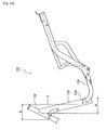
- the intersection X is determined by the intersection between the axis C1 of the head pipe 3 and the extension C2 of the axis of the linear portion of the front frame 4, as illustrated in FIG. 11 .
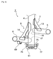
- FIG. 9 is a perspective view of the vehicle frame, seen from a front left position.
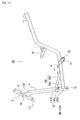
- FIG. 10 is a perspective view of the vehicle frame, seen from a rear right position.
- FIG. 11 is a left side view of the vehicle frame, and the reinforcing member 89, illustrated in FIGS. 9 and 10 , is omitted in FIG. 11 for ease understanding.
- the shape of the top surface of the footboard 27 may not be necessarily formed in a flat shape.
- the top surface of the footboard 27 may be partially protruded upward for avoiding interference with the vehicle frame, the fuel tank, and other structures.
- the footboard 27 may be composed of a pair of right and left footrests and an upwardly-protruding portion interposed between the pair of right and left footrests.
- the head pipe 3 and the front frame 4 are connected by welding.
- the present invention is not limited to this.
- the head pipe 3 and the front frame 4 may be integrally formed.
- components of the vehicle frame 2 are not limited to the aforementioned embodiments.
- the vehicle frame 2 may be composed of a single member formed by integration of a plurality of members.
- the vehicle frame 2 may be composed of a plurality of members separately formed.
- the present invention has an advantageous effect that a large footrest space can be ensured without increasing the wheelbase, and can be used in a scooter type vehicle.
Abstract
Description
- The present invention relates to a scooter type vehicle.
-
WO 2004/071858 discloses an example of a conventional scooter type vehicle wherein a low-floor footboard is provided between a steering bar for steering the front wheel and a seat where the rider sits. - A
vehicle frame 101 of this scooter type vehicle includes ahead pipe 102, adowntube 103, and a pair of left andright side tubes 104, as illustrated inFIG. 12 . Thehead pipe 102 is positioned at the top on the front side of the vehicle body. Thedowntube 103 is joined at the top end to thehead pipe 102, and extends rearward and downward. The left andright side tubes 104 extend rearward from the bottom part of thedowntube 103. Theside tubes 104 are joined to thedowntube 103 by a joiningpart 105 and are extended rearward and upward while extended outward in the transverse direction of the vehicle. A footboard (not shown) is provided over the left andright side tubes 104. - In this type of
conventional vehicle frame 101, thedowntube 103 is inclined forward at a large angle in a side view of the vehicle body. The length A of thedowntube 103 in the longitudinal direction of the vehicle is equal to or greater than the length B of thehead pipe 102 in the longitudinal direction of the vehicle. - Additionally, the joining
part 105 between thedowntube 103 and theside tubes 104 is located rearward of a rear end line C of thehead pipe 102 in the longitudinal direction of the vehicle. - However, since the
downtube 103 is inclined forward at a comparatively large angle as described above, the length of the footboard becomes short in the longitudinal direction. This makes it difficult for a rider to freely position his/her feet on the footboard. On the other hand, the wheelbase increases and the vehicle body becomes larger when the length of the footboard in the longitudinal direction is increased by increasing the distance between the front and rear wheels. -
JP 03109130 A Fig. 4 , two separate footrests are arranged on each lateral side of the battery board.
US 5,433,286 A discloses a motorcycle of the scooter-type having a frame body. The frame body comprises lower frame members and a sub-frame arranged above the lower frames. Both the lower.frames and the sub-frame are connected to a downtube extending downwardly from a head pipe. Two separate footrests are arranged laterally outside of and lower than the sub-frame. The downtube is connected to the lowermost end of the head pipe.
FR 2 855 462 A1
EP 1 914 158 A2 on which the preamble of claim 1 is based, discloses a straddle-type vehicle comprising a fuel cell unit arranged between two separate footrest sections arranged laterally outside of a part of a vehicle body surrounding the fuel cell unit. A frame includes a straight front frame section connected to a lower part of a head pipe of the straddle-type vehicle.
The present invention is devised in view of such circumstances, and an object thereof is to provide a scooter type vehicle wherein the footrest space can be kept large without increasing the wheelbase.
This object is achieved by a scooter type vehicle in accordance with claim 1. - According to the present invention, it is possible to keep the footrest space large without increasing the wheelbase.
-
- [
fig.1]FIG. 1 is a left side view of a scooter type vehicle according to Embodiment 1. - [
fig.2]FIG. 2 is a left side view of a vehicle frame alone of the scooter type vehicle according to Embodiment 1. - [
fig.3]FIG. 3 is a plan view of the vehicle frame alone of the scooter type vehicle according to Embodiment 1. - [
fig.4]FIG. 4 is a front view of the vehicle frame of the scooter type vehicle according to Embodiment 1, seen along an arrow IV inFIG. 2 . - [
fig.5]FIG. 5 is a left side view of a vehicle frame alone of a scooter type vehicle according to Embodiment 2 which belongs to the present invention. - [
fig.6]FIG. 6 is a front view of the vehicle frame of the scooter type vehicle according toEmbodiment 2, seen along an arrow VIII inFIG. 5 . - [
fig.7]FIG. 7 is a perspective view of the vehicle frame of the scooter type vehicle according to another embodiment, seen from a rear left position. - [
fig.8]FIG. 8 is a perspective view the vehicle frame of the scooter type vehicle according to another embodiment, seen from a front left position. - [
fig.9]FIG. 9 is a perspective view of the vehicle frame of the scooter type vehicle according to another embodiment, seen from a front left position. - [
fig.10]FIG. 10 is a perspective view of the vehicle frame of the scooter type vehicle according to another embodiment, seen from a rear right position. - [
fig.11]FIG. 11 is a left side view of the vehicle frame of the scooter type vehicle according to another embodiment. - [
fig.12]FIG. 12 is a side view of a vehicle frame illustrating a conventional art. - Embodiments of the present invention are described hereinbelow with reference to the drawings.
-
FIG. 1 is a left side view of a scooter type vehicle according to Embodiment 1.FIG. 2 is a left side view of a vehicle frame alone of the scooter type vehicle,FIG. 3 is a plan view of the vehicle frame, andFIG. 4 is a front view of the vehicle frame as indicated by the arrow IV inFIG. 2 . - The
vehicle frame 2 of the scooter type vehicle 1 is provided with ahead pipe 3, afront frame 4, a leftrear frame 5, a rightrear frame 6,coupling frames head pipe 3 is a straight tubular member positioned at the top part on the front side of thevehicle frame 2. Thefront frame 4 is a straight tubular member extending downward, while the top end thereof is joined to thehead pipe 3. The leftrear frame 5 extends in a left-rearward direction of the vehicle body, while the front end thereof is joined to an approximately bottom end of thefront frame 4. The rightrear frame 6 extends in a right-rearward direction of the vehicle, while the front end thereof is joined to an approximately bottom end of thefront frame 4 in the same manner as the leftrear frame 5. The coupling frames 9, 10, 11 link the left and rightrear frames - In a
left joining part 7, the distal end of the leftrear frame 5 is joined to thefront frame 4, as illustrated inFIG. 4 . On the other hand, in a right joiningpart 8, the distal end of the rightrear frame 6 is joined to thefront frame 4. The distal ends of the left and rightrear frames front frame 4 by the left joiningpart 7 and the right joiningpart 8 in a front view of the vehicle body. - The left joining
part 7 has a main joiningpart 16 and a reinforcingmember 13. Also, the right joiningpart 8 has a main joiningpart 17 and a reinforcingmember 14. The main joiningparts rear frames front frame 4. The distal ends of the left and rightrear frames front frame 4 by welding, for example. In the present embodiment, the left and right main joiningparts FIG. 4 . However, the main joiningparts - The reinforcing
members front frame 4 and upper parts of the left and right rear frames 5, 6, as illustrated inFIGS. 2 through 4 . As is obvious inFIG. 4 , in a front view of the vehicle body, the leftrear frame 5 is inclined downward as it extends away from thefront frame 4, and the rightrear frame 6 is inclined upward as it extends away from thefront frame 4. The height difference is thereby reduced between the outmost parts of the left and right rear frames 5, 6 in the transverse direction of the vehicle. Moreover, with the low-height rightrear frame 6, reduction in the bank angle to the right side of the vehicle body can be prevented. - The
left joining part 7 and theright joining part 8 overlap with thefront frame 4 in a side view of the vehicle body, respectively. Theleft joining part 7 and theright joining part 8 are joined to thefront frame 4 so as to be misaligned in the height direction. In the present embodiment, for example, the leftrear frame 5 and theleft joining part 7 are positioned higher than the rightrear frame 6 and theright joining part 8. Therefore, in a side view of the vehicle body (seeFIG. 2 ), the front portion of the leftrear frame 5 is angled in a downwardly rearward direction, while the front portion of the rightrear frame 6 is angled in an upwardly rearward direction. Conversely, left joiningpart 7 may be positioned lower than theright joining part 8. In this case, in a side view of the vehicle body, the front portion of the rightrear frame 6 is angled in a downwardly rearward direction, whereas the front portion of the leftrear frame 5 is angled in an upwardly rearward direction. - A
front fork 19 is supported on thehead pipe 3, and is allowed to rotate about thehead pipe 3. Afront wheel 18 is rotatably supported on the bottom end of thefront fork 19. Ahandle 20 for steering thefront wheel 18 is provided at the top end of thefront fork 19. Aheadlight 21, ameter panel 22, and other devices are provided in the vicinity of the top end of thefront fork 19. Afront fender 23 for covering the top of thefront wheel 18 is fixed to thefront fork 19. The reinforcingmember 15 is provided to the joining part between thehead pipe 3 and thefront frame 4. - A
seat 26 on which a rider straddles is disposed on the rear portions of therear frames seat 26 is disposed rearward of thehead pipe 3 and thefront frame 4. A low-floor footboard 27 is disposed between theseat 26 and the handle 20 (head pipe 3). A rider puts his/her feet on thefootboard 27 during driving of the vehicle. - The
footboard 27 is disposed above the front portions of the left and right rear frames 5,6. - A pair of left and
right engine brackets coupling frame 9 positioned in the center bottom of thevehicle frame 2. Apower unit 34 is supported by theengine brackets link member 33 in a vertically swingable manner. Thepower unit 34 has anengine 35 and abelt transmission device 36 integrally provided to the rear part of theengine 35. Thepower unit 34 is a common model for scooter type vehicles. Arear wheel 37 is rotatably supported at the rear part of thebelt transmission device 36, and anair cleaner 38 is disposed at the top of thebelt transmission device 36. Furthermore, arear fender 39 is disposed over therear wheel 37. - Furthermore, a
rear suspension 42 is linked between the rear part of thebelt transmission device 36 and abracket 41. Thebracket 41 is fixed to the rear part of the leftrear frame 5. - The periphery of the
vehicle frame 2 and thepower unit 34 are covered with a vehicle body cover 46 made of synthetic resin. The outward appearance of the vehicle body is thereby improved and internal devices and the like are protected. Thevehicle body cover 46 is composed of a plurality of cover members including, e.g., afront cover 47, aleg shield cover 48, aside cover 50, an undercover 51, arear cover 52 and arear side cover 53. - A rear cover part is formed by the
rear cover 52 and therear side cover 53. The rear cover part covers underneath theseat 26. The interior thereof has an article storage compartment (not shown). Ataillight 55 and agrab bar 56 are disposed in the rear part of the vehicle. - A fuel tank 60 is disposed underneath the
footboard 27 and between the left and right rear frames 5, 6 of thevehicle frame 2. The bottom surface of the fuel tank 60 is covered with atank guard 61. - The left and right rear frames 5, 6 and the
coupling frame 9 are provided with:footboard fastening brackets footboard 27 is fastened from above with bolts;tank fastening brackets guard fastening brackets tank guard 61 is fastened. - A cylindrical
guard fastening boss 75 is fixed to the approximately bottom end of thefront frame 4. Theguard fastening boss 75 passes through the approximately bottom end of thefront frame 4 in the transverse direction of the vehicle. The front part of thetank guard 61 is fastened by a throughbolt 76 and anut 77 to theguard fastening boss 75. Therefore, the bottom end of thefront frame 4 and the fuel tank 60 are guarded by thetank guard 61. It is thereby possible to inhibit damage of the components, which is caused by collision with obstructions, ridges and the like on the road that the vehicle travels. - Fuel is supplied to the fuel tank 60 from a fuel
filler tube opening 80 provided in the vicinity of a left center part of theleg shield cover 48. The fuelfiller tube opening 80 and a fuelsupply filler tube 60a provided to the front part of the fuel tank 60 are connected through a fuel pipe (not shown) disposed in the space between thefront cover 47 and theleg shield cover 48. - As illustrated in
FIG. 2 , thefront frame 4 of thevehicle frame 2 is angled slightly forward than the right angle in a side view. In an upright state, thefront frame 4 is also angled for making a length L1 thereof in the longitudinal direction of the vehicle shorter than a length L2 of thehead pipe 3 in the longitudinal direction of the vehicle. The term "upright state" herein refers to a state that thefront wheel 18 and therear wheel 37 are in contact with the ground and stand perpendicularly to a horizontal plane in a front view of the vehicle body as illustrated inFIG. 1 . Additionally, the term "length in the longitudinal direction of the vehicle" refers to the horizontal length to the ground in a side view of the vehicle body. In the present embodiment, the positional relationship of the members of the scooter type vehicle 1 is described based on the vehicle body being in the upright state. Thefront frame 4 is inclined in a downwardly and rearwardly extending direction in a side view. Thehead pipe 3 is inclined in a downwardly and forwardly extending direction in a side view. In the present embodiment, the inclination angle of thefront frame 4 with respect to a vertical line is set to be less than the inclination angle of thehead pipe 3 similarly with respect to a vertical line. Additionally, the inclination angle of thefront frame 4 is closer to the right angle than that of thehead pipe 3. - In a side view of the vehicle body, an intersection X between an axis C1 of the
head pipe 3 and an axis C2 of thefront frame 4 is positioned higher than a vertical center M of thehead pipe 3. For example, in the present embodiment, a distance T1 from the top end of thehead pipe 3 to the intersection X is approximately one third of an entire length T2 of thehead pipe 3. However, the distance T 1 is not limited to one third of the entire length T2, and may be arbitrarily set as long as the intersection X is positioned higher than the vertical center M. - Furthermore, the
left joining part 7 and theright joining part 8 are positioned at least partially forward of the rear end of thehead pipe 3. In other words, the reinforcingmember 13 of theleft joining part 7 and the reinforcingmember 14 of theright joining part 8 are positioned forward of a rear end line Lr of thehead pipe 3 in the longitudinal direction of the vehicle, as illustrated inFIG. 2 . - The
front fork 19 is provided at a yoke angle A2 of several degrees with respect to the rearward inclination angle A 1 of thehead pipe 3, as illustrated inFIG. 1 . The yoke angle A2 allows the rearward inclination angle (caster angle) A3 of thefront fork 19 to be greater than the rearward inclination angle A1 of thehead pipe 3. - In this scooter type vehicle 1, the length L1 of the
front frame 4 in the longitudinal direction of the vehicle is less than the length L2 of thehead pipe 3 in the longitudinal direction of the vehicle. The forward inclination angle of thefront frame 4 in a side view of the vehicle body is therefore a steep angle substantially the same as the right angle. In the present embodiment, the forward inclination angle is set to be within 10 degrees of the right angle. - Therefore, in a plan view of the vehicle body, the joining portion between the
front frame 4 and therear fame 5 is positioned as forward as possible. Accordingly, thefootboard 27 is allowed to be enlarged. On the other hand, when the inclination angle of thefront frame 4 is set to be small with respect to the perpendicular line in a side view of the vehicle body, distance between thefront frame 4 and thefront wheel 18 will be accordingly reduced. According to the scooter type vehicle of the present embodiment, the intersection X between the axis C1 of thehead pipe 3 and the axis C2 of thefront frame 4 is positioned higher than the vertical center M of thehead pipe 3. With the structure, it is possible to ensure sufficient distance from the front end of theheadpipe 3 to the front end of thefront frame 4 in the longitudinal direction of the vehicle. As a result, even when the inclination angle of thefront frame 4 with respect to the perpendicular line is set to be small in a side view of the vehicle, it is possible to ensure sufficient distance between thefront wheel 18 and thefront frame 4. - Moreover, the
left joining part 7 or theright joining part 8 is at least partially disposed forward of the rear end line Lr of thehead pipe 3 in the longitudinal direction of the vehicle. Accordingly, thefootboard 27 can be extended to the forward. Thefootboard 27 can thereby be enlarged. Based on the above, the longitudinal dimension S (seeFIG. 2 ) of thefootboard 27 can be elongated. Accordingly, a large footrest space can be ensured without increasing the wheel base. As a result, a rider is allowed to more freely position his/her feet on thefootboard 27. - Furthermore, in a side view of the vehicle body, the intersection X between the axis C1 of the
head pipe 3 and the axis C2 of thefront frame 4 is disposed higher than the vertical center M of thehead pipe 3. Accordingly, the distance between thefront wheel 18 and thefootboard 27 can be sufficiently ensured, even when the forward inclination angle of thefront frame 4 is set to be a steep angle substantially the same as the right angle. Therefore, enlargement of the wheel base of the scooter type vehicle 1 can be suppressed, and a large longitudinal dimension can be ensured in thefootboard 27. As a result, a rider is allowed to more freely position his/her feet on thefootboard 27. - The left and right rear frames 5, 6 are joined to the
front frame 4 at substantially right angles. Accordingly, thefootboard 27 can be enlarged to a position close to thefront frame 4, and thefootboard 27 can be enlarged. - In addition, the scooter type vehicle 1 is provided with the left
rear frame 5 and the rightrear frame 6 as a left and right pair, as described above. Therefore, the height of thefootboard 27 is less likely to be increased and thefootboard 27 can be formed larger than, e.g., an underbone vehicle frame in which only one rear frame extends rearward from thefront frame 4, even if a component, requiring a large space (e.g., a large-capacity fuel tank 60), is disposed underneath thefootboard 27. - Moreover, the
left joining part 7 for joining the leftrear frame 5 andfront frame 4, and theright joining part 8 for joining the rightrear frame 6 andfront frame 4, overlap with thefront frame 4 in a side view of the vehicle body. The left and right rear frames 5, 6 and thefootboard 27 are allowed to be further enlarged. - Furthermore, the
left joining part 7 and theright joining part 8 are joined to thefront frame 4, while their joining positions are misaligned in terms of height. Therefore, the forward-rearward and left-to-right bending rigidity of thefront frame 4 can be markedly improved in comparison with a case that the left and right joiningparts front frame 4 in the same height positions. The reinforcingmembers parts members footboard 27, and thefootboard 27 is allowed to be enlarged. Simultaneously, the structure contributes significantly to reduction in the weight and cost of thevehicle frame 2. - In addition, according to the present embodiment, the
left joining part 7 and theright joining part 8 are misaligned in the height direction. Accordingly, the aforementioned forward-rearward and left-to-right bending rigidity of thefront frame 4 can be enhanced. In particular, the forward-rearward and left-to-right bending rigidity of thefront frame 4 can be further increased by disposing the main joiningparts - In a side view of the vehicle body, a yoke angle A2 is provided to the
front fork 19 for increasing the rearward inclination angle A3 of thefront fork 19 with respect to the rearward inclination angle A 1 of thehead pipe 3. Thefront wheel 18 is thereby prevented from being positioned close to thefootboard 27. Moreover, the longitudinal dimension of thefootboard 27 can be increased while enlargement of the wheel base of the scooter type vehicle 1 is suppressed. - Moreover, since the
front frame 4 has a straight tubular shape, thefootboard 27 can be ensured to be larger in comparison with cases in which the front frame curves rearward. -
FIG. 5 is a left side view of a vehicle frame alone of a scooter type vehicle according toEmbodiment 2 which belongs to the present invention, andFIG. 6 is a front view of the vehicle frame, seen from an arrow VIII inFIG. 5 . - Excluding a left
rear frame 85, a rightrear frame 86, aleft joining part 87 and aright joining part 88, the configuration of svehicle frame 82 is substantially the same as that of thevehicle frame 2 of Embodiment 1 illustrated inFIGS. 2 and3 . The components ofEmbodiment 2 are therefore denoted by the same reference numerals as those of Embodiment 1, and are not hereinafter described. The relative positional relationship between thehead pipe 3 and thefront frame 4 is the same as that of thevehicle frame 2 in Embodiment 1. - The left
rear frame 85 and the rightrear frame 86 have a bilaterally asymmetrical shape. The leftrear frame 85 includes a leftlower frame 85a and a leftupper frame 85b. The rightrear frame 86 includes a rightlower frame 86a and a rightupper frame 86b. - The distal ends of the left
lower frame 85a and the rightlower frame 86a are joined at substantially right angles to the left and right side surfaces of an approximately bottom end of thefront frame 4 in a front view of the vehicle body. The front portions of the leftlower frame 85a and the rightlower frame 86a are extended rearward, while the rear portions thereof are extend in an upwardly rearward direction. On the other hand, the front ends of the leftupper frame 85b and the rightupper frame 86b are joined at substantially right angles to the left and right side surfaces of thefront frame 4 in a front view of the vehicle body. The rear ends of the leftupper frame 85b and the rightupper frame 86b are joined to the top edges of the front portions of the left and rightlower frames - As illustrated in
FIG. 6 , theleft joining part 87 includes a left lower joiningpart 87a, a leftupper joining part 87b and a reinforcingmember 87c. In the left lower joiningpart 87a, the leftlower frame 85a is joined to thefront frame 4. In the leftupper joining part 87b, the leftupper frame 85b is joined to thefront frame 4. The reinforcingmember 87c is disposed between the leftupper joining part 87b and thefront frame 4. On the other hand, theright joining part 88 includes a right lower joiningpart 88a, a rightupper joining part 88b and a reinforcingmember 88c. In the right lower joiningpart 88a, the rightlower frame 86a is joined to thefront frame 4. In the rightupper joining part 88b, the rightupper frame 86b is joined to thefront frame 4. The reinforcingmember 88c is disposed between the rightupper joining part 88b and thefront frame 4. The left and right joiningparts front frame 4 in a side view of the vehicle body (seeFIG. 5 ). - The left
upper joining part 87b and the right lower joiningpart 88a are joined to thefront frame 4 in different height positions. The left lower joiningpart 87a and the rightupper joining part 88b are joined to thefront frame 4 in different height positions. Therefore, the forward-rearward and left-to-right bending rigidity of thefront frame 4 can be significantly improved in the same manner as thevehicle frame 2 of Embodiment 1. - The present invention is not limited to the mode of the
aforementioned Embodiment 2. For example, various other modes are possible for the shapes, positions, and other characteristics of the joining structure of thefront frame 4 and the left and right rear frames 5, 6, as well as the reinforcingmembers -
FIGS. 7 and8 illustrate another case of the first embodiment in which a position of the reinforcing member is changed. As illustrated inFIGS. 7 and8 , the reinforcingmember 13 of the leftrear frame 5 joined to thefront frame 4 at a higher position than the rightrear frame 6 may be joined to the bottom edge of the leftrear frame 5. Moreover, the reinforcingmember 14 of the rightrear frame 6 joined to thefront frame 4 at a lower position than the leftrear frame 5 may be joined to the top edge of the rightrear frame 6. The structure makes it possible to prevent the reinforcingmember 13 from easily interfering with the front part of thefootboard 27 to be described and to enlarge thefootboard 27. - Furthermore, in Embodiment 1, the reinforcing
members left joining part 7 and theright joining part 8. Therefore, the reinforcingmembers Embodiment 2, the reinforcingmembers part 87a, the leftupper joining part 87b, the right lower joiningpart 88a and the rightupper joining part 88b. - In addition, the position of the fuel tank 60 is not limited to underneath the
footboard 27. The fuel tank 60 may be disposed underneath theseat 26 or in another position, for example. - Furthermore, in the aforementioned Embodiments 1 and 2, the bottom end of the
front frame 4 is extended to a position lower than the lower rearframe joining parts front frame 4 may be extended up to the lower rearframe joining parts - In addition, the
front frame 4 may at least partially include a linear portion. When thefront frame 4 partially includes a curved portion, the aforementioned intersection X is determined by the intersection between the axis of thehead pipe 3 and the extension of the axis of the linear portion of thefront frame 4. For example, the upper end of thefront frame 4 may have a curved shape, as illustrated inFIGS. 9 through 11 . In this case, the intersection X is determined by the intersection between the axis C1 of thehead pipe 3 and the extension C2 of the axis of the linear portion of thefront frame 4, as illustrated inFIG. 11 .FIG. 9 is a perspective view of the vehicle frame, seen from a front left position.FIG. 10 is a perspective view of the vehicle frame, seen from a rear right position.FIG. 11 is a left side view of the vehicle frame, and the reinforcingmember 89, illustrated inFIGS. 9 and10 , is omitted inFIG. 11 for ease understanding. - The shape of the top surface of the
footboard 27 may not be necessarily formed in a flat shape. For example, the top surface of thefootboard 27 may be partially protruded upward for avoiding interference with the vehicle frame, the fuel tank, and other structures. Moreover, thefootboard 27 may be composed of a pair of right and left footrests and an upwardly-protruding portion interposed between the pair of right and left footrests. Furthermore, according to the aforementioned Embodiments 1 and 2, thehead pipe 3 and thefront frame 4 are connected by welding. However, the present invention is not limited to this. For example, thehead pipe 3 and thefront frame 4 may be integrally formed. Moreover, components of thevehicle frame 2 are not limited to the aforementioned embodiments. For example, thevehicle frame 2 may be composed of a single member formed by integration of a plurality of members. Alternatively, thevehicle frame 2 may be composed of a plurality of members separately formed. - The present invention has an advantageous effect that a large footrest space can be ensured without increasing the wheelbase, and can be used in a scooter type vehicle.
-
- 1
- Scooter type vehicle
- 2
- Vehicle frame
- 3
- Head pipe
- 4
- Front frame
- 5
- Left rear frame
- 6
- Right rear frame
- 7
- Left joining part
- 8
- Right joining part
- 13, 14
- Reinforcing members
- 19
- Front fork
- 20
- Handle
- 26
- Seat
- 27
- Footboard
- 34
- Power unit
- 87b
- Left upper joining part
- 87a
- Left lower joining part
- 88b
- Right upper joining part
- 88a
- Right lower joining part
- C1
- Axis of head pipe
- C2
- Axis of front frame
- L1
- Length of front frame in longitudinal direction of vehicle
- L2
- Length of head pipe in longitudinal direction of vehicle
- M
- Vertical center of head pipe
- X
- Intersection between head pipe axis and front frame axis
- A1
- Rearward inclination angle of head pipe
- A3
- Caster angle of front fork
- A2
- Yoke angle
Claims (5)
- A scooter type vehicle (1), comprising:a front wheel (18) and a rear wheel (37);a front fork (19) supporting the front wheel for allowing the front wheel to rotate;a head pipe (3) supporting the front fork for allowing the front fork to rotate;a seat (26) disposed rearward of the head pipe;a footboard (27) disposed below the head pipe and the seat, the footboard disposed between the head pipe and the seat;a front frame (4) being a single tubular member extending downward, the front frame partially including a linear portion, a top end of the front frame joined to the head pipe (3), the front frame having a shorter length than the head pipe in the longitudinal direction of the vehicle (1) in an upright state that the front and rear wheels are in contact with the ground and are perpendicular to a horizontal plane in a front view of the vehicle;a left rear frame (5) and a right rear frame (6), a front end of the rear frames (5, 6) joined to a bottom part of the front frame (4), the left rear frame (5) extending in a left-rearward direction of the vehicle, the right rear frame (6) extending in a right-rearward direction of the vehicle (1); anda joining part (7, 8) for joining the rear frame to the front frame, the joining part at least partially positioned forward of a rear end of the head pipe in the upright state,wherein the joining part has a left joining part (7) for joining the left rear frame (5) and the front frame (4), and a right joining part (8) for joining the right rear frame (6) and the front frame (4),wherein the left joining part (7) has a left upper joining part (87b) and a left lower joining part (87a),the right joining part (8) has a right upper joining part (88b) and a right lower joining part (88a),the footboard (27) is arranged above the front portions of the left and right rear frames (5, 6),the left upper joining part (87b) and the right lower joining part (88a) are misaligned in the height direction, andthe left lower joining part (87a) and the right upper joining part (88a) are misaligned in the height direction,characterized in thatthe left upper and lower joining parts are aligned in the height direction,the right upper and lower joining parts are aligned in the height direction, andan intersection (x) between an extension of an axis (C2) of the linear portion of the front frame and an axis (C1) of the head pipe (3) is positioned higher than a vertical center (M) of the head pipe in a side view of the vehicle (1).
- The scooter type vehicle according to claim 1, wherein the rear frame is joined to the front frame at substantially right angle in the front view of the vehicle.
- The scooter type vehicle according to claim 1, wherein the left joining part (7) and the right joining part (8) overlap with the front frame in the side view of the vehicle.
- The scooter type vehicle according to any one of Claims 1 to 3, wherein the front fork (19) is provided with a yoke angle (A2) to increase the rearward inclination angle (A3) of the front fork to be greater than the rearward inclination angle (A1) of the head pipe.
- The scooter type vehicle according to any one of claim 1 to 4, wherein the front frame is formed in a straight pipe shape.
Applications Claiming Priority (3)
| Application Number | Priority Date | Filing Date | Title |
|---|---|---|---|
| JP2008200112 | 2008-08-01 | ||
| JP2009036379 | 2009-02-19 | ||
| PCT/JP2009/003626 WO2010013482A1 (en) | 2008-08-01 | 2009-07-30 | Scooter type vehicle |
Publications (2)
| Publication Number | Publication Date |
|---|---|
| EP2176116A1 EP2176116A1 (en) | 2010-04-21 |
| EP2176116B1 true EP2176116B1 (en) | 2013-11-20 |
Family
ID=41171292
Family Applications (1)
| Application Number | Title | Priority Date | Filing Date |
|---|---|---|---|
| EP09787909.2A Active EP2176116B1 (en) | 2008-08-01 | 2009-07-30 | Scooter type vehicle |
Country Status (5)
| Country | Link |
|---|---|
| EP (1) | EP2176116B1 (en) |
| CN (1) | CN102056791B (en) |
| ES (1) | ES2440280T3 (en) |
| TW (1) | TWI372700B (en) |
| WO (1) | WO2010013482A1 (en) |
Cited By (1)
| Publication number | Priority date | Publication date | Assignee | Title |
|---|---|---|---|---|
| TWI720619B (en) * | 2018-10-11 | 2021-03-01 | 日商山葉發動機股份有限公司 | Straddled vehicle |
Families Citing this family (8)
| Publication number | Priority date | Publication date | Assignee | Title |
|---|---|---|---|---|
| JP2010215216A (en) * | 2009-02-19 | 2010-09-30 | Yamaha Motor Co Ltd | Motorcycle |
| JP2012201242A (en) * | 2011-03-25 | 2012-10-22 | Honda Motor Co Ltd | Frame structure of saddle-ride type vehicle |
| US9457869B2 (en) * | 2011-11-25 | 2016-10-04 | Honda Motor Co., Ltd. | Electric scooter |
| MX2015003686A (en) * | 2012-09-24 | 2015-06-15 | Yamaha Motor Co Ltd | Vehicle. |
| JP2018058456A (en) * | 2016-10-04 | 2018-04-12 | ヤマハ発動機株式会社 | scooter |
| TWI716749B (en) * | 2018-10-12 | 2021-01-21 | 日商山葉發動機股份有限公司 | Straddle vehicle |
| CN111038632B (en) * | 2018-10-12 | 2021-09-24 | 雅马哈发动机株式会社 | Saddle-ride type vehicle |
| CN113511294A (en) * | 2021-07-14 | 2021-10-19 | 天津爱玛车业科技有限公司 | Electric vehicle frame and electric vehicle |
Family Cites Families (6)
| Publication number | Priority date | Publication date | Assignee | Title |
|---|---|---|---|---|
| US5433286A (en) | 1988-09-27 | 1995-07-18 | Honda Giken Kogyo Kabushiki Kaisha | Motorcycle |
| JP2711733B2 (en) * | 1989-09-21 | 1998-02-10 | 中部電力株式会社 | Electric vehicle |
| JP3481050B2 (en) * | 1996-06-18 | 2003-12-22 | 本田技研工業株式会社 | Frame structure of scooter type vehicle |
| TWI260293B (en) | 2003-02-17 | 2006-08-21 | Yamaha Motor Co Ltd | Frame assembly for vehicle and vehicle having the frame assembly |
| US7249644B2 (en) * | 2003-05-30 | 2007-07-31 | Honda Motor Co., Ltd. | Electric vehicle |
| JP2008100574A (en) * | 2006-10-18 | 2008-05-01 | Yamaha Motor Co Ltd | Motorcycle |
-
2009
- 2009-07-30 ES ES09787909.2T patent/ES2440280T3/en active Active
- 2009-07-30 WO PCT/JP2009/003626 patent/WO2010013482A1/en active Application Filing
- 2009-07-30 EP EP09787909.2A patent/EP2176116B1/en active Active
- 2009-07-30 CN CN200980121232.XA patent/CN102056791B/en active Active
- 2009-07-31 TW TW098126021A patent/TWI372700B/en active
Cited By (1)
| Publication number | Priority date | Publication date | Assignee | Title |
|---|---|---|---|---|
| TWI720619B (en) * | 2018-10-11 | 2021-03-01 | 日商山葉發動機股份有限公司 | Straddled vehicle |
Also Published As
| Publication number | Publication date |
|---|---|
| TW201016528A (en) | 2010-05-01 |
| CN102056791B (en) | 2015-06-24 |
| TWI372700B (en) | 2012-09-21 |
| ES2440280T3 (en) | 2014-01-28 |
| CN102056791A (en) | 2011-05-11 |
| WO2010013482A1 (en) | 2010-02-04 |
| EP2176116A1 (en) | 2010-04-21 |
Similar Documents
| Publication | Publication Date | Title |
|---|---|---|
| EP2176116B1 (en) | Scooter type vehicle | |
| EP2167367B1 (en) | Scooter type vehicle | |
| JP5969232B2 (en) | Radiator hose layout structure for saddle-ride type vehicles | |
| JP5925547B2 (en) | Wind guide structure for saddle-ride type vehicles | |
| JP5916456B2 (en) | Wind exhaust structure for radiators of saddle-ride type vehicles | |
| KR101254909B1 (en) | Saddle type vehicle | |
| EP1783040B1 (en) | Straddle-type vehicle | |
| CA2944815A1 (en) | Saddle type vehicle with co-fastened cushion bracket and fender frame | |
| TWI486278B (en) | Vehicle body structure of saddle-ride-type electric vehicle | |
| JP5560059B2 (en) | Saddle riding | |
| JP5806643B2 (en) | Body cover structure for saddle-ride type vehicles | |
| EP2554464B1 (en) | Motorcycle | |
| JP5893459B2 (en) | Fuel tank and radiator arrangement structure for saddle-ride type vehicles | |
| JP7022774B2 (en) | Saddle-type electric vehicle | |
| JP4503519B2 (en) | Vehicle fuel tank arrangement structure | |
| CN112533820B (en) | Saddle-ride type vehicle | |
| JP5088087B2 (en) | Rear body structure of scooter type vehicle | |
| JP5894826B2 (en) | Lift-up support structure for saddle-ride type vehicles | |
| JP6351172B2 (en) | Car body rear structure | |
| CN216994674U (en) | Saddle-ride type vehicle | |
| EP3543100B1 (en) | Fuel tank arrangement under the step floor of saddle vehicle | |
| JPH0342389A (en) | Running vehicle | |
| JP5706964B2 (en) | Saddle riding motorcycle | |
| JP2016060368A (en) | Rear carrier of saddle riding type vehicle | |
| WO2020178848A1 (en) | Front cover of vehicle |
Legal Events
| Date | Code | Title | Description |
|---|---|---|---|
| PUAI | Public reference made under article 153(3) epc to a published international application that has entered the european phase |
Free format text: ORIGINAL CODE: 0009012 |
|
| 17P | Request for examination filed |
Effective date: 20100208 |
|
| AK | Designated contracting states |
Kind code of ref document: A1 Designated state(s): AT BE BG CH CY CZ DE DK EE ES FI FR GB GR HR HU IE IS IT LI LT LU LV MC MK MT NL NO PL PT RO SE SI SK SM TR |
|
| AX | Request for extension of the european patent |
Extension state: AL BA RS |
|
| 17Q | First examination report despatched |
Effective date: 20100730 |
|
| DAX | Request for extension of the european patent (deleted) | ||
| GRAP | Despatch of communication of intention to grant a patent |
Free format text: ORIGINAL CODE: EPIDOSNIGR1 |
|
| INTG | Intention to grant announced |
Effective date: 20130612 |
|
| GRAS | Grant fee paid |
Free format text: ORIGINAL CODE: EPIDOSNIGR3 |
|
| GRAA | (expected) grant |
Free format text: ORIGINAL CODE: 0009210 |
|
| AK | Designated contracting states |
Kind code of ref document: B1 Designated state(s): AT BE BG CH CY CZ DE DK EE ES FI FR GB GR HR HU IE IS IT LI LT LU LV MC MK MT NL NO PL PT RO SE SI SK SM TR |
|
| REG | Reference to a national code |
Ref country code: GB Ref legal event code: FG4D |
|
| REG | Reference to a national code |
Ref country code: CH Ref legal event code: EP |
|
| REG | Reference to a national code |
Ref country code: AT Ref legal event code: REF Ref document number: 641423 Country of ref document: AT Kind code of ref document: T Effective date: 20131215 |
|
| REG | Reference to a national code |
Ref country code: IE Ref legal event code: FG4D |
|
| REG | Reference to a national code |
Ref country code: DE Ref legal event code: R096 Ref document number: 602009020295 Country of ref document: DE Effective date: 20140116 |
|
| REG | Reference to a national code |
Ref country code: ES Ref legal event code: FG2A Ref document number: 2440280 Country of ref document: ES Kind code of ref document: T3 Effective date: 20140128 |
|
| REG | Reference to a national code |
Ref country code: NL Ref legal event code: VDEP Effective date: 20131120 |
|
| REG | Reference to a national code |
Ref country code: AT Ref legal event code: MK05 Ref document number: 641423 Country of ref document: AT Kind code of ref document: T Effective date: 20131120 |
|
| REG | Reference to a national code |
Ref country code: LT Ref legal event code: MG4D |
|
| PG25 | Lapsed in a contracting state [announced via postgrant information from national office to epo] |
Ref country code: IS Free format text: LAPSE BECAUSE OF FAILURE TO SUBMIT A TRANSLATION OF THE DESCRIPTION OR TO PAY THE FEE WITHIN THE PRESCRIBED TIME-LIMIT Effective date: 20140320 Ref country code: LT Free format text: LAPSE BECAUSE OF FAILURE TO SUBMIT A TRANSLATION OF THE DESCRIPTION OR TO PAY THE FEE WITHIN THE PRESCRIBED TIME-LIMIT Effective date: 20131120 Ref country code: SE Free format text: LAPSE BECAUSE OF FAILURE TO SUBMIT A TRANSLATION OF THE DESCRIPTION OR TO PAY THE FEE WITHIN THE PRESCRIBED TIME-LIMIT Effective date: 20131120 Ref country code: NO Free format text: LAPSE BECAUSE OF FAILURE TO SUBMIT A TRANSLATION OF THE DESCRIPTION OR TO PAY THE FEE WITHIN THE PRESCRIBED TIME-LIMIT Effective date: 20140220 Ref country code: FI Free format text: LAPSE BECAUSE OF FAILURE TO SUBMIT A TRANSLATION OF THE DESCRIPTION OR TO PAY THE FEE WITHIN THE PRESCRIBED TIME-LIMIT Effective date: 20131120 Ref country code: NL Free format text: LAPSE BECAUSE OF FAILURE TO SUBMIT A TRANSLATION OF THE DESCRIPTION OR TO PAY THE FEE WITHIN THE PRESCRIBED TIME-LIMIT Effective date: 20131120 Ref country code: HR Free format text: LAPSE BECAUSE OF FAILURE TO SUBMIT A TRANSLATION OF THE DESCRIPTION OR TO PAY THE FEE WITHIN THE PRESCRIBED TIME-LIMIT Effective date: 20131120 |
|
| PG25 | Lapsed in a contracting state [announced via postgrant information from national office to epo] |
Ref country code: AT Free format text: LAPSE BECAUSE OF FAILURE TO SUBMIT A TRANSLATION OF THE DESCRIPTION OR TO PAY THE FEE WITHIN THE PRESCRIBED TIME-LIMIT Effective date: 20131120 Ref country code: BE Free format text: LAPSE BECAUSE OF FAILURE TO SUBMIT A TRANSLATION OF THE DESCRIPTION OR TO PAY THE FEE WITHIN THE PRESCRIBED TIME-LIMIT Effective date: 20131120 Ref country code: LV Free format text: LAPSE BECAUSE OF FAILURE TO SUBMIT A TRANSLATION OF THE DESCRIPTION OR TO PAY THE FEE WITHIN THE PRESCRIBED TIME-LIMIT Effective date: 20131120 |
|
| PG25 | Lapsed in a contracting state [announced via postgrant information from national office to epo] |
Ref country code: PT Free format text: LAPSE BECAUSE OF FAILURE TO SUBMIT A TRANSLATION OF THE DESCRIPTION OR TO PAY THE FEE WITHIN THE PRESCRIBED TIME-LIMIT Effective date: 20140320 |
|
| PG25 | Lapsed in a contracting state [announced via postgrant information from national office to epo] |
Ref country code: EE Free format text: LAPSE BECAUSE OF FAILURE TO SUBMIT A TRANSLATION OF THE DESCRIPTION OR TO PAY THE FEE WITHIN THE PRESCRIBED TIME-LIMIT Effective date: 20131120 |
|
| REG | Reference to a national code |
Ref country code: DE Ref legal event code: R097 Ref document number: 602009020295 Country of ref document: DE |
|
| PG25 | Lapsed in a contracting state [announced via postgrant information from national office to epo] |
Ref country code: RO Free format text: LAPSE BECAUSE OF FAILURE TO SUBMIT A TRANSLATION OF THE DESCRIPTION OR TO PAY THE FEE WITHIN THE PRESCRIBED TIME-LIMIT Effective date: 20131120 Ref country code: CZ Free format text: LAPSE BECAUSE OF FAILURE TO SUBMIT A TRANSLATION OF THE DESCRIPTION OR TO PAY THE FEE WITHIN THE PRESCRIBED TIME-LIMIT Effective date: 20131120 Ref country code: PL Free format text: LAPSE BECAUSE OF FAILURE TO SUBMIT A TRANSLATION OF THE DESCRIPTION OR TO PAY THE FEE WITHIN THE PRESCRIBED TIME-LIMIT Effective date: 20131120 Ref country code: SK Free format text: LAPSE BECAUSE OF FAILURE TO SUBMIT A TRANSLATION OF THE DESCRIPTION OR TO PAY THE FEE WITHIN THE PRESCRIBED TIME-LIMIT Effective date: 20131120 |
|
| PLBE | No opposition filed within time limit |
Free format text: ORIGINAL CODE: 0009261 |
|
| STAA | Information on the status of an ep patent application or granted ep patent |
Free format text: STATUS: NO OPPOSITION FILED WITHIN TIME LIMIT |
|
| PG25 | Lapsed in a contracting state [announced via postgrant information from national office to epo] |
Ref country code: DK Free format text: LAPSE BECAUSE OF FAILURE TO SUBMIT A TRANSLATION OF THE DESCRIPTION OR TO PAY THE FEE WITHIN THE PRESCRIBED TIME-LIMIT Effective date: 20131120 |
|
| 26N | No opposition filed |
Effective date: 20140821 |
|
| REG | Reference to a national code |
Ref country code: DE Ref legal event code: R097 Ref document number: 602009020295 Country of ref document: DE Effective date: 20140821 |
|
| REG | Reference to a national code |
Ref country code: DE Ref legal event code: R119 Ref document number: 602009020295 Country of ref document: DE |
|
| PG25 | Lapsed in a contracting state [announced via postgrant information from national office to epo] |
Ref country code: LU Free format text: LAPSE BECAUSE OF FAILURE TO SUBMIT A TRANSLATION OF THE DESCRIPTION OR TO PAY THE FEE WITHIN THE PRESCRIBED TIME-LIMIT Effective date: 20140730 Ref country code: SI Free format text: LAPSE BECAUSE OF FAILURE TO SUBMIT A TRANSLATION OF THE DESCRIPTION OR TO PAY THE FEE WITHIN THE PRESCRIBED TIME-LIMIT Effective date: 20131120 |
|
| REG | Reference to a national code |
Ref country code: CH Ref legal event code: PL |
|
| GBPC | Gb: european patent ceased through non-payment of renewal fee |
Effective date: 20140730 |
|
| REG | Reference to a national code |
Ref country code: IE Ref legal event code: MM4A |
|
| PG25 | Lapsed in a contracting state [announced via postgrant information from national office to epo] |
Ref country code: LI Free format text: LAPSE BECAUSE OF NON-PAYMENT OF DUE FEES Effective date: 20140731 Ref country code: CH Free format text: LAPSE BECAUSE OF NON-PAYMENT OF DUE FEES Effective date: 20140731 Ref country code: DE Free format text: LAPSE BECAUSE OF NON-PAYMENT OF DUE FEES Effective date: 20150203 |
|
| REG | Reference to a national code |
Ref country code: DE Ref legal event code: R119 Ref document number: 602009020295 Country of ref document: DE Effective date: 20150203 |
|
| PG25 | Lapsed in a contracting state [announced via postgrant information from national office to epo] |
Ref country code: GB Free format text: LAPSE BECAUSE OF NON-PAYMENT OF DUE FEES Effective date: 20140730 |
|
| PG25 | Lapsed in a contracting state [announced via postgrant information from national office to epo] |
Ref country code: IE Free format text: LAPSE BECAUSE OF NON-PAYMENT OF DUE FEES Effective date: 20140730 |
|
| PG25 | Lapsed in a contracting state [announced via postgrant information from national office to epo] |
Ref country code: MC Free format text: LAPSE BECAUSE OF FAILURE TO SUBMIT A TRANSLATION OF THE DESCRIPTION OR TO PAY THE FEE WITHIN THE PRESCRIBED TIME-LIMIT Effective date: 20131120 Ref country code: SM Free format text: LAPSE BECAUSE OF FAILURE TO SUBMIT A TRANSLATION OF THE DESCRIPTION OR TO PAY THE FEE WITHIN THE PRESCRIBED TIME-LIMIT Effective date: 20131120 |
|
| PG25 | Lapsed in a contracting state [announced via postgrant information from national office to epo] |
Ref country code: BG Free format text: LAPSE BECAUSE OF FAILURE TO SUBMIT A TRANSLATION OF THE DESCRIPTION OR TO PAY THE FEE WITHIN THE PRESCRIBED TIME-LIMIT Effective date: 20131120 Ref country code: GR Free format text: LAPSE BECAUSE OF FAILURE TO SUBMIT A TRANSLATION OF THE DESCRIPTION OR TO PAY THE FEE WITHIN THE PRESCRIBED TIME-LIMIT Effective date: 20140221 Ref country code: MT Free format text: LAPSE BECAUSE OF FAILURE TO SUBMIT A TRANSLATION OF THE DESCRIPTION OR TO PAY THE FEE WITHIN THE PRESCRIBED TIME-LIMIT Effective date: 20131120 Ref country code: CY Free format text: LAPSE BECAUSE OF FAILURE TO SUBMIT A TRANSLATION OF THE DESCRIPTION OR TO PAY THE FEE WITHIN THE PRESCRIBED TIME-LIMIT Effective date: 20131120 |
|
| REG | Reference to a national code |
Ref country code: FR Ref legal event code: PLFP Year of fee payment: 8 |
|
| PG25 | Lapsed in a contracting state [announced via postgrant information from national office to epo] |
Ref country code: TR Free format text: LAPSE BECAUSE OF FAILURE TO SUBMIT A TRANSLATION OF THE DESCRIPTION OR TO PAY THE FEE WITHIN THE PRESCRIBED TIME-LIMIT Effective date: 20131120 Ref country code: HU Free format text: LAPSE BECAUSE OF FAILURE TO SUBMIT A TRANSLATION OF THE DESCRIPTION OR TO PAY THE FEE WITHIN THE PRESCRIBED TIME-LIMIT; INVALID AB INITIO Effective date: 20090730 |
|
| REG | Reference to a national code |
Ref country code: FR Ref legal event code: PLFP Year of fee payment: 9 |
|
| PG25 | Lapsed in a contracting state [announced via postgrant information from national office to epo] |
Ref country code: MK Free format text: LAPSE BECAUSE OF FAILURE TO SUBMIT A TRANSLATION OF THE DESCRIPTION OR TO PAY THE FEE WITHIN THE PRESCRIBED TIME-LIMIT Effective date: 20131120 |
|
| REG | Reference to a national code |
Ref country code: FR Ref legal event code: PLFP Year of fee payment: 10 |
|
| PGFP | Annual fee paid to national office [announced via postgrant information from national office to epo] |
Ref country code: ES Payment date: 20200922 Year of fee payment: 12 |
|
| REG | Reference to a national code |
Ref country code: ES Ref legal event code: FD2A Effective date: 20221028 |
|
| PG25 | Lapsed in a contracting state [announced via postgrant information from national office to epo] |
Ref country code: ES Free format text: LAPSE BECAUSE OF NON-PAYMENT OF DUE FEES Effective date: 20210731 |
|
| P01 | Opt-out of the competence of the unified patent court (upc) registered |
Effective date: 20230527 |
|
| PGFP | Annual fee paid to national office [announced via postgrant information from national office to epo] |
Ref country code: IT Payment date: 20230724 Year of fee payment: 15 |
|
| PGFP | Annual fee paid to national office [announced via postgrant information from national office to epo] |
Ref country code: FR Payment date: 20230725 Year of fee payment: 15 |