EP2175288A1 - Vorrichtung zur messung von chip-leckagefluss und -temperatur - Google Patents
Vorrichtung zur messung von chip-leckagefluss und -temperatur Download PDFInfo
- Publication number
- EP2175288A1 EP2175288A1 EP08805308A EP08805308A EP2175288A1 EP 2175288 A1 EP2175288 A1 EP 2175288A1 EP 08805308 A EP08805308 A EP 08805308A EP 08805308 A EP08805308 A EP 08805308A EP 2175288 A1 EP2175288 A1 EP 2175288A1
- Authority
- EP
- European Patent Office
- Prior art keywords
- temperature
- leakage current
- leakage
- chip
- inverter
- Prior art date
- Legal status (The legal status is an assumption and is not a legal conclusion. Google has not performed a legal analysis and makes no representation as to the accuracy of the status listed.)
- Withdrawn
Links
Images

Classifications
-
- G—PHYSICS
- G01—MEASURING; TESTING
- G01R—MEASURING ELECTRIC VARIABLES; MEASURING MAGNETIC VARIABLES
- G01R31/00—Arrangements for testing electric properties; Arrangements for locating electric faults; Arrangements for electrical testing characterised by what is being tested not provided for elsewhere
- G01R31/28—Testing of electronic circuits, e.g. by signal tracer
- G01R31/30—Marginal testing, e.g. by varying supply voltage
- G01R31/3004—Current or voltage test
- G01R31/3008—Quiescent current [IDDQ] test or leakage current test
Definitions
- the invention refers to the technical field of integrated systems, and more specifically to the field of temperature and leakage current measurement inside a chip.
- I LEAKS I S ⁇ 0 ⁇ e V GS - V TH nkT / q ⁇ 1 - e - V DS kT / q
- kT/q (mV) is the thermal voltage
- n is the nonideality factor (dimensionless)
- V GS and V DS (V) show the potential differences between the gate and the source and between the drain and the source, respectively
- the leakage currents can significantly vary from one part of the VLSI chip due to variations in the manufacturing process. Knowledge of these variations can help designers reduce the effects of leakage currents where necessary. It would also help to detect errors and tolerances during the manufacturing process.
- the present invention refers to a device integrated into a chip which measures temperature or leakage current variations and which provides a signal, the transference function of which realizes an approximation of a linear tendency with temperature variations.
- the linear output allows a homogeneous data treatment, facilitating their later processing. That is to say, a homogeneous sampling of the output values of the function is enough, without needing complex adaptive systems which would increase the sample frequency in areas of the function where there is a larger set of output representative values. This facilitates a high degree of compatibility with data control and access systems.
- the numeric representation of data is also improved by the linearity of the sensor output.
- This linear output enables to reduce the number of bits associated to each numerical data and the use of fixed point encoding, as all operands have the same precision.
- the reduction of the number of bits also entails a reduction of the number of interconnections to transmit data and, therefore, a reduction of power consumption.
- the reduction of the number of bits also implies a reduction of the storage requirements.
- the sensor output is enabled to be feedbacked to any transduction device, if it has a linear input signal, it will offer an optimum response and a wide operation margin.
- the present invention refers to a device comprising:
- the digitalization of t con can be carried out through a counter which counts the number of clock cycles of t con .
- the logarithm operation can be carried out on the digitalized output of the counter through an electronic module which calculates the logarithm. It can also be carried out with a logarithmic counter, which calculates the logarithm of the count while it is carried out, thus obtaining only one module instead of two independent modules.
- the device of the present invention can be used to measure leakage currents since the relation between t con and the leakage currents is well known. This implies that it can be used to measure the static power consumption, since this consumption has also a well-known relation with the leakage current.
- the device of the present invention can be used to measure temperature variations, since the relation between t con and the temperature is also well known.
- FIG. 1 shows an embodiment of the invention.
- the p-type device (1) and the n-type device (2) form a leakage inverter, the output terminal of which is connected to the capacitor C L (3) and the inverter (4).
- a logarithmic counter (6) receives the signal which will enable to measure the commutation time of the leakage inverter, and to that end it uses a clock signal (7) and a control signal (8).
- the input signal (9) activates or deactivates the p-type device.
- the output signal (10) provides the logarithmic counter count and, therefore, the circuit output.
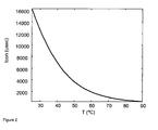
- Figure 2 shows the commutation time transfer function of a leakage inverter with the temperature. The figure has been obtained through computer simulation of a real circuit.
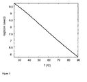
- Figure 3 shows the commutation time transfer function of a leakage inverter with the temperature when the logarithm operation has been applied. The figure has been obtained through computer simulation of a real circuit.
- the present invention is illustrated by means of the electronic circuit of figure 1 , which does not intend to limit its scope.
- the gate width will have to be calculated in such a way that the leakage current value of the p-type device (1) can be reduced from the leakage current of the n-type device (2).
- the capacitor C L (3) When the input signal (9) activates the p-type device (1), the capacitor C L (3) is charged. When the input signal (9) deactivates the p-type device (1), the output terminal of the leakage inverter is floating and the capacitor C L (3) begins to discharge through the n-type device (2). Besides, in the moment the input signal (9) deactivates the p-type device (1), the control signal (8) activates the logarithmic counter and its count begins. When, due to the discharge process, the terminal voltage of the capacitor C L (3) is lower than the inverter (4), the logarithmic counter receives a pulse at its input and stops the count. The count of the logarithmic counter provides the output of the circuit (10).
Landscapes
- Engineering & Computer Science (AREA)
- General Engineering & Computer Science (AREA)
- Physics & Mathematics (AREA)
- General Physics & Mathematics (AREA)
- Testing Of Individual Semiconductor Devices (AREA)
- Semiconductor Integrated Circuits (AREA)
Applications Claiming Priority (2)
| Application Number | Priority Date | Filing Date | Title |
|---|---|---|---|
| ES200702109A ES2291143B2 (es) | 2007-07-27 | 2007-07-27 | Aparato para la medida de temperatura y corriente de fugas en un chip. |
| PCT/ES2008/000478 WO2009022038A1 (es) | 2007-07-27 | 2008-07-07 | Aparato para la medida de temperatura y corriente de fugas en un chip. |
Publications (2)
| Publication Number | Publication Date |
|---|---|
| EP2175288A1 true EP2175288A1 (de) | 2010-04-14 |
| EP2175288A4 EP2175288A4 (de) | 2013-03-13 |
Family
ID=39031190
Family Applications (1)
| Application Number | Title | Priority Date | Filing Date |
|---|---|---|---|
| EP08805308A Withdrawn EP2175288A4 (de) | 2007-07-27 | 2008-07-07 | Vorrichtung zur messung von chip-leckagefluss und -temperatur |
Country Status (4)
| Country | Link |
|---|---|
| US (1) | US20100274505A1 (de) |
| EP (1) | EP2175288A4 (de) |
| ES (1) | ES2291143B2 (de) |
| WO (1) | WO2009022038A1 (de) |
Families Citing this family (3)
| Publication number | Priority date | Publication date | Assignee | Title |
|---|---|---|---|---|
| US10031180B2 (en) | 2015-07-22 | 2018-07-24 | International Business Machines Corporation | Leakage power characterization at high temperatures for an integrated circuit |
| US20180367881A1 (en) * | 2017-06-15 | 2018-12-20 | Apple Inc. | Dual Battery Smart Charge Sharing |
| CN121139547B (zh) * | 2025-10-29 | 2026-02-13 | 北京东方启晨智能装备制造有限公司 | 一种电液伺服阀测试试验台及其测试试验方法 |
Family Cites Families (5)
| Publication number | Priority date | Publication date | Assignee | Title |
|---|---|---|---|---|
| GB999933A (en) * | 1963-08-09 | 1965-07-28 | Cossor Ltd A C | Logarithmic counter |
| JPS52136557A (en) * | 1976-05-11 | 1977-11-15 | Oki Electric Ind Co Ltd | Logarithm counter circuit device |
| US6882172B1 (en) * | 2002-04-16 | 2005-04-19 | Transmeta Corporation | System and method for measuring transistor leakage current with a ring oscillator |
| US7193427B2 (en) * | 2003-06-30 | 2007-03-20 | Intel Corporation | Method and apparatus for measuring relative, within-die leakage current and/or providing a temperature variation profile using a leakage inverter and ring oscillator |
| US7592876B2 (en) * | 2005-12-08 | 2009-09-22 | Intel Corporation | Leakage oscillator based aging monitor |
-
2007
- 2007-07-27 ES ES200702109A patent/ES2291143B2/es active Active
-
2008
- 2008-07-07 WO PCT/ES2008/000478 patent/WO2009022038A1/es not_active Ceased
- 2008-07-07 EP EP08805308A patent/EP2175288A4/de not_active Withdrawn
- 2008-07-07 US US12/670,514 patent/US20100274505A1/en not_active Abandoned
Also Published As
| Publication number | Publication date |
|---|---|
| WO2009022038A1 (es) | 2009-02-19 |
| EP2175288A4 (de) | 2013-03-13 |
| ES2291143A1 (es) | 2008-02-16 |
| US20100274505A1 (en) | 2010-10-28 |
| ES2291143B2 (es) | 2008-07-16 |
Similar Documents
| Publication | Publication Date | Title |
|---|---|---|
| Croon et al. | An easy-to-use mismatch model for the MOS transistor | |
| Karl et al. | Compact in-situ sensors for monitoring negative-bias-temperature-instability effect and oxide degradation | |
| CN101292156B (zh) | 包括离子敏感场效应晶体管的信号处理电路以及监控流体属性的方法 | |
| Bazigos et al. | An adjusted constant-current method to determine saturated and linear mode threshold voltage of MOSFETs | |
| Makie-Fukuda et al. | Measurement of digital noise in mixed-signal integrated circuits | |
| Wang | Automatic V/sub T/extractors based on an n* n/sup 2/MOS transistor array and their application | |
| EP2175288A1 (de) | Vorrichtung zur messung von chip-leckagefluss und -temperatur | |
| CN101621018B (zh) | 一种mosfet频率特性偏差检测器及检测方法 | |
| US6549029B1 (en) | Circuit and method for measuring capacitance | |
| Zhang et al. | A 700nW Compact Temperature Sensor With a One-Point Trimmed Inaccuracy of+ 1.2/− 1.0° C for On-Chip Thermal Monitoring | |
| US7411409B2 (en) | Digital leakage detector that detects transistor leakage current in an integrated circuit | |
| US7118274B2 (en) | Method and reference circuit for bias current switching for implementing an integrated temperature sensor | |
| US20170234816A1 (en) | Temperature sensor based on direct threshold-voltage sensing for on-chip dense thermal monitoring | |
| Deen et al. | A new method for measuring the threshold voltage of small-geometry MOSFETs from subthreshold conduction | |
| CN115659887B (zh) | 一种低电压标准逻辑单元门延时模型的建立方法 | |
| CN116337255B (zh) | 一种基于mos管的超小面积片上智能温度传感器及设计方法 | |
| Paulos et al. | Measurement of minimum-geometry MOS transistor capacitances | |
| Nagy et al. | Design and performance analysis of ultra-low voltage rail-to-rail comparator in 130 nm CMOS technology | |
| Aslanzadeh et al. | ISFET digital readout circuit with an on-chip MIPS processor | |
| Jain et al. | On-chip threshold voltage variability detector targeting supply of ring oscillator for characterizing local device mismatch | |
| Lyu et al. | On-chip process variation sensor based on sub-threshold leakage current with weak bias voltages | |
| Kogut et al. | Simulation of Sensor Capacitive Elements Built into the Microsystem-On-Chip | |
| US12352807B2 (en) | Ultra-compact and micropower circuit to monitor process, voltage, and temperature with high accuracy | |
| US9111894B2 (en) | MOFSET mismatch characterization circuit | |
| US20070263472A1 (en) | Process environment variation evaluation |
Legal Events
| Date | Code | Title | Description |
|---|---|---|---|
| PUAI | Public reference made under article 153(3) epc to a published international application that has entered the european phase |
Free format text: ORIGINAL CODE: 0009012 |
|
| 17P | Request for examination filed |
Effective date: 20091127 |
|
| AK | Designated contracting states |
Kind code of ref document: A1 Designated state(s): AT BE BG CH CY CZ DE DK EE ES FI FR GB GR HR HU IE IS IT LI LT LU LV MC MT NL NO PL PT RO SE SI SK TR |
|
| AX | Request for extension of the european patent |
Extension state: AL BA MK RS |
|
| DAX | Request for extension of the european patent (deleted) | ||
| A4 | Supplementary search report drawn up and despatched |
Effective date: 20130208 |
|
| RIC1 | Information provided on ipc code assigned before grant |
Ipc: G01R 31/30 20060101AFI20130204BHEP |
|
| STAA | Information on the status of an ep patent application or granted ep patent |
Free format text: STATUS: THE APPLICATION IS DEEMED TO BE WITHDRAWN |
|
| 18D | Application deemed to be withdrawn |
Effective date: 20130910 |