EP2175133B1 - Lager mit alternativem Belastungspfad für extreme Lasten - Google Patents
Lager mit alternativem Belastungspfad für extreme Lasten Download PDFInfo
- Publication number
- EP2175133B1 EP2175133B1 EP09172035.9A EP09172035A EP2175133B1 EP 2175133 B1 EP2175133 B1 EP 2175133B1 EP 09172035 A EP09172035 A EP 09172035A EP 2175133 B1 EP2175133 B1 EP 2175133B1
- Authority
- EP
- European Patent Office
- Prior art keywords
- bearing
- race
- load path
- loads
- rolling elements
- Prior art date
- Legal status (The legal status is an assumption and is not a legal conclusion. Google has not performed a legal analysis and makes no representation as to the accuracy of the status listed.)
- Active
Links
Images


Classifications
-
- F—MECHANICAL ENGINEERING; LIGHTING; HEATING; WEAPONS; BLASTING
- F16—ENGINEERING ELEMENTS AND UNITS; GENERAL MEASURES FOR PRODUCING AND MAINTAINING EFFECTIVE FUNCTIONING OF MACHINES OR INSTALLATIONS; THERMAL INSULATION IN GENERAL
- F16C—SHAFTS; FLEXIBLE SHAFTS; ELEMENTS OR CRANKSHAFT MECHANISMS; ROTARY BODIES OTHER THAN GEARING ELEMENTS; BEARINGS
- F16C19/00—Bearings with rolling contact, for exclusively rotary movement
- F16C19/52—Bearings with rolling contact, for exclusively rotary movement with devices affected by abnormal or undesired conditions
- F16C19/522—Bearings with rolling contact, for exclusively rotary movement with devices affected by abnormal or undesired conditions related to load on the bearing, e.g. bearings with load sensors or means to protect the bearing against overload
-
- F—MECHANICAL ENGINEERING; LIGHTING; HEATING; WEAPONS; BLASTING
- F03—MACHINES OR ENGINES FOR LIQUIDS; WIND, SPRING, OR WEIGHT MOTORS; PRODUCING MECHANICAL POWER OR A REACTIVE PROPULSIVE THRUST, NOT OTHERWISE PROVIDED FOR
- F03D—WIND MOTORS
- F03D80/00—Details, components or accessories not provided for in groups F03D1/00 - F03D17/00
- F03D80/70—Bearing or lubricating arrangements
-
- F—MECHANICAL ENGINEERING; LIGHTING; HEATING; WEAPONS; BLASTING
- F16—ENGINEERING ELEMENTS AND UNITS; GENERAL MEASURES FOR PRODUCING AND MAINTAINING EFFECTIVE FUNCTIONING OF MACHINES OR INSTALLATIONS; THERMAL INSULATION IN GENERAL
- F16C—SHAFTS; FLEXIBLE SHAFTS; ELEMENTS OR CRANKSHAFT MECHANISMS; ROTARY BODIES OTHER THAN GEARING ELEMENTS; BEARINGS
- F16C19/00—Bearings with rolling contact, for exclusively rotary movement
- F16C19/02—Bearings with rolling contact, for exclusively rotary movement with bearing balls essentially of the same size in one or more circular rows
- F16C19/10—Bearings with rolling contact, for exclusively rotary movement with bearing balls essentially of the same size in one or more circular rows for axial load mainly
-
- F—MECHANICAL ENGINEERING; LIGHTING; HEATING; WEAPONS; BLASTING
- F16—ENGINEERING ELEMENTS AND UNITS; GENERAL MEASURES FOR PRODUCING AND MAINTAINING EFFECTIVE FUNCTIONING OF MACHINES OR INSTALLATIONS; THERMAL INSULATION IN GENERAL
- F16C—SHAFTS; FLEXIBLE SHAFTS; ELEMENTS OR CRANKSHAFT MECHANISMS; ROTARY BODIES OTHER THAN GEARING ELEMENTS; BEARINGS
- F16C19/00—Bearings with rolling contact, for exclusively rotary movement
- F16C19/02—Bearings with rolling contact, for exclusively rotary movement with bearing balls essentially of the same size in one or more circular rows
- F16C19/14—Bearings with rolling contact, for exclusively rotary movement with bearing balls essentially of the same size in one or more circular rows for both radial and axial load
- F16C19/16—Bearings with rolling contact, for exclusively rotary movement with bearing balls essentially of the same size in one or more circular rows for both radial and axial load with a single row of balls
- F16C19/163—Bearings with rolling contact, for exclusively rotary movement with bearing balls essentially of the same size in one or more circular rows for both radial and axial load with a single row of balls with angular contact
-
- F—MECHANICAL ENGINEERING; LIGHTING; HEATING; WEAPONS; BLASTING
- F16—ENGINEERING ELEMENTS AND UNITS; GENERAL MEASURES FOR PRODUCING AND MAINTAINING EFFECTIVE FUNCTIONING OF MACHINES OR INSTALLATIONS; THERMAL INSULATION IN GENERAL
- F16C—SHAFTS; FLEXIBLE SHAFTS; ELEMENTS OR CRANKSHAFT MECHANISMS; ROTARY BODIES OTHER THAN GEARING ELEMENTS; BEARINGS
- F16C21/00—Combinations of sliding-contact bearings with ball or roller bearings, for exclusively rotary movement
-
- F—MECHANICAL ENGINEERING; LIGHTING; HEATING; WEAPONS; BLASTING
- F16—ENGINEERING ELEMENTS AND UNITS; GENERAL MEASURES FOR PRODUCING AND MAINTAINING EFFECTIVE FUNCTIONING OF MACHINES OR INSTALLATIONS; THERMAL INSULATION IN GENERAL
- F16C—SHAFTS; FLEXIBLE SHAFTS; ELEMENTS OR CRANKSHAFT MECHANISMS; ROTARY BODIES OTHER THAN GEARING ELEMENTS; BEARINGS
- F16C33/00—Parts of bearings; Special methods for making bearings or parts thereof
- F16C33/30—Parts of ball or roller bearings
- F16C33/38—Ball cages
- F16C33/3806—Details of interaction of cage and race, e.g. retention, centring
-
- F—MECHANICAL ENGINEERING; LIGHTING; HEATING; WEAPONS; BLASTING
- F16—ENGINEERING ELEMENTS AND UNITS; GENERAL MEASURES FOR PRODUCING AND MAINTAINING EFFECTIVE FUNCTIONING OF MACHINES OR INSTALLATIONS; THERMAL INSULATION IN GENERAL
- F16C—SHAFTS; FLEXIBLE SHAFTS; ELEMENTS OR CRANKSHAFT MECHANISMS; ROTARY BODIES OTHER THAN GEARING ELEMENTS; BEARINGS
- F16C33/00—Parts of bearings; Special methods for making bearings or parts thereof
- F16C33/30—Parts of ball or roller bearings
- F16C33/38—Ball cages
- F16C33/3837—Massive or moulded cages having cage pockets surrounding the balls, e.g. machined window cages
-
- F—MECHANICAL ENGINEERING; LIGHTING; HEATING; WEAPONS; BLASTING
- F16—ENGINEERING ELEMENTS AND UNITS; GENERAL MEASURES FOR PRODUCING AND MAINTAINING EFFECTIVE FUNCTIONING OF MACHINES OR INSTALLATIONS; THERMAL INSULATION IN GENERAL
- F16C—SHAFTS; FLEXIBLE SHAFTS; ELEMENTS OR CRANKSHAFT MECHANISMS; ROTARY BODIES OTHER THAN GEARING ELEMENTS; BEARINGS
- F16C39/00—Relieving load on bearings
- F16C39/02—Relieving load on bearings using mechanical means
-
- F—MECHANICAL ENGINEERING; LIGHTING; HEATING; WEAPONS; BLASTING
- F05—INDEXING SCHEMES RELATING TO ENGINES OR PUMPS IN VARIOUS SUBCLASSES OF CLASSES F01-F04
- F05B—INDEXING SCHEME RELATING TO WIND, SPRING, WEIGHT, INERTIA OR LIKE MOTORS, TO MACHINES OR ENGINES FOR LIQUIDS COVERED BY SUBCLASSES F03B, F03D AND F03G
- F05B2240/00—Components
- F05B2240/50—Bearings
-
- F—MECHANICAL ENGINEERING; LIGHTING; HEATING; WEAPONS; BLASTING
- F16—ENGINEERING ELEMENTS AND UNITS; GENERAL MEASURES FOR PRODUCING AND MAINTAINING EFFECTIVE FUNCTIONING OF MACHINES OR INSTALLATIONS; THERMAL INSULATION IN GENERAL
- F16C—SHAFTS; FLEXIBLE SHAFTS; ELEMENTS OR CRANKSHAFT MECHANISMS; ROTARY BODIES OTHER THAN GEARING ELEMENTS; BEARINGS
- F16C19/00—Bearings with rolling contact, for exclusively rotary movement
- F16C19/02—Bearings with rolling contact, for exclusively rotary movement with bearing balls essentially of the same size in one or more circular rows
- F16C19/14—Bearings with rolling contact, for exclusively rotary movement with bearing balls essentially of the same size in one or more circular rows for both radial and axial load
- F16C19/18—Bearings with rolling contact, for exclusively rotary movement with bearing balls essentially of the same size in one or more circular rows for both radial and axial load with two or more rows of balls
- F16C19/188—Bearings with rolling contact, for exclusively rotary movement with bearing balls essentially of the same size in one or more circular rows for both radial and axial load with two or more rows of balls with at least one row for radial load in combination with at least one row for axial load
-
- F—MECHANICAL ENGINEERING; LIGHTING; HEATING; WEAPONS; BLASTING
- F16—ENGINEERING ELEMENTS AND UNITS; GENERAL MEASURES FOR PRODUCING AND MAINTAINING EFFECTIVE FUNCTIONING OF MACHINES OR INSTALLATIONS; THERMAL INSULATION IN GENERAL
- F16C—SHAFTS; FLEXIBLE SHAFTS; ELEMENTS OR CRANKSHAFT MECHANISMS; ROTARY BODIES OTHER THAN GEARING ELEMENTS; BEARINGS
- F16C2300/00—Application independent of particular apparatuses
- F16C2300/10—Application independent of particular apparatuses related to size
- F16C2300/14—Large applications, e.g. bearings having an inner diameter exceeding 500 mm
-
- F—MECHANICAL ENGINEERING; LIGHTING; HEATING; WEAPONS; BLASTING
- F16—ENGINEERING ELEMENTS AND UNITS; GENERAL MEASURES FOR PRODUCING AND MAINTAINING EFFECTIVE FUNCTIONING OF MACHINES OR INSTALLATIONS; THERMAL INSULATION IN GENERAL
- F16C—SHAFTS; FLEXIBLE SHAFTS; ELEMENTS OR CRANKSHAFT MECHANISMS; ROTARY BODIES OTHER THAN GEARING ELEMENTS; BEARINGS
- F16C2360/00—Engines or pumps
- F16C2360/31—Wind motors
-
- F—MECHANICAL ENGINEERING; LIGHTING; HEATING; WEAPONS; BLASTING
- F16—ENGINEERING ELEMENTS AND UNITS; GENERAL MEASURES FOR PRODUCING AND MAINTAINING EFFECTIVE FUNCTIONING OF MACHINES OR INSTALLATIONS; THERMAL INSULATION IN GENERAL
- F16C—SHAFTS; FLEXIBLE SHAFTS; ELEMENTS OR CRANKSHAFT MECHANISMS; ROTARY BODIES OTHER THAN GEARING ELEMENTS; BEARINGS
- F16C33/00—Parts of bearings; Special methods for making bearings or parts thereof
- F16C33/30—Parts of ball or roller bearings
- F16C33/37—Loose spacing bodies
- F16C33/3706—Loose spacing bodies with concave surfaces conforming to the shape of the rolling elements, e.g. the spacing bodies are in sliding contact with the rolling elements
-
- Y—GENERAL TAGGING OF NEW TECHNOLOGICAL DEVELOPMENTS; GENERAL TAGGING OF CROSS-SECTIONAL TECHNOLOGIES SPANNING OVER SEVERAL SECTIONS OF THE IPC; TECHNICAL SUBJECTS COVERED BY FORMER USPC CROSS-REFERENCE ART COLLECTIONS [XRACs] AND DIGESTS
- Y02—TECHNOLOGIES OR APPLICATIONS FOR MITIGATION OR ADAPTATION AGAINST CLIMATE CHANGE
- Y02E—REDUCTION OF GREENHOUSE GAS [GHG] EMISSIONS, RELATED TO ENERGY GENERATION, TRANSMISSION OR DISTRIBUTION
- Y02E10/00—Energy generation through renewable energy sources
- Y02E10/70—Wind energy
- Y02E10/72—Wind turbines with rotation axis in wind direction
Definitions
- This invention relates generally to rolling element bearings having an alternative load path for extreme loads.
- a wind turbine includes a rotor having multiple blades.
- the rotor is mounted to a housing or nacelle, which is positioned on top of a truss or tubular tower.
- Utility grade wind turbines i.e., wind turbines designed to provide electrical power to a utility grid
- the gearbox steps up the inherently low rotational speed of the turbine rotor for the generator to efficiently convert mechanical energy to electrical energy, which is fed into a utility grid.
- Wind turbines including direct drive generators eliminate the gearbox, and reliability problems associated with the gearboxes.
- rotor bearings, pitch bearings, generator bearings and other bearings may prematurely fail. Because the bearings can be difficult to access and replace, failure of bearings can result in a lengthy and expensive repair process.
- bearing replacement and/or repair should be performed rapidly at the wind turbine site with a minimal infrastructure and skill set required.
- known bearings used in wind turbines generally require change-out at the factory or labor intensive and costly on-site repair.
- a roller bearing is provided to support a turret of an armoured vehicle.
- Elastic rollers are provided to support the turret.
- a small gap is provided between the collars.
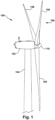
- a wind turbine 100 comprises a nacelle 102 housing a generator (not shown in Figure 1 ). Nacelle 102 is mounted atop a tall tower 104, only a portion of which is shown in Figure 1 .
- Wind turbine 100 also comprises a rotor 106 that includes one or more rotor blades 108 attached to a rotating hub 110.
- wind turbine 100 illustrated in Figure 1 includes three rotor blades 108, there are no specific limits on the number of rotor blades 108.
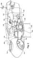
- various components are housed in nacelle 102 atop tower 104 of wind turbine 100.
- the height of tower 104 is selected based upon factors and conditions known in the art.
- one or more microcontrollers within control panel 112 comprise a control system used for overall system monitoring and control.
- Alternative distributed or centralized control architectures are used in some configurations.
- a variable blade pitch drive 114 is provided to control the pitch of blades 108 (not shown in Figure 2 ) that drive hub 110 as a result of wind.
- the pitch angles of blades 108 are individually controlled by blade pitch drive 114.
- Hub 110 and blades 108 together comprise wind turbine rotor 106.
- the drive train of the wind turbine includes a main rotor shaft 116 (also referred to as a "low speed shaft”) connected to hub 110 via main bearing 130 and (in some configurations), at an opposite end of shaft 116 to a gear box 118.
- Gearbox 118 drives a high-speed shaft of generator 120.
- main rotor shaft 116 is coupled directly to generator 120.
- the high-speed shaft (not identified in Figure 2 ) is used to drive generator 120, which is mounted on mainframe 132.
- rotor torque is transmitted via coupling 122.
- generator 120 is a direct drive permanent magnet generator.
- Yaw drive 124 and yaw deck 126 provide a yaw orientation system for wind turbine 100.
- a meteorological boom 128 provides information for a turbine control system, which may include wind direction and/or wind speed.
- the yaw system is mounted on a flange provided atop tower 104.
- Fig. 3 illustrates one known bearing of the double row type. Bearings of this type can be used in the pitch or yaw system of wind turbines. This configuration is typically chosen to compensate for high loads that occur infrequently.
- the bearing 310 is located at the junction between tower 104 and the nacelle's bedplate or mainframe 132.
- the wind turbine 100 can be subject to occasional heavy gusts of wind. These gusts are typically of short duration, however they do exert extreme loads on the wind turbine.
- the wind can force the nacelle to tilt against one side of bearing 310. This force is transmitted from the main frame 132 through the yaw bearing 310 into tower 104.
- the double row bearing 310 has the advantage of being able to bear higher loads than known single row bearings, however, the cost of double row bearings is much greater.
- FIG. 4 Another variation of a known double row bearing is shown in Fig. 4 .
- a portion of the inner raceway 405 extends between the bearings.
- the outer raceway 415 "wraps" around the bearings and the inner raceway extension.
- the load experienced between the races is transmitted through the rolling elements (e.g., balls).
- the use of a double or triple row bearing has been required. It would be advantageous if a lower cost, single row bearing could be designed to accommodate high loads as well.
- Fig. 5 illustrates a bearing according to the present invention.
- the bearing 500 can be used as the pitch bearing or yaw bearing in wind turbine 100.
- the inner race 505 includes a shoulder 506, and the outer race 515 contains a shoulder 516.
- the rolling elements are balls 510 located between the inner race 505 and outer race
- the rolling elements could be rollers, e.g. tapered, barrel shaped or cylindrical rollers.
- the solid arrows 520 indicate the load path from the outer race 515 to the inner race 505 during normal or no load conditions. As can be seen, the load is transmitted from the outer race 515 through balls 510 to the inner race 505. In such state, the bearing has a low friction torque typical for the bearing type. During extreme loading conditions the load path is changed to pass from outer race 515 directly to inner race 505, substantially bypassing bearing 510.
- Wind turbine components are generally designed for two major criteria “extreme” and “normal” wind loads. Normal loads can be determined where there is a mean and some fluctuation around it. This produces “useful” power, and components are initially designed (screened) for fatigue and cumulative damage against this repetitive loading. In addition, components are also designed for extreme loads.
- extreme loads in the wind turbine field is defined as the 50-Year Gust (e.g., Ve50). Components have to withstand this "one time” each 50 years. For example, the 50-Year Gust could be the highest expected velocity of wind expected over a fifty year time period. Fatigue (i.e., repetitive loads) is not necessarily a criterion in this case. Different design rules can be used to address extreme loading scenarios, for example, that the ultimate tensile stress in the material should not be exceeded.
- Ve50 the largest wind speed to be considered is called "Ve50", which is the maximum gust over a 50-year return period for a 3-second averaging time. Extreme loads can occur during a Ve50 situation. When extreme loads occur the alternate or extreme load path, according to the present invention, is utilized to support them at least partially.
- extreme load can be defined as any load in excess of normal operating load or any load that puts a large amount of stress on bearing 500.
- extreme loads can be caused by gusts of wind and/or wind speeds greater than the rated wind speed or cutout wind speed, or during a Ve50 situation.
- the shoulders 506 and 516 of the inner and outer race are not in contact during normal operating conditions. However, during extreme loading conditions the inner 506 and outer 516 shoulders make contact with each other and effectively protect bearing 510 from excess deformation and/or damage.
- the dashed arrows 530 illustrate the load path during extreme loading.
- the blade of a wind turbine could be attached to the outer race 515 and the hub could be attached to the inner race 505.
- the nacelle bedplate could be attached to inner race 505 and the tower could be attached to outer race 515.
- Figs. 6 and 7 illustrate another embodiment of the present invention, in which the alternate load path for extreme loads makes use of other bearing hardware.
- the bearing spacing elements 750 can be manufactured with an outer diameter slightly smaller than the bearing's 610 diameter.
- the load path 620 is from the outer race 615 through the balls 610 to inner race 605.
- the inner and outer races are forced closer to each other, and the spacing elements 750 become part of the extreme load path.
- the extreme load path 630 is from the outer race 615, through the bearing spacing elements 750 to inner race 610. In this manner, the balls 610 can be protected from damage due to extreme loads.
- Figs. 8 and 9 illustrate another embodiment of the present invention.
- the cage In bearings with a cage, the cage can become a load-carrying member during extreme loads.
- the cage 850 functions in similar fashion as the bearing spacing elements of Figs. 6 and 7 .
- the balls 810 are at least partially contained within cage 850, and both balls 810 and cage 850 are placed between the inner race 805 and outer race 815.
- the load path 820 is from the outer race 815 through balls 810 to inner race 805.
- the alternate load path 830 is from the outer race 815 through cage 850 to inner race 805,
- the cage 850 can be comprised of a plurality of spacing elements connected together via one or more circumferential rings.
- Shoulder 806 can be placed on the inner race 805 (as shown) and/or on the outer race 815. The shoulder can be placed above and/or below the cage 850 as well.
- Fig. 10 illustrates another embodiment of the present invention, which is an improvement to the type of bearing illustrated in Fig. 4 .
- Inner race 1005 incorporates a pocket 1006.
- Outer race 1015 includes a projection 1016, which extends at least partially into pocket 1006.
- Two series of balls 1010 are placed above and below projection 1016. During normal loads, the load path is from the outer race 1015 and projection 1016 through balls 1010 to inner race 1005. During extreme loads, the alternate load path is from the outer race 1015, projection 1016 through pocket 1006 to inner race 1005.
- Test data was obtained on a 1.5 MW wind turbine, and the pitch bearing showed a deflection of about 0.7 mm to about 1.0 mm at extreme loads. Operating loads were in the range of about 1,200 kNm or less. As one example only, if the shoulders were spaced about 0.45 mm from each other, then the load on the balls and raceway system (i.e., the pitch bearing) would be reduced by about half. It is to be understood that the shoulders could be spaced from each other by more or less than the amount in the previous example, and the spacing is determined by the requirements of the specific application.
- the incorporation of alternate load paths for extreme loads in a bearing has many advantages.
- the size of the bearing can be reduced, and this translates into lower cost and reduced weight.
- Towers must support heavy loads, and reducing weight at the top of the tower or in the nacelle is highly beneficial.
- the bearing can also sustain extreme loads with a reduced rate of failure. Bearings that last longer save in maintenance and replacement costs, as well in avoidance of downtime for the wind turbine.
- the shoulders referred to in the description above are preferably enclosed within the lubricated zones of the bearing. In this way a clean contact is provided, preventing dirt to clog the narrow gap. When designed so, a shoulder contact can also be created outside the lubricated zone, accepting possible dirt clogging the gap and interacting during the higher operating loads.
- a double seal system may be applied where the first and inner set of seals keeps the lubricant in and a second set of seals keeps the dirt out.
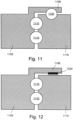
- Fig. 11 illustrates another embodiment of the present invention, which incorporates an additional series of rolling elements.
- a first race 1105 incorporates an extension 1106.
- Rolling elements 1110 are placed between the first race 1105 and the second race 1115.
- An additional series of rolling elements 1120 are placed between the first race extension 1106 and the second race 1115.
- the rolling elements are designed so, that during normal operating load conditions, no load is transferred from extension 1106 through rolling elements 1120 to second race 1115.
- the rolling elements 1120 are slightly undersized with respect to the cooperating races; a cage or spacing element could be incorporated as well.
- the rolling elements 1120 are balls. In other embodiments the rolling elements could be rollers, e.g. tapered, barrel shaped or cylindrical rollers.
- Fig. 12 illustrates another embodiment of the present invention, which incorporates a ribbon or spring 1220 (e.g., a ripple spring).
- spring 1220 could be a thin metallic material formed into a "ribbon" or stamped into a wavy pattern.
- the thin metallic material could be a metal alloy such as a nickel-steel alloy.
- the "ribbon" or spring 1220 could have a non-linear load-deflection curve, which is soft at first, but then would provide a very high reaction after deflecting to a flatter configuration.
- the spring 1220 could be placed on extension 1106 and, if desired (but not required), a low friction material could be placed on an opposing surface.
- spring 1220 is designed to not contact second race 1115 during normal loads, so that no load is normally transferred from extension 1106 through spring 1220 to second race 1115. It is to be understood that spring 1220 could be attached to the extension 1106 and/or the second race 1115.
- the spring 1220 could also be made from one or more of metallic, sintered metallic, plastics, and reinforced plastic material.
- the alternate load path may also comprise layers of lubricating material or a low friction material (e.g., Teflon ® , a registered trademark of E. I. du Pont de Nemours and Company) on one or both of the load bearing surfaces.
- a low friction material e.g., Teflon ® , a registered trademark of E. I. du Pont de Nemours and Company
- One or more load-bearing surface (during extreme loads) may also have material formed into specific shapes to help absorb the extreme loads.
- the sliding or rolling elements of the bearing may also be chosen from one or more of metallic, sintered metallic, plastics, reinforced plastic material.
- the first load path has low friction, low load carrying capacity and a first stiffness level
- the alternate, second load path could have higher friction, higher load carrying capacity and has a greater stiffness level (as compared to the first load path).
- the higher stiffness in the second load path could be obtained by having a shape or material difference between the two load paths.
- the second load path could include a low friction coating and/or a rippled material.
Landscapes
- Engineering & Computer Science (AREA)
- General Engineering & Computer Science (AREA)
- Mechanical Engineering (AREA)
- Life Sciences & Earth Sciences (AREA)
- Sustainable Development (AREA)
- Sustainable Energy (AREA)
- Chemical & Material Sciences (AREA)
- Combustion & Propulsion (AREA)
- Rolling Contact Bearings (AREA)
- Wind Motors (AREA)
Claims (7)
- Lager (500) mit einem ersten Laufring (505, 605, 805, 1005, 1105), einem zweiten Laufring (515, 615, 815, 1015, 1115) und Wälzkörpern (510, 610, 810, 1010, 1110), wobei das Lager (500) ein Pitchlager oder ein Gierlager für eine Windturbine ist, wobei das Lager (500) umfasst:einen Lastpfad (520, 620, 820) für normale Lasten, wobei der Lastpfad für normale Lasten (520, 620, 820) die Last von dem ersten Laufring (505, 605, 805, 1005, 1105) durch die Wälzkörper (510, 610, 810, 1010, 1110) auf den zweiten Laufring (515) überträgt; undeinen alternativen Belastungspfad (530) für extreme Belastungen, wobei der alternative Belastungspfad zwischen dem ersten Laufring (505, 605, 805, 1005, 1105) und dem zweiten Laufring (515, 615, 815, 1015, 1115) ausgebildet ist und eine höhere Steifigkeit aufweist, wobei der alternative Belastungspfad (530, 630, 830) während normaler Lastbedingungen keine Last überträgt und während extremer Lastbedingungen zumindest einen Teil der extremen Lasten von den Wälzkörpern (510, 610, 810, 1010, 1110) ableitet.
- Lager (500) nach Anspruch 1, wobei eine Schulter (506) an dem ersten Laufring (505) ausgebildet ist, wobei die Schulter (506) einen Teil des alternativen Lastpfades (530) bildet.
- Lager (500) nach einem der vorhergehenden Ansprüche, wobei eine Schulter (516) an dem zweiten Laufring (515) ausgebildet ist, wobei die Schulter (516) einen Teil des alternativen Lastpfads (530) bildet.
- Lager nach einem der vorhergehenden Ansprüche, wobei mindestens ein Abstandselement (750, 850) zwischen den Wälzkörpern (610, 810) angeordnet ist, wobei das mindestens eine Abstandselement (750, 850) einen Teil des alternativen Lastpfads (630, 830) bildet.
- Lager nach Anspruch 4, wobei das mindestens eine Abstandselement (850) einen Käfig umfasst, der um mindestens einen Teil der Wälzkörper (810) gebildet ist.
- Lager (500) nach einem der vorhergehenden Ansprüche, wobei die Wälzkörper (510, 610, 810, 1010, 1110) aus mindestens einer der folgenden Gruppen ausgewählt sind:
Kugeln, Rollen, kegelförmige Rollen, tonnenförmige Rollen und zylindrische Rollen. - Lager nach einem der vorhergehenden Ansprüche, ferner umfassend:mindestens einen Hohlraum (1006), der in dem ersten Laufring (1005) ausgebildet ist; undmindestens einen Vorsprung (1016), der an dem zweiten Laufring (1015) ausgebildet ist, wobei sich der mindestens eine Vorsprung (1016) zumindest teilweise in den mindestens einen Hohlraum (1006) erstreckt,wobei der alternative Lastpfad für extreme Lasten zwischen dem ersten Laufring (1005), dem mindestens einen Vorsprung (1016), dem mindestens einen Hohlraum (1006) und dem zweiten Laufring (1015) gebildet wird.
Applications Claiming Priority (1)
| Application Number | Priority Date | Filing Date | Title |
|---|---|---|---|
| US12/249,003 US8459872B2 (en) | 2008-10-10 | 2008-10-10 | Bearing with alternative load path for extreme loads |
Publications (3)
| Publication Number | Publication Date |
|---|---|
| EP2175133A2 EP2175133A2 (de) | 2010-04-14 |
| EP2175133A3 EP2175133A3 (de) | 2018-02-28 |
| EP2175133B1 true EP2175133B1 (de) | 2024-09-18 |
Family
ID=41572580
Family Applications (1)
| Application Number | Title | Priority Date | Filing Date |
|---|---|---|---|
| EP09172035.9A Active EP2175133B1 (de) | 2008-10-10 | 2009-10-02 | Lager mit alternativem Belastungspfad für extreme Lasten |
Country Status (5)
| Country | Link |
|---|---|
| US (1) | US8459872B2 (de) |
| EP (1) | EP2175133B1 (de) |
| CN (1) | CN101725632B (de) |
| DK (1) | DK2175133T3 (de) |
| ES (1) | ES2996218T3 (de) |
Families Citing this family (32)
| Publication number | Priority date | Publication date | Assignee | Title |
|---|---|---|---|---|
| US20110254281A1 (en) * | 2009-06-16 | 2011-10-20 | Mitsubishi Heavy Industries, Ltd. | Wind turbine generator |
| GB0916189D0 (en) * | 2009-09-15 | 2009-10-28 | Ricardo Uk Ltd | Bearing for wind turbine |
| DK2494191T3 (da) * | 2009-10-29 | 2014-08-11 | Mervento Oy | Vindkraftstation |
| US8174144B2 (en) * | 2010-12-21 | 2012-05-08 | General Electric Company | Bearings having radial half cage |
| ES2542101T3 (es) * | 2011-08-25 | 2015-07-30 | Imo Holding Gmbh | Buje de una instalación de energía eólica para la regulación de varios elementos relativamente entre sí |
| US8794847B2 (en) * | 2011-09-14 | 2014-08-05 | Aktiebolaget Skf | Bearing assembly with axial retainer |
| US8469664B2 (en) * | 2011-12-09 | 2013-06-25 | General Electric Company | Yaw bearing assembly and tower for wind turbine |
| WO2013107518A1 (en) * | 2012-01-20 | 2013-07-25 | Aktiebolaget Skf | Gear-driven bearing unit |
| US8678655B1 (en) * | 2012-04-11 | 2014-03-25 | The United States Of America As Represented By The Secretary Of The Army | Reinforced slewing bearing |
| EP2679815B1 (de) | 2012-06-26 | 2017-02-01 | ALSTOM Renewable Technologies | Windturbine mit einer Rotationsanordnung |
| EP2679816B1 (de) | 2012-06-27 | 2015-08-19 | ALSTOM Renewable Technologies | Anstellsystem für einen Windturbinenrotor |
| US9188107B2 (en) * | 2013-08-30 | 2015-11-17 | General Electric Company | Wind turbine bearings |
| CN103541992B (zh) * | 2013-10-08 | 2016-03-16 | 上海斐赛轴承科技有限公司 | 带凸出量的深沟球轴承、带间隙的轴承对及低温升振动棒 |
| US9494190B2 (en) * | 2015-02-12 | 2016-11-15 | Simmonds Precision Products, Inc | Bearing assembly with overload protection |
| US10364795B2 (en) | 2015-07-03 | 2019-07-30 | Darell Allen Williams | Wind turbine for use in high winds |
| US9777707B2 (en) | 2015-07-03 | 2017-10-03 | Darell Allen Williams | Windmill that generates exceptional amounts of electricity |
| JP2017044268A (ja) * | 2015-08-26 | 2017-03-02 | Thk株式会社 | 旋回軸受 |
| US10598159B2 (en) | 2016-05-06 | 2020-03-24 | General Electric Company | Wind turbine bearings |
| US10100875B2 (en) | 2016-07-26 | 2018-10-16 | General Electric Company | Roller bearing and systems including such |
| US10030708B2 (en) | 2016-07-29 | 2018-07-24 | General Electric Company | Roller bearing cage for use in a gearbox |
| US10138940B2 (en) | 2016-08-09 | 2018-11-27 | General Electric Company | Roller bearing cage for use in a gearbox |
| US10400678B2 (en) | 2017-01-03 | 2019-09-03 | General Electric Company | Apparatus and system for light-weight, flexible double-helical gear |
| US10508731B2 (en) | 2017-01-05 | 2019-12-17 | General Electric Company | Apparatus and method for managing pinch loads on a gear |
| US10247298B2 (en) | 2017-01-10 | 2019-04-02 | General Electric Company | Resilient bearing pin and gear assemblies including resilient bearing pins |
| US10228024B2 (en) | 2017-01-10 | 2019-03-12 | General Electric Company | Reduced-weight bearing pins and methods of manufacturing such bearing pins |
| US10247297B2 (en) | 2017-01-18 | 2019-04-02 | General Electric Company | Apparatus for a gearbox with multiple scavenge ports |
| US10408304B2 (en) | 2017-02-07 | 2019-09-10 | General Electric Company | Gears having reduced roller element stresses and methods of manufacturing such gears |
| US10451113B2 (en) | 2017-05-18 | 2019-10-22 | General Electric Company | Bearing cages for roller bearing assemblies |
| US10260563B2 (en) | 2017-05-18 | 2019-04-16 | General Electric Company | Bearing cages for roller bearing assemblies |
| US10677290B2 (en) * | 2017-10-13 | 2020-06-09 | General Electric Company | Wind turbine pitch bearing with line contact rolling elements |
| US10385961B2 (en) | 2017-10-25 | 2019-08-20 | General Electric Company | Planetary gear system |
| CN108150367B (zh) * | 2017-12-30 | 2020-06-02 | 新疆金风科技股份有限公司 | 偏航轴承组件及风力发电机组 |
Citations (5)
| Publication number | Priority date | Publication date | Assignee | Title |
|---|---|---|---|---|
| DE3725972A1 (de) * | 1987-08-05 | 1989-02-16 | Schaeffler Waelzlager Kg | Waelzlager-drehverbindung |
| DE4322729C1 (de) | 1993-07-08 | 1994-09-01 | Daimler Benz Ag | Drehlageranordnung mit Wälz-Gleitlager-Kombination |
| DE19814629A1 (de) | 1998-03-26 | 1999-09-30 | Tacke Windenergie Gmbh | Anordnung zur drehbaren Lagerung der Maschinengondel einer Windkraftanlage |
| WO2006131301A2 (de) | 2005-06-06 | 2006-12-14 | Imo Holding Gmbh | Lagereinheit für ein langgestrecktes rotorblatt einer windkraftanlage, mit einer solchen rotorblattlagerung ausgestattete windkraftanlage sowie verfahren zum betrieb einer derartigen windkraftanlage |
| DE202007011577U1 (de) | 2006-10-31 | 2007-10-25 | Imo Holding Gmbh | Wälzlageranordnung |
Family Cites Families (28)
| Publication number | Priority date | Publication date | Assignee | Title |
|---|---|---|---|---|
| US1182370A (en) * | 1909-01-06 | 1916-05-09 | Hess Bright Mfg Co | Antifriction-bearing. |
| FR459455A (fr) * | 1913-05-14 | 1913-11-06 | John Cockerill | Dispositif de roulement pour la rotation des coupoles cuirassées, tables tournantes, ponts tournants et appareils similaires |
| US2244197A (en) * | 1936-03-25 | 1941-06-03 | Hessler Christian Rudolph | Bearing |
| GB1342233A (en) * | 1969-11-19 | 1974-01-03 | British Aircraft Corp Ltd | Bearing systems |
| US3814488A (en) * | 1973-03-26 | 1974-06-04 | Keene Corp | Bearing assembly |
| DE7501166U (de) * | 1975-01-17 | 1976-01-08 | Nordisk Ventilator Co. A/S, Naestved (Daenemark) | Axialwaelzlager fuer die lagerung winkelverstellbarer axialgeblaeseschaufeln in der nabe eines schaufelrades |
| JPS55149418A (en) * | 1979-04-28 | 1980-11-20 | Nachi Fujikoshi Corp | Split roller bearing |
| US4906113A (en) | 1988-07-27 | 1990-03-06 | Quintette Coal Limited | Slew ring bearing |
| EP0481632A3 (en) * | 1990-10-19 | 1993-06-09 | Raytheon Company | High force ball bearings |
| US5165804A (en) | 1991-09-03 | 1992-11-24 | General Electric Company | Rolling element bearing having wear resistant race land regions |
| JP3076693B2 (ja) * | 1993-06-04 | 2000-08-14 | 日本トムソン株式会社 | クロスローラベアリング及びその製造方法 |
| US5588754A (en) * | 1995-12-29 | 1996-12-31 | United Technologies Automotive, Inc. | Backup bearings for extreme speed touch down applications |
| US5642944A (en) * | 1996-03-06 | 1997-07-01 | W. L. Dublin, Jr. | Auxiliary bearing system |
| EP0816654B1 (de) * | 1996-06-26 | 2004-09-22 | Rolls-Royce Corporation | Lagerkombination für eine Gasturbine |
| US5957000A (en) | 1998-01-05 | 1999-09-28 | Pecorari; Paul A. | Lubricated worm gear driven slewing bearing |
| JP4099259B2 (ja) * | 1998-03-02 | 2008-06-11 | ミネベア株式会社 | 複合軸受け |
| JP4530554B2 (ja) * | 2001-02-16 | 2010-08-25 | Thk株式会社 | 滑り軸受の製造方法 |
| JP2002339990A (ja) * | 2001-05-22 | 2002-11-27 | Harmonic Drive Syst Ind Co Ltd | 軽量ベアリングおよび波動歯車装置 |
| JP4261339B2 (ja) * | 2001-06-15 | 2009-04-30 | ソシエテ・ドゥ・メカニーク・マグネティーク | 軸荷重の影響を受けない非常用軸受 |
| US7042109B2 (en) * | 2002-08-30 | 2006-05-09 | Gabrys Christopher W | Wind turbine |
| FR2859256B1 (fr) * | 2003-08-27 | 2006-11-24 | Defontaine Sa | Couronne d'orientation |
| DE10344804B4 (de) * | 2003-09-26 | 2006-11-30 | Aktiebolaget Skf | Schwenklagerung |
| US7075192B2 (en) * | 2004-04-19 | 2006-07-11 | Northern Power Systems, Inc. | Direct drive wind turbine |
| FR2887943B1 (fr) * | 2005-07-04 | 2008-08-22 | Defontaine Sa | Palier d'eolienne a transmission d'efforts |
| US7360310B2 (en) * | 2005-10-05 | 2008-04-22 | General Electric Company | Method for changing removable bearing for a wind turbine generator |
| JP4668160B2 (ja) * | 2006-11-09 | 2011-04-13 | 株式会社森精機製作所 | 軸受ユニット及び該軸受ユニットを備えた工作機械の主軸装置 |
| WO2008074322A2 (en) * | 2006-12-18 | 2008-06-26 | Vestas Wind Systems A/S | A bearing and method for transferring forces through a bearing of a wind turbine |
| US8174144B2 (en) * | 2010-12-21 | 2012-05-08 | General Electric Company | Bearings having radial half cage |
-
2008
- 2008-10-10 US US12/249,003 patent/US8459872B2/en active Active
-
2009
- 2009-10-02 EP EP09172035.9A patent/EP2175133B1/de active Active
- 2009-10-02 DK DK09172035.9T patent/DK2175133T3/da active
- 2009-10-02 ES ES09172035T patent/ES2996218T3/es active Active
- 2009-10-09 CN CN200910179490.5A patent/CN101725632B/zh active Active
Patent Citations (5)
| Publication number | Priority date | Publication date | Assignee | Title |
|---|---|---|---|---|
| DE3725972A1 (de) * | 1987-08-05 | 1989-02-16 | Schaeffler Waelzlager Kg | Waelzlager-drehverbindung |
| DE4322729C1 (de) | 1993-07-08 | 1994-09-01 | Daimler Benz Ag | Drehlageranordnung mit Wälz-Gleitlager-Kombination |
| DE19814629A1 (de) | 1998-03-26 | 1999-09-30 | Tacke Windenergie Gmbh | Anordnung zur drehbaren Lagerung der Maschinengondel einer Windkraftanlage |
| WO2006131301A2 (de) | 2005-06-06 | 2006-12-14 | Imo Holding Gmbh | Lagereinheit für ein langgestrecktes rotorblatt einer windkraftanlage, mit einer solchen rotorblattlagerung ausgestattete windkraftanlage sowie verfahren zum betrieb einer derartigen windkraftanlage |
| DE202007011577U1 (de) | 2006-10-31 | 2007-10-25 | Imo Holding Gmbh | Wälzlageranordnung |
Also Published As
| Publication number | Publication date |
|---|---|
| DK2175133T3 (da) | 2025-01-02 |
| ES2996218T3 (en) | 2025-02-12 |
| CN101725632A (zh) | 2010-06-09 |
| EP2175133A3 (de) | 2018-02-28 |
| CN101725632B (zh) | 2014-04-16 |
| EP2175133A2 (de) | 2010-04-14 |
| US8459872B2 (en) | 2013-06-11 |
| US20100092120A1 (en) | 2010-04-15 |
Similar Documents
| Publication | Publication Date | Title |
|---|---|---|
| EP2175133B1 (de) | Lager mit alternativem Belastungspfad für extreme Lasten | |
| KR101161484B1 (ko) | 풍력 발전 장치용의 증속기 및 풍력 발전 장치 | |
| Kim et al. | Yaw Systems for wind turbines–Overview of concepts, current challenges and design methods | |
| EP1745221B1 (de) | Festlageranordnung für windturbinengetriebewelle | |
| CN102207056B (zh) | 风轮机和风轮机的变桨轴承 | |
| US8174144B2 (en) | Bearings having radial half cage | |
| KR102143165B1 (ko) | 풍력 발전 설비-로터 블레이드 및 이를 포함하는 풍력 발전 설비 | |
| CN109072884B (zh) | 包括力矩轴承的风力涡轮机 | |
| KR20190014540A (ko) | 풍력 발전 설비 | |
| EP3662159B1 (de) | Planetenträger eines windturbinengetriebes mit verbessertem schmiermittelweg | |
| EP3428448B1 (de) | Verbundhauptlageranordnung für eine windturbine | |
| EP3586002B1 (de) | Windturbinenhauptrotoranordnung mit integrierter schmierfunktion | |
| CN101892955A (zh) | 修复变桨控制部件的方法和系统 | |
| CN201666356U (zh) | 一种行星轮的润滑装置 | |
| US20120134808A1 (en) | Wind turbine oil lubrication pump | |
| KR20190015754A (ko) | 풍력 발전 설비의 회전 연결부, 로터 블레이드 및 이러한 로터 블레이드를 포함하는 풍력 발전 설비 | |
| US11174895B2 (en) | Bearing for a wind turbine drivetrain having an elastomer support | |
| CA2393963A1 (en) | Wind power plant | |
| WO2007095953A1 (en) | Gearbox for a wind turbine, bearing and method of manufacturing a bearing | |
| JP6155713B2 (ja) | 風力発電装置用の一方向クラッチ及び風力発電装置 | |
| Yagi et al. | Technical trends in wind turbine bearings | |
| US20190383359A1 (en) | Wind turbine with two-stage star compound gear train | |
| US11598317B2 (en) | Yaw bearings for a wind turbine | |
| KR20100080007A (ko) | 회전 하우징을 갖는 풍력발전기용 기어박스 | |
| EP3788256B1 (de) | Rotor für eine windturbine mit pitchlagereinheit |
Legal Events
| Date | Code | Title | Description |
|---|---|---|---|
| PUAI | Public reference made under article 153(3) epc to a published international application that has entered the european phase |
Free format text: ORIGINAL CODE: 0009012 |
|
| AK | Designated contracting states |
Kind code of ref document: A2 Designated state(s): AT BE BG CH CY CZ DE DK EE ES FI FR GB GR HR HU IE IS IT LI LT LU LV MC MK MT NL NO PL PT RO SE SI SK SM TR |
|
| AX | Request for extension of the european patent |
Extension state: AL BA RS |
|
| PUAL | Search report despatched |
Free format text: ORIGINAL CODE: 0009013 |
|
| AK | Designated contracting states |
Kind code of ref document: A3 Designated state(s): AT BE BG CH CY CZ DE DK EE ES FI FR GB GR HR HU IE IS IT LI LT LU LV MC MK MT NL NO PL PT RO SE SI SK SM TR |
|
| AX | Request for extension of the european patent |
Extension state: AL BA RS |
|
| RIC1 | Information provided on ipc code assigned before grant |
Ipc: F16C 19/52 20060101ALI20180119BHEP Ipc: F03D 11/00 00000000ALN20180119BHEP Ipc: F16C 33/38 20060101ALN20180119BHEP Ipc: F16C 21/00 20060101ALN20180119BHEP Ipc: F16C 19/16 20060101ALN20180119BHEP Ipc: F16C 39/02 20060101AFI20180119BHEP Ipc: F16C 19/10 20060101ALN20180119BHEP |
|
| STAA | Information on the status of an ep patent application or granted ep patent |
Free format text: STATUS: REQUEST FOR EXAMINATION WAS MADE |
|
| 17P | Request for examination filed |
Effective date: 20180828 |
|
| RBV | Designated contracting states (corrected) |
Designated state(s): AT BE BG CH CY CZ DE DK EE ES FI FR GB GR HR HU IE IS IT LI LT LU LV MC MK MT NL NO PL PT RO SE SI SK SM TR |
|
| RIC1 | Information provided on ipc code assigned before grant |
Ipc: F03D 11/00 20181130ALN20180119BHEP Ipc: F16C 19/16 20060101ALN20180119BHEP Ipc: F16C 39/02 20060101AFI20180119BHEP Ipc: F16C 21/00 20060101ALN20180119BHEP Ipc: F16C 19/10 20060101ALN20180119BHEP Ipc: F16C 33/38 20060101ALN20180119BHEP Ipc: F16C 19/52 20060101ALI20180119BHEP |
|
| RIC1 | Information provided on ipc code assigned before grant |
Ipc: F16C 19/52 20060101ALI20180119BHEP Ipc: F03D 11/00 20060101ALN20180119BHEP Ipc: F16C 39/02 20060101AFI20180119BHEP Ipc: F16C 21/00 20060101ALN20180119BHEP Ipc: F16C 33/38 20060101ALN20180119BHEP Ipc: F16C 19/16 20060101ALN20180119BHEP Ipc: F16C 19/10 20060101ALN20180119BHEP |
|
| STAA | Information on the status of an ep patent application or granted ep patent |
Free format text: STATUS: EXAMINATION IS IN PROGRESS |
|
| 17Q | First examination report despatched |
Effective date: 20200624 |
|
| P01 | Opt-out of the competence of the unified patent court (upc) registered |
Effective date: 20230530 |
|
| GRAP | Despatch of communication of intention to grant a patent |
Free format text: ORIGINAL CODE: EPIDOSNIGR1 |
|
| STAA | Information on the status of an ep patent application or granted ep patent |
Free format text: STATUS: GRANT OF PATENT IS INTENDED |
|
| RIC1 | Information provided on ipc code assigned before grant |
Ipc: F03D 80/70 20160101ALN20230914BHEP Ipc: F16C 33/38 20060101ALN20230914BHEP Ipc: F16C 33/37 20060101ALN20230914BHEP Ipc: F16C 19/18 20060101ALN20230914BHEP Ipc: F16C 19/16 20060101ALN20230914BHEP Ipc: F16C 19/10 20060101ALN20230914BHEP Ipc: F16C 21/00 20060101ALN20230914BHEP Ipc: F16C 19/52 20060101ALI20230914BHEP Ipc: F16C 39/02 20060101AFI20230914BHEP |
|
| INTG | Intention to grant announced |
Effective date: 20231004 |
|
| RIC1 | Information provided on ipc code assigned before grant |
Ipc: F03D 80/70 20160101ALN20230925BHEP Ipc: F16C 33/38 20060101ALN20230925BHEP Ipc: F16C 33/37 20060101ALN20230925BHEP Ipc: F16C 19/18 20060101ALN20230925BHEP Ipc: F16C 19/16 20060101ALN20230925BHEP Ipc: F16C 19/10 20060101ALN20230925BHEP Ipc: F16C 21/00 20060101ALN20230925BHEP Ipc: F16C 19/52 20060101ALI20230925BHEP Ipc: F16C 39/02 20060101AFI20230925BHEP |
|
| RAP1 | Party data changed (applicant data changed or rights of an application transferred) |
Owner name: GENERAL ELECTRIC RENOVABLES ESPANA, S.L. |
|
| GRAJ | Information related to disapproval of communication of intention to grant by the applicant or resumption of examination proceedings by the epo deleted |
Free format text: ORIGINAL CODE: EPIDOSDIGR1 |
|
| STAA | Information on the status of an ep patent application or granted ep patent |
Free format text: STATUS: EXAMINATION IS IN PROGRESS |
|
| INTC | Intention to grant announced (deleted) | ||
| GRAP | Despatch of communication of intention to grant a patent |
Free format text: ORIGINAL CODE: EPIDOSNIGR1 |
|
| STAA | Information on the status of an ep patent application or granted ep patent |
Free format text: STATUS: GRANT OF PATENT IS INTENDED |
|
| INTG | Intention to grant announced |
Effective date: 20240416 |
|
| GRAS | Grant fee paid |
Free format text: ORIGINAL CODE: EPIDOSNIGR3 |
|
| GRAA | (expected) grant |
Free format text: ORIGINAL CODE: 0009210 |
|
| STAA | Information on the status of an ep patent application or granted ep patent |
Free format text: STATUS: THE PATENT HAS BEEN GRANTED |
|
| AK | Designated contracting states |
Kind code of ref document: B1 Designated state(s): AT BE BG CH CY CZ DE DK EE ES FI FR GB GR HR HU IE IS IT LI LT LU LV MC MK MT NL NO PL PT RO SE SI SK SM TR |
|
| REG | Reference to a national code |
Ref country code: GB Ref legal event code: FG4D |
|
| REG | Reference to a national code |
Ref country code: CH Ref legal event code: EP |
|
| REG | Reference to a national code |
Ref country code: DE Ref legal event code: R096 Ref document number: 602009065360 Country of ref document: DE |
|
| REG | Reference to a national code |
Ref country code: IE Ref legal event code: FG4D |
|
| REG | Reference to a national code |
Ref country code: DK Ref legal event code: T3 Effective date: 20241217 |
|
| REG | Reference to a national code |
Ref country code: LT Ref legal event code: MG9D |
|
| PG25 | Lapsed in a contracting state [announced via postgrant information from national office to epo] |
Ref country code: NO Free format text: LAPSE BECAUSE OF FAILURE TO SUBMIT A TRANSLATION OF THE DESCRIPTION OR TO PAY THE FEE WITHIN THE PRESCRIBED TIME-LIMIT Effective date: 20241218 |
|
| PG25 | Lapsed in a contracting state [announced via postgrant information from national office to epo] |
Ref country code: GR Free format text: LAPSE BECAUSE OF FAILURE TO SUBMIT A TRANSLATION OF THE DESCRIPTION OR TO PAY THE FEE WITHIN THE PRESCRIBED TIME-LIMIT Effective date: 20241219 Ref country code: FI Free format text: LAPSE BECAUSE OF FAILURE TO SUBMIT A TRANSLATION OF THE DESCRIPTION OR TO PAY THE FEE WITHIN THE PRESCRIBED TIME-LIMIT Effective date: 20240918 |
|
| PG25 | Lapsed in a contracting state [announced via postgrant information from national office to epo] |
Ref country code: BG Free format text: LAPSE BECAUSE OF FAILURE TO SUBMIT A TRANSLATION OF THE DESCRIPTION OR TO PAY THE FEE WITHIN THE PRESCRIBED TIME-LIMIT Effective date: 20240918 |
|
| PG25 | Lapsed in a contracting state [announced via postgrant information from national office to epo] |
Ref country code: LV Free format text: LAPSE BECAUSE OF FAILURE TO SUBMIT A TRANSLATION OF THE DESCRIPTION OR TO PAY THE FEE WITHIN THE PRESCRIBED TIME-LIMIT Effective date: 20240918 |
|
| PG25 | Lapsed in a contracting state [announced via postgrant information from national office to epo] |
Ref country code: HR Free format text: LAPSE BECAUSE OF FAILURE TO SUBMIT A TRANSLATION OF THE DESCRIPTION OR TO PAY THE FEE WITHIN THE PRESCRIBED TIME-LIMIT Effective date: 20240918 |
|
| REG | Reference to a national code |
Ref country code: NL Ref legal event code: MP Effective date: 20240918 |
|
| PGFP | Annual fee paid to national office [announced via postgrant information from national office to epo] |
Ref country code: ES Payment date: 20241106 Year of fee payment: 16 |
|
| PG25 | Lapsed in a contracting state [announced via postgrant information from national office to epo] |
Ref country code: NO Free format text: LAPSE BECAUSE OF FAILURE TO SUBMIT A TRANSLATION OF THE DESCRIPTION OR TO PAY THE FEE WITHIN THE PRESCRIBED TIME-LIMIT Effective date: 20241218 Ref country code: LV Free format text: LAPSE BECAUSE OF FAILURE TO SUBMIT A TRANSLATION OF THE DESCRIPTION OR TO PAY THE FEE WITHIN THE PRESCRIBED TIME-LIMIT Effective date: 20240918 Ref country code: HR Free format text: LAPSE BECAUSE OF FAILURE TO SUBMIT A TRANSLATION OF THE DESCRIPTION OR TO PAY THE FEE WITHIN THE PRESCRIBED TIME-LIMIT Effective date: 20240918 Ref country code: GR Free format text: LAPSE BECAUSE OF FAILURE TO SUBMIT A TRANSLATION OF THE DESCRIPTION OR TO PAY THE FEE WITHIN THE PRESCRIBED TIME-LIMIT Effective date: 20241219 Ref country code: FI Free format text: LAPSE BECAUSE OF FAILURE TO SUBMIT A TRANSLATION OF THE DESCRIPTION OR TO PAY THE FEE WITHIN THE PRESCRIBED TIME-LIMIT Effective date: 20240918 Ref country code: BG Free format text: LAPSE BECAUSE OF FAILURE TO SUBMIT A TRANSLATION OF THE DESCRIPTION OR TO PAY THE FEE WITHIN THE PRESCRIBED TIME-LIMIT Effective date: 20240918 |
|
| REG | Reference to a national code |
Ref country code: ES Ref legal event code: FG2A Ref document number: 2996218 Country of ref document: ES Kind code of ref document: T3 Effective date: 20250212 |
|
| REG | Reference to a national code |
Ref country code: AT Ref legal event code: MK05 Ref document number: 1724920 Country of ref document: AT Kind code of ref document: T Effective date: 20240918 |
|
| PG25 | Lapsed in a contracting state [announced via postgrant information from national office to epo] |
Ref country code: NL Free format text: LAPSE BECAUSE OF FAILURE TO SUBMIT A TRANSLATION OF THE DESCRIPTION OR TO PAY THE FEE WITHIN THE PRESCRIBED TIME-LIMIT Effective date: 20240918 |
|
| PG25 | Lapsed in a contracting state [announced via postgrant information from national office to epo] |
Ref country code: IS Free format text: LAPSE BECAUSE OF FAILURE TO SUBMIT A TRANSLATION OF THE DESCRIPTION OR TO PAY THE FEE WITHIN THE PRESCRIBED TIME-LIMIT Effective date: 20250118 Ref country code: PT Free format text: LAPSE BECAUSE OF FAILURE TO SUBMIT A TRANSLATION OF THE DESCRIPTION OR TO PAY THE FEE WITHIN THE PRESCRIBED TIME-LIMIT Effective date: 20250120 |
|
| PG25 | Lapsed in a contracting state [announced via postgrant information from national office to epo] |
Ref country code: RO Free format text: LAPSE BECAUSE OF FAILURE TO SUBMIT A TRANSLATION OF THE DESCRIPTION OR TO PAY THE FEE WITHIN THE PRESCRIBED TIME-LIMIT Effective date: 20240918 Ref country code: SM Free format text: LAPSE BECAUSE OF FAILURE TO SUBMIT A TRANSLATION OF THE DESCRIPTION OR TO PAY THE FEE WITHIN THE PRESCRIBED TIME-LIMIT Effective date: 20240918 |
|
| PG25 | Lapsed in a contracting state [announced via postgrant information from national office to epo] |
Ref country code: AT Free format text: LAPSE BECAUSE OF FAILURE TO SUBMIT A TRANSLATION OF THE DESCRIPTION OR TO PAY THE FEE WITHIN THE PRESCRIBED TIME-LIMIT Effective date: 20240918 Ref country code: EE Free format text: LAPSE BECAUSE OF FAILURE TO SUBMIT A TRANSLATION OF THE DESCRIPTION OR TO PAY THE FEE WITHIN THE PRESCRIBED TIME-LIMIT Effective date: 20240918 |
|
| PG25 | Lapsed in a contracting state [announced via postgrant information from national office to epo] |
Ref country code: CZ Free format text: LAPSE BECAUSE OF FAILURE TO SUBMIT A TRANSLATION OF THE DESCRIPTION OR TO PAY THE FEE WITHIN THE PRESCRIBED TIME-LIMIT Effective date: 20240918 Ref country code: PL Free format text: LAPSE BECAUSE OF FAILURE TO SUBMIT A TRANSLATION OF THE DESCRIPTION OR TO PAY THE FEE WITHIN THE PRESCRIBED TIME-LIMIT Effective date: 20240918 |
|
| PG25 | Lapsed in a contracting state [announced via postgrant information from national office to epo] |
Ref country code: IT Free format text: LAPSE BECAUSE OF FAILURE TO SUBMIT A TRANSLATION OF THE DESCRIPTION OR TO PAY THE FEE WITHIN THE PRESCRIBED TIME-LIMIT Effective date: 20240918 Ref country code: SK Free format text: LAPSE BECAUSE OF FAILURE TO SUBMIT A TRANSLATION OF THE DESCRIPTION OR TO PAY THE FEE WITHIN THE PRESCRIBED TIME-LIMIT Effective date: 20240918 |
|
| REG | Reference to a national code |
Ref country code: CH Ref legal event code: PL |
|
| REG | Reference to a national code |
Ref country code: DE Ref legal event code: R026 Ref document number: 602009065360 Country of ref document: DE |
|
| PLBI | Opposition filed |
Free format text: ORIGINAL CODE: 0009260 |
|
| PLAX | Notice of opposition and request to file observation + time limit sent |
Free format text: ORIGINAL CODE: EPIDOSNOBS2 |
|
| PG25 | Lapsed in a contracting state [announced via postgrant information from national office to epo] |
Ref country code: MC Free format text: LAPSE BECAUSE OF FAILURE TO SUBMIT A TRANSLATION OF THE DESCRIPTION OR TO PAY THE FEE WITHIN THE PRESCRIBED TIME-LIMIT Effective date: 20240918 |
|
| PG25 | Lapsed in a contracting state [announced via postgrant information from national office to epo] |
Ref country code: LU Free format text: LAPSE BECAUSE OF NON-PAYMENT OF DUE FEES Effective date: 20241002 Ref country code: BE Free format text: LAPSE BECAUSE OF NON-PAYMENT OF DUE FEES Effective date: 20241031 |
|
| 26 | Opposition filed |
Opponent name: IMO HOLDING GMBH Effective date: 20250606 |
|
| PG25 | Lapsed in a contracting state [announced via postgrant information from national office to epo] |
Ref country code: CH Free format text: LAPSE BECAUSE OF NON-PAYMENT OF DUE FEES Effective date: 20241031 |
|
| REG | Reference to a national code |
Ref country code: BE Ref legal event code: MM Effective date: 20241031 |
|
| GBPC | Gb: european patent ceased through non-payment of renewal fee |
Effective date: 20241218 |
|
| PG25 | Lapsed in a contracting state [announced via postgrant information from national office to epo] |
Ref country code: SE Free format text: LAPSE BECAUSE OF FAILURE TO SUBMIT A TRANSLATION OF THE DESCRIPTION OR TO PAY THE FEE WITHIN THE PRESCRIBED TIME-LIMIT Effective date: 20240918 |
|
| PGFP | Annual fee paid to national office [announced via postgrant information from national office to epo] |
Ref country code: DK Payment date: 20250923 Year of fee payment: 17 |
|
| PG25 | Lapsed in a contracting state [announced via postgrant information from national office to epo] |
Ref country code: GB Free format text: LAPSE BECAUSE OF NON-PAYMENT OF DUE FEES Effective date: 20241218 |
|
| PG25 | Lapsed in a contracting state [announced via postgrant information from national office to epo] |
Ref country code: FR Free format text: LAPSE BECAUSE OF NON-PAYMENT OF DUE FEES Effective date: 20241118 |
|
| PG25 | Lapsed in a contracting state [announced via postgrant information from national office to epo] |
Ref country code: IE Free format text: LAPSE BECAUSE OF NON-PAYMENT OF DUE FEES Effective date: 20241002 |
|
| PLBB | Reply of patent proprietor to notice(s) of opposition received |
Free format text: ORIGINAL CODE: EPIDOSNOBS3 |
|
| PGFP | Annual fee paid to national office [announced via postgrant information from national office to epo] |
Ref country code: DE Payment date: 20250923 Year of fee payment: 17 |