EP2175127A2 - Windturbine, Umweltüberwachungsgerät und Verfahren zum Vermessung von Umweltbedingungen einer Windenergieanlage - Google Patents
Windturbine, Umweltüberwachungsgerät und Verfahren zum Vermessung von Umweltbedingungen einer Windenergieanlage Download PDFInfo
- Publication number
- EP2175127A2 EP2175127A2 EP09172048A EP09172048A EP2175127A2 EP 2175127 A2 EP2175127 A2 EP 2175127A2 EP 09172048 A EP09172048 A EP 09172048A EP 09172048 A EP09172048 A EP 09172048A EP 2175127 A2 EP2175127 A2 EP 2175127A2
- Authority
- EP
- European Patent Office
- Prior art keywords
- wind turbine
- wind
- transducer
- converter device
- converter
- Prior art date
- Legal status (The legal status is an assumption and is not a legal conclusion. Google has not performed a legal analysis and makes no representation as to the accuracy of the status listed.)
- Withdrawn
Links
Images




Classifications
-
- F—MECHANICAL ENGINEERING; LIGHTING; HEATING; WEAPONS; BLASTING
- F03—MACHINES OR ENGINES FOR LIQUIDS; WIND, SPRING, OR WEIGHT MOTORS; PRODUCING MECHANICAL POWER OR A REACTIVE PROPULSIVE THRUST, NOT OTHERWISE PROVIDED FOR
- F03D—WIND MOTORS
- F03D7/00—Controlling wind motors
- F03D7/02—Controlling wind motors the wind motors having rotation axis substantially parallel to the air flow entering the rotor
- F03D7/0204—Controlling wind motors the wind motors having rotation axis substantially parallel to the air flow entering the rotor for orientation in relation to wind direction
-
- F—MECHANICAL ENGINEERING; LIGHTING; HEATING; WEAPONS; BLASTING
- F05—INDEXING SCHEMES RELATING TO ENGINES OR PUMPS IN VARIOUS SUBCLASSES OF CLASSES F01-F04
- F05B—INDEXING SCHEME RELATING TO WIND, SPRING, WEIGHT, INERTIA OR LIKE MOTORS, TO MACHINES OR ENGINES FOR LIQUIDS COVERED BY SUBCLASSES F03B, F03D AND F03G
- F05B2220/00—Application
- F05B2220/50—Application for auxiliary power units (APU's)
-
- F—MECHANICAL ENGINEERING; LIGHTING; HEATING; WEAPONS; BLASTING
- F05—INDEXING SCHEMES RELATING TO ENGINES OR PUMPS IN VARIOUS SUBCLASSES OF CLASSES F01-F04
- F05B—INDEXING SCHEME RELATING TO WIND, SPRING, WEIGHT, INERTIA OR LIKE MOTORS, TO MACHINES OR ENGINES FOR LIQUIDS COVERED BY SUBCLASSES F03B, F03D AND F03G
- F05B2220/00—Application
- F05B2220/70—Application in combination with
- F05B2220/708—Photoelectric means, i.e. photovoltaic or solar cells
-
- F—MECHANICAL ENGINEERING; LIGHTING; HEATING; WEAPONS; BLASTING
- F05—INDEXING SCHEMES RELATING TO ENGINES OR PUMPS IN VARIOUS SUBCLASSES OF CLASSES F01-F04
- F05B—INDEXING SCHEME RELATING TO WIND, SPRING, WEIGHT, INERTIA OR LIKE MOTORS, TO MACHINES OR ENGINES FOR LIQUIDS COVERED BY SUBCLASSES F03B, F03D AND F03G
- F05B2240/00—Components
- F05B2240/20—Rotors
- F05B2240/21—Rotors for wind turbines
- F05B2240/211—Rotors for wind turbines with vertical axis
- F05B2240/216—Rotors for wind turbines with vertical axis of the anemometer type
-
- F—MECHANICAL ENGINEERING; LIGHTING; HEATING; WEAPONS; BLASTING
- F05—INDEXING SCHEMES RELATING TO ENGINES OR PUMPS IN VARIOUS SUBCLASSES OF CLASSES F01-F04
- F05B—INDEXING SCHEME RELATING TO WIND, SPRING, WEIGHT, INERTIA OR LIKE MOTORS, TO MACHINES OR ENGINES FOR LIQUIDS COVERED BY SUBCLASSES F03B, F03D AND F03G
- F05B2260/00—Function
- F05B2260/70—Adjusting of angle of incidence or attack of rotating blades
- F05B2260/76—Adjusting of angle of incidence or attack of rotating blades the adjusting mechanism using auxiliary power sources
-
- F—MECHANICAL ENGINEERING; LIGHTING; HEATING; WEAPONS; BLASTING
- F05—INDEXING SCHEMES RELATING TO ENGINES OR PUMPS IN VARIOUS SUBCLASSES OF CLASSES F01-F04
- F05B—INDEXING SCHEME RELATING TO WIND, SPRING, WEIGHT, INERTIA OR LIKE MOTORS, TO MACHINES OR ENGINES FOR LIQUIDS COVERED BY SUBCLASSES F03B, F03D AND F03G
- F05B2270/00—Control
- F05B2270/30—Control parameters, e.g. input parameters
- F05B2270/32—Wind speeds
-
- F—MECHANICAL ENGINEERING; LIGHTING; HEATING; WEAPONS; BLASTING
- F05—INDEXING SCHEMES RELATING TO ENGINES OR PUMPS IN VARIOUS SUBCLASSES OF CLASSES F01-F04
- F05B—INDEXING SCHEME RELATING TO WIND, SPRING, WEIGHT, INERTIA OR LIKE MOTORS, TO MACHINES OR ENGINES FOR LIQUIDS COVERED BY SUBCLASSES F03B, F03D AND F03G
- F05B2270/00—Control
- F05B2270/30—Control parameters, e.g. input parameters
- F05B2270/321—Wind directions
-
- F—MECHANICAL ENGINEERING; LIGHTING; HEATING; WEAPONS; BLASTING
- F05—INDEXING SCHEMES RELATING TO ENGINES OR PUMPS IN VARIOUS SUBCLASSES OF CLASSES F01-F04
- F05B—INDEXING SCHEME RELATING TO WIND, SPRING, WEIGHT, INERTIA OR LIKE MOTORS, TO MACHINES OR ENGINES FOR LIQUIDS COVERED BY SUBCLASSES F03B, F03D AND F03G
- F05B2270/00—Control
- F05B2270/30—Control parameters, e.g. input parameters
- F05B2270/322—Control parameters, e.g. input parameters the detection or prediction of a wind gust
-
- Y—GENERAL TAGGING OF NEW TECHNOLOGICAL DEVELOPMENTS; GENERAL TAGGING OF CROSS-SECTIONAL TECHNOLOGIES SPANNING OVER SEVERAL SECTIONS OF THE IPC; TECHNICAL SUBJECTS COVERED BY FORMER USPC CROSS-REFERENCE ART COLLECTIONS [XRACs] AND DIGESTS
- Y02—TECHNOLOGIES OR APPLICATIONS FOR MITIGATION OR ADAPTATION AGAINST CLIMATE CHANGE
- Y02E—REDUCTION OF GREENHOUSE GAS [GHG] EMISSIONS, RELATED TO ENERGY GENERATION, TRANSMISSION OR DISTRIBUTION
- Y02E10/00—Energy generation through renewable energy sources
- Y02E10/70—Wind energy
- Y02E10/72—Wind turbines with rotation axis in wind direction
Definitions
- the present disclosure generally relates to an environmental monitoring apparatus adapted for the detection of environmental conditions. Specifically, the present disclosure relates to an environmental monitoring apparatus adapted for measuring wind conditions in the vicinity of a wind turbine adapted to convert wind energy, i.e. natural energy, into electrical energy.
- Wind turbines are used to convert wind energy into electrical output energy, wherein a wind turbine including a tower, a machine nacelle and a rotor having a plurality of rotor blades and a hub can be adjusted with respect to the incoming wind direction.
- the machine nacelle arranged atop the tower is rotatable about a vertical axis, e.g. the tower axis.
- an environmental monitoring apparatus adapted for detecting at least one environmental condition
- the environmental monitoring apparatus including a transducer device adapted for converting the detected environmental conditions into an electrical detection signal, and a converter device adapted for converting energy provided by the environment into electrical output energy, wherein the transducer device and the converter device are formed as an associated unit.
- a wind turbine including a tower, a machine nacelle and a rotor having a plurality of rotor blades and a hub, said wind turbine further including at least one environmental monitoring apparatus adapted for detecting environmental conditions, having a transducer device adapted for converting the detected environmental conditions into an electrical detection signal, and a converter device adapted for converting energy provided by the environment into electrical output energy, wherein the transducer device and the converter device are formed as an associated unit.
- a wind speed sensor device for measuring a wind speed vector (magnitude of wind speed and wind direction)
- said wind speed sensor device including an anemometer means and a signal processing means for analysing an anemometer output signal
- said wind speed sensor device further including a means adapted for converting mechanical energy provided by wind forces into electrical energy, wherein the electrical energy is provided for electrical devices as an auxiliary power supply.
- a wind turbine including a tower, a machine nacelle and a rotor having a plurality of rotor blades and a hub
- said wind turbine further including at least one wind speed sensor device having an anemometer means and a signal processing means adapted for analysing an anemometer output signal
- the at least one wind speed sensor device includes an auxiliary power generator adapted for supplying auxiliary power to electrical devices of the wind turbine, wherein the anemometer means is adapted for driving the auxiliary power generator.
- a method for measuring environmental conditions of a wind turbine including a tower, a machine nacelle and a rotor having a plurality of rotor blades and a hub is provided, said method further including the steps of detecting the environmental conditions of the wind turbine by means of a transducer device, and supplying auxiliary power to electrical devices of the wind turbine by means of a converter device, wherein the transducer device and the converter device are formed as an associated unit.
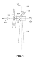
- Fig. 1 is an illustrative block diagram of a set-up of a wind turbine 100 having a tower 102, a machine nacelle 103 and a rotor having a plurality of rotor blades 101 and a hub 105.
- the machine nacelle 103 is adapted to rotate about a tower axis 107 by a predefined amount, e.g. by a yaw angle 106.
- the machine nacelle 103 furthermore includes a gear box 109 which is used to connect a main shaft of the rotor to a generator adapted for supplying electrical output energy.
- a rotor axis 108 may be adjusted with respect to an incoming wind direction 105. Specifically, the rotor axis 108 can be adjusted in order to point towards the incoming wind direction 105, as it is depicted more clearly in Fig. 2 .
- Fig. 2 is a top view of the wind turbine 100 shown in Fig. 1 .
- the nacelle 103 of the wind turbine is adjusted towards the incoming wind direction 105, e.g. such that the direction of the rotor axis 108 coincides with the direction of the incoming wind 105.
- the machine nacelle 103 can yaw about the tower axis 107 such that the situation shown in Fig. 2 can be realized. This yawing consumes electric energy which is provided by an electrical grid or by auxiliary energy sources.
- the adjustment of the nacelle 103 is required in order to withstand possible storms in case of a grid loss.
- the nacelle is directed towards the incoming wind because storm loads are lower when the wind comes from the front.
- Fig. 3 is a sectional side view of the wind turbine 100 shown in Fig. 1 .
- the rotor having rotor blades 101, the hub 104 rotates about the rotor axis 108.
- an associated transducer/converter device 200 is arranged.
- the associated transducer/converter device 200 itself may be a wind turbine of small size as compared to the wind turbine 100.
- integral means any arrangement known in the art so as to reduce costs, or increase power output, or to formulate an efficiency between the components, and does not necessarily mean mechanically coupled to, even though this is one typical embodiment, and may encompass a less preferred configuration where two components are spaced a predetermined distance from one another but share components, or a connection point, data or other integrated relationship while not being mechanically or electrically coupled to one another.
- Integrated may encompass a configuration where the transducer has a housing and the converter has a second housing, and the components simply share a larger housing, or share a connection point, or are integrated to simply share data. Less preferably, the components may simply be arranged to share at least one functional or spatial relationship relative to one another.
- the associated transducer/converter device can be used to provide electrical output energy which is used to charge an accumulator unit (battery system, energy storage system) which then can provide sufficient power to yaw the machine nacelle 103 about the tower axis 107 in case of a grid failure.
- the associated transducer/converter device can be used as an environmental monitoring apparatus adapted for the detection of environmental conditions of the wind turbine.
- the associated transducer/converter device 200 may be arranged rotatable with respect to the machine nacelle 103 about a substantially vertical axis in order to direct the associated transducer/converter device 200 towards the incoming wind direction. Energy which is required for such a rotation may be supplied via a solar cell mounted at the associated transducer/converter device 200. Furthermore the associated transducer/converter device 200 may be self aligning. The associated transducer/converter device 200 may be an anemometer means.
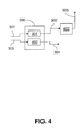
- Fig. 4 is a block diagram showing the associated transducer/converter device which is used as a sensor and an energy converter.
- the associated transducer/converter device 200 includes a transducer device 401 and a converter device 402.
- the transducer device 401 is adapted to detect environmental conditions 301 and to provide an electrical detection signal 302 in dependence of the detected environmental conditions 301.
- the electrical detection signal 302 which is output by the transducer device 401 of the associated transducer/converter device 200 is fed to a processor unit 403 which is adapted to process the electrical detection signal 302 such that a process detection signal 305 can be provided.
- the process detection signal 305 can be used to measure environmental conditions of the wind turbine 100 shown in Fig. 1 , e.g. wind direction, wind velocity or other environmental conditions, such as light intensity.
- a wind turbulence intensity may be derived from temporally resolved wind speed measurements.
- the associated transducer/converter device includes a converter device 402 which converts environmental energy 303 provided by the environment of the wind turbine 100 into electrical output energy 304.
- the environmental energy 303 which is input into the converter device 402 of the associated transducer/converter device 200 may be wind energy (i.e. mechanical energy) or light energy (light intensity).
- the output energy 304 output by the converter device 402 of the associated transducer/converter device may be used as energy in order to provide a yawing of the machine nacelle 103 about the tower axis 107.
- the output energy 304 may be provided as an auxiliary power supply for electrical devices of the wind turbine 100.
- the electrical output energy 304 may be used e.g. to heat the rotor blades 101 of the rotor of the wind turbine in order to prevent icing.
- the associated transducer/converter device is designed as a combination unit wherein both a transducer device for environmental sensing and a converter device for energy conversion is included.
- these environmental conditions may include wind velocity, wind direction and/or wind turbulence.
- the associated transducer/converter device is not restricted to transducer devices for measuring wind conditions. In addition to the measurement of wind conditions, it is possible to monitor light intensities wherein the transducer device is a light intensity sensor and the converter device is a solar cell.
- the associated transducer/converter device includes a wind speed and wind direction sensor and the converter device includes an electrical generator.
- the wind speed and wind direction sensor is adapted to detect wind turbulences.
- the yawing power which is required in order to yaw the nacelle 103 of the wind turbine 100 towards the incoming wind direction 105 the yawing power is 6 kW with a peak at 11 kW.
- This amount of power may be provided by an accumulator unit or a battery system which is charged using the auxiliary power supply over a long time. During yawing the stored energy is consumed in a comparatively short time.
- Fig. 5 is a top view of a wind turbine 100 wherein two transducer/converter devices are arranged atop the machine nacelle 103.
- a first transducer/converter device 201 is arranged having its axis parallel to the rotor axis 108.
- a second transducer/converter device 202 is arranged atop the machine nacelle, wherein the axis of the second transducer/converter device 202 is arranged substantially orthogonal to the rotor axis 108.
- the arrangement of the two transducer/converter devices 201, 202 is such that at least one of the two transducer/converter devices 201, 202 is directed substantially towards the incoming wind direction.
- environmental conditions such as wind directions and wind turbulence can be measured even if the environmental conditions are changing rapidly.
- Fig. 6 is a top view of the wind turbine 100 shown in Fig. 1 , wherein first and second associated transducer/converter devices 201 and 202, respectively, are arranged atop the machine nacelle 103, according to another typical embodiment.
- the first and second transducer/converter devices 201 and 202 are arranged having their axes substantially orthogonal to each other and at an angle of about 45° with respect to the rotor axis 108. Thus, different wind directions can be measured and wind energy can be converted into electrical energy even if the incoming wind direction 105 does not coincide with the rotor axis 108.
- the arrangement of the two transducer/converter devices 201, 202 is such that at least one of the two transducer/converter devices 201, 202 is directed substantially towards the incoming wind direction.
- wind energy may be converted even if the incoming wind direction is changing.
- the at least one associated transducer/converter device 200 may be arranged directly at the tower 102. In this case, the at least one associated transducer/converter device does not rotate together with the machine nacelle about the horizontal tower axis 107.
- the transducer device 401 and the converter device 402 are formed as an associated unit. Furthermore, the transducer device 401, the converter device 402 and the processor unit 403 may be formed as an associated unit.
- the at least two transducer/converter devices 201, 202 are arranged at the machine nacelle with their detection axes oriented substantially orthogonal to each other.
- transducer device 401 as depicted in Fig. 4 is designed as a wind speed and wind direction sensor, this sensor can be adapted to detect wind turbulences.
- the wind speed sensor device for measuring a wind speed vector may include an anemometer means and a signal processing means for analysing the anemometer output signal.
- the wind speed sensor device may further include a means for converting mechanical energy provided by wind forces into electrical energy, wherein the electrical energy is provided for electrical devices as an auxiliary power supply.
- the wind turbine 100 may include at least the anemometer means and the signal processing means for analyzing an anemometer output signal.
- Fig. 7 is a graph illustrating a method for measuring environmental conditions of a wind turbine according to another typical embodiment.
- the method for measuring environmental conditions of a wind turbine including a tower, a machine nacelle and a rotor having a plurality of rotor blades and a hub, includes the steps of detecting the environmental conditions of the wind turbine by means of a transducer device, and supplying auxiliary power to electrical devices of the wind turbine by means of a converter device, wherein the transducer device and the converter device are formed as an associated unit.
- the steps of detecting the environmental conditions of the wind turbine 100 and the steps of supplying auxiliary power to electrical devices of the wind turbine 100 may be carried out independently. In addition to that, the steps of detecting the environmental conditions of the wind turbine and of supplying auxiliary power to electrical devices of the wind turbine may be carried out in an interleaved manner.
- the steps of detecting the environmental conditions of the wind turbine 100 and of supplying auxiliary power to electrical devices of the wind turbine may be carried out simultaneously.
- the auxiliary power may be used, as an example, for the yawing and/or pitching of the rotor blades of the wind turbine.
- the yawing may be performed in different modes including at least one of different yaw speeds, different settings for a maximum allowed cable twist and a maximum allowed yaw misalignment. These modes may be selected based on various inputs such as past and actual wind speed, accumulator energy level, yaw misalignment, grid availability, etc.
Landscapes
- Engineering & Computer Science (AREA)
- Life Sciences & Earth Sciences (AREA)
- Sustainable Development (AREA)
- Sustainable Energy (AREA)
- Chemical & Material Sciences (AREA)
- Combustion & Propulsion (AREA)
- Mechanical Engineering (AREA)
- General Engineering & Computer Science (AREA)
- Wind Motors (AREA)
Applications Claiming Priority (1)
| Application Number | Priority Date | Filing Date | Title |
|---|---|---|---|
| US12/248,925 US20100090463A1 (en) | 2008-10-10 | 2008-10-10 | Combined environmental monitoring and power supply device |
Publications (2)
| Publication Number | Publication Date |
|---|---|
| EP2175127A2 true EP2175127A2 (de) | 2010-04-14 |
| EP2175127A3 EP2175127A3 (de) | 2013-07-17 |
Family
ID=41203656
Family Applications (1)
| Application Number | Title | Priority Date | Filing Date |
|---|---|---|---|
| EP09172048.2A Withdrawn EP2175127A3 (de) | 2008-10-10 | 2009-10-02 | Windturbine, Umweltüberwachungsgerät und Verfahren zum Vermessung von Umweltbedingungen einer Windenergieanlage |
Country Status (3)
| Country | Link |
|---|---|
| US (1) | US20100090463A1 (de) |
| EP (1) | EP2175127A3 (de) |
| CN (1) | CN101726762A (de) |
Cited By (2)
| Publication number | Priority date | Publication date | Assignee | Title |
|---|---|---|---|---|
| WO2013004244A3 (en) * | 2011-07-04 | 2013-04-18 | Vestas Wind Systems A/S | A method of yawing a rotor of a wind turbine |
| EP3211222A1 (de) * | 2016-02-29 | 2017-08-30 | Mitsubishi Heavy Industries, Ltd. | Windturbine, giersteuerungsvorrichtung und betriebssteuerungsverfahren |
Families Citing this family (10)
| Publication number | Priority date | Publication date | Assignee | Title |
|---|---|---|---|---|
| JP5033033B2 (ja) * | 2008-03-27 | 2012-09-26 | 富士重工業株式会社 | 水平軸風車の乱流強度計測方法 |
| US8427000B2 (en) * | 2009-06-24 | 2013-04-23 | Alex Ignatiev | Dual-mode roadway turbines for energy generation from artificial pulsed vehicle wind and continuous ambient wind |
| US8365471B2 (en) * | 2010-02-01 | 2013-02-05 | Aluma Tower Company, Inc. | Automated telescoping tower |
| US9774198B2 (en) * | 2010-11-08 | 2017-09-26 | Brandon Culver | Wind and solar powered heat trace with homeostatic control |
| US9231441B2 (en) * | 2011-04-25 | 2016-01-05 | Hitachi, Ltd. | Wind power generation system, device using wind power generation system, and method for operating same |
| US9753050B2 (en) * | 2013-02-15 | 2017-09-05 | Vestas Wind Systems A/S | Wind turbine component having an optical fibre wind sensor |
| KR101449535B1 (ko) * | 2013-08-05 | 2014-10-13 | 한국전력공사 | 풍력 터빈 블레이드의 상태 감시를 위한 신호 처리 장치 및 그 방법 |
| JP6200748B2 (ja) | 2013-09-30 | 2017-09-20 | 株式会社日立製作所 | 風力発電設備 |
| CN105649895B (zh) * | 2015-12-29 | 2020-07-17 | 北京金风科创风电设备有限公司 | 用于风力发电机组的温度传感器、安装、控制方法及装置 |
| CN112855446A (zh) * | 2019-11-27 | 2021-05-28 | 新疆金风科技股份有限公司 | 风力发电机组 |
Family Cites Families (29)
| Publication number | Priority date | Publication date | Assignee | Title |
|---|---|---|---|---|
| CH472133A (de) * | 1966-11-25 | 1969-04-30 | Varta Ag | Elektrische Energieversorgungsanlage mit einem Windkraftgenerator |
| CH485335A (de) * | 1968-08-28 | 1970-01-31 | Siemens Ag | Verfahren zur wartungsfreien und betriebsbereiten Stillsetzung von Brennstoffzellenbatterien |
| AT356217B (de) * | 1976-08-19 | 1980-04-10 | Siemens Ag | Schaltungsanordnung zur ueberwachung einer wechselspannung |
| GB2263734B (en) * | 1992-01-31 | 1995-11-29 | Declan Nigel Pritchard | Smoothing electrical power output from means for generating electricity from wind |
| US6028414A (en) * | 1997-01-29 | 2000-02-22 | H Power Enterprises Of Canada Inc. | Fuel cell stand-by energy supply system |
| DE19714512C2 (de) * | 1997-04-08 | 1999-06-10 | Tassilo Dipl Ing Pflanz | Maritime Kraftwerksanlage mit Herstellungsprozeß zur Gewinnung, Speicherung und zum Verbrauch von regenerativer Energie |
| US5907192A (en) * | 1997-06-09 | 1999-05-25 | General Electric Company | Method and system for wind turbine braking |
| DE10033029B4 (de) * | 2000-07-07 | 2004-03-18 | Wobben, Aloys, Dipl.-Ing. | Notstromversorgungseinrichtung |
| US20020084655A1 (en) * | 2000-12-29 | 2002-07-04 | Abb Research Ltd. | System, method and computer program product for enhancing commercial value of electrical power produced from a renewable energy power production facility |
| CN1284928C (zh) * | 2001-12-28 | 2006-11-15 | 三菱重工业株式会社 | 逆风型风力涡轮机及其操作方法 |
| ATE441030T1 (de) * | 2002-03-08 | 2009-09-15 | Ocean Wind Energy Systems | Offshore-windenergieanlage |
| US6787259B2 (en) * | 2002-09-12 | 2004-09-07 | Metallic Power, Inc. | Secondary power source for use in a back-up power system |
| JP4058439B2 (ja) * | 2002-09-13 | 2008-03-12 | プロトン エネルギー システムズ,インク. | 電力システム |
| US6921985B2 (en) * | 2003-01-24 | 2005-07-26 | General Electric Company | Low voltage ride through for wind turbine generators |
| EP1604175A2 (de) * | 2003-03-10 | 2005-12-14 | Sensor Wireless Incorporated | Vorrichtung zur erkennung und meldung von umgebungsbedingungen bei massenverarbeitung und güterumschlag |
| US7011902B2 (en) * | 2003-03-12 | 2006-03-14 | Ballard Power Systems Inc. | Black start method and apparatus for a fuel cell power plant, and fuel cell power plant with black start capability |
| ES2402150T3 (es) * | 2003-04-08 | 2013-04-29 | Converteam Gmbh | Turbina eólica para la producción de energía eléctrica y procedimiento de funcionamiento |
| US7233129B2 (en) * | 2003-05-07 | 2007-06-19 | Clipper Windpower Technology, Inc. | Generator with utility fault ride-through capability |
| US6838923B2 (en) * | 2003-05-16 | 2005-01-04 | Ballard Power Systems Inc. | Power supply and ultracapacitor based battery simulator |
| US7250231B2 (en) * | 2003-06-09 | 2007-07-31 | Idatech, Llc | Auxiliary fuel cell system |
| JP4304023B2 (ja) * | 2003-08-07 | 2009-07-29 | 富士重工業株式会社 | 水平軸風車及び水平軸風車の制御方法 |
| US7471010B1 (en) * | 2004-09-29 | 2008-12-30 | Alliance For Sustainable Energy, Llc | Wind turbine tower for storing hydrogen and energy |
| DE102005010399B4 (de) * | 2005-03-07 | 2010-08-05 | Airbus Deutschland Gmbh | Luftfahrzeug mit einem Brennstoffzellen-Notsystem und Verfahren zur außenluftunabhängigen Energie-Notversorgung |
| US7454968B2 (en) * | 2005-06-08 | 2008-11-25 | Stein William M | Wind-powered wireless (RF) anemometer |
| JP4738206B2 (ja) * | 2006-02-28 | 2011-08-03 | 三菱重工業株式会社 | 風力発電システム、及びその制御方法 |
| US7355294B2 (en) * | 2006-05-22 | 2008-04-08 | General Electric Company | Method and system for wind turbine blade movement |
| US7391126B2 (en) * | 2006-06-30 | 2008-06-24 | General Electric Company | Systems and methods for an integrated electrical sub-system powered by wind energy |
| US20080112807A1 (en) * | 2006-10-23 | 2008-05-15 | Ulrich Uphues | Methods and apparatus for operating a wind turbine |
| EP1993184B2 (de) * | 2007-05-14 | 2024-04-24 | Siemens Gamesa Renewable Energy A/S | Verfahren zum Starten mindestens eines Teils einer Windkraftanlage, Windkraftanlage und Verwendung der Windkraftanlage |
-
2008
- 2008-10-10 US US12/248,925 patent/US20100090463A1/en not_active Abandoned
-
2009
- 2009-10-02 EP EP09172048.2A patent/EP2175127A3/de not_active Withdrawn
- 2009-10-09 CN CN200910179485A patent/CN101726762A/zh active Pending
Cited By (4)
| Publication number | Priority date | Publication date | Assignee | Title |
|---|---|---|---|---|
| WO2013004244A3 (en) * | 2011-07-04 | 2013-04-18 | Vestas Wind Systems A/S | A method of yawing a rotor of a wind turbine |
| US10202964B2 (en) | 2011-07-04 | 2019-02-12 | Vestas Wind Systems A/S | Method of yawing a rotor of a wind turbine |
| EP3211222A1 (de) * | 2016-02-29 | 2017-08-30 | Mitsubishi Heavy Industries, Ltd. | Windturbine, giersteuerungsvorrichtung und betriebssteuerungsverfahren |
| US10480484B2 (en) | 2016-02-29 | 2019-11-19 | Mitsubishi Heavy Industries, Ltd. | Wind turbine, yaw control device, and operation control method |
Also Published As
| Publication number | Publication date |
|---|---|
| EP2175127A3 (de) | 2013-07-17 |
| CN101726762A (zh) | 2010-06-09 |
| US20100090463A1 (en) | 2010-04-15 |
Similar Documents
| Publication | Publication Date | Title |
|---|---|---|
| EP2175127A2 (de) | Windturbine, Umweltüberwachungsgerät und Verfahren zum Vermessung von Umweltbedingungen einer Windenergieanlage | |
| EP1906192B1 (de) | Vorrichtung zur Beurteilung von Sensoren und/oder zur Betriebssteuerung eines Geräts mit einem Sensor | |
| US7952215B2 (en) | Wind turbine generator, wind turbine generator system, and power generation control method of wind turbine generator | |
| US8366389B2 (en) | Methods and apparatus for controlling wind turbine thrust | |
| US8177505B2 (en) | Method for measuring a rotational position of a rotor blade of a wind turbine and measuring device | |
| DK1870596T3 (en) | Device for balancing a rotor | |
| US10767633B2 (en) | Method and system for determining the dynamic twist of a wind turbine blade | |
| EP2390501A2 (de) | Verfahren und System zur Validierung einer Windturbine | |
| EP3599375A1 (de) | System und verfahren zum schutz von windturbinen während einer extremen windrichtungsänderung | |
| Wen et al. | An experimental apparatus for investigating the unsteady aerodynamics of a floating wind turbine | |
| EP4179201B1 (de) | Bestimmung des sonnenlichteffekts auf der windturbinenturmneigung unter verwendung von turmoberbeschleunigungsmessern | |
| WO2015045014A1 (ja) | 風車装置、風車装置の異常検出装置及び風車装置の異常検出方法 | |
| CN205080155U (zh) | 一种风光互补自供电式光纤光栅风速仪 | |
| CN112855446A (zh) | 风力发电机组 | |
| EP4677217A1 (de) | Betrieb einer windenergieanlage | |
| WO2010123461A1 (en) | A wind turbine comprising a rotor | |
| US20250172124A1 (en) | Methods for determining wake behavior and controllers | |
| WO2025131318A1 (en) | Determining aerodynamic rotor imbalance in a wind turbine | |
| CN118462483A (zh) | 一种基于压电材料的智能化双叶片海上风电结构 | |
| KR20130101876A (ko) | 풍력 발전기 | |
| Bossanyi | Challenges and main innovations |
Legal Events
| Date | Code | Title | Description |
|---|---|---|---|
| PUAI | Public reference made under article 153(3) epc to a published international application that has entered the european phase |
Free format text: ORIGINAL CODE: 0009012 |
|
| AK | Designated contracting states |
Kind code of ref document: A2 Designated state(s): AT BE BG CH CY CZ DE DK EE ES FI FR GB GR HR HU IE IS IT LI LT LU LV MC MK MT NL NO PL PT RO SE SI SK SM TR |
|
| RIN1 | Information on inventor provided before grant (corrected) |
Inventor name: KERBER, LUTZ GEORG ARND Inventor name: NIES, JACOB JOHANNES |
|
| PUAL | Search report despatched |
Free format text: ORIGINAL CODE: 0009013 |
|
| AK | Designated contracting states |
Kind code of ref document: A3 Designated state(s): AT BE BG CH CY CZ DE DK EE ES FI FR GB GR HR HU IE IS IT LI LT LU LV MC MK MT NL NO PL PT RO SE SI SK SM TR |
|
| RIC1 | Information provided on ipc code assigned before grant |
Ipc: F03D 7/02 20060101AFI20130607BHEP |
|
| STAA | Information on the status of an ep patent application or granted ep patent |
Free format text: STATUS: THE APPLICATION IS DEEMED TO BE WITHDRAWN |
|
| RIN1 | Information on inventor provided before grant (corrected) |
Inventor name: NIES, JACOB JOHANNES Inventor name: KERBER, LUTZ GEORG ARND |
|
| 18D | Application deemed to be withdrawn |
Effective date: 20130503 |