EP2174821B1 - A fuel shut-off valve assembly - Google Patents
A fuel shut-off valve assembly Download PDFInfo
- Publication number
- EP2174821B1 EP2174821B1 EP10152060A EP10152060A EP2174821B1 EP 2174821 B1 EP2174821 B1 EP 2174821B1 EP 10152060 A EP10152060 A EP 10152060A EP 10152060 A EP10152060 A EP 10152060A EP 2174821 B1 EP2174821 B1 EP 2174821B1
- Authority
- EP
- European Patent Office
- Prior art keywords
- housing
- carrier
- valve assembly
- ring
- fuel
- Prior art date
- Legal status (The legal status is an assumption and is not a legal conclusion. Google has not performed a legal analysis and makes no representation as to the accuracy of the status listed.)
- Active
Links
- 239000000446 fuel Substances 0.000 title claims abstract description 58
- 239000000945 filler Substances 0.000 claims abstract description 11
- 239000000463 material Substances 0.000 description 12
- 239000011248 coating agent Substances 0.000 description 11
- 238000000576 coating method Methods 0.000 description 11
- 238000000034 method Methods 0.000 description 8
- 230000008901 benefit Effects 0.000 description 6
- 238000010276 construction Methods 0.000 description 5
- 239000002828 fuel tank Substances 0.000 description 5
- 229910052751 metal Inorganic materials 0.000 description 5
- 239000002184 metal Substances 0.000 description 5
- 238000005260 corrosion Methods 0.000 description 4
- 238000009434 installation Methods 0.000 description 4
- 230000007797 corrosion Effects 0.000 description 3
- 238000004519 manufacturing process Methods 0.000 description 3
- 239000004033 plastic Substances 0.000 description 3
- 230000008569 process Effects 0.000 description 3
- 230000002829 reductive effect Effects 0.000 description 3
- 238000002407 reforming Methods 0.000 description 3
- 238000007789 sealing Methods 0.000 description 3
- 239000010935 stainless steel Substances 0.000 description 3
- 229910001220 stainless steel Inorganic materials 0.000 description 3
- 229910000975 Carbon steel Inorganic materials 0.000 description 2
- 239000000853 adhesive Substances 0.000 description 2
- 230000001070 adhesive effect Effects 0.000 description 2
- 238000000137 annealing Methods 0.000 description 2
- 230000000712 assembly Effects 0.000 description 2
- 238000000429 assembly Methods 0.000 description 2
- 239000010962 carbon steel Substances 0.000 description 2
- 238000005336 cracking Methods 0.000 description 2
- 230000002093 peripheral effect Effects 0.000 description 2
- 230000003068 static effect Effects 0.000 description 2
- 238000003466 welding Methods 0.000 description 2
- 229910000831 Steel Inorganic materials 0.000 description 1
- 230000004075 alteration Effects 0.000 description 1
- 229910052782 aluminium Inorganic materials 0.000 description 1
- XAGFODPZIPBFFR-UHFFFAOYSA-N aluminium Chemical compound [Al] XAGFODPZIPBFFR-UHFFFAOYSA-N 0.000 description 1
- 238000005452 bending Methods 0.000 description 1
- 238000004891 communication Methods 0.000 description 1
- 230000000052 comparative effect Effects 0.000 description 1
- 239000000356 contaminant Substances 0.000 description 1
- 238000002788 crimping Methods 0.000 description 1
- 238000005520 cutting process Methods 0.000 description 1
- 230000002950 deficient Effects 0.000 description 1
- 230000006866 deterioration Effects 0.000 description 1
- 238000009826 distribution Methods 0.000 description 1
- 238000003912 environmental pollution Methods 0.000 description 1
- 230000008020 evaporation Effects 0.000 description 1
- 238000001704 evaporation Methods 0.000 description 1
- -1 for example Substances 0.000 description 1
- 238000007654 immersion Methods 0.000 description 1
- 230000006698 induction Effects 0.000 description 1
- 238000003780 insertion Methods 0.000 description 1
- 230000037431 insertion Effects 0.000 description 1
- 230000000670 limiting effect Effects 0.000 description 1
- 230000014759 maintenance of location Effects 0.000 description 1
- 238000012986 modification Methods 0.000 description 1
- 230000004048 modification Effects 0.000 description 1
- 230000036961 partial effect Effects 0.000 description 1
- 238000003825 pressing Methods 0.000 description 1
- 239000011253 protective coating Substances 0.000 description 1
- 238000012552 review Methods 0.000 description 1
- 238000005096 rolling process Methods 0.000 description 1
- 238000007493 shaping process Methods 0.000 description 1
- 238000005507 spraying Methods 0.000 description 1
- 239000010959 steel Substances 0.000 description 1
- 230000000153 supplemental effect Effects 0.000 description 1
- XLYOFNOQVPJJNP-UHFFFAOYSA-N water Substances O XLYOFNOQVPJJNP-UHFFFAOYSA-N 0.000 description 1
Images


Classifications
-
- B—PERFORMING OPERATIONS; TRANSPORTING
- B60—VEHICLES IN GENERAL
- B60K—ARRANGEMENT OR MOUNTING OF PROPULSION UNITS OR OF TRANSMISSIONS IN VEHICLES; ARRANGEMENT OR MOUNTING OF PLURAL DIVERSE PRIME-MOVERS IN VEHICLES; AUXILIARY DRIVES FOR VEHICLES; INSTRUMENTATION OR DASHBOARDS FOR VEHICLES; ARRANGEMENTS IN CONNECTION WITH COOLING, AIR INTAKE, GAS EXHAUST OR FUEL SUPPLY OF PROPULSION UNITS IN VEHICLES
- B60K15/00—Arrangement in connection with fuel supply of combustion engines or other fuel consuming energy converters, e.g. fuel cells; Mounting or construction of fuel tanks
- B60K15/03—Fuel tanks
- B60K15/04—Tank inlets
- B60K15/05—Inlet covers
-
- B—PERFORMING OPERATIONS; TRANSPORTING
- B60—VEHICLES IN GENERAL
- B60K—ARRANGEMENT OR MOUNTING OF PROPULSION UNITS OR OF TRANSMISSIONS IN VEHICLES; ARRANGEMENT OR MOUNTING OF PLURAL DIVERSE PRIME-MOVERS IN VEHICLES; AUXILIARY DRIVES FOR VEHICLES; INSTRUMENTATION OR DASHBOARDS FOR VEHICLES; ARRANGEMENTS IN CONNECTION WITH COOLING, AIR INTAKE, GAS EXHAUST OR FUEL SUPPLY OF PROPULSION UNITS IN VEHICLES
- B60K15/00—Arrangement in connection with fuel supply of combustion engines or other fuel consuming energy converters, e.g. fuel cells; Mounting or construction of fuel tanks
- B60K15/03—Fuel tanks
- B60K15/04—Tank inlets
- B60K15/0406—Filler caps for fuel tanks
- B60K2015/0419—Self-sealing closure caps, e.g. that don't have to be removed manually
- B60K2015/0429—Self-sealing closure caps, e.g. that don't have to be removed manually actuated by the nozzle
-
- B—PERFORMING OPERATIONS; TRANSPORTING
- B60—VEHICLES IN GENERAL
- B60K—ARRANGEMENT OR MOUNTING OF PROPULSION UNITS OR OF TRANSMISSIONS IN VEHICLES; ARRANGEMENT OR MOUNTING OF PLURAL DIVERSE PRIME-MOVERS IN VEHICLES; AUXILIARY DRIVES FOR VEHICLES; INSTRUMENTATION OR DASHBOARDS FOR VEHICLES; ARRANGEMENTS IN CONNECTION WITH COOLING, AIR INTAKE, GAS EXHAUST OR FUEL SUPPLY OF PROPULSION UNITS IN VEHICLES
- B60K15/00—Arrangement in connection with fuel supply of combustion engines or other fuel consuming energy converters, e.g. fuel cells; Mounting or construction of fuel tanks
- B60K15/03—Fuel tanks
- B60K15/04—Tank inlets
- B60K15/0406—Filler caps for fuel tanks
- B60K2015/0432—Filler caps for fuel tanks having a specific connection between the cap and the vehicle or tank opening
- B60K2015/0445—Filler caps for fuel tanks having a specific connection between the cap and the vehicle or tank opening using hinges
-
- B—PERFORMING OPERATIONS; TRANSPORTING
- B60—VEHICLES IN GENERAL
- B60K—ARRANGEMENT OR MOUNTING OF PROPULSION UNITS OR OF TRANSMISSIONS IN VEHICLES; ARRANGEMENT OR MOUNTING OF PLURAL DIVERSE PRIME-MOVERS IN VEHICLES; AUXILIARY DRIVES FOR VEHICLES; INSTRUMENTATION OR DASHBOARDS FOR VEHICLES; ARRANGEMENTS IN CONNECTION WITH COOLING, AIR INTAKE, GAS EXHAUST OR FUEL SUPPLY OF PROPULSION UNITS IN VEHICLES
- B60K15/00—Arrangement in connection with fuel supply of combustion engines or other fuel consuming energy converters, e.g. fuel cells; Mounting or construction of fuel tanks
- B60K15/03—Fuel tanks
- B60K15/04—Tank inlets
- B60K15/0406—Filler caps for fuel tanks
- B60K2015/0451—Sealing means in the closure cap
Definitions
- the present invention relates to fuel systems for motor vehicles, and more specifically, to primary fuel shut-off valve assemblies in both capless and other refueling systems.
- a fuel shut-of valve assembly according to the preamble of claim 1 is known from US 2003/024599 A1
- Fuel systems for motor vehicles are known to include a fuel tank and a filler tube through which fuel is dispensed into the tank. It is known to use a removable threaded cap at the end of the filler tube to close the tube.
- the threaded fuel cap is the primary seal for the fuel system on most domestic vehicles. For the threaded cap to seal the fuel system properly, the cap must be twisted on correctly. If a fuel cap is not properly tightened, is missing or is defective, a significant amount of fuel can be released to the atmosphere through evaporation from the fuel tank.
- a known assembly of this type includes a metal tube or sleeve and a plastic insert or cover adapted to be received within the sleeve.
- An annular groove is provided on the outer surface of the plastic insert, and a rubber seal or the like is positioned within the groove between the inner surface of the metal sleeve and the outer surface of the plastic insert.
- the sealed area between the insert and the outer sleeve provides a path for the leakage of vapors from the tank. Even a small leak can result in significant loss of fuel and environmental pollution.
- the present invention provides a fuel shut-off valve assembly having a one-piece housing of corrosion resistant material or coated material, or a two-piece housing of coated and uncoated materials; and a carrier and closure assembly that is locked in position after installation via redundant interlocking components.
- the present invention provides a fuel shut-off valve assembly with a housing having an annular rim defining an opening for receiving a fuel filler nozzle therein, and a groove in an outer surface of the annular rim.
- a carrier has a ring surrounding the rim, and the ring has a distal edge disposed in the groove.
- a movable door carried by the carrier selectively opens and closes the inlet.
- An advantage of the present invention is providing a fuel system shut-off valve assembly with a two-piece housing having only a limited access therethrough for a fuel filler nozzle, which can be manufactured of different materials.
- a further advantage of the present invention is providing a fuel shut-off valve assembly that can be manufactured economically and assembled efficiently.
- a still further advantage of the present invention is providing a fuel system shut-off valve assembly that can be assembled quickly and easily yet is secure following assembly with redundant interlocking components.
- Yet another advantage of the present invention is providing a fuel system shutoff valve assembly at least portions of which can be provided of inexpensive materials and easily coated with corrosion resistant coating.
- Figs. 1 to 19 are comparative embodiments which do not form part of the invention.
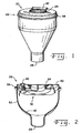
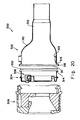
- Fig. 1 is a perspective view of a fuel shut-off valve assembly
- Fig. 2 is a cross-sectional view of a fuel shut-off valve assembly
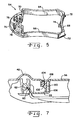
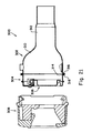
- Fig. 3 is a cross-sectional view illustrating a fuel nozzle inserted into a fuel shut-off valve assembly
- Fig. 4 is a perspective view of a valve door for the fuel shutoff valve assembly
- Fig. 5 is a perspective view of a carrier used in the valve assembly
- Fig. 6 is a perspective view of a biasing spring of the valve assembly
- Fig. 7 is a cross-sectional view of a seal in the valve assembly
- Fig. 8 is a cross-sectional view of an alternate form of a valve assemble during an early stage of manufacture
- Fig. 9 is a cross-sectional view similar to that of Fig. 8 , but illustrating a subsequent step during manufacture of the valve assembly;
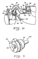
- Fig. 10 is a cross-sectional view of another embodiment of a seal for the valve assembly
- Fig. 11 is a perspective view of the shut-off valve assembly with an outer closure or cover assembly attached thereto in a capless refueling system;
- Fig. 12 is a perspective view of a first step of the final assembly for the capless refueling system
- Fig. 13 is a fragmentary cross-sectional view of the assembly shown in Fig. 12 ;
- Fig. 14 is a cross-sectional view of the partial assembly shown in Fig. 12 , illustrating the structure by which the parts are keyed one to another for proper final orientation;
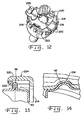
- Fig. 15 is a perspective view of the final stages of assembly for the shut-off valve assembly and cover in the capless refueling system
- Fig. 16 is a fragmentary view of the assembly shown in Fig. 15 ;
- Fig. 17 is a fragmentary perspective view of the final assembly
- Fig. 18 is a perspective view of a second embodiment for a carrier used in the valve assembly
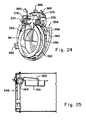
- Fig. 20 is an exploded view, partially broken away, of a fuel system having a fuel shutoff valve assembly of the present invention with a two-piece housing;
- Fig. 23 is an exploded view similar to that of Fig. 22 but illustrating the fuel shutoff valve in a further state of assembly;
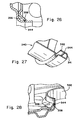
- Fig. 28 is a fragmentary cross-sectional view of another portion of the housing and carrier
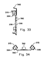
- Fig. 31 is an end view of the housing
- Fig. 32 is a plan view of the carrier
- housing 30 includes a radially outwardly extending outer ring 38 formed by pinching or the like.
- Housing 30 includes a substantially closed end plate 40 in which inlet 24 is defined.
- a dimple or enlargement 42 is provided in end plate 40.
- ring 38 and enlargement 42 define a channel 44 and cavity 46, respectively, for the securement and operation of valve door assembly 32, as will be described in greater detail hereinafter.
- a deformable collar on one of the components crimped over a flange on the other of the components as described in the exemplary embodiments is merely one suitable structure for securing the inner and outer housing components together, and other fastening arrangements also can be used, such as but not limited to bonding with adhesives, welding and the like, physical connectors either separate from the components or integral with the components, interference engagements between components, threaded and other interlocking engagements, and the like.
Landscapes
- Engineering & Computer Science (AREA)
- Life Sciences & Earth Sciences (AREA)
- Sustainable Development (AREA)
- Sustainable Energy (AREA)
- Chemical & Material Sciences (AREA)
- Combustion & Propulsion (AREA)
- Transportation (AREA)
- Mechanical Engineering (AREA)
- Cooling, Air Intake And Gas Exhaust, And Fuel Tank Arrangements In Propulsion Units (AREA)
- Closures For Containers (AREA)
Applications Claiming Priority (2)
| Application Number | Priority Date | Filing Date | Title |
|---|---|---|---|
| US92061507P | 2007-03-29 | 2007-03-29 | |
| EP08744299A EP2125418A2 (en) | 2007-03-29 | 2008-03-25 | Improvements to fuel shut-off valve assemblies and methods of making and assembling the same |
Related Parent Applications (1)
| Application Number | Title | Priority Date | Filing Date |
|---|---|---|---|
| EP08744299.2 Division | 2008-03-25 |
Publications (2)
| Publication Number | Publication Date |
|---|---|
| EP2174821A1 EP2174821A1 (en) | 2010-04-14 |
| EP2174821B1 true EP2174821B1 (en) | 2011-03-16 |
Family
ID=39580076
Family Applications (2)
| Application Number | Title | Priority Date | Filing Date |
|---|---|---|---|
| EP10152060A Active EP2174821B1 (en) | 2007-03-29 | 2008-03-25 | A fuel shut-off valve assembly |
| EP08744299A Withdrawn EP2125418A2 (en) | 2007-03-29 | 2008-03-25 | Improvements to fuel shut-off valve assemblies and methods of making and assembling the same |
Family Applications After (1)
| Application Number | Title | Priority Date | Filing Date |
|---|---|---|---|
| EP08744299A Withdrawn EP2125418A2 (en) | 2007-03-29 | 2008-03-25 | Improvements to fuel shut-off valve assemblies and methods of making and assembling the same |
Country Status (6)
| Country | Link |
|---|---|
| EP (2) | EP2174821B1 (enExample) |
| JP (1) | JP5346007B2 (enExample) |
| CN (1) | CN101600594A (enExample) |
| AT (1) | ATE501884T1 (enExample) |
| DE (1) | DE602008005598D1 (enExample) |
| WO (1) | WO2008121605A2 (enExample) |
Families Citing this family (9)
| Publication number | Priority date | Publication date | Assignee | Title |
|---|---|---|---|---|
| JP5494291B2 (ja) | 2010-06-30 | 2014-05-14 | 豊田合成株式会社 | 燃料タンクの開閉装置 |
| DE112013001704B4 (de) | 2012-03-29 | 2018-05-09 | Honda Motor Co., Ltd. | Öffnungs- und Schliessvorrichtung eines Kraftstofftanks |
| JP6025421B2 (ja) * | 2012-06-29 | 2016-11-16 | 株式会社ニフコ | 弁装置 |
| CN102994886B (zh) * | 2012-09-29 | 2016-01-20 | 合肥康龄养生科技有限公司 | 一种铸造制截止阀阀板的方法 |
| DE102012022129B4 (de) * | 2012-11-13 | 2024-10-10 | Kautex Textron Gmbh & Co. Kg | Elektrisch Leitfähiges Mundstück |
| US9370998B2 (en) * | 2013-09-20 | 2016-06-21 | Honda Motor Co., Ltd. | Fuel filler systems and methods of assembling same |
| DE102014100248A1 (de) * | 2014-01-10 | 2015-07-16 | Illinois Tool Works Inc. | Befüllvorrichtung für einen Fahrzeugtank |
| US9919596B2 (en) | 2015-02-26 | 2018-03-20 | Toyoda Gosei Co., Ltd. | Open-close device for fuel tank |
| CN112250027A (zh) * | 2020-11-20 | 2021-01-22 | 芜湖泰科汽车科技有限公司 | 一种端部带有密封盖板的加油枪密封装置 |
Family Cites Families (11)
| Publication number | Priority date | Publication date | Assignee | Title |
|---|---|---|---|---|
| FR2588806B1 (fr) * | 1985-10-23 | 1990-07-20 | Journee Paul Sa | Dispositif de verrouillage d'un reservoir de carburant de vehicule automobile |
| FR2710721B1 (fr) * | 1993-09-29 | 1995-11-24 | Journee Paul Sa | Tête de remplissage pour une canalisation de remplissage d'un réservoir de véhicule automobile. |
| US5732840A (en) * | 1995-04-21 | 1998-03-31 | Stant Manufacturing Inc. | Closure assembly for a tank filler neck |
| FR2761934B1 (fr) * | 1997-04-14 | 1999-05-14 | Journee Paul Sa | Dispositif de remplissage d'un reservoir de carburant pour un vehicule automobile comportant une tete de remplissage a armature de renfort |
| US6705481B2 (en) * | 1998-03-20 | 2004-03-16 | Temtec Fahrzeutechnick | Actuatable fuel tank closure having guide pipe |
| DE60026414T2 (de) * | 1999-09-22 | 2006-10-26 | Toyoda Gosei Co., Ltd. | Betankungsvorrichtung |
| US6330893B1 (en) * | 1999-12-03 | 2001-12-18 | Shelby Enterprises, Inc. | Fuel tank filter neck and method of manufacturing same |
| JP4563572B2 (ja) * | 2000-12-01 | 2010-10-13 | 本田技研工業株式会社 | 燃料タンクのフィラーチューブ |
| US6685043B1 (en) * | 2001-09-24 | 2004-02-03 | Common Sense Management, Inc. | Quick fill |
| US7549443B2 (en) * | 2003-12-09 | 2009-06-23 | Illinois Tool Works Inc. | Fuel shut-off valve assembly with associated components and methods of making and assembling the same |
| JP2007008429A (ja) * | 2005-07-04 | 2007-01-18 | Asteer Co Ltd | 燃料給油管 |
-
2008
- 2008-03-25 EP EP10152060A patent/EP2174821B1/en active Active
- 2008-03-25 AT AT10152060T patent/ATE501884T1/de not_active IP Right Cessation
- 2008-03-25 JP JP2010501156A patent/JP5346007B2/ja not_active Expired - Fee Related
- 2008-03-25 DE DE602008005598T patent/DE602008005598D1/de active Active
- 2008-03-25 WO PCT/US2008/058105 patent/WO2008121605A2/en not_active Ceased
- 2008-03-25 EP EP08744299A patent/EP2125418A2/en not_active Withdrawn
- 2008-03-25 CN CNA2008800040088A patent/CN101600594A/zh active Pending
Also Published As
| Publication number | Publication date |
|---|---|
| JP2010522665A (ja) | 2010-07-08 |
| EP2125418A2 (en) | 2009-12-02 |
| WO2008121605A2 (en) | 2008-10-09 |
| CN101600594A (zh) | 2009-12-09 |
| ATE501884T1 (de) | 2011-04-15 |
| WO2008121605A3 (en) | 2009-05-07 |
| DE602008005598D1 (de) | 2011-04-28 |
| EP2174821A1 (en) | 2010-04-14 |
| JP5346007B2 (ja) | 2013-11-20 |
Similar Documents
| Publication | Publication Date | Title |
|---|---|---|
| US8651151B2 (en) | Fuel shut-off valve assemblies and methods of making and assembling the same | |
| US7617604B2 (en) | Fuel shut-off valve assembly with associated components and methods of making and assembling the same | |
| EP2174821B1 (en) | A fuel shut-off valve assembly | |
| US6296014B1 (en) | Check valve and fuel tank with check valve attached thereto | |
| US20110079322A1 (en) | Fuel filler system | |
| US7458385B2 (en) | Flapper type fill tube check valve | |
| US6945290B1 (en) | Check valve for use in filler tube vapor recirculation system and method of making same | |
| US9725213B2 (en) | Metallic bung closure with protective plastic layer | |
| EP1637382B1 (en) | Breakaway closure for capless tank filler neck | |
| EP2777972B1 (en) | Fueling portion structure of fuel tank | |
| US5385179A (en) | Nozzle restrictor assembly | |
| EP3402689B1 (en) | Closure assembly for fuel-tank filler neck | |
| US20020104853A1 (en) | Fluid product dispenser with snap-on fixing ring | |
| JPH06336122A (ja) | 自動閉鎖される燃料タンク栓 | |
| WO2003062006A1 (en) | Valve assembly for a fuel tank | |
| US10059198B2 (en) | Improper fuel nozzle insertion-inhibiting assembly | |
| US7096899B2 (en) | Automatic tank closure for a fuel tank | |
| US20050028873A1 (en) | Siphonable poppet-type fill tube check valve | |
| US20160039280A1 (en) | Improper fuel nozzle insertion-inhibiting system | |
| CN100413723C (zh) | 具有相关构件的燃料关闭阀组件及其制造和组装方法 | |
| US20080129046A1 (en) | Attachment System For Fuel Pipe Assemblies and Method of Assembly Therefore | |
| US20060086736A1 (en) | Fuel cap and filler tube combination and method therefor | |
| US5325979A (en) | Fuel erroneous supply prevention shutter | |
| JPH06262954A (ja) | 燃料タンクの給油口ユニット | |
| US20150136768A1 (en) | Fuel filler systems and methods of assembling same |
Legal Events
| Date | Code | Title | Description |
|---|---|---|---|
| PUAI | Public reference made under article 153(3) epc to a published international application that has entered the european phase |
Free format text: ORIGINAL CODE: 0009012 |
|
| 17P | Request for examination filed |
Effective date: 20100129 |
|
| AC | Divisional application: reference to earlier application |
Ref document number: 2125418 Country of ref document: EP Kind code of ref document: P |
|
| AK | Designated contracting states |
Kind code of ref document: A1 Designated state(s): AT BE BG CH CY CZ DE DK EE ES FI FR GB GR HR HU IE IS IT LI LT LU LV MC MT NL NO PL PT RO SE SI SK TR |
|
| AX | Request for extension of the european patent |
Extension state: AL BA MK RS |
|
| 17Q | First examination report despatched |
Effective date: 20100326 |
|
| GRAP | Despatch of communication of intention to grant a patent |
Free format text: ORIGINAL CODE: EPIDOSNIGR1 |
|
| GRAS | Grant fee paid |
Free format text: ORIGINAL CODE: EPIDOSNIGR3 |
|
| GRAA | (expected) grant |
Free format text: ORIGINAL CODE: 0009210 |
|
| AC | Divisional application: reference to earlier application |
Ref document number: 2125418 Country of ref document: EP Kind code of ref document: P |
|
| AK | Designated contracting states |
Kind code of ref document: B1 Designated state(s): AT BE BG CH CY CZ DE DK EE ES FI FR GB GR HR HU IE IS IT LI LT LU LV MC MT NL NO PL PT RO SE SI SK TR |
|
| REG | Reference to a national code |
Ref country code: GB Ref legal event code: FG4D |
|
| REG | Reference to a national code |
Ref country code: CH Ref legal event code: EP |
|
| REG | Reference to a national code |
Ref country code: IE Ref legal event code: FG4D |
|
| REF | Corresponds to: |
Ref document number: 602008005598 Country of ref document: DE Date of ref document: 20110428 Kind code of ref document: P |
|
| REG | Reference to a national code |
Ref country code: DE Ref legal event code: R096 Ref document number: 602008005598 Country of ref document: DE Effective date: 20110428 |
|
| REG | Reference to a national code |
Ref country code: NL Ref legal event code: VDEP Effective date: 20110316 |
|
| PG25 | Lapsed in a contracting state [announced via postgrant information from national office to epo] |
Ref country code: LV Free format text: LAPSE BECAUSE OF FAILURE TO SUBMIT A TRANSLATION OF THE DESCRIPTION OR TO PAY THE FEE WITHIN THE PRESCRIBED TIME-LIMIT Effective date: 20110316 Ref country code: SE Free format text: LAPSE BECAUSE OF FAILURE TO SUBMIT A TRANSLATION OF THE DESCRIPTION OR TO PAY THE FEE WITHIN THE PRESCRIBED TIME-LIMIT Effective date: 20110316 Ref country code: NO Free format text: LAPSE BECAUSE OF FAILURE TO SUBMIT A TRANSLATION OF THE DESCRIPTION OR TO PAY THE FEE WITHIN THE PRESCRIBED TIME-LIMIT Effective date: 20110616 Ref country code: LT Free format text: LAPSE BECAUSE OF FAILURE TO SUBMIT A TRANSLATION OF THE DESCRIPTION OR TO PAY THE FEE WITHIN THE PRESCRIBED TIME-LIMIT Effective date: 20110316 Ref country code: ES Free format text: LAPSE BECAUSE OF FAILURE TO SUBMIT A TRANSLATION OF THE DESCRIPTION OR TO PAY THE FEE WITHIN THE PRESCRIBED TIME-LIMIT Effective date: 20110627 Ref country code: HR Free format text: LAPSE BECAUSE OF FAILURE TO SUBMIT A TRANSLATION OF THE DESCRIPTION OR TO PAY THE FEE WITHIN THE PRESCRIBED TIME-LIMIT Effective date: 20110316 Ref country code: GR Free format text: LAPSE BECAUSE OF FAILURE TO SUBMIT A TRANSLATION OF THE DESCRIPTION OR TO PAY THE FEE WITHIN THE PRESCRIBED TIME-LIMIT Effective date: 20110617 |
|
| LTIE | Lt: invalidation of european patent or patent extension |
Effective date: 20110316 |
|
| PG25 | Lapsed in a contracting state [announced via postgrant information from national office to epo] |
Ref country code: BG Free format text: LAPSE BECAUSE OF FAILURE TO SUBMIT A TRANSLATION OF THE DESCRIPTION OR TO PAY THE FEE WITHIN THE PRESCRIBED TIME-LIMIT Effective date: 20110616 Ref country code: FI Free format text: LAPSE BECAUSE OF FAILURE TO SUBMIT A TRANSLATION OF THE DESCRIPTION OR TO PAY THE FEE WITHIN THE PRESCRIBED TIME-LIMIT Effective date: 20110316 Ref country code: SI Free format text: LAPSE BECAUSE OF FAILURE TO SUBMIT A TRANSLATION OF THE DESCRIPTION OR TO PAY THE FEE WITHIN THE PRESCRIBED TIME-LIMIT Effective date: 20110316 Ref country code: AT Free format text: LAPSE BECAUSE OF FAILURE TO SUBMIT A TRANSLATION OF THE DESCRIPTION OR TO PAY THE FEE WITHIN THE PRESCRIBED TIME-LIMIT Effective date: 20110316 Ref country code: CY Free format text: LAPSE BECAUSE OF FAILURE TO SUBMIT A TRANSLATION OF THE DESCRIPTION OR TO PAY THE FEE WITHIN THE PRESCRIBED TIME-LIMIT Effective date: 20110316 |
|
| PG25 | Lapsed in a contracting state [announced via postgrant information from national office to epo] |
Ref country code: BE Free format text: LAPSE BECAUSE OF FAILURE TO SUBMIT A TRANSLATION OF THE DESCRIPTION OR TO PAY THE FEE WITHIN THE PRESCRIBED TIME-LIMIT Effective date: 20110316 |
|
| PG25 | Lapsed in a contracting state [announced via postgrant information from national office to epo] |
Ref country code: MC Free format text: LAPSE BECAUSE OF NON-PAYMENT OF DUE FEES Effective date: 20110331 Ref country code: EE Free format text: LAPSE BECAUSE OF FAILURE TO SUBMIT A TRANSLATION OF THE DESCRIPTION OR TO PAY THE FEE WITHIN THE PRESCRIBED TIME-LIMIT Effective date: 20110316 Ref country code: PT Free format text: LAPSE BECAUSE OF FAILURE TO SUBMIT A TRANSLATION OF THE DESCRIPTION OR TO PAY THE FEE WITHIN THE PRESCRIBED TIME-LIMIT Effective date: 20110718 |
|
| PG25 | Lapsed in a contracting state [announced via postgrant information from national office to epo] |
Ref country code: SK Free format text: LAPSE BECAUSE OF FAILURE TO SUBMIT A TRANSLATION OF THE DESCRIPTION OR TO PAY THE FEE WITHIN THE PRESCRIBED TIME-LIMIT Effective date: 20110316 Ref country code: CZ Free format text: LAPSE BECAUSE OF FAILURE TO SUBMIT A TRANSLATION OF THE DESCRIPTION OR TO PAY THE FEE WITHIN THE PRESCRIBED TIME-LIMIT Effective date: 20110316 Ref country code: IS Free format text: LAPSE BECAUSE OF FAILURE TO SUBMIT A TRANSLATION OF THE DESCRIPTION OR TO PAY THE FEE WITHIN THE PRESCRIBED TIME-LIMIT Effective date: 20110716 Ref country code: RO Free format text: LAPSE BECAUSE OF FAILURE TO SUBMIT A TRANSLATION OF THE DESCRIPTION OR TO PAY THE FEE WITHIN THE PRESCRIBED TIME-LIMIT Effective date: 20110316 |
|
| PG25 | Lapsed in a contracting state [announced via postgrant information from national office to epo] |
Ref country code: MT Free format text: LAPSE BECAUSE OF FAILURE TO SUBMIT A TRANSLATION OF THE DESCRIPTION OR TO PAY THE FEE WITHIN THE PRESCRIBED TIME-LIMIT Effective date: 20110316 Ref country code: NL Free format text: LAPSE BECAUSE OF FAILURE TO SUBMIT A TRANSLATION OF THE DESCRIPTION OR TO PAY THE FEE WITHIN THE PRESCRIBED TIME-LIMIT Effective date: 20110316 |
|
| REG | Reference to a national code |
Ref country code: IE Ref legal event code: MM4A |
|
| PLBE | No opposition filed within time limit |
Free format text: ORIGINAL CODE: 0009261 |
|
| STAA | Information on the status of an ep patent application or granted ep patent |
Free format text: STATUS: NO OPPOSITION FILED WITHIN TIME LIMIT |
|
| PG25 | Lapsed in a contracting state [announced via postgrant information from national office to epo] |
Ref country code: IE Free format text: LAPSE BECAUSE OF NON-PAYMENT OF DUE FEES Effective date: 20110325 |
|
| 26N | No opposition filed |
Effective date: 20111219 |
|
| PG25 | Lapsed in a contracting state [announced via postgrant information from national office to epo] |
Ref country code: PL Free format text: LAPSE BECAUSE OF FAILURE TO SUBMIT A TRANSLATION OF THE DESCRIPTION OR TO PAY THE FEE WITHIN THE PRESCRIBED TIME-LIMIT Effective date: 20110316 |
|
| REG | Reference to a national code |
Ref country code: FR Ref legal event code: ST Effective date: 20120210 |
|
| REG | Reference to a national code |
Ref country code: DE Ref legal event code: R097 Ref document number: 602008005598 Country of ref document: DE Effective date: 20111219 |
|
| PG25 | Lapsed in a contracting state [announced via postgrant information from national office to epo] |
Ref country code: FR Free format text: LAPSE BECAUSE OF NON-PAYMENT OF DUE FEES Effective date: 20110516 |
|
| PG25 | Lapsed in a contracting state [announced via postgrant information from national office to epo] |
Ref country code: IT Free format text: LAPSE BECAUSE OF FAILURE TO SUBMIT A TRANSLATION OF THE DESCRIPTION OR TO PAY THE FEE WITHIN THE PRESCRIBED TIME-LIMIT Effective date: 20110316 |
|
| REG | Reference to a national code |
Ref country code: CH Ref legal event code: PL |
|
| GBPC | Gb: european patent ceased through non-payment of renewal fee |
Effective date: 20120325 |
|
| PG25 | Lapsed in a contracting state [announced via postgrant information from national office to epo] |
Ref country code: LI Free format text: LAPSE BECAUSE OF NON-PAYMENT OF DUE FEES Effective date: 20120331 Ref country code: CH Free format text: LAPSE BECAUSE OF NON-PAYMENT OF DUE FEES Effective date: 20120331 Ref country code: GB Free format text: LAPSE BECAUSE OF NON-PAYMENT OF DUE FEES Effective date: 20120325 |
|
| PG25 | Lapsed in a contracting state [announced via postgrant information from national office to epo] |
Ref country code: LU Free format text: LAPSE BECAUSE OF NON-PAYMENT OF DUE FEES Effective date: 20110325 |
|
| PG25 | Lapsed in a contracting state [announced via postgrant information from national office to epo] |
Ref country code: TR Free format text: LAPSE BECAUSE OF FAILURE TO SUBMIT A TRANSLATION OF THE DESCRIPTION OR TO PAY THE FEE WITHIN THE PRESCRIBED TIME-LIMIT Effective date: 20110316 |
|
| PG25 | Lapsed in a contracting state [announced via postgrant information from national office to epo] |
Ref country code: HU Free format text: LAPSE BECAUSE OF FAILURE TO SUBMIT A TRANSLATION OF THE DESCRIPTION OR TO PAY THE FEE WITHIN THE PRESCRIBED TIME-LIMIT Effective date: 20110316 |
|
| PGFP | Annual fee paid to national office [announced via postgrant information from national office to epo] |
Ref country code: DE Payment date: 20180328 Year of fee payment: 11 |
|
| REG | Reference to a national code |
Ref country code: DE Ref legal event code: R119 Ref document number: 602008005598 Country of ref document: DE |
|
| PG25 | Lapsed in a contracting state [announced via postgrant information from national office to epo] |
Ref country code: DE Free format text: LAPSE BECAUSE OF NON-PAYMENT OF DUE FEES Effective date: 20191001 |