EP2174403B1 - Electric machine, particularly asynchronous three-phase current hydrogenerator - Google Patents
Electric machine, particularly asynchronous three-phase current hydrogenerator Download PDFInfo
- Publication number
- EP2174403B1 EP2174403B1 EP08774630A EP08774630A EP2174403B1 EP 2174403 B1 EP2174403 B1 EP 2174403B1 EP 08774630 A EP08774630 A EP 08774630A EP 08774630 A EP08774630 A EP 08774630A EP 2174403 B1 EP2174403 B1 EP 2174403B1
- Authority
- EP
- European Patent Office
- Prior art keywords
- winding
- bars
- electrical machine
- machine
- another
- Prior art date
- Legal status (The legal status is an assumption and is not a legal conclusion. Google has not performed a legal analysis and makes no representation as to the accuracy of the status listed.)
- Active
Links
Images


Classifications
-
- H—ELECTRICITY
- H02—GENERATION; CONVERSION OR DISTRIBUTION OF ELECTRIC POWER
- H02K—DYNAMO-ELECTRIC MACHINES
- H02K15/00—Methods or apparatus specially adapted for manufacturing, assembling, maintaining or repairing of dynamo-electric machines
- H02K15/0056—Manufacturing winding connections
- H02K15/0068—Connecting winding sections; Forming leads; Connecting leads to terminals
- H02K15/0081—Connecting winding sections; Forming leads; Connecting leads to terminals for form-wound windings
-
- H—ELECTRICITY
- H02—GENERATION; CONVERSION OR DISTRIBUTION OF ELECTRIC POWER
- H02K—DYNAMO-ELECTRIC MACHINES
- H02K3/00—Details of windings
- H02K3/04—Windings characterised by the conductor shape, form or construction, e.g. with bar conductors
- H02K3/12—Windings characterised by the conductor shape, form or construction, e.g. with bar conductors arranged in slots
-
- H—ELECTRICITY
- H02—GENERATION; CONVERSION OR DISTRIBUTION OF ELECTRIC POWER
- H02K—DYNAMO-ELECTRIC MACHINES
- H02K2205/00—Specific aspects not provided for in the other groups of this subclass relating to casings, enclosures, supports
- H02K2205/12—Machines characterised by means for reducing windage losses or windage noise
Definitions
- the present invention relates to the field of electric machines. It relates to a winding of an electrical machine, in particular a hydrogenerator, according to the preamble of claim 1.
- variable-speed drives for energy production Due to the changed market conditions on the open electricity markets and the improved technologies in the field of power electronics, the topic of variable-speed drives for energy production has gained in importance. For this purpose will be especially for outputs above 60 MVA, preferably double-fed asynchronous machines are used.
- the stator of this type of machine does not differ from the salient pole synchronous machines commonly used in this application.
- Machines of this type are characterized by the fact that they are equipped both on the stator and on the rotor with a three-phase winding.
- the winding heads of the rotor winding are arranged on a cylindrical surface ( DE-A1-195 13 457 ).
- FIG. 1 A corresponding (three-phase) winding scheme, for example for a rotor, is in Fig. 1
- the rotor 10 has a rotor yoke 11 in which winding slots 12 extending in the axial direction are provided.
- the winding grooves 12 receive the winding 13, which is formed from winding bars 17, 18.
- Each phase is shown in a different line style (dashed, long dashed, solid).
- Each two winding rods 17, 18 are accommodated in a winding groove superimposed.
- the winding bars 17, 18 come out of the winding grooves 12 and are electrically connected in pairs to one another according to a predetermined pattern within a winding head 13a or 13b at the ends (connections 16).
- the remaining winding rods are led out as terminals 14, 15 to the outside.
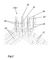
- an upper winding bar 18 of a first winding groove and a lower winding bar 17 of a second winding groove are bent toward each other at the end of the rotor yoke 11 so that the two ends are superimposed in the radial direction, as shown in FIG Fig. 2 in an enlarged detail for a winding head 13a 'is reproduced.
- the rod ends 19, 20 are aligned parallel to one another by a second bend.
- the exposed from the insulation ladder of Winding bars 17, 18 form in this area tabs 21, 22 with a rectangular cross-section, to each of which then an angle-shaped connecting part 23 and 24 is attached.
- the electrically conductive connection 16 ( Fig. 1 ) is finally effected by the connection of the two connecting parts 23, 24.
- the known design of the winding head 13a 'according to Fig. 2 has several disadvantages: First, a second bend on the rod ends 19, 20 is necessary, which requires additional effort. On the other hand, additional copper material is required for the parallel rod ends 19, 20, which not only increases the material costs, but also increases the axial length of the winding overhang and the winding resistance.
- the font US-A-3,675,058 discloses a prefabricated connecting element for an electrodynamic machine which is to be used advantageously in particular in aluminum-equipped engines for operation in corrosive environment.
- the substantially integrally formed as a block-shaped block connecting element (14, 16) has a number of rectangular apertures (30) or slots (38, 42), in the shape and dimension complementarily formed conductor bars (40, 44) are inserted.
- This connecting element (14, 16) also has the disadvantages already mentioned above.
- the ladder bars are to be bent in such a way that they are always parallel or end up perpendicular to each other. Its uses are considerably limited.
- the object is essentially solved in that the integral connecting element, and that the connecting element is designed as oriented in the radial direction round eye which has two crossing superposed in the radial direction abutment surfaces for abutment against the tabs to be joined together winding bars. Since the crossing angle in the winding head in most cases is the same for all compounds, only one type of round eyelet in two versions, which are mirror-inverted, needed. These can be prefabricated in a simple manner. Due to the one-piece construction, the connecting element only needs to be connected to the two bar ends. In particular, there is no danger that the connecting element will disintegrate into individual components under centrifugal force or vibration load. In addition, due to the one-piece advantages in the power line, because the contact resistance is minimized.
- the round eyelet on a cylindrical basic shape wherein the contact surfaces are arranged parallel to the cylinder axis and of the cylinder axis have a distance which corresponds to half the thickness of the tabs.
- the round eyelet has a central piece between the two contact surfaces.
- the length of the tabs is less than or equal to the outer diameter of the eyelet. This avoids that the tabs protrude in a disturbing way on the Rundiere.
- the winding is preferably the rotor winding of the machine. But it can also be the stator winding of the machine.
- FIG. 3 is in one too Fig. 2 comparable representation reproduced the connection of the ends of the winding bars in the winding head 13a of a winding according to a preferred embodiment of the invention.
- the winding rods 17, 18 emerging from the winding grooves and once bent at the end of the winding grooves are supplied to one another without a second bend at the rod ends so that they intersect one another with their (straight) ends in pairs.
- the intersecting ends are exposed by the insulation ladder, which protrude as tabs 21, 22 from the rod ends.
- Coaxial with the crossing axis of the intersecting tabs 21, 22 is arranged as a one-piece, electrically good conductive connecting element a round eyelet 27 which is fixedly connected to the two tabs 21, 22.
- Selected conductor bars whose ends are unconnected are bent a second time in the axial direction and serve with the resulting connection parts 25, 26 for connecting the winding.
- FIG. 4 has a cylindrical basic shape with a cylinder axis 31. Along the cylinder axis 31 are successively, separated by a central piece 30, two axis-parallel, intersecting contact surfaces 28 and 29 are formed.
- the crossing angle of the contact surfaces 28, 29 corresponds to the crossing angle of the intersecting tabs 21, 22.
- the distance A of the contact surfaces 28, 29 to the cylinder axis 31 corresponds to half the thickness D / 2 of the tabs 21, 22 (FIG. Fig. 3 ). In this way, the tabs 21, 22 go with the round eyelet 27 exactly centered through the cylinder of the eyelet 27.
- Fig. 3 the tabs 21, 22 go with the round eyelet 27 exactly centered through the cylinder of the eyelet 27.
- the length of the tabs 21, 22 is less than or equal to the outer diameter of the eyelet 27, so that the tabs 21, 22 do not protrude over the eyelet 27 disturbing.
- the middle piece 30 of the round eyelet the current transition between the rod ends is optimized.
- a material for the round eyelet copper a copper alloy or other electrically conductive material can be used.
- the invention results in a shortened winding head which saves copper, reduces the copper losses, can be supported more easily against centrifugal forces (if the winding is a rotor winding), is easier to manufacture and assemble and has a higher mechanical stability and safety.
- the winding according to the invention can be used both as a rotor winding and as a stator winding.
Abstract
Description
Die vorliegende Erfindung bezieht sich auf das Gebiet der elektrischen Maschinen. Sie betrifft eine Wicklung einer elektrischen Maschine, insbesondere eines Hydrogenerators, gemäss dem Oberbegriff des Anspruchs 1.The present invention relates to the field of electric machines. It relates to a winding of an electrical machine, in particular a hydrogenerator, according to the preamble of claim 1.
Durch die veränderten marktwirtschaftlichen Bedingungen an den geöffneten Strommärkten und den verbesserten Technologien im Bereich der Leistungselektronik hat das Thema drehzahlvariabler Antriebe zur Energieproduktion an Bedeutung gewonnen. Für diesen Zweck werden insbesondere bei Leistungen über 60 MVA bevorzugt doppelt gespeiste Asynchronmaschinen eingesetzt.Due to the changed market conditions on the open electricity markets and the improved technologies in the field of power electronics, the topic of variable-speed drives for energy production has gained in importance. For this purpose will be especially for outputs above 60 MVA, preferably double-fed asynchronous machines are used.
Der Stator dieses Maschinentypus unterscheidet sich nicht von den für diese Anwendung gebräuchlichen Schenkelpolsynchronmaschinen. Maschinen dieses Typs zeichnen sich dadurch aus, dass sie sowohl auf dem Stator wie auch auf dem Rotor mit einer Dreiphasenwicklung ausgestattet sind. Üblicherweise sind dabei die Wickelköpfe der Rotorwicklung auf einer zylindrischen Oberfläche angeordnet (
Ein entsprechendes (dreiphasiges) Wicklungsschema, zum Beispiel für einen Rotor, ist in
Zum paarweisen Verbinden werden im Stand der Technik jeweils ein oberer Wicklungsstab 18 einer ersten Wicklungsnut und ein unterer Wicklungsstab 17 einer zweiten Wicklungsnut am Ende des Rotorjochs 11 derartig aufeinander zugebogen, dass die beiden Enden in radialer Richtung übereinander liegen, wie dies in
Die bekannte Ausbildung des Wickelkopfes 13a' gemäss
Es ist daher in der
Die Schrift
Es ist daher Aufgabe der Erfindung, eine elektrische Maschine der eingangs genannten Art so auszubilden, dass die Nachteile bekannter Maschinen vermieden werden und insbesondere unter Beibehaltung eines axial verkürzten Wickelkopfes eine vereinfachte Montage und gleichzeitig ein mechanisch stabilerer Aufbau ermöglicht werden.It is therefore an object of the invention to form an electrical machine of the type mentioned above in such a way that the disadvantages of known machines are avoided and, in particular while maintaining an axially shortened winding head, a simplified assembly and at the same time a mechanically more stable construction are made possible.
Die Aufgabe wird im Wesentlichen dadurch gelöst, dass das verbindungselement einstückig ist, und dass das Verbindungselement als in radialer Richtung orientierte Rundöse ausgebildet ist, welche zwei in radialer Richtung kreuzend übereinander liegende Anlageflächen zur Anlage an den Laschen der miteinander zu verbindenden Wicklungsstäbe aufweist. Da der Kreuzungswinkel im Wickelkopf in den meisten Fällen für alle Verbindungen gleich ist, wird nur eine Art von Rundöse in zwei Ausführungen, welche zueinander spiegelverkehrt sind, benötigt. Diese können auf einfache Weise vorgefertigt werden. Aufgrund der Einstückigkeit braucht das Verbindungselement nur mit den beiden Stabenden verbunden zu werden. Insbesondere besteht nicht die Gefahr, dass das Verbindungselement bei Fliehkraft- oder Vibrationsbelastung in einzelne Bestandteile zerfällt. Darüber hinaus ergeben sich aufgrund der Einstückigkeit Vorteile bei der Stromleitung, weil die Übergangswiderstände minimiert sind.The object is essentially solved in that the integral connecting element, and that the connecting element is designed as oriented in the radial direction round eye which has two crossing superposed in the radial direction abutment surfaces for abutment against the tabs to be joined together winding bars. Since the crossing angle in the winding head in most cases is the same for all compounds, only one type of round eyelet in two versions, which are mirror-inverted, needed. These can be prefabricated in a simple manner. Due to the one-piece construction, the connecting element only needs to be connected to the two bar ends. In particular, there is no danger that the connecting element will disintegrate into individual components under centrifugal force or vibration load. In addition, due to the one-piece advantages in the power line, because the contact resistance is minimized.
Gemäss einer Ausgestaltung der Erfindung weist die Rundöse eine zylindrische Grundform auf, wobei die Anlageflächen parallel zur Zylinderachse angeordnet sind und von der Zylinderachse einen Abstand aufweisen, welcher der halben Dicke der Laschen entspricht.According to one embodiment of the invention, the round eyelet on a cylindrical basic shape, wherein the contact surfaces are arranged parallel to the cylinder axis and of the cylinder axis have a distance which corresponds to half the thickness of the tabs.
Weiterhin ist es für die elektrischen und mechanischen Eigenschaften von Vorteil, wenn die Rundöse zwischen den beiden Anlageflächen ein Mittelstück aufweist.Furthermore, it is advantageous for the electrical and mechanical properties if the round eyelet has a central piece between the two contact surfaces.
Vorzugsweise ist die Länge der Laschen kleiner oder gleich dem Aussendurchmesser der Rundöse. Dadurch wird vermieden, dass die Laschen auf störende Weise über die Rundöse hinausragen.Preferably, the length of the tabs is less than or equal to the outer diameter of the eyelet. This avoids that the tabs protrude in a disturbing way on the Rundöse.
Die Wicklung ist vorzugsweise die Rotorwicklung der Maschine. Sie kann aber auch die Statorwicklung der Maschine sein.The winding is preferably the rotor winding of the machine. But it can also be the stator winding of the machine.
Die Erfindung soll nachfolgend anhand von Ausführungsbeispielen im Zusammenhang mit der Zeichnung näher erläutert werden. Es zeigen
- Fig. 1
- ein beispielhaftes Wicklungsschema einer dreiphasigen Rotorwicklung eines Drehstrom-Asynchron-Hydrogenerators;
- Fig. 2
- die Verbindung der Enden der Wicklungsstäbe im Wickelkopf einer Wicklung nach
Fig. 1 , wie sie aus dem Stand der Technik bekannt ist; - Fig. 3
- in einer zu
Fig. 2 vergleichbaren Darstellung die Verbindung der Enden der Wicklungsstäbe im Wickelkopf einer Wicklung gemäss einem bevorzugten Ausführungsbeispiel der Erfindung mittels Rundösen;und - Fig. 4
- in mehreren Teilfiguren 4(a) bis 4(c) unterschiedliche Ansichten einer Rundöse aus
Fig. 3 .
- Fig. 1
- an exemplary winding diagram of a three-phase rotor winding of a three-phase asynchronous hydrogenerator;
- Fig. 2
- the connection of the ends of the winding bars in the winding head of a winding
Fig. 1 as known from the prior art; - Fig. 3
- in one too
Fig. 2 Comparative illustration of the connection of the ends of the winding bars in the winding head of a winding according to a preferred embodiment of the invention by means of round eyes; - Fig. 4
- in several sub-figures 4 (a) to 4 (c) different views of a round eyelet
Fig. 3 ,
In
Die eingesetzte Rundöse 27, die in Fig. 4 für sich genommen dargestellt ist, hat eine zylindrische Grundform mit einer Zylinderachse 31. Entlang der Zylinderachse 31 sind hintereinander, getrennt durch ein Mittelstück 30, zwei achsenparallele, sich kreuzende Anlageflächen 28 und 29 ausgebildet. Der Kreuzungswinkel der Anlageflächen 28, 29 entspricht dem Kreuzungswinkel der sich kreuzenden Laschen 21, 22. Der Abstand A der Anlageflächen 28, 29 zur Zylinderachse 31 entspricht der halben Dicke D/2 der Laschen 21, 22 (
Insgesamt ergibt sich mit der Erfindung ein verkürzter Wickelkopf, der Kupfer einspart, die Kupferverluste verringert, sich leichter gegen Zentrifugalkräfte abstützen lässt (wenn die Wicklung eine Rotorwicklung ist), einfacher herzustellen und zu montieren ist und eine höhere mechanische Stabilität und Sicherheit zur Folge hat. Die erfindungsgemässe Wicklung kann sowohl als Rotor- als auch als Statorwicklung eingesetzt werden.Overall, the invention results in a shortened winding head which saves copper, reduces the copper losses, can be supported more easily against centrifugal forces (if the winding is a rotor winding), is easier to manufacture and assemble and has a higher mechanical stability and safety. The winding according to the invention can be used both as a rotor winding and as a stator winding.
- 1010
- Rotorrotor
- 1111
- Rotorjochrotor yoke
- 1212
- Wicklungsnutwinding groove
- 1313
- Wicklungwinding
- 13a,b13a, b
- Wickelkopfwinding
- 14,1514.15
- Anschlussconnection
- 1616
- Verbindungconnection
- 17,1817.18
- Wicklungsstabwinding bar
- 19,2019.20
- Stabende (abgekröpft)Bar end (bent)
- 21,2221.22
- Lascheflap
- 23,2423.24
- Verbindungsteilconnecting part
- 25,2625.26
- Anschlussteil (abgekröpft)Connection part (bent)
- 2727
- Rundöseround eye
- 28,2928.29
- Anlageflächecontact surface
- 3030
- Mittelstückcenterpiece
- 3131
- Zylinderachsecylinder axis
Claims (7)
- An electrical machine, in particular a three-phase asynchronous hydrogenerator, with a rotor (10) and a stator and a winding (13), which comprises a large number of axially extending winding bars (17, 18), which lie one on top of the other in pairs in corresponding winding slots (12) of a core (11), wherein the winding bars (17, 18) emerge from the winding slots (12) at the end sides of the machine, and the majority of said winding bars are electrically connected to one another in pairs in an end winding (13a, 13b) in accordance with a predetermined scheme, wherein in each case one upper winding bar (18) of a first winding slot and one lower winding bar (17) of a second winding slot are bent towards one another in such a way that their ends (21, 22) lie one on top of the other so as to cross one another in the radial direction, and the connection (16) between the winding bars (17, 18) of an electrically connected winding bar pair is produced by means of a connecting element (27), wherein the ends of the electrically interconnected winding bars (17, 18) are in the form of straight lugs (21, 22) with a rectangular cross section, characterized in that the connecting element (27) is integral and in that the connecting element is in the form of a round eyelet (27) which is oriented in the radial direction and has two bearing faces (28, 29), which lie one on top of the other so as to cross one another in the radial direction, for bearing against the lugs (21, 22) of the winding bars (17, 18) to be connected to one another.
- The electrical machine as claimed in claim 1, characterized in that the crossing angles of the mutually crossing winding bar ends (21, 22) and of the mutually crossing bearing faces (28, 29) of the round eyelet (27) are equal.
- The electrical machine as claimed in claim 1 or 2, characterized in that the round eyelet (27) has a cylindrical basic shape, and in that the bearing faces (28, 29) are arranged parallel to the cylinder axis (31) and are spaced apart from the cylinder axis (31) by a distance (A) which corresponds to half the thickness (D/2) of the lugs (21, 22).
- The electrical machine as claimed in one of claims 1 to 3, characterized in that the round eyelet (27) has a central piece (30) between the two bearing faces (28, 29).
- The electrical machine as claimed in claim 3, characterized in that the length of the lugs (21, 22) is less than or equal to the outer diameter of the round eyelet (27).
- The electrical machine as claimed in one of claims 1 to 5, characterized in that the winding (13) is the rotor winding of the machine.
- The electrical machine as claimed in one of claims 1 to 5, characterized in that the winding is the stator winding of the machine.
Applications Claiming Priority (3)
| Application Number | Priority Date | Filing Date | Title |
|---|---|---|---|
| DE102007036806 | 2007-08-03 | ||
| DE102007000661A DE102007000661A1 (en) | 2007-11-08 | 2007-11-08 | Electric machine i.e. asynchronous three-phase current hydro-generator, for power electronics, has lower and upper winding bars arranged in respective winding slots, and single-piece connecting element for connecting winding bars |
| PCT/EP2008/058494 WO2009019087A2 (en) | 2007-08-03 | 2008-07-02 | Electric machine, particularly asynchronous three-phase current hydrogenerator |
Publications (2)
| Publication Number | Publication Date |
|---|---|
| EP2174403A2 EP2174403A2 (en) | 2010-04-14 |
| EP2174403B1 true EP2174403B1 (en) | 2012-08-22 |
Family
ID=39949855
Family Applications (1)
| Application Number | Title | Priority Date | Filing Date |
|---|---|---|---|
| EP08774630A Active EP2174403B1 (en) | 2007-08-03 | 2008-07-02 | Electric machine, particularly asynchronous three-phase current hydrogenerator |
Country Status (8)
| Country | Link |
|---|---|
| US (1) | US8093778B2 (en) |
| EP (1) | EP2174403B1 (en) |
| KR (1) | KR101477487B1 (en) |
| CN (1) | CN101772877B (en) |
| BR (1) | BRPI0814770A2 (en) |
| CA (1) | CA2694137C (en) |
| RU (1) | RU2483413C2 (en) |
| WO (1) | WO2009019087A2 (en) |
Families Citing this family (9)
| Publication number | Priority date | Publication date | Assignee | Title |
|---|---|---|---|---|
| JP5586969B2 (en) * | 2010-01-21 | 2014-09-10 | 株式会社デンソー | Rotating electric machine stator |
| JP5585819B2 (en) * | 2010-03-31 | 2014-09-10 | 株式会社デンソー | Rotating electric machine stator |
| US8671559B2 (en) * | 2011-04-27 | 2014-03-18 | GM Global Technology Operations LLC | System for joining stator wires |
| DE102011106480A1 (en) * | 2011-06-14 | 2012-12-20 | Voith Patent Gmbh | asynchronous |
| KR101432595B1 (en) * | 2011-07-01 | 2014-08-22 | 엘지전자 주식회사 | Stator for electric machine |
| KR101365469B1 (en) * | 2012-09-20 | 2014-02-25 | 현대모비스 주식회사 | Device for hairpin connecting and hairpin winding motor having the same |
| DE102016107929A1 (en) * | 2016-04-28 | 2017-11-02 | Wobben Properties Gmbh | Aluform coil and winding structure and stator of a generator of a wind turbine and method for producing a stator |
| JP6811042B2 (en) * | 2016-07-12 | 2021-01-13 | 日本電産コパル電子株式会社 | Coreless coil and manufacturing method of this coreless coil |
| JP6642494B2 (en) * | 2017-03-10 | 2020-02-05 | トヨタ自動車株式会社 | Manufacturing equipment for stators of rotating electric machines |
Family Cites Families (22)
| Publication number | Priority date | Publication date | Assignee | Title |
|---|---|---|---|---|
| US2407935A (en) * | 1944-05-25 | 1946-09-17 | Chrysler Corp | Electrical machine |
| DE1207999B (en) * | 1964-09-22 | 1965-12-30 | Licentia Gmbh | Solder connection intermediate pieces for runner winding rods of electrical machines |
| US3675058A (en) * | 1970-09-08 | 1972-07-04 | Gen Electric | Dynamoelectric machine utilizing pre-formed winding connectors and method of making |
| SU809447A1 (en) * | 1976-12-07 | 1981-02-28 | Предприятие П/Я А-7676 | Electric machine stator rod winding |
| SU694941A1 (en) * | 1977-11-09 | 1979-10-30 | Производственное предприятие "Ростовэнергоремонт" | Device for anchoring end portions of a multilayer rod winding of a stator of an electric machine |
| SU1390711A1 (en) * | 1986-05-13 | 1988-04-23 | Ленинградское Электромашиностроительное Объединение "Электросила" Им.С.М.Кирова | Electric machine stator |
| SU1617537A1 (en) * | 1987-11-10 | 1990-12-30 | Ленинградское Производственное Электромашиностроительное Объединение "Электросила" Им.С.М.Кирова | Stator of electric machine |
| RU2123226C1 (en) * | 1994-05-11 | 1998-12-10 | Виктор Алексеевич Бриц | End portion of single-turn coil of electrical- machine double-layer winding |
| RU2088025C1 (en) * | 1994-09-26 | 1997-08-20 | Акционерное общество открытого типа "Электросила" | Stator of electric motor |
| DE19513457A1 (en) | 1995-04-08 | 1996-10-10 | Abb Management Ag | Rotor of an electrical machine |
| US5789840A (en) * | 1996-02-29 | 1998-08-04 | Ge Canada Inc. | Endhead joint for stator bars |
| DE69811564T3 (en) * | 1997-05-26 | 2009-04-30 | Denso Corp., Kariya-shi | Alternator for motor vehicles |
| US5965965A (en) * | 1997-05-26 | 1999-10-12 | Denso Corporation | Stator winding arrangement of alternator for vehicle |
| JP3769990B2 (en) * | 1999-08-06 | 2006-04-26 | 株式会社デンソー | Conductor segment bonding type rotating electrical machine and method for manufacturing the same |
| US6181043B1 (en) * | 1997-12-10 | 2001-01-30 | Denso Corporation | Alternator for vehicle |
| FR2808935B1 (en) | 2000-05-11 | 2002-06-28 | Valeo Equip Electr Moteur | STATOR OF ROTATING ELECTRIC MACHINE AND ALTERNATOR COMPRISING SUCH A STATOR |
| DE60116944T2 (en) * | 2000-11-06 | 2006-07-27 | Denso Corp., Kariya | Stator arrangement of a rotating electrical machine |
| JP3630141B2 (en) * | 2002-02-28 | 2005-03-16 | 株式会社デンソー | Manufacturing method of stator of rotating electric machine |
| JP3775317B2 (en) * | 2002-03-20 | 2006-05-17 | 株式会社デンソー | Manufacturing method of winding of rotating electric machine |
| CN100505477C (en) * | 2003-01-22 | 2009-06-24 | 株式会社电装 | Stator of rotary dynamo and its manufacture method |
| RU2310965C2 (en) * | 2003-04-02 | 2007-11-20 | Виктор Владимирович Лыткин | Winding of electric machine with short overhang of frontal parts |
| RU2275729C1 (en) * | 2004-10-15 | 2006-04-27 | Павел Юрьевич Грачев | Electrical machine winding |
-
2008
- 2008-07-02 WO PCT/EP2008/058494 patent/WO2009019087A2/en active Application Filing
- 2008-07-02 BR BRPI0814770-1A2A patent/BRPI0814770A2/en not_active IP Right Cessation
- 2008-07-02 KR KR1020107002322A patent/KR101477487B1/en not_active IP Right Cessation
- 2008-07-02 EP EP08774630A patent/EP2174403B1/en active Active
- 2008-07-02 RU RU2010107605/07A patent/RU2483413C2/en not_active IP Right Cessation
- 2008-07-02 CA CA2694137A patent/CA2694137C/en not_active Expired - Fee Related
- 2008-07-02 CN CN2008801018541A patent/CN101772877B/en not_active Expired - Fee Related
-
2010
- 2010-02-02 US US12/698,341 patent/US8093778B2/en not_active Expired - Fee Related
Also Published As
| Publication number | Publication date |
|---|---|
| RU2010107605A (en) | 2011-09-10 |
| BRPI0814770A2 (en) | 2015-03-03 |
| CA2694137C (en) | 2016-01-19 |
| CN101772877B (en) | 2012-07-25 |
| US8093778B2 (en) | 2012-01-10 |
| KR20100047245A (en) | 2010-05-07 |
| CA2694137A1 (en) | 2009-02-12 |
| WO2009019087A2 (en) | 2009-02-12 |
| CN101772877A (en) | 2010-07-07 |
| RU2483413C2 (en) | 2013-05-27 |
| EP2174403A2 (en) | 2010-04-14 |
| WO2009019087A3 (en) | 2009-06-11 |
| US20100194229A1 (en) | 2010-08-05 |
| KR101477487B1 (en) | 2014-12-31 |
Similar Documents
| Publication | Publication Date | Title |
|---|---|---|
| EP2174403B1 (en) | Electric machine, particularly asynchronous three-phase current hydrogenerator | |
| EP2082472B1 (en) | Electric motor | |
| EP1810388B1 (en) | Electric motor | |
| EP1526628B1 (en) | Connection unit for a stator of an electric motor | |
| DE102018127558A1 (en) | Electric machine with stator windings of different cross section | |
| DE102004004083A1 (en) | Single-hole winding stator winding unit for an electric rotary machine | |
| DE102005019271A1 (en) | Stator coil with concentrated winding for a rotating electrical machine | |
| DE10056555A1 (en) | Stator for dynamo-electrical machines | |
| EP3695489B1 (en) | Stator for an electric machine | |
| DE1937377A1 (en) | Stator for a single-phase induction motor and method of manufacturing the stator | |
| EP3146619B1 (en) | Electric machine | |
| DE102020129807A1 (en) | STATOR FOR ELECTRIC MACHINE WITH LADDERS WITH DIFFERENT SECTIONAL SHAPES | |
| DE102021102645A1 (en) | STATOR FOR ELECTRIC MACHINE WITH MULTIPLE LADDER ASSEMBLY | |
| WO2019072471A1 (en) | Stator for an electric machine | |
| DE112016002316T5 (en) | Electric rotary machine and method for its manufacture | |
| DE102016221043A1 (en) | Modular built-up stator for an electric motor or generator | |
| EP3171498B1 (en) | Two-pole brush-commuted dc electric motor | |
| DE102022108615A1 (en) | DIAMOND COIL STATOR WITH PARALLEL PATHS AND BALANCED WINDING ARRANGEMENT | |
| WO2016071026A1 (en) | Rotor or stator having an inserted flat winding head | |
| EP3357141B1 (en) | Stator or rotor, which is produced using a plug-in technology method, of an electrical machine with a reduced lamination length | |
| DE102021132259A1 (en) | Stator winding arrangement with multiple parallel paths | |
| DE19846923C1 (en) | Multi-phase winding of an electrical machine and method for its manufacture | |
| DE60320165T2 (en) | Rotating electrical machine | |
| DE112015006250T5 (en) | Rotor for brush motor and vehicle brush motor | |
| EP3724971A1 (en) | Stator arrangement comprising a winding arrangement |
Legal Events
| Date | Code | Title | Description |
|---|---|---|---|
| PUAI | Public reference made under article 153(3) epc to a published international application that has entered the european phase |
Free format text: ORIGINAL CODE: 0009012 |
|
| 17P | Request for examination filed |
Effective date: 20100108 |
|
| AK | Designated contracting states |
Kind code of ref document: A2 Designated state(s): AT BE BG CH CY CZ DE DK EE ES FI FR GB GR HR HU IE IS IT LI LT LU LV MC MT NL NO PL PT RO SE SI SK TR |
|
| AX | Request for extension of the european patent |
Extension state: AL BA MK RS |
|
| GRAP | Despatch of communication of intention to grant a patent |
Free format text: ORIGINAL CODE: EPIDOSNIGR1 |
|
| GRAS | Grant fee paid |
Free format text: ORIGINAL CODE: EPIDOSNIGR3 |
|
| GRAA | (expected) grant |
Free format text: ORIGINAL CODE: 0009210 |
|
| AK | Designated contracting states |
Kind code of ref document: B1 Designated state(s): AT BE BG CH CY CZ DE DK EE ES FI FR GB GR HR HU IE IS IT LI LT LU LV MC MT NL NO PL PT RO SE SI SK TR |
|
| AX | Request for extension of the european patent |
Extension state: AL BA MK RS |
|
| REG | Reference to a national code |
Ref country code: GB Ref legal event code: FG4D Free format text: NOT ENGLISH |
|
| REG | Reference to a national code |
Ref country code: CH Ref legal event code: EP |
|
| REG | Reference to a national code |
Ref country code: IE Ref legal event code: FG4D Free format text: LANGUAGE OF EP DOCUMENT: GERMAN |
|
| REG | Reference to a national code |
Ref country code: AT Ref legal event code: REF Ref document number: 572394 Country of ref document: AT Kind code of ref document: T Effective date: 20120915 |
|
| REG | Reference to a national code |
Ref country code: DE Ref legal event code: R096 Ref document number: 502008008017 Country of ref document: DE Effective date: 20121018 |
|
| REG | Reference to a national code |
Ref country code: SE Ref legal event code: TRGR |
|
| REG | Reference to a national code |
Ref country code: NL Ref legal event code: T3 |
|
| REG | Reference to a national code |
Ref country code: LT Ref legal event code: MG4D Effective date: 20120829 |
|
| PG25 | Lapsed in a contracting state [announced via postgrant information from national office to epo] |
Ref country code: LT Free format text: LAPSE BECAUSE OF FAILURE TO SUBMIT A TRANSLATION OF THE DESCRIPTION OR TO PAY THE FEE WITHIN THE PRESCRIBED TIME-LIMIT Effective date: 20120822 Ref country code: CY Free format text: LAPSE BECAUSE OF FAILURE TO SUBMIT A TRANSLATION OF THE DESCRIPTION OR TO PAY THE FEE WITHIN THE PRESCRIBED TIME-LIMIT Effective date: 20120822 Ref country code: FI Free format text: LAPSE BECAUSE OF FAILURE TO SUBMIT A TRANSLATION OF THE DESCRIPTION OR TO PAY THE FEE WITHIN THE PRESCRIBED TIME-LIMIT Effective date: 20120822 Ref country code: HR Free format text: LAPSE BECAUSE OF FAILURE TO SUBMIT A TRANSLATION OF THE DESCRIPTION OR TO PAY THE FEE WITHIN THE PRESCRIBED TIME-LIMIT Effective date: 20120822 Ref country code: IS Free format text: LAPSE BECAUSE OF FAILURE TO SUBMIT A TRANSLATION OF THE DESCRIPTION OR TO PAY THE FEE WITHIN THE PRESCRIBED TIME-LIMIT Effective date: 20121222 Ref country code: NO Free format text: LAPSE BECAUSE OF FAILURE TO SUBMIT A TRANSLATION OF THE DESCRIPTION OR TO PAY THE FEE WITHIN THE PRESCRIBED TIME-LIMIT Effective date: 20121122 |
|
| PG25 | Lapsed in a contracting state [announced via postgrant information from national office to epo] |
Ref country code: LV Free format text: LAPSE BECAUSE OF FAILURE TO SUBMIT A TRANSLATION OF THE DESCRIPTION OR TO PAY THE FEE WITHIN THE PRESCRIBED TIME-LIMIT Effective date: 20120822 Ref country code: GR Free format text: LAPSE BECAUSE OF FAILURE TO SUBMIT A TRANSLATION OF THE DESCRIPTION OR TO PAY THE FEE WITHIN THE PRESCRIBED TIME-LIMIT Effective date: 20121123 Ref country code: PT Free format text: LAPSE BECAUSE OF FAILURE TO SUBMIT A TRANSLATION OF THE DESCRIPTION OR TO PAY THE FEE WITHIN THE PRESCRIBED TIME-LIMIT Effective date: 20121224 Ref country code: SI Free format text: LAPSE BECAUSE OF FAILURE TO SUBMIT A TRANSLATION OF THE DESCRIPTION OR TO PAY THE FEE WITHIN THE PRESCRIBED TIME-LIMIT Effective date: 20120822 |
|
| PG25 | Lapsed in a contracting state [announced via postgrant information from national office to epo] |
Ref country code: EE Free format text: LAPSE BECAUSE OF FAILURE TO SUBMIT A TRANSLATION OF THE DESCRIPTION OR TO PAY THE FEE WITHIN THE PRESCRIBED TIME-LIMIT Effective date: 20120822 Ref country code: ES Free format text: LAPSE BECAUSE OF FAILURE TO SUBMIT A TRANSLATION OF THE DESCRIPTION OR TO PAY THE FEE WITHIN THE PRESCRIBED TIME-LIMIT Effective date: 20121203 Ref country code: DK Free format text: LAPSE BECAUSE OF FAILURE TO SUBMIT A TRANSLATION OF THE DESCRIPTION OR TO PAY THE FEE WITHIN THE PRESCRIBED TIME-LIMIT Effective date: 20120822 Ref country code: RO Free format text: LAPSE BECAUSE OF FAILURE TO SUBMIT A TRANSLATION OF THE DESCRIPTION OR TO PAY THE FEE WITHIN THE PRESCRIBED TIME-LIMIT Effective date: 20120822 Ref country code: CZ Free format text: LAPSE BECAUSE OF FAILURE TO SUBMIT A TRANSLATION OF THE DESCRIPTION OR TO PAY THE FEE WITHIN THE PRESCRIBED TIME-LIMIT Effective date: 20120822 |
|
| PG25 | Lapsed in a contracting state [announced via postgrant information from national office to epo] |
Ref country code: SK Free format text: LAPSE BECAUSE OF FAILURE TO SUBMIT A TRANSLATION OF THE DESCRIPTION OR TO PAY THE FEE WITHIN THE PRESCRIBED TIME-LIMIT Effective date: 20120822 Ref country code: PL Free format text: LAPSE BECAUSE OF FAILURE TO SUBMIT A TRANSLATION OF THE DESCRIPTION OR TO PAY THE FEE WITHIN THE PRESCRIBED TIME-LIMIT Effective date: 20120822 |
|
| REG | Reference to a national code |
Ref country code: CH Ref legal event code: PUE Owner name: ALSTOM HYDRO FRANCE, FR Free format text: FORMER OWNER: ALSTOM TECHNOLOGY LTD, CH |
|
| PLBE | No opposition filed within time limit |
Free format text: ORIGINAL CODE: 0009261 |
|
| STAA | Information on the status of an ep patent application or granted ep patent |
Free format text: STATUS: NO OPPOSITION FILED WITHIN TIME LIMIT |
|
| REG | Reference to a national code |
Ref country code: NL Ref legal event code: SD Effective date: 20130711 |
|
| REG | Reference to a national code |
Ref country code: FR Ref legal event code: TP Owner name: ALSTOM HYDRO FRANCE, FR Effective date: 20130625 |
|
| 26N | No opposition filed |
Effective date: 20130523 |
|
| PG25 | Lapsed in a contracting state [announced via postgrant information from national office to epo] |
Ref country code: BG Free format text: LAPSE BECAUSE OF FAILURE TO SUBMIT A TRANSLATION OF THE DESCRIPTION OR TO PAY THE FEE WITHIN THE PRESCRIBED TIME-LIMIT Effective date: 20121122 |
|
| REG | Reference to a national code |
Ref country code: CH Ref legal event code: NV Representative=s name: ALSTOM TECHNOLOGY LTD, CH Ref country code: CH Ref legal event code: PUE Owner name: ALSTOM RENEWABLE TECHNOLOGIES, FR Free format text: FORMER OWNER: ALSTOM HYDRO FRANCE, FR |
|
| REG | Reference to a national code |
Ref country code: NL Ref legal event code: SD Effective date: 20130812 |
|
| REG | Reference to a national code |
Ref country code: DE Ref legal event code: R097 Ref document number: 502008008017 Country of ref document: DE Effective date: 20130523 |
|
| REG | Reference to a national code |
Ref country code: GB Ref legal event code: 732E Free format text: REGISTERED BETWEEN 20130905 AND 20130911 |
|
| REG | Reference to a national code |
Ref country code: DE Ref legal event code: R081 Ref document number: 502008008017 Country of ref document: DE Owner name: ALSTOM RENEWABLE TECHNOLOGIES, FR Free format text: FORMER OWNER: ALSTOM TECHNOLOGY LTD., BADEN, CH Effective date: 20131016 |
|
| REG | Reference to a national code |
Ref country code: GB Ref legal event code: 732E Free format text: REGISTERED BETWEEN 20131128 AND 20131204 |
|
| REG | Reference to a national code |
Ref country code: FR Ref legal event code: TP Owner name: ALSTOM RENEWABLE TECHNOLOGIES, FR Effective date: 20131126 |
|
| BERE | Be: lapsed |
Owner name: ALSTOM TECHNOLOGY LTD Effective date: 20130731 |
|
| PG25 | Lapsed in a contracting state [announced via postgrant information from national office to epo] |
Ref country code: MC Free format text: LAPSE BECAUSE OF FAILURE TO SUBMIT A TRANSLATION OF THE DESCRIPTION OR TO PAY THE FEE WITHIN THE PRESCRIBED TIME-LIMIT Effective date: 20120822 |
|
| REG | Reference to a national code |
Ref country code: IE Ref legal event code: MM4A |
|
| PG25 | Lapsed in a contracting state [announced via postgrant information from national office to epo] |
Ref country code: BE Free format text: LAPSE BECAUSE OF NON-PAYMENT OF DUE FEES Effective date: 20130731 |
|
| PG25 | Lapsed in a contracting state [announced via postgrant information from national office to epo] |
Ref country code: IE Free format text: LAPSE BECAUSE OF NON-PAYMENT OF DUE FEES Effective date: 20130702 |
|
| REG | Reference to a national code |
Ref country code: AT Ref legal event code: MM01 Ref document number: 572394 Country of ref document: AT Kind code of ref document: T Effective date: 20130702 |
|
| PG25 | Lapsed in a contracting state [announced via postgrant information from national office to epo] |
Ref country code: AT Free format text: LAPSE BECAUSE OF NON-PAYMENT OF DUE FEES Effective date: 20130702 |
|
| REG | Reference to a national code |
Ref country code: FR Ref legal event code: PLFP Year of fee payment: 8 |
|
| PG25 | Lapsed in a contracting state [announced via postgrant information from national office to epo] |
Ref country code: TR Free format text: LAPSE BECAUSE OF FAILURE TO SUBMIT A TRANSLATION OF THE DESCRIPTION OR TO PAY THE FEE WITHIN THE PRESCRIBED TIME-LIMIT Effective date: 20120822 Ref country code: MT Free format text: LAPSE BECAUSE OF FAILURE TO SUBMIT A TRANSLATION OF THE DESCRIPTION OR TO PAY THE FEE WITHIN THE PRESCRIBED TIME-LIMIT Effective date: 20120822 |
|
| PG25 | Lapsed in a contracting state [announced via postgrant information from national office to epo] |
Ref country code: HU Free format text: LAPSE BECAUSE OF FAILURE TO SUBMIT A TRANSLATION OF THE DESCRIPTION OR TO PAY THE FEE WITHIN THE PRESCRIBED TIME-LIMIT; INVALID AB INITIO Effective date: 20080702 Ref country code: LU Free format text: LAPSE BECAUSE OF NON-PAYMENT OF DUE FEES Effective date: 20130702 |
|
| REG | Reference to a national code |
Ref country code: FR Ref legal event code: PLFP Year of fee payment: 9 |
|
| PGFP | Annual fee paid to national office [announced via postgrant information from national office to epo] |
Ref country code: NL Payment date: 20160726 Year of fee payment: 9 |
|
| PGFP | Annual fee paid to national office [announced via postgrant information from national office to epo] |
Ref country code: CH Payment date: 20160727 Year of fee payment: 9 Ref country code: DE Payment date: 20160726 Year of fee payment: 9 Ref country code: GB Payment date: 20160727 Year of fee payment: 9 Ref country code: IT Payment date: 20160722 Year of fee payment: 9 |
|
| PGFP | Annual fee paid to national office [announced via postgrant information from national office to epo] |
Ref country code: SE Payment date: 20160727 Year of fee payment: 9 Ref country code: FR Payment date: 20160726 Year of fee payment: 9 |
|
| REG | Reference to a national code |
Ref country code: DE Ref legal event code: R119 Ref document number: 502008008017 Country of ref document: DE |
|
| REG | Reference to a national code |
Ref country code: CH Ref legal event code: PL |
|
| REG | Reference to a national code |
Ref country code: NL Ref legal event code: MM Effective date: 20170801 |
|
| REG | Reference to a national code |
Ref country code: SE Ref legal event code: EUG |
|
| GBPC | Gb: european patent ceased through non-payment of renewal fee |
Effective date: 20170702 |
|
| REG | Reference to a national code |
Ref country code: FR Ref legal event code: ST Effective date: 20180330 |
|
| PG25 | Lapsed in a contracting state [announced via postgrant information from national office to epo] |
Ref country code: GB Free format text: LAPSE BECAUSE OF NON-PAYMENT OF DUE FEES Effective date: 20170702 Ref country code: NL Free format text: LAPSE BECAUSE OF NON-PAYMENT OF DUE FEES Effective date: 20170801 Ref country code: LI Free format text: LAPSE BECAUSE OF NON-PAYMENT OF DUE FEES Effective date: 20170731 Ref country code: CH Free format text: LAPSE BECAUSE OF NON-PAYMENT OF DUE FEES Effective date: 20170731 Ref country code: DE Free format text: LAPSE BECAUSE OF NON-PAYMENT OF DUE FEES Effective date: 20180201 Ref country code: SE Free format text: LAPSE BECAUSE OF NON-PAYMENT OF DUE FEES Effective date: 20170703 |
|
| PG25 | Lapsed in a contracting state [announced via postgrant information from national office to epo] |
Ref country code: FR Free format text: LAPSE BECAUSE OF NON-PAYMENT OF DUE FEES Effective date: 20170731 |
|
| PG25 | Lapsed in a contracting state [announced via postgrant information from national office to epo] |
Ref country code: IT Free format text: LAPSE BECAUSE OF NON-PAYMENT OF DUE FEES Effective date: 20170702 |