EP2174397B1 - Estimating a time offset between stationary clocks - Google Patents
Estimating a time offset between stationary clocks Download PDFInfo
- Publication number
- EP2174397B1 EP2174397B1 EP08774209A EP08774209A EP2174397B1 EP 2174397 B1 EP2174397 B1 EP 2174397B1 EP 08774209 A EP08774209 A EP 08774209A EP 08774209 A EP08774209 A EP 08774209A EP 2174397 B1 EP2174397 B1 EP 2174397B1
- Authority
- EP
- European Patent Office
- Prior art keywords
- clock
- offset
- time
- network
- clocks
- Prior art date
- Legal status (The legal status is an assumption and is not a legal conclusion. Google has not performed a legal analysis and makes no representation as to the accuracy of the status listed.)
- Active
Links
Images
Classifications
-
- H—ELECTRICITY
- H04—ELECTRIC COMMUNICATION TECHNIQUE
- H04J—MULTIPLEX COMMUNICATION
- H04J3/00—Time-division multiplex systems
- H04J3/02—Details
- H04J3/06—Synchronising arrangements
- H04J3/0635—Clock or time synchronisation in a network
- H04J3/0682—Clock or time synchronisation in a network by delay compensation, e.g. by compensation of propagation delay or variations thereof, by ranging
-
- H—ELECTRICITY
- H02—GENERATION; CONVERSION OR DISTRIBUTION OF ELECTRIC POWER
- H02J—ELECTRIC POWER NETWORKS; CIRCUIT ARRANGEMENTS OR SYSTEMS FOR SUPPLYING OR DISTRIBUTING ELECTRIC POWER; SYSTEMS FOR STORING ELECTRIC ENERGY
- H02J13/00—Circuit arrangements for providing remote monitoring or remote control of equipment in a power distribution network
- H02J13/13—Circuit arrangements for providing remote monitoring or remote control of equipment in a power distribution network characterised by the transmission of data to equipment in the power network
-
- H—ELECTRICITY
- H04—ELECTRIC COMMUNICATION TECHNIQUE
- H04J—MULTIPLEX COMMUNICATION
- H04J3/00—Time-division multiplex systems
- H04J3/02—Details
- H04J3/06—Synchronising arrangements
- H04J3/0635—Clock or time synchronisation in a network
- H04J3/0638—Clock or time synchronisation among nodes; Internode synchronisation
- H04J3/0644—External master-clock
-
- Y—GENERAL TAGGING OF NEW TECHNOLOGICAL DEVELOPMENTS; GENERAL TAGGING OF CROSS-SECTIONAL TECHNOLOGIES SPANNING OVER SEVERAL SECTIONS OF THE IPC; TECHNICAL SUBJECTS COVERED BY FORMER USPC CROSS-REFERENCE ART COLLECTIONS [XRACs] AND DIGESTS
- Y02—TECHNOLOGIES OR APPLICATIONS FOR MITIGATION OR ADAPTATION AGAINST CLIMATE CHANGE
- Y02E—REDUCTION OF GREENHOUSE GAS [GHG] EMISSIONS, RELATED TO ENERGY GENERATION, TRANSMISSION OR DISTRIBUTION
- Y02E60/00—Enabling technologies; Technologies with a potential or indirect contribution to GHG emissions mitigation
-
- Y—GENERAL TAGGING OF NEW TECHNOLOGICAL DEVELOPMENTS; GENERAL TAGGING OF CROSS-SECTIONAL TECHNOLOGIES SPANNING OVER SEVERAL SECTIONS OF THE IPC; TECHNICAL SUBJECTS COVERED BY FORMER USPC CROSS-REFERENCE ART COLLECTIONS [XRACs] AND DIGESTS
- Y04—INFORMATION OR COMMUNICATION TECHNOLOGIES HAVING AN IMPACT ON OTHER TECHNOLOGY AREAS
- Y04S—SYSTEMS INTEGRATING TECHNOLOGIES RELATED TO POWER NETWORK OPERATION, COMMUNICATION OR INFORMATION TECHNOLOGIES FOR IMPROVING THE ELECTRICAL POWER GENERATION, TRANSMISSION, DISTRIBUTION, MANAGEMENT OR USAGE, i.e. SMART GRIDS
- Y04S10/00—Systems supporting electrical power generation, transmission or distribution
- Y04S10/50—Systems or methods supporting the power network operation or management, involving a certain degree of interaction with the load-side end user applications
- Y04S10/52—Outage or fault management, e.g. fault detection or location
-
- Y—GENERAL TAGGING OF NEW TECHNOLOGICAL DEVELOPMENTS; GENERAL TAGGING OF CROSS-SECTIONAL TECHNOLOGIES SPANNING OVER SEVERAL SECTIONS OF THE IPC; TECHNICAL SUBJECTS COVERED BY FORMER USPC CROSS-REFERENCE ART COLLECTIONS [XRACs] AND DIGESTS
- Y04—INFORMATION OR COMMUNICATION TECHNOLOGIES HAVING AN IMPACT ON OTHER TECHNOLOGY AREAS
- Y04S—SYSTEMS INTEGRATING TECHNOLOGIES RELATED TO POWER NETWORK OPERATION, COMMUNICATION OR INFORMATION TECHNOLOGIES FOR IMPROVING THE ELECTRICAL POWER GENERATION, TRANSMISSION, DISTRIBUTION, MANAGEMENT OR USAGE, i.e. SMART GRIDS
- Y04S40/00—Systems for electrical power generation, transmission, distribution or end-user application management characterised by the use of communication or information technologies, or communication or information technology specific aspects supporting them
- Y04S40/12—Systems for electrical power generation, transmission, distribution or end-user application management characterised by the use of communication or information technologies, or communication or information technology specific aspects supporting them characterised by data transport means between the monitoring, controlling or managing units and monitored, controlled or operated electrical equipment
Definitions
- the invention relates to the field of time synchronization between two geographically separated stationary clocks, in particular the clocks of the Phasor Measurement Units of a Wide Area Monitoring System for a power transmission network.
- Phasor Measurement Units are installed at distributed locations.
- the PMU perform sampling of current and voltage waveforms, calculate phasor values from the sampled waveforms, and cyclically send the phasor values to a Network Control Center (NCC) over a wide area communication network.
- NCC Network Control Center
- the NCC monitors the status of the power transmission network by comparing synchronous phasor measurements received from the distributed locations.
- synchronicity of phasor measurements is crucial and requires the sampling clocks of the PMUs to be synchronized.
- phasor messages transmitted by the PMUs include a timestamp indicating the precise measurement time.
- routers and switches in wide area communication networks are requiring a similar degree of time synchronization.
- the wide area synchronization of the distributed PMU clocks is today done using commercial Global Positioning System (GPS) time receivers.
- GPS Global Positioning System
- propagation and interference problems may degrade or even prevent GPS reception.
- the surrounding landscape may shadow a particular location from a GPS satellite, or solar wind may affect the reception of GPS signals for some minutes. While navigating vehicles may readily switch to other systems for determining their position, no such alternatives have been implemented today for the time synchronization of stationary clocks.
- a global time signal from a global time reference or time source in common view is used to calculate a common view based clock offset between two stationary clocks instead of two respective clock offsets between each one of the clocks and the global time reference.
- a network based clock offset between the two clocks is calculated based on messages exchanged over a communication network interconnecting the two clocks and without reverting to the global time reference. The two most recent values of the common view and network based clock offsets are then combined or superposed in a seamless or hitless way to produce a final time offset estimate.
- the combination of the independently calculated common view and network based clock offsets is a weighted average of the two values, involving respective weights based on quality estimates of the latter.
- the calculation of the common view based clock offset and the network based clock offset are updated independently of each other and repeated as frequently as suitable.
- the PMU client clocks are synchronized to a central server clock at the Network Control Center (NCC) of the system, rather than to the GPS clock itself
- NCC Network Control Center
- the method of the invention will serve mostly as a dynamic back-up using the network whenever the GPS-synchronization fails. While GPS is available, it is used to improve the accuracy of the network-based synchronization, specifically by correcting for transmission jitter and delay asymmetries in the network-based synchronization scheme.
- This two-way method for time synchronisation relies on the communication network between the clients and server.
- the communication is time critical in the sense that any stochastic variation and asymmetries in the delays d SC (t) and d CS (t) affect the synchronisation accuracy.
- All PMUs perform the procedure in parallel to synchronize their individual clocks to the central server clock S(t) of the server S.
- S is typically located at the NCC.
- Fig.3 shows a message sequence chart of one round of the proposed procedure.
- time instances t i when GPS time measurements and offset transfer are performed
- times t k when the server broadcasts Sync messages
- time instances t n when the two-way measurement exchange is performed
- the update rates of these procedures can be selected based on availability of resources such as processor time and network bandwidth. Higher rates increase accuracy of estimation, at a cost of higher processing and communication load.
- the frequency offset y(t) of the clocks must also be estimated using successive time offset measurements.
- the basic assumption is (3), i.e. a linearly increasing clock offset, wherein quadratic models can also be envisaged.
- the message transmission delays are subject to stochastic jitter and outliers.
- the cyclic repetition of the described procedure allows the application of the known smoothing algorithms to improve accuracy.
- the noise (jitter) variance can be estimated and other method to asses the measurement accuracies employed. For example, large values of the difference
- Recursive estimation algorithms which can interpolate between missing samples, such as temporary loss of GPS reception or outliers in the network delays, can be applied to improve performance.
Landscapes
- Engineering & Computer Science (AREA)
- Computer Networks & Wireless Communication (AREA)
- Signal Processing (AREA)
- Synchronisation In Digital Transmission Systems (AREA)
- Electric Clocks (AREA)
- Position Fixing By Use Of Radio Waves (AREA)
- Control And Safety Of Cranes (AREA)
- Measurement Of Force In General (AREA)
- Magnetic Brush Developing In Electrophotography (AREA)
- Artificial Filaments (AREA)
Abstract
Description
- The invention relates to the field of time synchronization between two geographically separated stationary clocks, in particular the clocks of the Phasor Measurement Units of a Wide Area Monitoring System for a power transmission network.
- For the Wide Area Monitoring of power transmission networks, Phasor Measurement Units (PMUs) are installed at distributed locations. The PMU perform sampling of current and voltage waveforms, calculate phasor values from the sampled waveforms, and cyclically send the phasor values to a Network Control Center (NCC) over a wide area communication network. The NCC monitors the status of the power transmission network by comparing synchronous phasor measurements received from the distributed locations. Hence synchronicity of phasor measurements is crucial and requires the sampling clocks of the PMUs to be synchronized. To make the system robust against transmission delays and jitter over the communication network, phasor messages transmitted by the PMUs include a timestamp indicating the precise measurement time. Likewise, routers and switches in wide area communication networks are requiring a similar degree of time synchronization.
- The wide area synchronization of the distributed PMU clocks is today done using commercial Global Positioning System (GPS) time receivers. However, it is known that propagation and interference problems may degrade or even prevent GPS reception. The surrounding landscape may shadow a particular location from a GPS satellite, or solar wind may affect the reception of GPS signals for some minutes. While navigating vehicles may readily switch to other systems for determining their position, no such alternatives have been implemented today for the time synchronization of stationary clocks.
- It is therefore an objective of the invention to improve the time synchronisation of two stationary clocks. This objective is achieved by a method of and a device for estimating a time offset according to the claims I and 7. Further preferred embodiments are evident from the dependent patent claims.
- According to the invention, a global time signal from a global time reference or time source in common view is used to calculate a common view based clock offset between two stationary clocks instead of two respective clock offsets between each one of the clocks and the global time reference. In parallel, a network based clock offset between the two clocks is calculated based on messages exchanged over a communication network interconnecting the two clocks and without reverting to the global time reference. The two most recent values of the common view and network based clock offsets are then combined or superposed in a seamless or hitless way to produce a final time offset estimate.
- In a preferred variant of the invention, the combination of the independently calculated common view and network based clock offsets is a weighted average of the two values, involving respective weights based on quality estimates of the latter. In an advantageous embodiment of the invention, the calculation of the common view based clock offset and the network based clock offset are updated independently of each other and repeated as frequently as suitable.
- In order to combine the time synchronization schemes based on the Global Positioning System (GPS) and the communication network for the stationary clocks of the Phasor Measurement Units (PMUs) of a Wide Area Monitoring System in an optimum manner, the PMU client clocks are synchronized to a central server clock at the Network Control Center (NCC) of the system, rather than to the GPS clock itself In practice, as GPS one-way time distribution - if available and operating - is expected to have higher accuracy than network-based synchronization, the method of the invention will serve mostly as a dynamic back-up using the network whenever the GPS-synchronization fails. While GPS is available, it is used to improve the accuracy of the network-based synchronization, specifically by correcting for transmission jitter and delay asymmetries in the network-based synchronization scheme.
- The subject matter of the invention will be explained in more detail in the following text with reference to preferred exemplary embodiments which are illustrated in the attached drawings, in which:
-
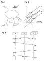
Fig.1 schematically shows a Wide Area Monitoring System, -
Fig.2 depicts basic clock relationships, and -
Fig.3 shows a message sequence chart according to the invention. - The reference symbols used in the drawings, and their meanings, are listed in summary form in the list of reference symbols. In principle, identical parts are provided with the same reference symbols in the figures.
-
-
Fig.1 shows a Wide Area Monitoring system for a power transmission network, with several Phasor Measurement Units (PMUs) installed at distributed locations. The PMU calculate phasor values and cyclically send these to a Network Control Center (NCC) over a wide area communication network. A satellite of a Global Positioning System (GPS) broadcasts global time signals. Any clock at one of the PMUs, i.e. the client or slave clock C, need to be synchronized with the clock at the NCC, i.e. the server or master clock S. -
Fig.2 depicts the clock relationships. The clock of a PMU C(t) is characterized by
where θ c is the time offset, φ C·t is the clock drift, and t denotes true time. Similarly, for the clock S(t) of the NCC,
- The clocks C(t) of the PMU must be synchronized to the clock S(t) of the NCC, i.e. the time offset x(t) of the PMU clock against the NCC clock must be estimated and then corrected at the client, where

- Here, the term y(t) denotes a frequency offset. Practical methods to obtain this offset are:
- 1. One-way GPS measurements: Both the clients and the server receive time information G(t) broadcast from a common source, in practice from a GPS satellite. The receive
times measured by the client and the server are C'(t) and S'(t), respectively, for which


By comparison of the values C(t) and G(t), it is then straightforward to obtain xCG(t) = = C(t) - G(t) and xSG(t) = S(t) - G(t). This is the usual way of synchronising PMU clocks. The signal xCG(t) controls the local PMU oscillator which generates 1 pps (one pulse per second) and e.g.10 MHz clock signals, to synchronize PMU sampling and time stamping. - 2. Common-view GPS measurements: In many applications it is not necessary or not desired to estimate xCG(t) and xSG(t) individually, but it may be sufficient to obtain the clock offset x(t) between client and server. This can be achieved by making use of the fact that the GPS broadcast signal G(t) is in their common view. For agreed GPS broadcast times G(ti), the client and server record the reception times C(ti) and S(ti), and exchange these measurements in a non time critical manner over some communication network. The difference of these measurements is

Fig.2 . Here, xG(ti) denotes the offset x(t) of C(t) with respect to S(t), as determined by cancelling-out the common GPS measurement G(ti). Kalman filtering or other averaging techniques could be used to further improve the estimation of x(t),. This common-view method is today's standard method to compare atomic clocks for the definition of the Coordinated Universal Time (UTC). - 3. Two-way measurements: Clock client and server perform and exchange time measurements in real-time over a (time critical) communication network, to directly determine the clock offset of the client. Standard two-way time synchronisation protocols are SNTP on the Internet, and IEEE 1588 for devices connected to a LAN. The essential steps are as follows, using IEEE 1588 terminology.
- (i) At time tn, the server broadcasts a Sync message with timestamp S1(tn), which is received by the client at C1(tn). Taking into account the message transmission delay dSC(t) of the Sync message from the server to the client, the following holds:

where x(t) is the offset, to be determined by the two-way method. - (ii) At client time C2(tn), the client sends a Delay_Reguest message to the server, which is received by the server at time S2(tn). The server responds with a Delay_Response message which contains the value of S2(tn). Similarly to above, with dCS(t) denoting the propagation delay of the Delay_Reguest in the reverse direction from client to server,

- (iii) The 4 measurements S1(tn), C1(tn), C2(tn), and S2(tn) are now available at the client.


where xT(tn) denotes the estimate of the true offset x(t), as obtained by the two-way measurement method at time tn. Methods such as Kalman filtering and averaging may further improve the estimation accuracy of time- and frequency offsets (x and y), given a sequence of measurements performed at times tn, t n+ 1, t n+ 2, etc. - (i) At time tn, the server broadcasts a Sync message with timestamp S1(tn), which is received by the client at C1(tn). Taking into account the message transmission delay dSC(t) of the Sync message from the server to the client, the following holds:
- This two-way method for time synchronisation relies on the communication network between the clients and server. The communication is time critical in the sense that any stochastic variation and asymmetries in the delays dSC(t) and dCS(t) affect the synchronisation accuracy.
- The detailed steps of the procedure are described in the following for a specific PMU client clock node C with clock C(t). All PMUs perform the procedure in parallel to synchronize their individual clocks to the central server clock S(t) of the server S. S is typically located at the NCC.
-
Fig.3 shows a message sequence chart of one round of the proposed procedure. - 1. The server clock S(t) is initially free-running (uncontrolled oscillator).
- 2. The client clock C(t) s initially free-running.
- 3. If GPS one-way time reception is available at the server S, it receives at time ti the GPS time G(ti), and records its reception time S(ti). It may use the GPS time to control its oscillator.
- 4. The server S broadcasts a Sync message to all clients Cs, cyclically at times tk. The message contains
- timestamp of message transmission S1(tk),
- if available from 3., reception time of the GPS time message S(ti).
- 5. C receives the Sync message and also records the message reception time C1(tk).
- 6. If GPS one-way time reception is available at the client C, it receives at time ti the GPS time G(ti), and records its reception time C(ti). If available from 4., C calculates its clock offset against S, according to the common-view method,

- 7. C sends a Delay_Request message to S. The message contains
- timestamp of message transmission C2(tn).
and can be combined with a cyclic PMU phasor data message in order to reduce the number of messages and the message overheads on the communication network.
- timestamp of message transmission C2(tn).
- 8. S receives the Delay_Request message and records the message reception time S2(tn), and responds with a Delay_Response message to C (at time tn'). The message contains
- the value of S2(tn),
- optionally the timestamp of its own transmission S1(tn').
- 9. C receives the Delay_Response message, and, if it has received S1(tn') in 8., may record the message reception time C1(tn').
- 10. C calculates its clock offset against S, as measured by the two-way method, as follows:

As an option, the newer measurement values S1(tn') and C1(tn') from 9. could be used in place or in combination with S1(tk) and C1(tk). The client also determines the quality of xT(tn), e.g. by estimating the measurement variance σ T 2. - 11. Finally, C combines the two offset measurements xG and xT into the final offset estimate x(t), taking into account their estimated qualities. For example,

The client may finally adjust its clock according to C(t) ← C(t) - x(t). The final offset estimate is formally derived as a Maximum Likelihood estimate from two independent Gaussian measurements xG and xT with variances σ G 2 and σ T 2. In the practically relevant case where the GPS-derived measurements xG are much more accurate than xT, due to the network transmission delays and jitter of the latter, i.e. σ G 2 << σ T 2, this results simply in x(t) = xG(ti). The present procedure allows a seamless or hitless transition between the two offset measurement schemes, if one fails and hence its variance increases. - 12. Update times tn, tk , and ti , and loop cyclically from step 3.
- The update of time instances ti (when GPS time measurements and offset transfer are performed), the times tk (when the server broadcasts Sync messages) and time instances tn (when the two-way measurement exchange is performed) need not be synchronous. The newest available smoothed measurements should be used in the update algorithms. The update rates of these procedures can be selected based on availability of resources such as processor time and network bandwidth. Higher rates increase accuracy of estimation, at a cost of higher processing and communication load.
- In order to accurately measure and correct the time offset x(t), the frequency offset y(t) of the clocks must also be estimated using successive time offset measurements. The basic assumption is (3), i.e. a linearly increasing clock offset, wherein quadratic models can also be envisaged.
- The message transmission delays are subject to stochastic jitter and outliers. The cyclic repetition of the described procedure allows the application of the known smoothing algorithms to improve accuracy. Also, the noise (jitter) variance can be estimated and other method to asses the measurement accuracies employed. For example, large values of the difference |Ck(tn) - Sk(tn)| are outliers indicating isolated transmission problems affecting the transmission delays, and should not be used to update the desired clock offset estimates. Recursive estimation algorithms which can interpolate between missing samples, such as temporary loss of GPS reception or outliers in the network delays, can be applied to improve performance.
-
- 1
- Phasor Measurement Unit (PMU)
- 2
- Network Control Center (NCC)
- 3
- GPS satellite
- 4
- Wide Area Communication Network
Claims (7)
- Method of estimating a time offset x between first and second stationary clocks C, S adapted to receive a global time signal G and interconnected through a communication network (4), comprising- receiving, by the first and second clock C, S, a broadcast global time signal G(ti) from a global time reference (3), and calculating, at the first clock, a common view based clock offset xG(ti) between the first and second stationary clocks based on reception times C(ti), S(ti) of the global time signal G(ti),- exchanging time-critical messages between the first and second clock C, S and calculating, at the first clock, a network based clock offset xT(tn) between the first and second stationary clocks based on transmission times S1(tk), C2(tn) and reception times C1(tk), S2(tn) of the messages, and- combining the common view based clock offset xG(ti) and the network based clock offset xT(tn) to estimate the time offset x.
- The method according to claim 1, characterized in that it comprises- estimating a quality ↑G, ↑T for the common view and network based clock offset xG(ti), xT(tn), and- combining the two clock offsets by calculating a weighted average x based on the estimated qualities ↑G, ↑T.
- The method according to claim 1, characterized in that the calculation of the common view based clock offset xG(ti) comprises- sending, by the second clock, a message comprising the reception time S(ti) of the global time signal G(ti) at the second clock to the first clock in a non-time critical manner.
- The method according to claim 1, characterized in that comprises- updating independently and repeatedly the calculation of the common view based clock offset xG(ti) and the network based clock offset xT(tn).
- The method according to claim 1, characterized in that the first clock C is a clock of a Phasor Measurement Unit (PMU) of a Wide Area Monitoring System, and that the second clock S is the clock at the Network Control Center (NCC) of the Wide Area Monitoring System.
- The method according to claim 5, characterized in that the calculation of the network based clock offset xT(tn) comprises- sending a time-critical message including PMU phasor data from the first clock C to the second clock S.
- Device with a stationary first clock C and adapted to receive a global time signal G and to exchange messages through a communication network (4), comprising- means for calculating a common view based clock offset xG(ti) between the first clock C and a second clock S based on reception times S(ti), C(ti) of the global time signal G(ti) at the location of the first and second clock C, S,- means for calculating a network based clock offset xT(tn) between the first clock C and the second clock S based on transmission times S1(tk), C2(tn) and reception times C1(tk), S2(tn) of time-critical messages exchanged between the first and second clock C, S, and- means for combining the common view based clock offset xG(ti) and the network based clock offset xT(tn) to estimate a time offset x between the first clock C and the second clock S.
Priority Applications (1)
| Application Number | Priority Date | Filing Date | Title |
|---|---|---|---|
| EP08774209A EP2174397B1 (en) | 2007-08-06 | 2008-06-23 | Estimating a time offset between stationary clocks |
Applications Claiming Priority (3)
| Application Number | Priority Date | Filing Date | Title |
|---|---|---|---|
| EP07113845A EP2023456A1 (en) | 2007-08-06 | 2007-08-06 | Estimating a time offset between stationary clocks |
| EP08774209A EP2174397B1 (en) | 2007-08-06 | 2008-06-23 | Estimating a time offset between stationary clocks |
| PCT/EP2008/057931 WO2009019067A1 (en) | 2007-08-06 | 2008-06-23 | Estimating a time offset between stationary clocks |
Publications (2)
| Publication Number | Publication Date |
|---|---|
| EP2174397A1 EP2174397A1 (en) | 2010-04-14 |
| EP2174397B1 true EP2174397B1 (en) | 2010-12-22 |
Family
ID=38926939
Family Applications (2)
| Application Number | Title | Priority Date | Filing Date |
|---|---|---|---|
| EP07113845A Withdrawn EP2023456A1 (en) | 2007-08-06 | 2007-08-06 | Estimating a time offset between stationary clocks |
| EP08774209A Active EP2174397B1 (en) | 2007-08-06 | 2008-06-23 | Estimating a time offset between stationary clocks |
Family Applications Before (1)
| Application Number | Title | Priority Date | Filing Date |
|---|---|---|---|
| EP07113845A Withdrawn EP2023456A1 (en) | 2007-08-06 | 2007-08-06 | Estimating a time offset between stationary clocks |
Country Status (8)
| Country | Link |
|---|---|
| US (1) | US7865331B2 (en) |
| EP (2) | EP2023456A1 (en) |
| CN (1) | CN101772872B (en) |
| AT (1) | ATE492930T1 (en) |
| BR (1) | BRPI0814984A2 (en) |
| DE (1) | DE602008004160D1 (en) |
| ES (1) | ES2357179T3 (en) |
| WO (1) | WO2009019067A1 (en) |
Families Citing this family (26)
| Publication number | Priority date | Publication date | Assignee | Title |
|---|---|---|---|---|
| US8139489B2 (en) * | 2008-08-06 | 2012-03-20 | International Business Machines Corporation | Robust jitter-free remote clock offset measuring method |
| US8533355B2 (en) | 2009-11-02 | 2013-09-10 | International Business Machines Corporation | Techniques for improved clock offset measuring |
| DE102010022525A1 (en) * | 2010-02-11 | 2012-05-10 | Siemens Aktiengesellschaft | Method for time synchronization in communication network for industrial automation system, involves estimating frequency ratio of reference cycle frequency to internal cycle frequency of node |
| WO2012009365A1 (en) * | 2010-07-12 | 2012-01-19 | Advanced Energy Industries, Inc. | Systems and methods for electrical power grid monitoring using loosely synchronized phasors |
| CN102004258B (en) * | 2010-09-09 | 2012-10-10 | 中国计量科学研究院 | Time frequency transfer method and receiver based on multiple global navigation satellite system (GNSS) integration |
| US8504864B2 (en) * | 2010-12-01 | 2013-08-06 | GM Global Technology Operations LLC | Data sensor coordination using time synchronization in a multi-bus controller area network system |
| JP5649505B2 (en) | 2011-04-19 | 2015-01-07 | 株式会社東芝 | Synchronous control system |
| CN102323739B (en) * | 2011-09-20 | 2014-02-05 | 郑州轻工业学院 | Multilevel time measurement and control method in synchronous clock technology |
| DE102012204084A1 (en) * | 2011-12-23 | 2013-06-27 | Rohde & Schwarz Gmbh & Co. Kg | Method and system for optimizing a short term stability of a clock |
| EP2693586B1 (en) * | 2012-07-31 | 2016-04-06 | ABB Research Ltd. | Clock synchronization for line differential protection |
| US8959381B2 (en) * | 2012-09-05 | 2015-02-17 | Khalifa University of Science, Technology, and Research | Method and system for clock offset and skew estimation |
| CN103888309B (en) * | 2012-12-20 | 2017-09-08 | 中国移动通信集团公司 | Synchronous regime monitoring method and device |
| US20150103818A1 (en) * | 2013-10-11 | 2015-04-16 | Qualcomm Incorporated | Transport and error compensation of a globally synchronized time-base |
| US9369269B2 (en) * | 2013-12-03 | 2016-06-14 | Smart Energy Instruments Inc. | Communication systems and methods for distributed power system measurement |
| US10142088B2 (en) | 2014-01-31 | 2018-11-27 | University Of North Dakota | Network clock skew estimation and calibration |
| CN104199054A (en) * | 2014-08-22 | 2014-12-10 | 北京无线电计量测试研究所 | Preprocessing method for common view data of Beidou satellite navigation system |
| CN104238352B (en) * | 2014-09-24 | 2017-07-21 | 北京市计量检测科学研究院 | The local time standard generation system and method that a kind of National primary standard is controlled |
| WO2016111816A1 (en) * | 2015-01-08 | 2016-07-14 | Sweetsense, Inc. | System and method for operating a microcomputer in sleep-mode and awake-mode with low power processing |
| CN106772463A (en) * | 2016-12-23 | 2017-05-31 | 中国电子科技集团公司第三十研究所 | A kind of time service security fuzz testing method of electric power wide area monitoring system |
| CN107483136A (en) * | 2017-08-09 | 2017-12-15 | 北京纳飞时空信息技术有限公司 | A kind of clock synchronizing method between fixed communication apparatus |
| CN107592176A (en) * | 2017-08-16 | 2018-01-16 | 清华大学 | Time and frequency synchronization method and device for networked weather radar |
| US10944818B1 (en) * | 2017-08-30 | 2021-03-09 | Amazon Technologies, Inc. | Time synchronization monitoring with client mirroring |
| US11197075B1 (en) * | 2018-12-27 | 2021-12-07 | Equinix, Inc. | Clock synchronization in a heterogeneous system |
| CN117270376A (en) * | 2021-04-12 | 2023-12-22 | 中国计量科学研究院 | Common view data generation method, receiver and time-consuming terminal |
| CN114978403B (en) * | 2022-07-29 | 2022-10-04 | 深圳市英特瑞半导体科技有限公司 | Method and device for measuring clock holding phase deviation value |
| CN115657448B (en) * | 2022-12-09 | 2023-03-28 | 电信科学技术第五研究所有限公司 | Frequency offset analysis method for clock discipline |
Family Cites Families (5)
| Publication number | Priority date | Publication date | Assignee | Title |
|---|---|---|---|---|
| US6295455B1 (en) * | 1999-06-11 | 2001-09-25 | Telefonaktiebolaget Lm Ericsson (Publ) | Methods and arrangements for locating a mobile telecommunications station |
| DE60103510T2 (en) * | 2000-03-17 | 2005-06-23 | Thomson Licensing S.A., Boulogne | METHOD AND DEVICE FOR SIMULTANEOUS RECORDING AND PLAYBACK OF TWO DIFFERENT VIDEO PROGRAMS |
| GB2388264A (en) * | 2002-01-10 | 2003-11-05 | Roke Manor Research | GPS based networked time synchronised unit |
| EP1408595B1 (en) * | 2002-10-10 | 2017-06-14 | ABB Research Ltd. | Determining parameters of an equivalent circuit representing a transmission section of an electrical network |
| US6788249B1 (en) * | 2003-07-23 | 2004-09-07 | Snaptrack Incorporated | System for setting coarse GPS time in a mobile station within an asynchronous wireless network |
-
2007
- 2007-08-06 EP EP07113845A patent/EP2023456A1/en not_active Withdrawn
-
2008
- 2008-06-23 ES ES08774209T patent/ES2357179T3/en active Active
- 2008-06-23 WO PCT/EP2008/057931 patent/WO2009019067A1/en not_active Ceased
- 2008-06-23 DE DE602008004160T patent/DE602008004160D1/en active Active
- 2008-06-23 AT AT08774209T patent/ATE492930T1/en not_active IP Right Cessation
- 2008-06-23 CN CN2008801020700A patent/CN101772872B/en active Active
- 2008-06-23 BR BRPI0814984-4A2A patent/BRPI0814984A2/en not_active IP Right Cessation
- 2008-06-23 EP EP08774209A patent/EP2174397B1/en active Active
-
2010
- 2010-02-02 US US12/698,641 patent/US7865331B2/en active Active
Also Published As
| Publication number | Publication date |
|---|---|
| US7865331B2 (en) | 2011-01-04 |
| EP2174397A1 (en) | 2010-04-14 |
| EP2023456A1 (en) | 2009-02-11 |
| CN101772872A (en) | 2010-07-07 |
| US20100138187A1 (en) | 2010-06-03 |
| ES2357179T3 (en) | 2011-04-19 |
| BRPI0814984A2 (en) | 2015-02-03 |
| ATE492930T1 (en) | 2011-01-15 |
| WO2009019067A1 (en) | 2009-02-12 |
| CN101772872B (en) | 2013-05-08 |
| DE602008004160D1 (en) | 2011-02-03 |
Similar Documents
| Publication | Publication Date | Title |
|---|---|---|
| EP2174397B1 (en) | Estimating a time offset between stationary clocks | |
| US6658025B2 (en) | Synchronization in packet-switched telecommunications system | |
| US11153838B1 (en) | Time synchronization enhancements for integrated 5G-TSN networking | |
| JP3085511B2 (en) | Reference frequency generator | |
| KR20090032306A (en) | Time synchronization system and method on the network | |
| JP2000115210A (en) | Distribution system | |
| HUP0202981A2 (en) | Methods and devices for creating list of the signal displacements from several transmitter unit, as well as, radio positioning method and system, and digital telephone network | |
| KR20170058167A (en) | Method and apparatus for synchronizing time | |
| CN120729459A (en) | Distribution network distributed measurement synchronization method and device based on Beidou satellite timing | |
| US11683772B2 (en) | Continuous synchronization of multiple radio devices to physical time | |
| US20100293243A1 (en) | method and apparatus for measuring directionally differentiated (one-way) network latency | |
| US6647026B1 (en) | Frame phase synchronous system and a method thereof | |
| EP2710761B1 (en) | Clustering apparatus and method for controlling timing | |
| US7765422B2 (en) | Method of determining a time offset estimate between a central node and a secondary node | |
| KR20120076135A (en) | Apparatus and method for controlling network timing | |
| CN106612152A (en) | Method for accurately evaluating lower bound of time offset estimator of IEEE1588 synchronous clock | |
| Shim et al. | Provisioning high-precision clock synchronization between UAVs for low latency networks | |
| Ebadi et al. | An over-the-air CFO-assisted synchronization algorithm for TDOA-based localization systems | |
| JP6674400B2 (en) | Time synchronization system and time synchronization method | |
| KR101605316B1 (en) | frequency error estimating apparatus using Rx delay in PTP | |
| JP6893070B2 (en) | Information communication system | |
| JP4535288B2 (en) | Distributed control system | |
| Calder et al. | Ultraprecise absolute time synchronization for distributed acquisition systems | |
| CN119233387B (en) | Time synchronization method, system and device between base stations based on UWB and base station | |
| KR101665924B1 (en) | Frequency offset estimation system using network time protocol time offset |
Legal Events
| Date | Code | Title | Description |
|---|---|---|---|
| PUAI | Public reference made under article 153(3) epc to a published international application that has entered the european phase |
Free format text: ORIGINAL CODE: 0009012 |
|
| 17P | Request for examination filed |
Effective date: 20091221 |
|
| AK | Designated contracting states |
Kind code of ref document: A1 Designated state(s): AT BE BG CH CY CZ DE DK EE ES FI FR GB GR HR HU IE IS IT LI LT LU LV MC MT NL NO PL PT RO SE SI SK TR |
|
| AX | Request for extension of the european patent |
Extension state: AL BA MK RS |
|
| RIN1 | Information on inventor provided before grant (corrected) |
Inventor name: DZUNG, DACFEY Inventor name: LARSSON, MATS |
|
| GRAP | Despatch of communication of intention to grant a patent |
Free format text: ORIGINAL CODE: EPIDOSNIGR1 |
|
| GRAS | Grant fee paid |
Free format text: ORIGINAL CODE: EPIDOSNIGR3 |
|
| DAX | Request for extension of the european patent (deleted) | ||
| GRAA | (expected) grant |
Free format text: ORIGINAL CODE: 0009210 |
|
| AK | Designated contracting states |
Kind code of ref document: B1 Designated state(s): AT BE BG CH CY CZ DE DK EE ES FI FR GB GR HR HU IE IS IT LI LT LU LV MC MT NL NO PL PT RO SE SI SK TR |
|
| REG | Reference to a national code |
Ref country code: GB Ref legal event code: FG4D |
|
| REG | Reference to a national code |
Ref country code: CH Ref legal event code: EP |
|
| REG | Reference to a national code |
Ref country code: IE Ref legal event code: FG4D |
|
| REF | Corresponds to: |
Ref document number: 602008004160 Country of ref document: DE Date of ref document: 20110203 Kind code of ref document: P |
|
| REG | Reference to a national code |
Ref country code: DE Ref legal event code: R096 Ref document number: 602008004160 Country of ref document: DE Effective date: 20110203 |
|
| REG | Reference to a national code |
Ref country code: SE Ref legal event code: TRGR |
|
| REG | Reference to a national code |
Ref country code: NL Ref legal event code: VDEP Effective date: 20101222 |
|
| REG | Reference to a national code |
Ref country code: ES Ref legal event code: FG2A Ref document number: 2357179 Country of ref document: ES Kind code of ref document: T3 Effective date: 20110419 |
|
| PG25 | Lapsed in a contracting state [announced via postgrant information from national office to epo] |
Ref country code: LT Free format text: LAPSE BECAUSE OF FAILURE TO SUBMIT A TRANSLATION OF THE DESCRIPTION OR TO PAY THE FEE WITHIN THE PRESCRIBED TIME-LIMIT Effective date: 20101222 |
|
| LTIE | Lt: invalidation of european patent or patent extension |
Effective date: 20101222 |
|
| PG25 | Lapsed in a contracting state [announced via postgrant information from national office to epo] |
Ref country code: FI Free format text: LAPSE BECAUSE OF FAILURE TO SUBMIT A TRANSLATION OF THE DESCRIPTION OR TO PAY THE FEE WITHIN THE PRESCRIBED TIME-LIMIT Effective date: 20101222 Ref country code: CY Free format text: LAPSE BECAUSE OF FAILURE TO SUBMIT A TRANSLATION OF THE DESCRIPTION OR TO PAY THE FEE WITHIN THE PRESCRIBED TIME-LIMIT Effective date: 20101222 Ref country code: AT Free format text: LAPSE BECAUSE OF FAILURE TO SUBMIT A TRANSLATION OF THE DESCRIPTION OR TO PAY THE FEE WITHIN THE PRESCRIBED TIME-LIMIT Effective date: 20101222 Ref country code: BG Free format text: LAPSE BECAUSE OF FAILURE TO SUBMIT A TRANSLATION OF THE DESCRIPTION OR TO PAY THE FEE WITHIN THE PRESCRIBED TIME-LIMIT Effective date: 20110322 Ref country code: LV Free format text: LAPSE BECAUSE OF FAILURE TO SUBMIT A TRANSLATION OF THE DESCRIPTION OR TO PAY THE FEE WITHIN THE PRESCRIBED TIME-LIMIT Effective date: 20101222 Ref country code: SI Free format text: LAPSE BECAUSE OF FAILURE TO SUBMIT A TRANSLATION OF THE DESCRIPTION OR TO PAY THE FEE WITHIN THE PRESCRIBED TIME-LIMIT Effective date: 20101222 Ref country code: HR Free format text: LAPSE BECAUSE OF FAILURE TO SUBMIT A TRANSLATION OF THE DESCRIPTION OR TO PAY THE FEE WITHIN THE PRESCRIBED TIME-LIMIT Effective date: 20101222 |
|
| PG25 | Lapsed in a contracting state [announced via postgrant information from national office to epo] |
Ref country code: CZ Free format text: LAPSE BECAUSE OF FAILURE TO SUBMIT A TRANSLATION OF THE DESCRIPTION OR TO PAY THE FEE WITHIN THE PRESCRIBED TIME-LIMIT Effective date: 20101222 Ref country code: GR Free format text: LAPSE BECAUSE OF FAILURE TO SUBMIT A TRANSLATION OF THE DESCRIPTION OR TO PAY THE FEE WITHIN THE PRESCRIBED TIME-LIMIT Effective date: 20110323 Ref country code: BE Free format text: LAPSE BECAUSE OF FAILURE TO SUBMIT A TRANSLATION OF THE DESCRIPTION OR TO PAY THE FEE WITHIN THE PRESCRIBED TIME-LIMIT Effective date: 20101222 Ref country code: PT Free format text: LAPSE BECAUSE OF FAILURE TO SUBMIT A TRANSLATION OF THE DESCRIPTION OR TO PAY THE FEE WITHIN THE PRESCRIBED TIME-LIMIT Effective date: 20110422 Ref country code: IS Free format text: LAPSE BECAUSE OF FAILURE TO SUBMIT A TRANSLATION OF THE DESCRIPTION OR TO PAY THE FEE WITHIN THE PRESCRIBED TIME-LIMIT Effective date: 20110422 Ref country code: NO Free format text: LAPSE BECAUSE OF FAILURE TO SUBMIT A TRANSLATION OF THE DESCRIPTION OR TO PAY THE FEE WITHIN THE PRESCRIBED TIME-LIMIT Effective date: 20110322 Ref country code: EE Free format text: LAPSE BECAUSE OF FAILURE TO SUBMIT A TRANSLATION OF THE DESCRIPTION OR TO PAY THE FEE WITHIN THE PRESCRIBED TIME-LIMIT Effective date: 20101222 |
|
| PG25 | Lapsed in a contracting state [announced via postgrant information from national office to epo] |
Ref country code: NL Free format text: LAPSE BECAUSE OF FAILURE TO SUBMIT A TRANSLATION OF THE DESCRIPTION OR TO PAY THE FEE WITHIN THE PRESCRIBED TIME-LIMIT Effective date: 20101222 Ref country code: RO Free format text: LAPSE BECAUSE OF FAILURE TO SUBMIT A TRANSLATION OF THE DESCRIPTION OR TO PAY THE FEE WITHIN THE PRESCRIBED TIME-LIMIT Effective date: 20101222 Ref country code: SK Free format text: LAPSE BECAUSE OF FAILURE TO SUBMIT A TRANSLATION OF THE DESCRIPTION OR TO PAY THE FEE WITHIN THE PRESCRIBED TIME-LIMIT Effective date: 20101222 Ref country code: PL Free format text: LAPSE BECAUSE OF FAILURE TO SUBMIT A TRANSLATION OF THE DESCRIPTION OR TO PAY THE FEE WITHIN THE PRESCRIBED TIME-LIMIT Effective date: 20101222 |
|
| PLBE | No opposition filed within time limit |
Free format text: ORIGINAL CODE: 0009261 |
|
| STAA | Information on the status of an ep patent application or granted ep patent |
Free format text: STATUS: NO OPPOSITION FILED WITHIN TIME LIMIT |
|
| PG25 | Lapsed in a contracting state [announced via postgrant information from national office to epo] |
Ref country code: DK Free format text: LAPSE BECAUSE OF FAILURE TO SUBMIT A TRANSLATION OF THE DESCRIPTION OR TO PAY THE FEE WITHIN THE PRESCRIBED TIME-LIMIT Effective date: 20101222 |
|
| 26N | No opposition filed |
Effective date: 20110923 |
|
| PG25 | Lapsed in a contracting state [announced via postgrant information from national office to epo] |
Ref country code: MT Free format text: LAPSE BECAUSE OF FAILURE TO SUBMIT A TRANSLATION OF THE DESCRIPTION OR TO PAY THE FEE WITHIN THE PRESCRIBED TIME-LIMIT Effective date: 20101222 |
|
| REG | Reference to a national code |
Ref country code: DE Ref legal event code: R097 Ref document number: 602008004160 Country of ref document: DE Effective date: 20110923 |
|
| REG | Reference to a national code |
Ref country code: IE Ref legal event code: MM4A |
|
| PG25 | Lapsed in a contracting state [announced via postgrant information from national office to epo] |
Ref country code: IE Free format text: LAPSE BECAUSE OF NON-PAYMENT OF DUE FEES Effective date: 20110623 |
|
| REG | Reference to a national code |
Ref country code: CH Ref legal event code: PL |
|
| REG | Reference to a national code |
Ref country code: CH Ref legal event code: PL |
|
| PG25 | Lapsed in a contracting state [announced via postgrant information from national office to epo] |
Ref country code: CH Free format text: LAPSE BECAUSE OF NON-PAYMENT OF DUE FEES Effective date: 20120630 Ref country code: MC Free format text: LAPSE BECAUSE OF NON-PAYMENT OF DUE FEES Effective date: 20110630 Ref country code: LI Free format text: LAPSE BECAUSE OF NON-PAYMENT OF DUE FEES Effective date: 20120630 |
|
| PG25 | Lapsed in a contracting state [announced via postgrant information from national office to epo] |
Ref country code: LU Free format text: LAPSE BECAUSE OF NON-PAYMENT OF DUE FEES Effective date: 20110623 |
|
| PG25 | Lapsed in a contracting state [announced via postgrant information from national office to epo] |
Ref country code: TR Free format text: LAPSE BECAUSE OF FAILURE TO SUBMIT A TRANSLATION OF THE DESCRIPTION OR TO PAY THE FEE WITHIN THE PRESCRIBED TIME-LIMIT Effective date: 20101222 |
|
| PG25 | Lapsed in a contracting state [announced via postgrant information from national office to epo] |
Ref country code: HU Free format text: LAPSE BECAUSE OF FAILURE TO SUBMIT A TRANSLATION OF THE DESCRIPTION OR TO PAY THE FEE WITHIN THE PRESCRIBED TIME-LIMIT Effective date: 20101222 |
|
| REG | Reference to a national code |
Ref country code: FR Ref legal event code: PLFP Year of fee payment: 9 |
|
| PGFP | Annual fee paid to national office [announced via postgrant information from national office to epo] |
Ref country code: GB Payment date: 20160621 Year of fee payment: 9 Ref country code: ES Payment date: 20160614 Year of fee payment: 9 |
|
| PGFP | Annual fee paid to national office [announced via postgrant information from national office to epo] |
Ref country code: SE Payment date: 20160620 Year of fee payment: 9 |
|
| PGFP | Annual fee paid to national office [announced via postgrant information from national office to epo] |
Ref country code: IT Payment date: 20160628 Year of fee payment: 9 |
|
| REG | Reference to a national code |
Ref country code: FR Ref legal event code: PLFP Year of fee payment: 10 |
|
| REG | Reference to a national code |
Ref country code: SE Ref legal event code: EUG |
|
| GBPC | Gb: european patent ceased through non-payment of renewal fee |
Effective date: 20170623 |
|
| PG25 | Lapsed in a contracting state [announced via postgrant information from national office to epo] |
Ref country code: SE Free format text: LAPSE BECAUSE OF NON-PAYMENT OF DUE FEES Effective date: 20170624 |
|
| PG25 | Lapsed in a contracting state [announced via postgrant information from national office to epo] |
Ref country code: GB Free format text: LAPSE BECAUSE OF NON-PAYMENT OF DUE FEES Effective date: 20170623 |
|
| PG25 | Lapsed in a contracting state [announced via postgrant information from national office to epo] |
Ref country code: IT Free format text: LAPSE BECAUSE OF NON-PAYMENT OF DUE FEES Effective date: 20170623 |
|
| REG | Reference to a national code |
Ref country code: FR Ref legal event code: PLFP Year of fee payment: 11 |
|
| REG | Reference to a national code |
Ref country code: ES Ref legal event code: FD2A Effective date: 20181112 |
|
| PG25 | Lapsed in a contracting state [announced via postgrant information from national office to epo] |
Ref country code: ES Free format text: LAPSE BECAUSE OF NON-PAYMENT OF DUE FEES Effective date: 20170624 |
|
| REG | Reference to a national code |
Ref country code: DE Ref legal event code: R081 Ref document number: 602008004160 Country of ref document: DE Owner name: HITACHI ENERGY SWITZERLAND AG, CH Free format text: FORMER OWNER: ABB RESEARCH LTD., ZUERICH, CH Ref country code: DE Ref legal event code: R082 Ref document number: 602008004160 Country of ref document: DE Representative=s name: ZIMMERMANN & PARTNER PATENTANWAELTE MBB, DE Ref country code: DE Ref legal event code: R081 Ref document number: 602008004160 Country of ref document: DE Owner name: ABB SCHWEIZ AG, CH Free format text: FORMER OWNER: ABB RESEARCH LTD., ZUERICH, CH Ref country code: DE Ref legal event code: R081 Ref document number: 602008004160 Country of ref document: DE Owner name: ABB POWER GRIDS SWITZERLAND AG, CH Free format text: FORMER OWNER: ABB RESEARCH LTD., ZUERICH, CH Ref country code: DE Ref legal event code: R082 Ref document number: 602008004160 Country of ref document: DE Representative=s name: DENNEMEYER & ASSOCIATES S.A., DE |
|
| REG | Reference to a national code |
Ref country code: DE Ref legal event code: R081 Ref document number: 602008004160 Country of ref document: DE Owner name: HITACHI ENERGY SWITZERLAND AG, CH Free format text: FORMER OWNER: ABB SCHWEIZ AG, BADEN, CH Ref country code: DE Ref legal event code: R082 Ref document number: 602008004160 Country of ref document: DE Representative=s name: DENNEMEYER & ASSOCIATES RECHTSANWALTSGESELLSCH, DE Ref country code: DE Ref legal event code: R081 Ref document number: 602008004160 Country of ref document: DE Owner name: HITACHI ENERGY LTD, CH Free format text: FORMER OWNER: ABB SCHWEIZ AG, BADEN, CH Ref country code: DE Ref legal event code: R082 Ref document number: 602008004160 Country of ref document: DE Representative=s name: DENNEMEYER & ASSOCIATES S.A., DE Ref country code: DE Ref legal event code: R081 Ref document number: 602008004160 Country of ref document: DE Owner name: ABB POWER GRIDS SWITZERLAND AG, CH Free format text: FORMER OWNER: ABB SCHWEIZ AG, BADEN, CH |
|
| REG | Reference to a national code |
Ref country code: DE Ref legal event code: R081 Ref document number: 602008004160 Country of ref document: DE Owner name: HITACHI ENERGY SWITZERLAND AG, CH Free format text: FORMER OWNER: ABB POWER GRIDS SWITZERLAND AG, BADEN, CH Ref country code: DE Ref legal event code: R081 Ref document number: 602008004160 Country of ref document: DE Owner name: HITACHI ENERGY LTD, CH Free format text: FORMER OWNER: ABB POWER GRIDS SWITZERLAND AG, BADEN, CH |
|
| P01 | Opt-out of the competence of the unified patent court (upc) registered |
Effective date: 20230527 |
|
| REG | Reference to a national code |
Ref country code: DE Ref legal event code: R082 Ref document number: 602008004160 Country of ref document: DE Representative=s name: DENNEMEYER & ASSOCIATES RECHTSANWALTSGESELLSCH, DE Ref country code: DE Ref legal event code: R082 Ref document number: 602008004160 Country of ref document: DE Representative=s name: DENNEMEYER & ASSOCIATES S.A., DE Ref country code: DE Ref legal event code: R081 Ref document number: 602008004160 Country of ref document: DE Owner name: HITACHI ENERGY LTD, CH Free format text: FORMER OWNER: HITACHI ENERGY SWITZERLAND AG, BADEN, CH |
|
| REG | Reference to a national code |
Ref country code: DE Ref legal event code: R082 Ref document number: 602008004160 Country of ref document: DE Representative=s name: DENNEMEYER & ASSOCIATES RECHTSANWALTSGESELLSCH, DE |
|
| PGFP | Annual fee paid to national office [announced via postgrant information from national office to epo] |
Ref country code: DE Payment date: 20250618 Year of fee payment: 18 |
|
| PGFP | Annual fee paid to national office [announced via postgrant information from national office to epo] |
Ref country code: FR Payment date: 20250624 Year of fee payment: 18 |