EP2174094B1 - Hydraulische überwachungseinheit - Google Patents
Hydraulische überwachungseinheit Download PDFInfo
- Publication number
- EP2174094B1 EP2174094B1 EP08786075.5A EP08786075A EP2174094B1 EP 2174094 B1 EP2174094 B1 EP 2174094B1 EP 08786075 A EP08786075 A EP 08786075A EP 2174094 B1 EP2174094 B1 EP 2174094B1
- Authority
- EP
- European Patent Office
- Prior art keywords
- temperature
- measurement areas
- liquid
- previous
- measurement
- Prior art date
- Legal status (The legal status is an assumption and is not a legal conclusion. Google has not performed a legal analysis and makes no representation as to the accuracy of the status listed.)
- Active
Links
- 238000012544 monitoring process Methods 0.000 title description 5
- 238000005259 measurement Methods 0.000 claims description 35
- 239000007788 liquid Substances 0.000 claims description 19
- 239000000523 sample Substances 0.000 claims description 14
- 238000000034 method Methods 0.000 claims description 12
- XLYOFNOQVPJJNP-UHFFFAOYSA-N water Substances O XLYOFNOQVPJJNP-UHFFFAOYSA-N 0.000 claims description 11
- 230000017525 heat dissipation Effects 0.000 claims description 7
- 238000010438 heat treatment Methods 0.000 claims description 7
- 239000013307 optical fiber Substances 0.000 claims description 3
- 239000012071 phase Substances 0.000 claims 4
- 238000009529 body temperature measurement Methods 0.000 claims 1
- 239000007791 liquid phase Substances 0.000 claims 1
- 239000007790 solid phase Substances 0.000 claims 1
- 239000007787 solid Substances 0.000 description 8
- 230000003628 erosive effect Effects 0.000 description 2
- 239000012530 fluid Substances 0.000 description 2
- 239000000463 material Substances 0.000 description 2
- 238000000691 measurement method Methods 0.000 description 2
- 238000012986 modification Methods 0.000 description 2
- 230000004048 modification Effects 0.000 description 2
- 238000012545 processing Methods 0.000 description 2
- 230000035945 sensitivity Effects 0.000 description 2
- 238000006424 Flood reaction Methods 0.000 description 1
- 230000003247 decreasing effect Effects 0.000 description 1
- 239000006185 dispersion Substances 0.000 description 1
- 230000000694 effects Effects 0.000 description 1
- 238000010292 electrical insulation Methods 0.000 description 1
- 230000007613 environmental effect Effects 0.000 description 1
- 230000008595 infiltration Effects 0.000 description 1
- 238000001764 infiltration Methods 0.000 description 1
- 239000012212 insulator Substances 0.000 description 1
- 239000010410 layer Substances 0.000 description 1
- 238000004519 manufacturing process Methods 0.000 description 1
- 238000007747 plating Methods 0.000 description 1
- 238000011160 research Methods 0.000 description 1
- 239000013049 sediment Substances 0.000 description 1
- 239000000758 substrate Substances 0.000 description 1
- 239000002344 surface layer Substances 0.000 description 1
- 239000000725 suspension Substances 0.000 description 1
Images


Classifications
-
- G—PHYSICS
- G01—MEASURING; TESTING
- G01F—MEASURING VOLUME, VOLUME FLOW, MASS FLOW OR LIQUID LEVEL; METERING BY VOLUME
- G01F23/00—Indicating or measuring liquid level or level of fluent solid material, e.g. indicating in terms of volume or indicating by means of an alarm
- G01F23/22—Indicating or measuring liquid level or level of fluent solid material, e.g. indicating in terms of volume or indicating by means of an alarm by measuring physical variables, other than linear dimensions, pressure or weight, dependent on the level to be measured, e.g. by difference of heat transfer of steam or water
Definitions
- the present invention refers to a hydraulic monitoring unit, suitable for detecting the position of the solid-liquid and liquid-aeriform interfaces, for example to evaluate the condition of the piers that support river bridges or, more in general to monitor the phenomena of raising-lowering of the river bed.
- the monitoring of the position of such interfaces is particularly important in the case of watercourses subject to rapid variations in flow rate: sudden increases in flow rate, for example due to heavy rain, can generate erosion phenomena at the base of river piers, with consequent decrease in the useful load capacity of the bridge they support, increasing the risk of collapse.
- a first methodology for measuring such a position involves an echo sounder: by measuring the time needed for an acoustic signal to come back after being reflected from the bed, it is possible to determine the depth of the river; this system however, has some criticalities, and in particular the need for accurate assembly and armour-plating to withstand the stresses and to avoid potential obstructions caused by the materials transported by the currents, as well as the possibility of significant noise levels and possible measurement errors due to dynamic fluid disturbance (turbulence, bubbles, transported material).
- the echo sounders must also be oriented so as to not sense the presence of the structure that they are monitoring and, therefore, they do not allow the bed to be detected in the positions immediately adjacent to the structure itself.
- a second methodology uses a temperature profile sounder, which measures the temperatures at different depths. This system takes advantage of the fact that, normally, the water temperature is different from those of the surrounding ground and air.
- Temperature profile sounders are relatively simple to install, but can be unreliable, for example in the case of thermal inversion in the water, or if - for example in winter - it is impossible to notice any difference between the temperature of the air and of that of the water; moreover, since at the solid-liquid interface of a river the ground is soaked in water, it is not always possible to determine the position of such an interface with adequate precision. Moreover, such measurement methods, generally based upon thermocouples, require complex electrical insulation systems when immersed in water.
- a third methodology uses an apparatus made of a powered heater element and temperature sensors positioned on one or both sides of a single rigid or a flexible substrate.
- Various parallel and serial configurations of thermocouples are used to measure the temperature along a heater. Simultaneous measurements from all the temperature sensors, before and after heat is applied, are used to generate accurate temperature profiles for the entire heater. Different features of the temperature profiles will determine accurately the liquid level, liquid temperature and other liquid properties.
- a fourth methodology uses a measuring instrument including a U-shaped probe that senses temperature for sensing the level of a liquid in a tank.
- a main probe unit has first and second legs disposed in a side-by-side, parallel relationship and a heater cable is contained within and along the length of the first leg.
- Heated sensors are disposed inside the first leg in positions proximate to the heater cable for sensing temperatures at a plurality of positions along the first leg, and non-heated sensors are disposed in the second leg for sensing temperatures at a plurality of positions along the second leg.
- An electrical circuit is connected to the heated temperature sensors and the non-heated temperature sensors for producing at least one signal indicating the temperatures of the heated sensors and preferably indicating the temperatures of the heated sensors relative to the non-heated sensors.
- the purpose of the present invention is that of making a device which is even more precise and reliable than those known in the prior art.
- it is the intended to at least partially mitigate the drawbacks of the most common methods, due to the large bulk of the components and to their sensitivity to humidity, to the sensitivity of the measurement to disturbance induced by the current during floods (turbulence, bubbles, floating debris, sediment in suspension), and to the drift typical of electronic components.
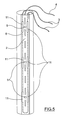
- the measurement device is globally indicated with 1.
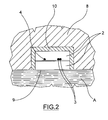
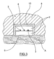
- the device 1 is represented applied onto the pier of a bridge; in figures 2 , 3 and 4 , the water medium, representing the water of a river, is indicated with the letter A.
- the device 1 comprises a support 2, heat generating means 3, for example electrical resistances, and a temperature probe 4, on which a plurality of measurement areas 5 are made, spaced apart from one another.
- the support 2 has a portion of its own surface which is not thermally insulated from the external environment, i.e. the medium in which it is immersed; in the embodiments represented in the figures, such a non-thermally insulated surface is indicated with 9; consequently the other surfaces are coated with a thermal insulator 10.
- the support 2 comprises a sandwich structure inside of which the heat generating means 3 and the temperature probe 4 are inserted.
- the temperature probe 4 comprises an optical fibre for measuring the temperature for example comprising Bragg lattices 6 within, which define the measurement areas 5.
- the operation of the temperature probe 4 with Bragg lattices 6 is as follows: through a luminous beam of a suitable wavelength it is possible to determine whether the Bragg lattice 6 has undergone deformations compared to a known reference configuration, and therefore calculate the temperature of the optical fibre (or rather of the temperature probe 4) at the measurement area 5.
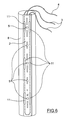
- the heat generating means can be made for example with a cable comprising heating portions 11, in which most of the heat production occurs, alternating with portions having low heat dissipation; the heating portions 11 can advantageously be arranged at the measurement areas 5. In this way the consumption of the device 1 is reduced to the minimum necessary.
- the support 2 is moreover connected to suitable processing means, for measuring the temperature in the measurement area 5; for the purpose of the present invention the physical position of such processing means is not relevant: they can be arranged either completely in the proximity of the device 1, or in a distributed way, at least partially in a remote position.
- the device 1 as previously described must be arranged across the interfaces the position of which one wishes to measure. For example, should one wish to measure the solid-liquid and liquid-aeriform interfaces of a watercourse, the device 1 can be fixed for example to a supporting pier 8 of a bridge, so that a substantial portion of the support 2 is immersed in each of the solid, liquid and aeriform media.
- a substantial portion it is meant a portion comprising one or more measurement areas 5.
- the heat generating means 3 are energized, so as to increase the temperature near each measurement area 5. In this way, since the heat exchange coefficient between the device 1 and each of the three solid, liquid and aeriform media is different, the heating produced by the heat generating means 3 will have different effects in each means and the temperature measured will therefore be different.
- the temperature measured will for example be at its minimum in the liquid medium, where the device, immersed into a liquid current with a relatively low temperature, will rapidly give its heat away to the flowing liquid.
- the measured temperature in the solid medium on the other hand, where the heat exchange coefficient substantially coincides with the heat exchange coefficient of the solid medium itself, will certainly be greater, with an abrupt increase of the temperature right at the solid-liquid interface.
- the spatial variation of the heat exchange coefficient will be made milder by phenomena such as movement of the upper layers of the solid medium and/or the infiltration of the liquid medium inside the surface layers of the solid medium.
- the variation in the heat dissipation coefficient is in any case sufficiently clear so as to allow a sufficiently precise measurement of the position of the interface.
- the temperature measured at the measurement areas 5 exposed to air will be higher than that measured at the measurement areas 5 immersed into water, due to the different characteristics of heat conducting properties of the two fluids.
- the position of the liquid-aeriform interface can also be determined at an abrupt variation in the temperature profile thus obtained.
- the temperature measured depends on both the heat exchange coefficient and on the difference in temperature between the outside temperature and the temperature of the heat generating means 3, it will be possible to adapt the operation of the device 1 to different environmental conditions, for example increasing or decreasing the power dispersed by the heat generating means 3 to avoid two different measuring points relative to two different media (e.g. solid, liquid or aeriform) accidentally having the same temperature value, because of a particular combination of temperature difference and heat exchange coefficient.
- two different media e.g. solid, liquid or aeriform
- the power supplied to the heat generating means 3 can therefore be selected so that determining the position of the interfaces is not influenced by the small natural temperature variations of each medium (for example, the temperature of the water of a river can vary by 0.1°C in the space of twenty-four hours).
- One or more measuring points are foreseen in one, in two or in all the different media, wherein there is no heat dissipation, so as to have a reference point against which to assess the reading of the measurement areas 5.
- the embodiment of figure 6 is an example of this arrangement: in it, the heat generating means 3 generate heat only near to some measurement areas 5; more precisely the measurement areas 5 are alternatively free of heating portions 11 and close to heating portions 11 of the heat generating means.
- a preferred embodiment of the present invention foresees that the heat generating means 3 be supplied with a power equal to about 0.5 W/m.
- the distance D between the measurement areas determines the spatial resolution of the device 1 according to the present invention.
- the present invention is particularly suitable for determining, also remotely, the variation in the level and in the position of the river beds, in particular for the research and the monitoring of erosion in piers of bridges.
- a plurality of devices around a pier 8, to monitor the variation in position of the interface depending on the position compared to the current of the river; or it is possible to place one or more devices on some or onto all the piers; the devices can be placed linearly onto the piers, into a U shape or into a spiral (fully or else just partially), with advantages that a man skilled in the art would immediately understand.
- the present device could also be made with two temperature probes fixed, for example parallel to one other, on the same support 2, or with a first temperature probe fixed on the support 2 and a second temperature probe substantially thermally independent from the first but physically arranged near to it.
- the second probe could for example be inserted directly into each means, so as to provide a reference reading with which to evaluate the temperature dispersion more precisely.
Landscapes
- Physics & Mathematics (AREA)
- Thermal Sciences (AREA)
- Fluid Mechanics (AREA)
- General Physics & Mathematics (AREA)
- Testing Or Calibration Of Command Recording Devices (AREA)
- Length Measuring Devices With Unspecified Measuring Means (AREA)
- Fluid-Pressure Circuits (AREA)
- Investigating Or Analyzing Materials Using Thermal Means (AREA)
Claims (8)
- Vorrichtung (1) zum Messen der Lage der Fest-flüssig- und Flüssig-gasförmig-Grenzflächen in strömendem Wasser,
umfassend mindestens einen im Wesentlichen längslaufenden und zum Anordnen entlang dem zu messenden Profil geeigneten Träger (2), entlang dem eine Vielzahl von Messbereichen (5) definiert ist; Mittel (3, 5), die zum Bestimmen der örtlichen Wärmeabgabe in jedem der Messbereiche (5) geeignet sind;
wobei diese Messbereiche (5) Temperaturmessbereiche sind, die auf mindestens einem Temperaturfühler (4) ausgeführt sind, wobei dieser Temperaturfühler (4) in dem Träger (2) enthalten ist; wobei die Vorrichtung ferner Wärmeerzeugungsmittel (3) umfasst, die geeignet sind, die Temperatur in der Nähe der Messbereiche (5) zu erhöhen; dadurch gekennzeichnet, dass diese Vorrichtung dazu gestaltet ist, an einem tragenden Pfeiler einer Brücke befestigt zu werden, und der Temperaturfühler (4) einen Lichtwellenleiter zum Messen der Temperatur umfasst, und dadurch, dass die Wärmeerzeugungsmittel (3) Heizabschnitte (11) umfassen, die sich mit Abschnitten mit einer geringen Wärmeabgabe abwechseln, wobei einige der Messbereiche (5) in der Nähe der Heizabschnitte (11) angeordnet sind. - Vorrichtung (1) nach dem vorhergehenden Anspruch, bei der die Messbereiche (5) Bereiche sind, in denen sich ein Bragg-Gitter (6) befindet.
- Vorrichtung (1) nach dem vorhergehenden Anspruch, bei der der Abstand (D) zwischen zwei aufeinanderfolgenden Messbereichen (5) kleiner als 3 Meter ist.
- Vorrichtung (1) nach dem vorhergehenden Anspruch, bei der die Wärmeerzeugungsmittel (3) einen Widerstand umfassen.
- Verfahren zum Bestimmen der Lage von einer oder mehreren Grenzflächen zwischen zwei Phasen, wobei diese Phasen aus der Gruppe ausgewählt sind, die aus einer Festphase, einer Flüssigphase und einer Gasphase besteht, wobei dieses Verfahren die folgenden Schritte umfasst:- Anordnen einer Vorrichtung (1) nach einem der vorhergehenden Ansprüche entlang einer Richtung, die quer zu der Grenzfläche verläuft, deren Lage gemessen werden soll, so dass die Vorrichtung (1) die Grenzfläche kreuzt;- wobei einer oder mehrere der Messbereiche (5) in jede der Phasen eingetaucht sind, welche diese Grenzfläche bilden;- Messen der Temperatur in diesen Messbereichen (5).
- Verfahren nach dem vorhergehenden Anspruch, das den Schritt des örtlichen Erhöhens der Temperatur in der Nähe der Messbereiche (5) umfasst.
- Verfahren nach dem vorhergehenden Anspruch, das den Schritt des Bestimmens der Wärmeabgabewerte von jedem Messbereich (5) auf der Grundlage der gemessenen Temperaturwerte umfasst.
- Verfahren nach dem vorhergehenden Anspruch, das den Schritt des Bestimmens der Lage der Fest-flüssig- und Flüssig-gasförmig-Grenzflächen anhand der Wärmeabgabewerte von jedem Messbereich (5) umfasst.
Applications Claiming Priority (2)
| Application Number | Priority Date | Filing Date | Title |
|---|---|---|---|
| IT001506A ITMI20071506A1 (it) | 2007-07-26 | 2007-07-26 | Impianto di monitoraggio idraulico. |
| PCT/EP2008/059075 WO2009013151A1 (en) | 2007-07-26 | 2008-07-11 | Hydraulic monitoring unit |
Publications (2)
| Publication Number | Publication Date |
|---|---|
| EP2174094A1 EP2174094A1 (de) | 2010-04-14 |
| EP2174094B1 true EP2174094B1 (de) | 2014-08-27 |
Family
ID=39791503
Family Applications (1)
| Application Number | Title | Priority Date | Filing Date |
|---|---|---|---|
| EP08786075.5A Active EP2174094B1 (de) | 2007-07-26 | 2008-07-11 | Hydraulische überwachungseinheit |
Country Status (4)
| Country | Link |
|---|---|
| US (1) | US8365593B2 (de) |
| EP (1) | EP2174094B1 (de) |
| IT (1) | ITMI20071506A1 (de) |
| WO (1) | WO2009013151A1 (de) |
Families Citing this family (4)
| Publication number | Priority date | Publication date | Assignee | Title |
|---|---|---|---|---|
| DE102008014739B3 (de) | 2008-03-18 | 2009-11-19 | Siemens Aktiengesellschaft | Vorrichtung zur Leckageerkennung auf einem Schiff |
| TWI392786B (zh) * | 2009-09-16 | 2013-04-11 | 財團法人國家實驗研究院 | Monitoring System of Bridge Pile Bed Height |
| CN102650606A (zh) * | 2012-05-03 | 2012-08-29 | 大连理工大学 | 一种流体介质界面的光纤传感检测装置及方法 |
| US9360380B2 (en) * | 2012-05-09 | 2016-06-07 | University Of Idaho | Method and apparatus for monitoring waterbed environment using temperature measurements |
Citations (1)
| Publication number | Priority date | Publication date | Assignee | Title |
|---|---|---|---|---|
| WO1991006833A1 (en) * | 1989-11-02 | 1991-05-16 | Haugstad Kjell M | Method and measuring device for determining and monitoring of interface areas in at least two different media |
Family Cites Families (5)
| Publication number | Priority date | Publication date | Assignee | Title |
|---|---|---|---|---|
| US4603580A (en) * | 1985-02-20 | 1986-08-05 | Scandpower, Inc. | Unicable liquid level sensing system |
| US4785665A (en) | 1987-01-16 | 1988-11-22 | Mcculloch Reg W | Measuring instrument that senses heat transfer along a probe |
| FR2766266A1 (fr) * | 1997-07-16 | 1999-01-22 | Bertin & Cie | Dispositif de detection d'une interface gaz-liquide et de mesure de la temperature |
| US20050126282A1 (en) | 2003-12-16 | 2005-06-16 | Josef Maatuk | Liquid sensor and ice detector |
| US7392691B1 (en) * | 2005-10-20 | 2008-07-01 | Sierra Lobo, Inc. | Method and apparatus for detecting the level of a liquid |
-
2007
- 2007-07-26 IT IT001506A patent/ITMI20071506A1/it unknown
-
2008
- 2008-07-11 US US12/670,315 patent/US8365593B2/en not_active Expired - Fee Related
- 2008-07-11 WO PCT/EP2008/059075 patent/WO2009013151A1/en not_active Ceased
- 2008-07-11 EP EP08786075.5A patent/EP2174094B1/de active Active
Patent Citations (1)
| Publication number | Priority date | Publication date | Assignee | Title |
|---|---|---|---|---|
| WO1991006833A1 (en) * | 1989-11-02 | 1991-05-16 | Haugstad Kjell M | Method and measuring device for determining and monitoring of interface areas in at least two different media |
Also Published As
| Publication number | Publication date |
|---|---|
| US8365593B2 (en) | 2013-02-05 |
| EP2174094A1 (de) | 2010-04-14 |
| WO2009013151A1 (en) | 2009-01-29 |
| ITMI20071506A1 (it) | 2009-01-27 |
| US20100206067A1 (en) | 2010-08-19 |
Similar Documents
| Publication | Publication Date | Title |
|---|---|---|
| US9500554B2 (en) | Method and system for detecting a leak in a pipeline | |
| EP2979066B1 (de) | System und verfahren zur identifizierung des füllstandes oder schnittstellen von medien in einem behälter | |
| US8746968B2 (en) | Microsensor produced in microsystem technologies for the measurement and/or detection of fouling | |
| KR20150064173A (ko) | 매립된 장치 주변의 토양 부식을 모니터링하는 방법, 그 방법을 실시하기 위한 계장화된 장치 및 시스템 | |
| EP2783189B1 (de) | Fluid-messsystem und -verfahren zur ortsaufgelösten bestimmung der fluidzusammensetzung und -strömung entlang einer leitung | |
| US9746434B2 (en) | Method and system for determining flow distribution through a component | |
| US9778115B2 (en) | Method and system for detecting deposits in a vessel | |
| US20070113646A1 (en) | Liquid sensor and ice detector | |
| US8365593B2 (en) | Hydraulic monitoring unit | |
| CN106917420B (zh) | 一种桩基冲刷监测装置 | |
| CN206396814U (zh) | 一种新型桥梁桩基础水下受冲刷监测装置 | |
| Liu et al. | Bridge scour estimation using unconstrained distributed fiber optic sensors | |
| US20080052002A1 (en) | Wave and tide monitoring and recording system | |
| Chen et al. | Sensitivity analysis and seepage/leakage monitoring using point heat source | |
| Bersan et al. | Large-scale testing of distributed temperature sensing for early detection of piping | |
| Manzoni et al. | Bless: A fiber optic sedimeter | |
| JPS6371620A (ja) | 温度計測による水位・積雪高さ等の測定方法 | |
| JP5338755B2 (ja) | 水温測定装置 | |
| Cao et al. | Dam temperature field monitoring method based on FBG array | |
| US7247243B2 (en) | Method and device for detecting an accumulation of sand in a separator vessel | |
| US20240125656A1 (en) | High-resolution sediment dynamics, water depth, and water velocity sensing system | |
| WO2025083454A1 (en) | System for the measuring of the thermal conductivity and the temperature of marine seabed sediments | |
| Ballio et al. | Bridge pier scour measurement by means of Bragg grating arrays | |
| Castro-Bolinaga et al. | Evaluation of Two-Dimensional (2D) Hydraulic Models to Improve Scour Predictions and Countermeasures | |
| Qiao et al. | Research on Scour Monitoring Techniques for Bridge Pile Foundations |
Legal Events
| Date | Code | Title | Description |
|---|---|---|---|
| PUAI | Public reference made under article 153(3) epc to a published international application that has entered the european phase |
Free format text: ORIGINAL CODE: 0009012 |
|
| 17P | Request for examination filed |
Effective date: 20100121 |
|
| AK | Designated contracting states |
Kind code of ref document: A1 Designated state(s): AT BE BG CH CY CZ DE DK EE ES FI FR GB GR HR HU IE IS IT LI LT LU LV MC MT NL NO PL PT RO SE SI SK TR |
|
| AX | Request for extension of the european patent |
Extension state: AL BA MK RS |
|
| DAX | Request for extension of the european patent (deleted) | ||
| 17Q | First examination report despatched |
Effective date: 20120713 |
|
| GRAP | Despatch of communication of intention to grant a patent |
Free format text: ORIGINAL CODE: EPIDOSNIGR1 |
|
| INTG | Intention to grant announced |
Effective date: 20140417 |
|
| GRAS | Grant fee paid |
Free format text: ORIGINAL CODE: EPIDOSNIGR3 |
|
| GRAA | (expected) grant |
Free format text: ORIGINAL CODE: 0009210 |
|
| AK | Designated contracting states |
Kind code of ref document: B1 Designated state(s): AT BE BG CH CY CZ DE DK EE ES FI FR GB GR HR HU IE IS IT LI LT LU LV MC MT NL NO PL PT RO SE SI SK TR |
|
| REG | Reference to a national code |
Ref country code: GB Ref legal event code: FG4D |
|
| REG | Reference to a national code |
Ref country code: CH Ref legal event code: EP |
|
| REG | Reference to a national code |
Ref country code: AT Ref legal event code: REF Ref document number: 684730 Country of ref document: AT Kind code of ref document: T Effective date: 20140915 |
|
| REG | Reference to a national code |
Ref country code: IE Ref legal event code: FG4D |
|
| REG | Reference to a national code |
Ref country code: DE Ref legal event code: R096 Ref document number: 602008034112 Country of ref document: DE Effective date: 20141009 |
|
| REG | Reference to a national code |
Ref country code: NO Ref legal event code: T2 Effective date: 20140827 |
|
| REG | Reference to a national code |
Ref country code: AT Ref legal event code: MK05 Ref document number: 684730 Country of ref document: AT Kind code of ref document: T Effective date: 20140827 |
|
| REG | Reference to a national code |
Ref country code: LT Ref legal event code: MG4D |
|
| REG | Reference to a national code |
Ref country code: NL Ref legal event code: VDEP Effective date: 20140827 |
|
| PG25 | Lapsed in a contracting state [announced via postgrant information from national office to epo] |
Ref country code: LT Free format text: LAPSE BECAUSE OF FAILURE TO SUBMIT A TRANSLATION OF THE DESCRIPTION OR TO PAY THE FEE WITHIN THE PRESCRIBED TIME-LIMIT Effective date: 20140827 Ref country code: FI Free format text: LAPSE BECAUSE OF FAILURE TO SUBMIT A TRANSLATION OF THE DESCRIPTION OR TO PAY THE FEE WITHIN THE PRESCRIBED TIME-LIMIT Effective date: 20140827 Ref country code: BG Free format text: LAPSE BECAUSE OF FAILURE TO SUBMIT A TRANSLATION OF THE DESCRIPTION OR TO PAY THE FEE WITHIN THE PRESCRIBED TIME-LIMIT Effective date: 20141127 Ref country code: GR Free format text: LAPSE BECAUSE OF FAILURE TO SUBMIT A TRANSLATION OF THE DESCRIPTION OR TO PAY THE FEE WITHIN THE PRESCRIBED TIME-LIMIT Effective date: 20141128 Ref country code: SE Free format text: LAPSE BECAUSE OF FAILURE TO SUBMIT A TRANSLATION OF THE DESCRIPTION OR TO PAY THE FEE WITHIN THE PRESCRIBED TIME-LIMIT Effective date: 20140827 Ref country code: PT Free format text: LAPSE BECAUSE OF FAILURE TO SUBMIT A TRANSLATION OF THE DESCRIPTION OR TO PAY THE FEE WITHIN THE PRESCRIBED TIME-LIMIT Effective date: 20141229 Ref country code: ES Free format text: LAPSE BECAUSE OF FAILURE TO SUBMIT A TRANSLATION OF THE DESCRIPTION OR TO PAY THE FEE WITHIN THE PRESCRIBED TIME-LIMIT Effective date: 20140827 |
|
| PG25 | Lapsed in a contracting state [announced via postgrant information from national office to epo] |
Ref country code: LV Free format text: LAPSE BECAUSE OF FAILURE TO SUBMIT A TRANSLATION OF THE DESCRIPTION OR TO PAY THE FEE WITHIN THE PRESCRIBED TIME-LIMIT Effective date: 20140827 Ref country code: HR Free format text: LAPSE BECAUSE OF FAILURE TO SUBMIT A TRANSLATION OF THE DESCRIPTION OR TO PAY THE FEE WITHIN THE PRESCRIBED TIME-LIMIT Effective date: 20140827 Ref country code: AT Free format text: LAPSE BECAUSE OF FAILURE TO SUBMIT A TRANSLATION OF THE DESCRIPTION OR TO PAY THE FEE WITHIN THE PRESCRIBED TIME-LIMIT Effective date: 20140827 Ref country code: CY Free format text: LAPSE BECAUSE OF FAILURE TO SUBMIT A TRANSLATION OF THE DESCRIPTION OR TO PAY THE FEE WITHIN THE PRESCRIBED TIME-LIMIT Effective date: 20140827 Ref country code: IS Free format text: LAPSE BECAUSE OF FAILURE TO SUBMIT A TRANSLATION OF THE DESCRIPTION OR TO PAY THE FEE WITHIN THE PRESCRIBED TIME-LIMIT Effective date: 20141227 |
|
| PG25 | Lapsed in a contracting state [announced via postgrant information from national office to epo] |
Ref country code: NL Free format text: LAPSE BECAUSE OF FAILURE TO SUBMIT A TRANSLATION OF THE DESCRIPTION OR TO PAY THE FEE WITHIN THE PRESCRIBED TIME-LIMIT Effective date: 20140827 |
|
| PG25 | Lapsed in a contracting state [announced via postgrant information from national office to epo] |
Ref country code: CZ Free format text: LAPSE BECAUSE OF FAILURE TO SUBMIT A TRANSLATION OF THE DESCRIPTION OR TO PAY THE FEE WITHIN THE PRESCRIBED TIME-LIMIT Effective date: 20140827 Ref country code: SK Free format text: LAPSE BECAUSE OF FAILURE TO SUBMIT A TRANSLATION OF THE DESCRIPTION OR TO PAY THE FEE WITHIN THE PRESCRIBED TIME-LIMIT Effective date: 20140827 Ref country code: RO Free format text: LAPSE BECAUSE OF FAILURE TO SUBMIT A TRANSLATION OF THE DESCRIPTION OR TO PAY THE FEE WITHIN THE PRESCRIBED TIME-LIMIT Effective date: 20140827 Ref country code: DK Free format text: LAPSE BECAUSE OF FAILURE TO SUBMIT A TRANSLATION OF THE DESCRIPTION OR TO PAY THE FEE WITHIN THE PRESCRIBED TIME-LIMIT Effective date: 20140827 Ref country code: EE Free format text: LAPSE BECAUSE OF FAILURE TO SUBMIT A TRANSLATION OF THE DESCRIPTION OR TO PAY THE FEE WITHIN THE PRESCRIBED TIME-LIMIT Effective date: 20140827 |
|
| REG | Reference to a national code |
Ref country code: DE Ref legal event code: R097 Ref document number: 602008034112 Country of ref document: DE |
|
| PG25 | Lapsed in a contracting state [announced via postgrant information from national office to epo] |
Ref country code: PL Free format text: LAPSE BECAUSE OF FAILURE TO SUBMIT A TRANSLATION OF THE DESCRIPTION OR TO PAY THE FEE WITHIN THE PRESCRIBED TIME-LIMIT Effective date: 20140827 |
|
| PLBE | No opposition filed within time limit |
Free format text: ORIGINAL CODE: 0009261 |
|
| STAA | Information on the status of an ep patent application or granted ep patent |
Free format text: STATUS: NO OPPOSITION FILED WITHIN TIME LIMIT |
|
| 26N | No opposition filed |
Effective date: 20150528 |
|
| PG25 | Lapsed in a contracting state [announced via postgrant information from national office to epo] |
Ref country code: SI Free format text: LAPSE BECAUSE OF FAILURE TO SUBMIT A TRANSLATION OF THE DESCRIPTION OR TO PAY THE FEE WITHIN THE PRESCRIBED TIME-LIMIT Effective date: 20140827 |
|
| PG25 | Lapsed in a contracting state [announced via postgrant information from national office to epo] |
Ref country code: MC Free format text: LAPSE BECAUSE OF FAILURE TO SUBMIT A TRANSLATION OF THE DESCRIPTION OR TO PAY THE FEE WITHIN THE PRESCRIBED TIME-LIMIT Effective date: 20140827 |
|
| REG | Reference to a national code |
Ref country code: CH Ref legal event code: PL |
|
| PG25 | Lapsed in a contracting state [announced via postgrant information from national office to epo] |
Ref country code: LU Free format text: LAPSE BECAUSE OF FAILURE TO SUBMIT A TRANSLATION OF THE DESCRIPTION OR TO PAY THE FEE WITHIN THE PRESCRIBED TIME-LIMIT Effective date: 20150711 |
|
| REG | Reference to a national code |
Ref country code: IE Ref legal event code: MM4A |
|
| PG25 | Lapsed in a contracting state [announced via postgrant information from national office to epo] |
Ref country code: CH Free format text: LAPSE BECAUSE OF NON-PAYMENT OF DUE FEES Effective date: 20150731 Ref country code: LI Free format text: LAPSE BECAUSE OF NON-PAYMENT OF DUE FEES Effective date: 20150731 |
|
| REG | Reference to a national code |
Ref country code: FR Ref legal event code: PLFP Year of fee payment: 9 |
|
| PG25 | Lapsed in a contracting state [announced via postgrant information from national office to epo] |
Ref country code: IE Free format text: LAPSE BECAUSE OF NON-PAYMENT OF DUE FEES Effective date: 20150711 Ref country code: BE Free format text: LAPSE BECAUSE OF FAILURE TO SUBMIT A TRANSLATION OF THE DESCRIPTION OR TO PAY THE FEE WITHIN THE PRESCRIBED TIME-LIMIT Effective date: 20140827 |
|
| PG25 | Lapsed in a contracting state [announced via postgrant information from national office to epo] |
Ref country code: MT Free format text: LAPSE BECAUSE OF FAILURE TO SUBMIT A TRANSLATION OF THE DESCRIPTION OR TO PAY THE FEE WITHIN THE PRESCRIBED TIME-LIMIT Effective date: 20140827 |
|
| PG25 | Lapsed in a contracting state [announced via postgrant information from national office to epo] |
Ref country code: HU Free format text: LAPSE BECAUSE OF FAILURE TO SUBMIT A TRANSLATION OF THE DESCRIPTION OR TO PAY THE FEE WITHIN THE PRESCRIBED TIME-LIMIT; INVALID AB INITIO Effective date: 20080711 |
|
| REG | Reference to a national code |
Ref country code: FR Ref legal event code: PLFP Year of fee payment: 10 |
|
| PG25 | Lapsed in a contracting state [announced via postgrant information from national office to epo] |
Ref country code: TR Free format text: LAPSE BECAUSE OF FAILURE TO SUBMIT A TRANSLATION OF THE DESCRIPTION OR TO PAY THE FEE WITHIN THE PRESCRIBED TIME-LIMIT Effective date: 20140827 |
|
| REG | Reference to a national code |
Ref country code: FR Ref legal event code: PLFP Year of fee payment: 11 |
|
| PGFP | Annual fee paid to national office [announced via postgrant information from national office to epo] |
Ref country code: FR Payment date: 20190719 Year of fee payment: 12 Ref country code: NO Payment date: 20190723 Year of fee payment: 12 Ref country code: DE Payment date: 20190719 Year of fee payment: 12 |
|
| PGFP | Annual fee paid to national office [announced via postgrant information from national office to epo] |
Ref country code: GB Payment date: 20190719 Year of fee payment: 12 |
|
| REG | Reference to a national code |
Ref country code: DE Ref legal event code: R119 Ref document number: 602008034112 Country of ref document: DE |
|
| REG | Reference to a national code |
Ref country code: NO Ref legal event code: MMEP |
|
| GBPC | Gb: european patent ceased through non-payment of renewal fee |
Effective date: 20200711 |
|
| PG25 | Lapsed in a contracting state [announced via postgrant information from national office to epo] |
Ref country code: NO Free format text: LAPSE BECAUSE OF NON-PAYMENT OF DUE FEES Effective date: 20200731 Ref country code: GB Free format text: LAPSE BECAUSE OF NON-PAYMENT OF DUE FEES Effective date: 20200711 Ref country code: FR Free format text: LAPSE BECAUSE OF NON-PAYMENT OF DUE FEES Effective date: 20200731 |
|
| PG25 | Lapsed in a contracting state [announced via postgrant information from national office to epo] |
Ref country code: DE Free format text: LAPSE BECAUSE OF NON-PAYMENT OF DUE FEES Effective date: 20210202 |
|
| P01 | Opt-out of the competence of the unified patent court (upc) registered |
Effective date: 20230615 |
|
| PGFP | Annual fee paid to national office [announced via postgrant information from national office to epo] |
Ref country code: IT Payment date: 20240725 Year of fee payment: 17 |