EP2173519B1 - Belt-driven indexing tool turret assembly - Google Patents
Belt-driven indexing tool turret assembly Download PDFInfo
- Publication number
- EP2173519B1 EP2173519B1 EP08781154A EP08781154A EP2173519B1 EP 2173519 B1 EP2173519 B1 EP 2173519B1 EP 08781154 A EP08781154 A EP 08781154A EP 08781154 A EP08781154 A EP 08781154A EP 2173519 B1 EP2173519 B1 EP 2173519B1
- Authority
- EP
- European Patent Office
- Prior art keywords
- tool
- assembly
- housing
- driven pulley
- driving shaft
- Prior art date
- Legal status (The legal status is an assumption and is not a legal conclusion. Google has not performed a legal analysis and makes no representation as to the accuracy of the status listed.)
- Not-in-force
Links
- 230000008878 coupling Effects 0.000 claims description 21
- 238000010168 coupling process Methods 0.000 claims description 21
- 238000005859 coupling reaction Methods 0.000 claims description 21
- 239000002826 coolant Substances 0.000 claims description 8
- 238000003754 machining Methods 0.000 claims description 6
- LYCAIKOWRPUZTN-UHFFFAOYSA-N Ethylene glycol Chemical compound OCCO LYCAIKOWRPUZTN-UHFFFAOYSA-N 0.000 description 2
- 230000005540 biological transmission Effects 0.000 description 2
- 229920001971 elastomer Polymers 0.000 description 2
- 239000012530 fluid Substances 0.000 description 2
- 238000012423 maintenance Methods 0.000 description 2
- 239000000463 material Substances 0.000 description 2
- 230000036316 preload Effects 0.000 description 2
- 230000002441 reversible effect Effects 0.000 description 2
- 238000012546 transfer Methods 0.000 description 2
- 229910000838 Al alloy Inorganic materials 0.000 description 1
- 230000006978 adaptation Effects 0.000 description 1
- 229910052782 aluminium Inorganic materials 0.000 description 1
- XAGFODPZIPBFFR-UHFFFAOYSA-N aluminium Chemical compound [Al] XAGFODPZIPBFFR-UHFFFAOYSA-N 0.000 description 1
- 230000000712 assembly Effects 0.000 description 1
- 238000000429 assembly Methods 0.000 description 1
- 230000000295 complement effect Effects 0.000 description 1
- 238000010276 construction Methods 0.000 description 1
- 230000008602 contraction Effects 0.000 description 1
- 239000000428 dust Substances 0.000 description 1
- 239000000806 elastomer Substances 0.000 description 1
- 239000004519 grease Substances 0.000 description 1
- 239000013529 heat transfer fluid Substances 0.000 description 1
- WGCNASOHLSPBMP-UHFFFAOYSA-N hydroxyacetaldehyde Natural products OCC=O WGCNASOHLSPBMP-UHFFFAOYSA-N 0.000 description 1
- 238000003780 insertion Methods 0.000 description 1
- 230000037431 insertion Effects 0.000 description 1
- 238000005461 lubrication Methods 0.000 description 1
- 229910052751 metal Inorganic materials 0.000 description 1
- 239000002184 metal Substances 0.000 description 1
- 238000000034 method Methods 0.000 description 1
- 238000003801 milling Methods 0.000 description 1
- 238000012986 modification Methods 0.000 description 1
- 230000004048 modification Effects 0.000 description 1
- 229920000642 polymer Polymers 0.000 description 1
- 230000000717 retained effect Effects 0.000 description 1
- XLYOFNOQVPJJNP-UHFFFAOYSA-N water Substances O XLYOFNOQVPJJNP-UHFFFAOYSA-N 0.000 description 1
Images




Classifications
-
- B—PERFORMING OPERATIONS; TRANSPORTING
- B23—MACHINE TOOLS; METAL-WORKING NOT OTHERWISE PROVIDED FOR
- B23Q—DETAILS, COMPONENTS, OR ACCESSORIES FOR MACHINE TOOLS, e.g. ARRANGEMENTS FOR COPYING OR CONTROLLING; MACHINE TOOLS IN GENERAL CHARACTERISED BY THE CONSTRUCTION OF PARTICULAR DETAILS OR COMPONENTS; COMBINATIONS OR ASSOCIATIONS OF METAL-WORKING MACHINES, NOT DIRECTED TO A PARTICULAR RESULT
- B23Q16/00—Equipment for precise positioning of tool or work into particular locations not otherwise provided for
- B23Q16/02—Indexing equipment
- B23Q16/022—Indexing equipment in which only the indexing movement is of importance
- B23Q16/025—Indexing equipment in which only the indexing movement is of importance by converting a continuous movement into a rotary indexing movement
-
- B—PERFORMING OPERATIONS; TRANSPORTING
- B23—MACHINE TOOLS; METAL-WORKING NOT OTHERWISE PROVIDED FOR
- B23Q—DETAILS, COMPONENTS, OR ACCESSORIES FOR MACHINE TOOLS, e.g. ARRANGEMENTS FOR COPYING OR CONTROLLING; MACHINE TOOLS IN GENERAL CHARACTERISED BY THE CONSTRUCTION OF PARTICULAR DETAILS OR COMPONENTS; COMBINATIONS OR ASSOCIATIONS OF METAL-WORKING MACHINES, NOT DIRECTED TO A PARTICULAR RESULT
- B23Q39/00—Metal-working machines incorporating a plurality of sub-assemblies, each capable of performing a metal-working operation
- B23Q39/02—Metal-working machines incorporating a plurality of sub-assemblies, each capable of performing a metal-working operation the sub-assemblies being capable of being brought to act at a single operating station
- B23Q39/021—Metal-working machines incorporating a plurality of sub-assemblies, each capable of performing a metal-working operation the sub-assemblies being capable of being brought to act at a single operating station with a plurality of toolheads per workholder, whereby the toolhead is a main spindle, a multispindle, a revolver or the like
-
- Y—GENERAL TAGGING OF NEW TECHNOLOGICAL DEVELOPMENTS; GENERAL TAGGING OF CROSS-SECTIONAL TECHNOLOGIES SPANNING OVER SEVERAL SECTIONS OF THE IPC; TECHNICAL SUBJECTS COVERED BY FORMER USPC CROSS-REFERENCE ART COLLECTIONS [XRACs] AND DIGESTS
- Y10—TECHNICAL SUBJECTS COVERED BY FORMER USPC
- Y10T—TECHNICAL SUBJECTS COVERED BY FORMER US CLASSIFICATION
- Y10T29/00—Metal working
- Y10T29/51—Plural diverse manufacturing apparatus including means for metal shaping or assembling
- Y10T29/5152—Plural diverse manufacturing apparatus including means for metal shaping or assembling with turret mechanism
- Y10T29/5154—Plural diverse manufacturing apparatus including means for metal shaping or assembling with turret mechanism tool turret
- Y10T29/5155—Rotary tool holder
-
- Y—GENERAL TAGGING OF NEW TECHNOLOGICAL DEVELOPMENTS; GENERAL TAGGING OF CROSS-SECTIONAL TECHNOLOGIES SPANNING OVER SEVERAL SECTIONS OF THE IPC; TECHNICAL SUBJECTS COVERED BY FORMER USPC CROSS-REFERENCE ART COLLECTIONS [XRACs] AND DIGESTS
- Y10—TECHNICAL SUBJECTS COVERED BY FORMER USPC
- Y10T—TECHNICAL SUBJECTS COVERED BY FORMER US CLASSIFICATION
- Y10T74/00—Machine element or mechanism
- Y10T74/14—Rotary member or shaft indexing, e.g., tool or work turret
Definitions
- This invention relates to a belt drive system for a tool driving shaft of an indexing tool turret assembly, in particular, comprising a housing that supports the driven pulley of the turret.
- Indexing tool turrets are used to automate the changing of rotary tools that are driven by a spindle motor.
- a tool turret can hold several, (e.g., a dozen or even more) separate tools and rotate to selectively align a desired tool with a driving shaft of a spindle motor.
- the motor connects to a driven shaft and live toolholder via gears and a clutch.
- the present invention provides several different improvements over this known prior art.
- KR 100655919 discloses a belt-type turret tool intended to reduce the noise caused when driving the rotary tool by transmitting the power of a motor to the tool driving shaft and to improve the assembling and maintenance performance by absorbing the fine error on the belt.
- the tool includes a main motor driving the rotary tool, and a servo motor generating the power comprises a shaft rotatably connected with the main motor by a coupling.
- the tool also includes a pulley combined with one end of the shaft; another pulley placed in a gear box; a belt connected between the pulleys to transfer power; a drive shaft penetration-combined at the pulley in the gear box; a tool driving shaft connected with the drive shaft and a key to transfer the power.
- Rotary tools are driven by the tool driving shaft.
- the belt is formed with a timing belt to prevent slippage.
- an indexing tool turret assembly comprising a turret housing; a top plate assembly that supports a plurality of toolholders, the toolholders each constructed and arranged to hold a respective machining tool, the top plate assembly being rotatable with respect to the turret housing, such that one of the plurality of toolholders can be positioned in an operative position; a motor; a driven pulley that is driven by the motor; a tool driving shaft arranged to drive the toolholder that is in the operative position, the tool driving shaft being driven by the driven pulley; a belt connecting the motor to the driven pulley; and a housing for the driven pulley, the housing having a main portion that supports the tool driving shaft on one side of the driven pulley, and a removable portion, wherein the assembly is characterised by the removable portion supporting the tool driving shaft on an opposite side of the driven pulley from the main portion, and the removable portion being removable to permit access to the driven pull
- an indexing tool turret assembly according to the present invention is generally indicated at 10.
- the indexing tool turret 10 includes a turret housing 5 that supports a top plate assembly 20.
- the turret housing 5 may be configured to conventionally mount to a machine, such as a CNC machining center.
- the top plate assembly 20 includes a plurality of toolholders 25 spaced radially around the top plate assembly 20. Each toolholder 25 is configured to support and drive a desired tool T, e.g., a rotary cutting or machining tool, such as an endmill.
- the top plate assembly 20 is rotatable about a central axis (coincident with line 2-2) of the top plate assembly 20 with respect to the turret frame 5 by an indexing motor 15.
- the top plate assembly 20 may be selectively indexed, such that one of the multiple toolholders 25 is located in an operative position, with the other toolholders 25 located in an indexing position.
- the toolholder 25 in the operative position may also be referred to as the live toolholder 25'.
- a spindle motor 30 is used to provide the rotational force to drive the live toolholder 25' and the desired tool T.
- both the index motor 15 and spindle motor 30 may be for example, variable speed, reversible electric motors, but other types of drive units, including hydraulic and pneumatic units may also be used.
- FIG. 2 shows a cross-section of FIG. 1 taken along line 2-2.
- the top plate assembly 20 is mounted to and supported by a hub 50.
- the hub 50 is rotationally mounted to an index bearing support 52 with bearings or bushings 53.
- the index bearing support 52 is mounted to the turret housing 5 by fasteners e.g., screws (not shown).
- a drive gear (not shown) operatively connected to the indexing motor 15 via a coupling 18 (visible in FIG. 1 ), engages with a driven gear 55 attached to the hub 50 so as to rotate the top plate assembly 20 with respect to the turret housing 5.
- the turret housing 5 may further be constructed with a recessed portion 32 so as to accommodate the spindle motor 30.
- the spindle motor 30 may be mounted on and supported by a motor mounting plate 75, which is attached to the bottom of the recessed portion 32 of the turret housing 5, for example, using fasteners.
- a drive pulley 40 is attached to the output shaft 35 of the spindle motor 30and is aligned with the center of the index bearing support 52.
- An opening 51 in the index bearing support 52 allows a belt 45 to pass through it.
- the belt 45 rotationally connects the drive pulley 40 of the spindle motor 30 to a driven pulley 65, which may be coupled to the live toolhoolder 25' .
- the belt 45 may be formed of rubber, polymer, or other elastomer material that may be sufficiently tensioned to effectively allow the spindle motor 30 to drive the driven pulley 65.
- the drive pulley 40 may be connected to the output shaft 35 of the spindle motor 30 by a torque limiting coupling 43.
- the torque limiting coupling 43 protects the belt 45 from being damaged and/or broken due to excessive torque being provided by the spindle motor 30.
- the torque limiter 43 will rotationally disengage the drive pulley 40 from the output shaft 35 of the spindle motor 30, so that the belt 45 is protected from the overload.
- the torque limiting coupling 43 see for example U.S. Patent No. 3,722,644 , herein incorporated by reference.
- a housing 60 surrounds the driven pulley 65 supported on a tool driving shaft 70.
- a cover plate 21 of the top plate assembly 20 that is attached with fasteners 22 permits access therein.
- the housing 60 is mounted to the index bearing support 52 while the top plate assembly 20 is mounted to hub 50 for relative rotation between the housing 60 and top plate assembly 20.
- the housing 60 is may be constructed as a sub-assembly, as shown in FIG. 3 . While two portions, upper and lower pieces 60A, 60B of the housing 60 are shown, any number of portions are contemplated. Access to the driven pulley 65 and also the belt 45 connected thereto, may be achieved be removing at least one portion of the housing, which may be referred to as a removable portion of the housing. The other portion of the housing may be referred to as a main portion of the housing.
- FIG. 3A shows an isometric view of housing 60.
- FIG. 3B shows a front elevation view of the housing 60.
- the housing 60 may be fastened to the index bearing support 52 by fasteners (not shown), for example four M8 bolts, to be installed in thru holes 59.
- the two pieces 60A, 60B of the housing 60 may be connected using fasteners 61, for example, six M6 screws.
- the two pieces 60A, 60B of housing 60 may be aligned using two tapered dowel pins 62 prior to insertion of the fasteners 61.
- FIG. 3C shows a top plan view of the housing 60.
- An upper bearing retainer 73 is connected to the upper piece 60A of the housing 60 by fasteners 74.
- FIG. 3D shows a left side elevation view of the housing 60, with the right side (not shown) essentially being a mirror image thereof.
- FIG. 3E shows a bottom plan view of housing 60.
- a lower retainer 93 is connected to the lower piece 60B of the housing 60 by fasteners 91.
- FIG. 3F shows a back elevation view of the housing 60. Apertures 62 provide access to housing 60 for the belt 45 to pass through.
- FIGS. 4 and 5 show an enlarged sectional view of the housing 60.
- Upper and lower pieces 60A, 60B of the housing 60 each include a complementary recess portion 61, which provide a space to accommodate the driven pulley 65, when the housing 60 is assembled.
- the tool driving shaft 70 is supported by upper and lower bearing assemblies 80, 85; one located in each of the upper and lower pieces 60A, 60B of the housing 60.
- the lower bearing assembly 80 may be a needle bearing.
- other types of bearings and/or bushings may be used for the lower bearing assembly 80.
- the housing 60 provides better structural support to the driven pulley 65 and tool driving shaft 70, because the housing 60 supports the tool driving shaft 70 above and below the tensioned belt 45.
- the tool driving shaft 70 may be supported by the upper bearing assembly 85 and the lower bearing assembly 80 on opposite sides of the driven pulley 65. This configuration balances the forces of the driven pulley 65 and may reduce vibrations.
- the housing 60 facilitates replacement of worn or broken belts 45.
- the upper piece 60A of the housing 60 includes the upper bearing assembly 85 for rotationally supporting the upper end of the tool driving shaft 70.
- the top lock nut 72 is used to apply a preload the upper bearing assembly 85.
- the upper bearing assembly 85 is retained within the upper piece 60A of the housing 60 by the upper bearing retainer 73.
- the upper bearing retainer 73 further prevents dirt/dust from entering the upper bearing assembly 85.
- the lower piece 60B of the housing 60 includes a piston assembly 95 for engaging and disengaging the live toolholder 25' with the tool driving shaft 70.
- a grease fitting 87 is provided on the lower piece 60B of the housing 60 for providing lubrication to the lower bearing assembly 80.
- Fluid coupling ports 88A, 88B are provided for connecting the piston assembly 95 to an external fluid pressure source (not shown), for example, a hydraulic or pneumatic source, for driving the piston assembly 95.
- the piston assembly 95 includes a piston bearing assembly 96 for rotationally supporting the piston, a live tool coupling 90 for engaging the live toolholder 25', a lock nut 92 for applying a preload to the piston bearing assembly 96, and the lower retainer 93 for retaining the piston assembly 95 within the lower piece 60B of the housing 60.
- the live tool coupling 90 includes an external splined or keyed connection 94 to rotationally couple live tool coupling 90 with the tool driving shaft 70, while allowing the live tool coupling 90 to axially displace with respect to the tool driving shaft 70. Further, the live tool coupling 90 may be provided with an internal splined or keyed connection 99 at its lower distal end to rotationally couple the live tool coupling 90 with the live toolholder 25'.
- the live tool coupling 90 is in an extended position to engage the live toolholder 25', making the live toolholder 25' rotationally coupled to the spindle motor 30 via the internal splined or keyed connection 99.
- the live toolholder 25 may be used to perform a machining operation with the desire tool T, such as milling or boring.
- the live tool coupling 90 is in a disengaged position, so as to disengage the live toolholder 25'.
- the live toolholder 25' is no longer coupled to the spindle motor 30 and the top plate assembly 20 may be freely rotated. This allows for indexing of the another toolholder 25 to the operative position using the indexing motor 15.
- a bracket 97 attached to the lower piece 60B of the housing 60 extends from the bottom of the housing 60 and includes first and second proximity sensors 98A, 98B.
- the first proximity sensor 98A is positioned and configured to detected whether the piston assembly 95 is in a retracted position, for example, as shown in FIG. 4 .
- the second proximity sensor 98B is positioned and configured to detected whether the piston assembly 95 is in a extended position, for example, as shown in FIG. 5 .
- the first and second proximity sensors 98A, 98B are LED sensors, however, it will be appreciated that others types of proximity sensors may also be used.
- the spindle motor 30 is mounted on the spindle motor mounting plate 75, which may be provided with a coolant channel or loop 76 to dissipate heat from the spindle motor 30 and thereby discourage thermal expansion and/or contraction of the indexing tool turret assembly 10.
- the coolant loop 76 may be formed directly within the motor mounting plate 75 to reduce space, as shown in FIG. 6 .
- An opening 79 in the motor mounting plate 75 provides an opening of sufficient size to allow the drive pulley 40 attached to the output shaft 35 of the spindle motor 30 to extend through it.
- Oblong motor mounting holes 77 allow the spindle motor 30 to be mounted with fasteners (not shown) to the motor mounting plate 75.
- the oblong motor mounting holes 77 permit the spindle motor 30 and the drive pulley 40 to be laterally shifted while the fasteners are loosely tightened, in order to apply tension to (or alternatively relieve tension of) belt 45.
- mounting holes 78 are provided to mount the motor mounting plate 75 to the bottom of the recess 32 of the turret housing 5.
- the motor mounting plate 75 may be formed of a material that conducts heat, such as a metal, in particular, aluminum or aluminum alloy.
- the coolant loop 76 may be formed during the machining of the motor mounting plate 75. Plugs (not shown) may be then inserted into machining bores 76a, 76b, 76c and welded, threaded, or otherwise hermetically sealed in place.
- the coolant loop 76 may be cast or otherwise formed within the motor mounting plate 75, as will be appreciated by those skilled in the art.
- a coolant or heat transfer fluid for example water or a glycol, may be flowed through the coolant loop 76 to an external heat exchanger (not shown) to remove latent heat from the mounting place 75 and spindle motor 30.
- the spindle motor 30 may be cooled using a jacket, sleeve, or coil, placed around the body of the spindle motor 30.
- tension on the belt 45 is first relied by loosening, but not necessarily removing, the fasteners for mounting the spindle motor 30 to the motor mounting plate 75. This permits the fasteners to slide laterally in the oblong motor mounting holes 77, thereby permitting the spindle motor 30 and driving pulley 40 to slide laterally within the opening 79 to relieve tension on the belt 45.
- the cover 21 of the top plate assembly 20 may be removed by removing fasters 22 to expose the housing 60.
- the housing 60 is then separated from the index bearing support 52, for example, by removing fasteners from thru holes 59.
- the upper piece 60A of the housing 60 may be removed from the housing 60 by removing fasteners 61 and tapered pins 62. With the upper piece 60A of the housing 60 removed, the driven pulley 65 and belt 45 are fully accessible. A replacement belt 45 may be installed or other maintenance performed.
- the housing 60 may be reassembled and mounted to the index bearing support 52 in a reverse procedure. Finally, the belt 45 is tensioned and the fasteners for mounting the spindle motor 30 to the motor mounting plate 75 are fully tightened.
- the transmission shaft of the conventional tool turret assembly is not required.
- the housing 60 of the disclosed embodiment supports the tool driving shaft 70 from above and below the tensioned belt 45.
- the tool driving shaft 70 may be supported by upper bearing assembly 85 and lower bearing assembly 80 on opposite sides of the driven pulley 65. This configuration balances the forces of the driven pulley 65 and may reduce vibrations.
- the construction of housing 60 may facilitate replacement of worn or broken belts 45.
Landscapes
- Engineering & Computer Science (AREA)
- Mechanical Engineering (AREA)
- Cutting Tools, Boring Holders, And Turrets (AREA)
- Machine Tool Units (AREA)
- Machine Tool Positioning Apparatuses (AREA)
Abstract
Description
- This invention relates to a belt drive system for a tool driving shaft of an indexing tool turret assembly, in particular, comprising a housing that supports the driven pulley of the turret.
- Indexing tool turrets are used to automate the changing of rotary tools that are driven by a spindle motor. A tool turret can hold several, (e.g., a dozen or even more) separate tools and rotate to selectively align a desired tool with a driving shaft of a spindle motor. The motor connects to a driven shaft and live toolholder via gears and a clutch. In conventional turrets, there typically is not much room inside the top plate assembly for a direct drive. Therefore, many live tool drives for turrets use a transmission shaft having gears that transmit power at approximately a 90° angle to the axis of rotation of the toolholder. For example, see
U.S. Patent No. 6,785,943 , herein incorporated by reference. - The present invention provides several different improvements over this known prior art.
-
KR 100655919 - According to a first aspect of the present invention, there is provided an indexing tool turret assembly, comprising a turret housing; a top plate assembly that supports a plurality of toolholders, the toolholders each constructed and arranged to hold a respective machining tool, the top plate assembly being rotatable with respect to the turret housing, such that one of the plurality of toolholders can be positioned in an operative position; a motor; a driven pulley that is driven by the motor; a tool driving shaft arranged to drive the toolholder that is in the operative position, the tool driving shaft being driven by the driven pulley; a belt connecting the motor to the driven pulley; and a housing for the driven pulley, the housing having a main portion that supports the tool driving shaft on one side of the driven pulley, and a removable portion, wherein the assembly is characterised by the removable portion supporting the tool driving shaft on an opposite side of the driven pulley from the main portion, and the removable portion being removable to permit access to the driven pulley.
- Other objects, features, and advantages of one or more embodiments of the present invention will seem apparent from the following detailed description, and accompanying drawings, and the appended claims.
- Embodiments of the present invention will now be disclosed, by way of example only, with reference to the accompanying schematic drawings in which corresponding reference symbols indicate corresponding parts, in which
-
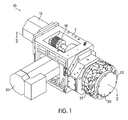
FIG. 1 shows an example of an indexing tool turret assembly in accordance with one embodiment of the invention; -
FIG. 2 shows a cross-section of the indexing tool turret assembly ofFIG. 1 taken along line 2-2, in accordance with an embodiment of the invention; -
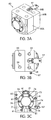
FIG. 3 shows various views of a housing for supporting a driven pulley as shown inFIG. 2 , where:-
FIG. 3A shows an isometric view of the housing; -
FIG. 3B shows a front elevation view of the housing; -
FIG. 3C shows a top plan view of the housing; -
FIG. 3D shows a left side elevation view of the housing, with the right side (not shown) essentially being a mirror image thereof; -
FIG. 3E shows a bottom plan view of the housing; -
FIG. 3F shows a back elevation view of the housing; -
FIG. 4 shows an enlarged sectional view the housing ofFIG. 3 with the live tool coupling in a disengaged position; -
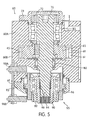
FIG. 5 shows an enlarged sectional view the housing ofFIG. 3 with the live tool coupling in an engaged position; and -
FIG. 6 shows a spindle motor mounting plate with a coolant loop formed therein, in accordance with one embodiment of the invention.
-
- As can be seen in
FIG. 1 , an indexing tool turret assembly according to the present invention is generally indicated at 10. Theindexing tool turret 10 includes aturret housing 5 that supports atop plate assembly 20. Theturret housing 5 may be configured to conventionally mount to a machine, such as a CNC machining center. - The
top plate assembly 20 includes a plurality oftoolholders 25 spaced radially around thetop plate assembly 20. Eachtoolholder 25 is configured to support and drive a desired tool T, e.g., a rotary cutting or machining tool, such as an endmill. Thetop plate assembly 20 is rotatable about a central axis (coincident with line 2-2) of thetop plate assembly 20 with respect to theturret frame 5 by an indexingmotor 15. In that regard, thetop plate assembly 20 may be selectively indexed, such that one of themultiple toolholders 25 is located in an operative position, with theother toolholders 25 located in an indexing position. Thetoolholder 25 in the operative position may also be referred to as the live toolholder 25'. Aspindle motor 30 is used to provide the rotational force to drive the live toolholder 25' and the desired tool T. - In one embodiment, both the
index motor 15 andspindle motor 30 may be for example, variable speed, reversible electric motors, but other types of drive units, including hydraulic and pneumatic units may also be used. -
FIG. 2 shows a cross-section ofFIG. 1 taken along line 2-2. Thetop plate assembly 20 is mounted to and supported by ahub 50. In one embodiment, thehub 50 is rotationally mounted to anindex bearing support 52 with bearings orbushings 53. Theindex bearing support 52 is mounted to theturret housing 5 by fasteners e.g., screws (not shown). This configuration allows thetop plate assembly 20 to be rotationally indexed with respect to theturret housing 5. A drive gear (not shown) operatively connected to the indexingmotor 15 via a coupling 18 (visible inFIG. 1 ), engages with a drivengear 55 attached to thehub 50 so as to rotate thetop plate assembly 20 with respect to theturret housing 5. - The
turret housing 5 may further be constructed with arecessed portion 32 so as to accommodate thespindle motor 30. Thespindle motor 30 may be mounted on and supported by amotor mounting plate 75, which is attached to the bottom of the recessedportion 32 of theturret housing 5, for example, using fasteners. Adrive pulley 40 is attached to theoutput shaft 35 of the spindle motor 30and is aligned with the center of theindex bearing support 52. An opening 51 in theindex bearing support 52 allows abelt 45 to pass through it. In that regard, thebelt 45 rotationally connects thedrive pulley 40 of thespindle motor 30 to a drivenpulley 65, which may be coupled to the live toolhoolder 25'. Thebelt 45 may be formed of rubber, polymer, or other elastomer material that may be sufficiently tensioned to effectively allow thespindle motor 30 to drive the drivenpulley 65. - The
drive pulley 40 may be connected to theoutput shaft 35 of thespindle motor 30 by atorque limiting coupling 43. Thetorque limiting coupling 43 protects thebelt 45 from being damaged and/or broken due to excessive torque being provided by thespindle motor 30. In an overload condition, i.e., when a maximum predetermined torque is reached, thetorque limiter 43 will rotationally disengage thedrive pulley 40 from theoutput shaft 35 of thespindle motor 30, so that thebelt 45 is protected from the overload. For details regarding thetorque limiting coupling 43, see for exampleU.S. Patent No. 3,722,644 , herein incorporated by reference. - Inside the
top plate assembly 20, ahousing 60 surrounds the drivenpulley 65 supported on atool driving shaft 70. Acover plate 21 of thetop plate assembly 20 that is attached withfasteners 22 permits access therein. Thehousing 60 is mounted to theindex bearing support 52 while thetop plate assembly 20 is mounted tohub 50 for relative rotation between thehousing 60 andtop plate assembly 20. - The
housing 60 is may be constructed as a sub-assembly, as shown inFIG. 3 . While two portions, upper andlower pieces housing 60 are shown, any number of portions are contemplated. Access to the drivenpulley 65 and also thebelt 45 connected thereto, may be achieved be removing at least one portion of the housing, which may be referred to as a removable portion of the housing. The other portion of the housing may be referred to as a main portion of the housing. -
FIG. 3A shows an isometric view ofhousing 60.FIG. 3B shows a front elevation view of thehousing 60. Thehousing 60 may be fastened to theindex bearing support 52 by fasteners (not shown), for example four M8 bolts, to be installed in thruholes 59. The twopieces housing 60 may be connected usingfasteners 61, for example, six M6 screws. In one embodiment, the twopieces housing 60 may be aligned using two tapered dowel pins 62 prior to insertion of thefasteners 61.FIG. 3C shows a top plan view of thehousing 60. Anupper bearing retainer 73 is connected to theupper piece 60A of thehousing 60 byfasteners 74. -
FIG. 3D shows a left side elevation view of thehousing 60, with the right side (not shown) essentially being a mirror image thereof.FIG. 3E shows a bottom plan view ofhousing 60. Alower retainer 93 is connected to thelower piece 60B of thehousing 60 byfasteners 91. -
FIG. 3F shows a back elevation view of thehousing 60.Apertures 62 provide access tohousing 60 for thebelt 45 to pass through. -
FIGS. 4 and5 show an enlarged sectional view of thehousing 60. Upper andlower pieces housing 60 each include acomplementary recess portion 61, which provide a space to accommodate the drivenpulley 65, when thehousing 60 is assembled. Thetool driving shaft 70 is supported by upper andlower bearing assemblies lower pieces housing 60. In one embodiment, thelower bearing assembly 80 may be a needle bearing. However, it will be appreciated that other types of bearings and/or bushings may be used for thelower bearing assembly 80. - The
housing 60 provides better structural support to the drivenpulley 65 andtool driving shaft 70, because thehousing 60 supports thetool driving shaft 70 above and below the tensionedbelt 45. Thetool driving shaft 70 may be supported by theupper bearing assembly 85 and thelower bearing assembly 80 on opposite sides of the drivenpulley 65. This configuration balances the forces of the drivenpulley 65 and may reduce vibrations. At the same time, thehousing 60 facilitates replacement of worn orbroken belts 45. - The
upper piece 60A of thehousing 60 includes theupper bearing assembly 85 for rotationally supporting the upper end of thetool driving shaft 70. Thetop lock nut 72 is used to apply a preload theupper bearing assembly 85. Finally, theupper bearing assembly 85 is retained within theupper piece 60A of thehousing 60 by theupper bearing retainer 73. Theupper bearing retainer 73 further prevents dirt/dust from entering theupper bearing assembly 85. - The
lower piece 60B of thehousing 60 includes apiston assembly 95 for engaging and disengaging the live toolholder 25' with thetool driving shaft 70. Agrease fitting 87 is provided on thelower piece 60B of thehousing 60 for providing lubrication to thelower bearing assembly 80. -
Fluid coupling ports FIG. 3F , are provided for connecting thepiston assembly 95 to an external fluid pressure source (not shown), for example, a hydraulic or pneumatic source, for driving thepiston assembly 95. Thepiston assembly 95 includes apiston bearing assembly 96 for rotationally supporting the piston, alive tool coupling 90 for engaging the live toolholder 25', alock nut 92 for applying a preload to thepiston bearing assembly 96, and thelower retainer 93 for retaining thepiston assembly 95 within thelower piece 60B of thehousing 60. - The
live tool coupling 90 includes an external splined or keyedconnection 94 to rotationally couple live tool coupling 90 with thetool driving shaft 70, while allowing thelive tool coupling 90 to axially displace with respect to thetool driving shaft 70. Further, thelive tool coupling 90 may be provided with an internal splined or keyedconnection 99 at its lower distal end to rotationally couple the live tool coupling 90 with the live toolholder 25'. When thepiston assembly 95 is engaged, as shown inFIG. 5 , thelive tool coupling 90 is in an extended position to engage the live toolholder 25', making the live toolholder 25' rotationally coupled to thespindle motor 30 via the internal splined or keyedconnection 99. In this position, thelive toolholder 25 may be used to perform a machining operation with the desire tool T, such as milling or boring. Conversely, when thepiston assembly 95 is disengaged, as shown inFIG. 4 , thelive tool coupling 90 is in a disengaged position, so as to disengage the live toolholder 25'. In this position, the live toolholder 25' is no longer coupled to thespindle motor 30 and thetop plate assembly 20 may be freely rotated. This allows for indexing of the anothertoolholder 25 to the operative position using theindexing motor 15. - A
bracket 97 attached to thelower piece 60B of thehousing 60 extends from the bottom of thehousing 60 and includes first andsecond proximity sensors first proximity sensor 98A is positioned and configured to detected whether thepiston assembly 95 is in a retracted position, for example, as shown inFIG. 4 . Similarly, thesecond proximity sensor 98B is positioned and configured to detected whether thepiston assembly 95 is in a extended position, for example, as shown inFIG. 5 . In one embodiment, the first andsecond proximity sensors - The
spindle motor 30 is mounted on the spindlemotor mounting plate 75, which may be provided with a coolant channel orloop 76 to dissipate heat from thespindle motor 30 and thereby discourage thermal expansion and/or contraction of the indexingtool turret assembly 10. - In one embodiment, the
coolant loop 76 may be formed directly within themotor mounting plate 75 to reduce space, as shown inFIG. 6 . Anopening 79 in themotor mounting plate 75 provides an opening of sufficient size to allow thedrive pulley 40 attached to theoutput shaft 35 of thespindle motor 30 to extend through it. Oblongmotor mounting holes 77 allow thespindle motor 30 to be mounted with fasteners (not shown) to themotor mounting plate 75. The oblongmotor mounting holes 77 permit thespindle motor 30 and thedrive pulley 40 to be laterally shifted while the fasteners are loosely tightened, in order to apply tension to (or alternatively relieve tension of)belt 45. Further, mountingholes 78 are provided to mount themotor mounting plate 75 to the bottom of therecess 32 of theturret housing 5. - The
motor mounting plate 75 may be formed of a material that conducts heat, such as a metal, in particular, aluminum or aluminum alloy. In one embodiment, thecoolant loop 76 may be formed during the machining of themotor mounting plate 75. Plugs (not shown) may be then inserted intomachining bores coolant loop 76 may be cast or otherwise formed within themotor mounting plate 75, as will be appreciated by those skilled in the art. A coolant or heat transfer fluid, for example water or a glycol, may be flowed through thecoolant loop 76 to an external heat exchanger (not shown) to remove latent heat from the mountingplace 75 andspindle motor 30. In alternative embodiments, thespindle motor 30 may be cooled using a jacket, sleeve, or coil, placed around the body of thespindle motor 30. - To replace a worn or
broken belt 45, tension on thebelt 45 is first relied by loosening, but not necessarily removing, the fasteners for mounting thespindle motor 30 to themotor mounting plate 75. This permits the fasteners to slide laterally in the oblongmotor mounting holes 77, thereby permitting thespindle motor 30 and drivingpulley 40 to slide laterally within theopening 79 to relieve tension on thebelt 45. - Next the
cover 21 of thetop plate assembly 20 may be removed by removingfasters 22 to expose thehousing 60. Thehousing 60 is then separated from theindex bearing support 52, for example, by removing fasteners from thruholes 59. Next, theupper piece 60A of thehousing 60 may be removed from thehousing 60 by removingfasteners 61 and tapered pins 62. With theupper piece 60A of thehousing 60 removed, the drivenpulley 65 andbelt 45 are fully accessible. Areplacement belt 45 may be installed or other maintenance performed. - The
housing 60 may be reassembled and mounted to theindex bearing support 52 in a reverse procedure. Finally, thebelt 45 is tensioned and the fasteners for mounting thespindle motor 30 to themotor mounting plate 75 are fully tightened. - In the disclosed embodiment, the transmission shaft of the conventional tool turret assembly is not required. The
housing 60 of the disclosed embodiment supports thetool driving shaft 70 from above and below the tensionedbelt 45. Thetool driving shaft 70 may be supported byupper bearing assembly 85 andlower bearing assembly 80 on opposite sides of the drivenpulley 65. This configuration balances the forces of the drivenpulley 65 and may reduce vibrations. At the same time, the construction ofhousing 60 may facilitate replacement of worn orbroken belts 45. - While this invention has been described in connection with what is presently considered to be the most practical and preferred embodiment, it is to be understood that it is capable of further modifications and is not to be limited to the disclosed embodiment, and this application is intended to cover any variations, uses, equivalent arrangements or adaptations of the invention following, in general, the principles of the invention and including such departures from the present disclosure as come within known or customary practice in the art to which the invention pertains, and as may be applied to the essential features hereinbefore set forth and followed in the scope of the appended claims.
Claims (14)
- An indexing tool turret assembly (10), comprising:a turret housing (5);a top plate assembly (20) that supports a plurality of toolholders (25), the toolholders (25) each constructed and arranged to hold a respective machining tool (T), the top plate assembly (20) being rotatable with respect to the turret housing (5), such that one of the plurality of toolholders (25) can be positioned in an operative position;a motor (30);a driven pulley (65) that is driven by the motor (30);a tool driving shaft (70) arranged to drive the toolholder (25) that is in the operative position, the tool driving shaft (70) being driven by the driven pulley (65);a belt (45) connecting the motor (30) to the driven pulley (65); anda housing (60) for the driven pulley (65), the housing (60) having a main portion (60A, 60B) that supports the tool driving shaft (70) on one side of the driven pulley (65), and a removable portion (60A, 60B),wherein the assembly is characterized by:the removable portion (60A, 60B) supporting the tool driving shaft (70) on an opposite side of the driven pulley (65) from the main portion (60A, 60B), andthe removable portion (60A, 60B) being removable to permit access to the driven pulley (65).
- An indexing tool turret assembly (10) according to claim 1, comprising a live tool coupling (90) axially displaceable with respect to the tool driving shaft (70) allowing the tool driving shaft (70) to be rotationally coupled to the toolholder (25) that is in the operative position.
- An indexing tool turret assembly (10) according to claim 2, wherein an engagement between the live tool coupling (90) and the tool driving shaft (70) is a splined or keyed connection (94).
- An indexing tool turret assembly (10) according to claim 2 or claim 3, comprising a piston assembly (95) configured to engage and disengage the live tool coupling (90) with the toolholder (25) in the operative position.
- An indexing tool turret assembly (10) according to any of claims 2 to 4, comprising at least one sensor (98A, 98B) for determining whether the live tool coupling (90) is engaged or disengaged to the toolholder (25) in the operative position.
- An indexing tool turret assembly (10) according to any of claims 1 to 5, wherein an output shaft of the motor (30) comprises a drive pulley (40) that is aligned with the driven pulley (65).
- An indexing tool turret assembly (10) according to claim 6, wherein a torque limiting coupling (43) is provided between the output shaft of the motor (30) and the drive pulley (40), so as to limit the maximum torque that may be provided to the belt (45).
- An indexing tool turret assembly (10) according to any of claims 1 to 7, wherein the main portion (60A, 60B) carries a bearing assembly (80, 85) that supports the tool driving shaft (70) on one side of the driven pulley (65), and the removable portion (60A, 60B) carries a bearing assembly (80, 85) that supports the tool driving shaft (70) on an opposite side of the driven pulley (65).
- An indexing tool turret assembly (10) according to any of claims 1 to 8, wherein the plurality of toolholders (25) are radially spaced around the top plate assembly (20).
- An indexing tool turret assembly (10) according to any of claims 1 to 9, comprising an indexing motor (15) configured to index the top plate assembly (20) to locate one of the plurality of toolholders (25) in the operative position.
- An indexing tool turret assembly (10) according to any of claims 1 to 10, comprising a mounting plate (75) that mounts the motor (30) to the turret housing (5), a coolant loop (76) being formed in mounting plate (75) to dissipate heat from the motor (30).
- An indexing tool turret assembly (10) according to any of claims 1 to 11, wherein the top plate assembly (20) is rotatably supported on a hub (50) connected to the turret housing (5).
- An indexing tool turret assembly according to any of claims 1 to 12, wherein with the removable portion (60A, 60B) removed, the driven pulley (65) and the belt (45) are fully accessible.
- An indexing tool turret assembly according to any of claims 1 to 13, wherein removal of the removable portion (60A, 60B) creates an access opening in the main portion (60A, 60B), and wherein the driven pulley (65) protrudes out of the access opening when the removable portion (60A, 60B) is removed.
Applications Claiming Priority (2)
| Application Number | Priority Date | Filing Date | Title |
|---|---|---|---|
| US11/772,968 US7647679B2 (en) | 2007-07-03 | 2007-07-03 | Belt-driven indexing tool turret assembly |
| PCT/US2008/068718 WO2009006372A1 (en) | 2007-07-03 | 2008-06-30 | Belt-driven indexing tool turret assembly |
Publications (2)
| Publication Number | Publication Date |
|---|---|
| EP2173519A1 EP2173519A1 (en) | 2010-04-14 |
| EP2173519B1 true EP2173519B1 (en) | 2011-06-22 |
Family
ID=39789589
Family Applications (1)
| Application Number | Title | Priority Date | Filing Date |
|---|---|---|---|
| EP08781154A Not-in-force EP2173519B1 (en) | 2007-07-03 | 2008-06-30 | Belt-driven indexing tool turret assembly |
Country Status (7)
| Country | Link |
|---|---|
| US (1) | US7647679B2 (en) |
| EP (1) | EP2173519B1 (en) |
| JP (1) | JP5281083B2 (en) |
| KR (1) | KR101531655B1 (en) |
| CN (1) | CN101795816B (en) |
| AT (1) | ATE513652T1 (en) |
| WO (1) | WO2009006372A1 (en) |
Families Citing this family (15)
| Publication number | Priority date | Publication date | Assignee | Title |
|---|---|---|---|---|
| DE102010037927B4 (en) * | 2009-10-02 | 2014-04-10 | Hardinge Inc. | toolholder |
| KR101157323B1 (en) | 2009-12-18 | 2012-06-15 | 한화테크엠주식회사 | Belt type tool turret |
| CN101870074B (en) * | 2010-06-01 | 2011-12-28 | 郑金凤 | Precision turning angle shifting and automatic clamping mechanism |
| AR091569A1 (en) | 2012-06-28 | 2015-02-11 | Intervet Int Bv | TOLL TYPE RECEIVERS |
| DE102012025399A1 (en) * | 2012-12-24 | 2014-06-26 | Sauter Feinmechanik Gmbh | Alignment device, alignment element for such an alignment device and alignment method |
| US10156290B2 (en) * | 2015-02-06 | 2018-12-18 | FLIR Belgium BVBA | Belt drive tensioning system |
| KR101675566B1 (en) * | 2015-02-17 | 2016-11-11 | 이더블유에스 코리아 주식회사 | Tool turret having a confirm for disk status |
| KR101640740B1 (en) * | 2015-10-19 | 2016-07-19 | 주식회사 스맥 | Belt turret apparatus |
| WO2017122288A1 (en) * | 2016-01-13 | 2017-07-20 | 富士機械製造株式会社 | Coolant apparatus for machine tool |
| CN106670521B (en) * | 2017-02-21 | 2018-11-06 | 台州开启精密机械有限公司 | Servo turret and damper piston cylinder |
| CN110125728B (en) * | 2019-04-16 | 2021-10-15 | 上海航天化工应用研究所 | Multi-station processing system |
| CN110355391B (en) * | 2019-07-06 | 2021-07-06 | 广东圣特斯数控设备有限公司 | Servo tool changing device |
| GB2605456A (en) * | 2021-04-01 | 2022-10-05 | Crafti Tech Ltd | Apparatus |
| CN115179057A (en) * | 2022-08-25 | 2022-10-14 | 南京大地水刀股份有限公司 | Balanced type Z is to structure |
| US20240149382A1 (en) | 2022-11-09 | 2024-05-09 | Hardinge, Inc. | Method for forming a workpiece and machine for implementing said method |
Family Cites Families (20)
| Publication number | Priority date | Publication date | Assignee | Title |
|---|---|---|---|---|
| US3722644A (en) | 1972-01-31 | 1973-03-27 | Twin Disc Inc | Torque limiting coupling |
| DE3202042C2 (en) * | 1982-01-23 | 1987-01-22 | G. Boley GmbH & Co, Werkzeugmaschinenfabrik, 7300 Esslingen | Tool turrets for machine tools, especially lathes |
| JPS62102906A (en) | 1985-10-30 | 1987-05-13 | Kira Tekkosho:Kk | Tool spindle drive device in turret boring machine |
| US4949443A (en) * | 1988-06-29 | 1990-08-21 | Tatsuhiko Saruwatari | Numerically controlled lathe |
| JPH0398791A (en) | 1989-09-12 | 1991-04-24 | Japan Tobacco Inc | Dividing/cutting device for fruit and vegetable |
| JPH0596403A (en) | 1991-10-04 | 1993-04-20 | Tsugami Corp | Machine tool tool equipment |
| DE4235095C2 (en) * | 1992-10-17 | 1997-04-30 | Gildemeister Ag | Tool turret |
| FR2704789B1 (en) * | 1993-05-07 | 1995-06-30 | Schleicher Didier | MULTI-SPINDLE REVOLVER HEAD FOR MACHINE TOOL. |
| IT1268332B1 (en) | 1994-09-16 | 1997-02-27 | Sasib Spa | HANDLING DEVICE FOR HANDLING, IN PARTICULAR FOR THE ORIENTATION OF PIECES, TOOLS OR SIMILAR. |
| JP3044456B2 (en) | 1995-11-27 | 2000-05-22 | 本田技研工業株式会社 | Turret type machine tool |
| JPH09220624A (en) | 1996-02-15 | 1997-08-26 | Amada Co Ltd | High speed rotary turret of punch press |
| JPH10315014A (en) | 1997-05-13 | 1998-12-02 | Hitachi Seiki Co Ltd | Lathe turret |
| JPH11347814A (en) * | 1998-06-05 | 1999-12-21 | Okuma Corp | Tool rest |
| US6785943B2 (en) | 1998-09-04 | 2004-09-07 | Hardinge, Inc. | Indexing tool turret |
| CN2356803Y (en) * | 1998-10-23 | 2000-01-05 | 台湾凸轮股份有限公司 | Tool change synchronous device |
| US6119330A (en) | 1999-04-21 | 2000-09-19 | Cheng; Chin Chung | Fully automatic cutting metal-working machine |
| CN2413845Y (en) * | 2000-01-12 | 2001-01-10 | 台湾凸轮股份有限公司 | Automatic Clamping Device for Tool Replacement of Comprehensive Processing Machine |
| JP4251630B2 (en) | 2003-12-17 | 2009-04-08 | 株式会社森精機製作所 | Machine tool turret |
| JP4379877B2 (en) | 2004-09-29 | 2009-12-09 | 株式会社森精機製作所 | Machine tool turret |
| KR100655919B1 (en) | 2006-01-17 | 2006-12-11 | 이더블유에스 코리아 주식회사 | Belt type turret tool stand |
-
2007
- 2007-07-03 US US11/772,968 patent/US7647679B2/en not_active Expired - Fee Related
-
2008
- 2008-06-30 JP JP2010515213A patent/JP5281083B2/en not_active Expired - Fee Related
- 2008-06-30 CN CN2008801051569A patent/CN101795816B/en not_active Expired - Fee Related
- 2008-06-30 WO PCT/US2008/068718 patent/WO2009006372A1/en not_active Ceased
- 2008-06-30 AT AT08781154T patent/ATE513652T1/en not_active IP Right Cessation
- 2008-06-30 KR KR1020107002407A patent/KR101531655B1/en active Active
- 2008-06-30 EP EP08781154A patent/EP2173519B1/en not_active Not-in-force
Also Published As
| Publication number | Publication date |
|---|---|
| JP2010532279A (en) | 2010-10-07 |
| EP2173519A1 (en) | 2010-04-14 |
| KR20100050497A (en) | 2010-05-13 |
| CN101795816B (en) | 2012-06-13 |
| US20090007406A1 (en) | 2009-01-08 |
| WO2009006372A1 (en) | 2009-01-08 |
| US7647679B2 (en) | 2010-01-19 |
| ATE513652T1 (en) | 2011-07-15 |
| JP5281083B2 (en) | 2013-09-04 |
| CN101795816A (en) | 2010-08-04 |
| KR101531655B1 (en) | 2015-06-25 |
Similar Documents
| Publication | Publication Date | Title |
|---|---|---|
| US7647679B2 (en) | Belt-driven indexing tool turret assembly | |
| US7326010B2 (en) | Motor spindle | |
| US11059139B2 (en) | Drilling-milling device having a device for evening out the torque and the rotational speed of the spindle | |
| EP0799106B1 (en) | Front-loading rotary ring cutter | |
| US8132991B2 (en) | Protection device for a motor spindle | |
| US20050271488A1 (en) | Machine tool for working ring-shaped workpieces | |
| US20040256908A1 (en) | Hydraulic milling machine for excavators | |
| JP4139971B2 (en) | Spindle device | |
| JP2007245255A (en) | Machine tool headstock | |
| KR101664107B1 (en) | Excellent processing equipment for the assembling of RAM | |
| KR20090020238A (en) | One motor axle type turret tool stand | |
| KR102625092B1 (en) | Tool apparatus of machine tools | |
| US6880429B1 (en) | Transmission assembly | |
| KR102222775B1 (en) | Indexing clamp module for turret device | |
| CA2884058C (en) | Drive arrangement for direct drive rotor | |
| EP2047947A1 (en) | Tool-holding gearbox for machine tools | |
| KR20160101359A (en) | Tool turret having a confirm for disk status | |
| EP4703072A1 (en) | Tool turret with axial motor | |
| CN211438663U (en) | Chuck seat assembly | |
| KR101633068B1 (en) | tool turret with gear box | |
| CN219310094U (en) | Gear type spindle mechanism | |
| JP2008055576A (en) | Rotary tool turret | |
| CN121821121A (en) | A tool head drive device for a swashplate tool magazine | |
| JPH0121687Y2 (en) | ||
| KR20170135533A (en) | Gear box having a cooling flow path |
Legal Events
| Date | Code | Title | Description |
|---|---|---|---|
| PUAI | Public reference made under article 153(3) epc to a published international application that has entered the european phase |
Free format text: ORIGINAL CODE: 0009012 |
|
| 17P | Request for examination filed |
Effective date: 20100126 |
|
| AK | Designated contracting states |
Kind code of ref document: A1 Designated state(s): AT BE BG CH CY CZ DE DK EE ES FI FR GB GR HR HU IE IS IT LI LT LU LV MC MT NL NO PL PT RO SE SI SK TR |
|
| AX | Request for extension of the european patent |
Extension state: AL BA MK RS |
|
| 17Q | First examination report despatched |
Effective date: 20100413 |
|
| DAX | Request for extension of the european patent (deleted) | ||
| GRAP | Despatch of communication of intention to grant a patent |
Free format text: ORIGINAL CODE: EPIDOSNIGR1 |
|
| GRAS | Grant fee paid |
Free format text: ORIGINAL CODE: EPIDOSNIGR3 |
|
| GRAA | (expected) grant |
Free format text: ORIGINAL CODE: 0009210 |
|
| AK | Designated contracting states |
Kind code of ref document: B1 Designated state(s): AT BE BG CH CY CZ DE DK EE ES FI FR GB GR HR HU IE IS IT LI LT LU LV MC MT NL NO PL PT RO SE SI SK TR |
|
| REG | Reference to a national code |
Ref country code: GB Ref legal event code: FG4D |
|
| REG | Reference to a national code |
Ref country code: CH Ref legal event code: EP |
|
| REG | Reference to a national code |
Ref country code: IE Ref legal event code: FG4D |
|
| REG | Reference to a national code |
Ref country code: DE Ref legal event code: R096 Ref document number: 602008007817 Country of ref document: DE Effective date: 20110811 |
|
| REG | Reference to a national code |
Ref country code: NL Ref legal event code: VDEP Effective date: 20110622 |
|
| PG25 | Lapsed in a contracting state [announced via postgrant information from national office to epo] |
Ref country code: NO Free format text: LAPSE BECAUSE OF FAILURE TO SUBMIT A TRANSLATION OF THE DESCRIPTION OR TO PAY THE FEE WITHIN THE PRESCRIBED TIME-LIMIT Effective date: 20110922 Ref country code: SE Free format text: LAPSE BECAUSE OF FAILURE TO SUBMIT A TRANSLATION OF THE DESCRIPTION OR TO PAY THE FEE WITHIN THE PRESCRIBED TIME-LIMIT Effective date: 20110622 Ref country code: HR Free format text: LAPSE BECAUSE OF FAILURE TO SUBMIT A TRANSLATION OF THE DESCRIPTION OR TO PAY THE FEE WITHIN THE PRESCRIBED TIME-LIMIT Effective date: 20110622 Ref country code: LT Free format text: LAPSE BECAUSE OF FAILURE TO SUBMIT A TRANSLATION OF THE DESCRIPTION OR TO PAY THE FEE WITHIN THE PRESCRIBED TIME-LIMIT Effective date: 20110622 |
|
| PG25 | Lapsed in a contracting state [announced via postgrant information from national office to epo] |
Ref country code: AT Free format text: LAPSE BECAUSE OF FAILURE TO SUBMIT A TRANSLATION OF THE DESCRIPTION OR TO PAY THE FEE WITHIN THE PRESCRIBED TIME-LIMIT Effective date: 20110622 Ref country code: FI Free format text: LAPSE BECAUSE OF FAILURE TO SUBMIT A TRANSLATION OF THE DESCRIPTION OR TO PAY THE FEE WITHIN THE PRESCRIBED TIME-LIMIT Effective date: 20110622 Ref country code: SI Free format text: LAPSE BECAUSE OF FAILURE TO SUBMIT A TRANSLATION OF THE DESCRIPTION OR TO PAY THE FEE WITHIN THE PRESCRIBED TIME-LIMIT Effective date: 20110622 Ref country code: CY Free format text: LAPSE BECAUSE OF FAILURE TO SUBMIT A TRANSLATION OF THE DESCRIPTION OR TO PAY THE FEE WITHIN THE PRESCRIBED TIME-LIMIT Effective date: 20110622 Ref country code: GR Free format text: LAPSE BECAUSE OF FAILURE TO SUBMIT A TRANSLATION OF THE DESCRIPTION OR TO PAY THE FEE WITHIN THE PRESCRIBED TIME-LIMIT Effective date: 20110923 Ref country code: LV Free format text: LAPSE BECAUSE OF FAILURE TO SUBMIT A TRANSLATION OF THE DESCRIPTION OR TO PAY THE FEE WITHIN THE PRESCRIBED TIME-LIMIT Effective date: 20110622 |
|
| PG25 | Lapsed in a contracting state [announced via postgrant information from national office to epo] |
Ref country code: BE Free format text: LAPSE BECAUSE OF FAILURE TO SUBMIT A TRANSLATION OF THE DESCRIPTION OR TO PAY THE FEE WITHIN THE PRESCRIBED TIME-LIMIT Effective date: 20110622 Ref country code: NL Free format text: LAPSE BECAUSE OF FAILURE TO SUBMIT A TRANSLATION OF THE DESCRIPTION OR TO PAY THE FEE WITHIN THE PRESCRIBED TIME-LIMIT Effective date: 20110622 Ref country code: MT Free format text: LAPSE BECAUSE OF FAILURE TO SUBMIT A TRANSLATION OF THE DESCRIPTION OR TO PAY THE FEE WITHIN THE PRESCRIBED TIME-LIMIT Effective date: 20110622 |
|
| PG25 | Lapsed in a contracting state [announced via postgrant information from national office to epo] |
Ref country code: EE Free format text: LAPSE BECAUSE OF FAILURE TO SUBMIT A TRANSLATION OF THE DESCRIPTION OR TO PAY THE FEE WITHIN THE PRESCRIBED TIME-LIMIT Effective date: 20110622 Ref country code: PT Free format text: LAPSE BECAUSE OF FAILURE TO SUBMIT A TRANSLATION OF THE DESCRIPTION OR TO PAY THE FEE WITHIN THE PRESCRIBED TIME-LIMIT Effective date: 20111024 Ref country code: IS Free format text: LAPSE BECAUSE OF FAILURE TO SUBMIT A TRANSLATION OF THE DESCRIPTION OR TO PAY THE FEE WITHIN THE PRESCRIBED TIME-LIMIT Effective date: 20111022 |
|
| PG25 | Lapsed in a contracting state [announced via postgrant information from national office to epo] |
Ref country code: RO Free format text: LAPSE BECAUSE OF FAILURE TO SUBMIT A TRANSLATION OF THE DESCRIPTION OR TO PAY THE FEE WITHIN THE PRESCRIBED TIME-LIMIT Effective date: 20110622 Ref country code: SK Free format text: LAPSE BECAUSE OF FAILURE TO SUBMIT A TRANSLATION OF THE DESCRIPTION OR TO PAY THE FEE WITHIN THE PRESCRIBED TIME-LIMIT Effective date: 20110622 Ref country code: PL Free format text: LAPSE BECAUSE OF FAILURE TO SUBMIT A TRANSLATION OF THE DESCRIPTION OR TO PAY THE FEE WITHIN THE PRESCRIBED TIME-LIMIT Effective date: 20110622 |
|
| REG | Reference to a national code |
Ref country code: IE Ref legal event code: MM4A |
|
| PLBE | No opposition filed within time limit |
Free format text: ORIGINAL CODE: 0009261 |
|
| STAA | Information on the status of an ep patent application or granted ep patent |
Free format text: STATUS: NO OPPOSITION FILED WITHIN TIME LIMIT |
|
| PG25 | Lapsed in a contracting state [announced via postgrant information from national office to epo] |
Ref country code: IE Free format text: LAPSE BECAUSE OF NON-PAYMENT OF DUE FEES Effective date: 20110630 |
|
| REG | Reference to a national code |
Ref country code: FR Ref legal event code: ST Effective date: 20120406 |
|
| 26N | No opposition filed |
Effective date: 20120323 |
|
| PG25 | Lapsed in a contracting state [announced via postgrant information from national office to epo] |
Ref country code: DK Free format text: LAPSE BECAUSE OF FAILURE TO SUBMIT A TRANSLATION OF THE DESCRIPTION OR TO PAY THE FEE WITHIN THE PRESCRIBED TIME-LIMIT Effective date: 20110622 |
|
| REG | Reference to a national code |
Ref country code: DE Ref legal event code: R097 Ref document number: 602008007817 Country of ref document: DE Effective date: 20120323 |
|
| PG25 | Lapsed in a contracting state [announced via postgrant information from national office to epo] |
Ref country code: FR Free format text: LAPSE BECAUSE OF NON-PAYMENT OF DUE FEES Effective date: 20110822 |
|
| REG | Reference to a national code |
Ref country code: CH Ref legal event code: PL |
|
| REG | Reference to a national code |
Ref country code: CH Ref legal event code: PL |
|
| GBPC | Gb: european patent ceased through non-payment of renewal fee |
Effective date: 20120630 |
|
| PG25 | Lapsed in a contracting state [announced via postgrant information from national office to epo] |
Ref country code: MC Free format text: LAPSE BECAUSE OF NON-PAYMENT OF DUE FEES Effective date: 20110630 Ref country code: ES Free format text: LAPSE BECAUSE OF FAILURE TO SUBMIT A TRANSLATION OF THE DESCRIPTION OR TO PAY THE FEE WITHIN THE PRESCRIBED TIME-LIMIT Effective date: 20111003 Ref country code: GB Free format text: LAPSE BECAUSE OF NON-PAYMENT OF DUE FEES Effective date: 20120630 Ref country code: LI Free format text: LAPSE BECAUSE OF NON-PAYMENT OF DUE FEES Effective date: 20120630 Ref country code: CH Free format text: LAPSE BECAUSE OF NON-PAYMENT OF DUE FEES Effective date: 20120630 |
|
| PG25 | Lapsed in a contracting state [announced via postgrant information from national office to epo] |
Ref country code: LU Free format text: LAPSE BECAUSE OF NON-PAYMENT OF DUE FEES Effective date: 20110630 |
|
| PG25 | Lapsed in a contracting state [announced via postgrant information from national office to epo] |
Ref country code: BG Free format text: LAPSE BECAUSE OF FAILURE TO SUBMIT A TRANSLATION OF THE DESCRIPTION OR TO PAY THE FEE WITHIN THE PRESCRIBED TIME-LIMIT Effective date: 20110922 |
|
| PGFP | Annual fee paid to national office [announced via postgrant information from national office to epo] |
Ref country code: CZ Payment date: 20130612 Year of fee payment: 6 Ref country code: DE Payment date: 20130626 Year of fee payment: 6 |
|
| PGFP | Annual fee paid to national office [announced via postgrant information from national office to epo] |
Ref country code: IT Payment date: 20130619 Year of fee payment: 6 |
|
| PG25 | Lapsed in a contracting state [announced via postgrant information from national office to epo] |
Ref country code: TR Free format text: LAPSE BECAUSE OF FAILURE TO SUBMIT A TRANSLATION OF THE DESCRIPTION OR TO PAY THE FEE WITHIN THE PRESCRIBED TIME-LIMIT Effective date: 20110622 |
|
| PG25 | Lapsed in a contracting state [announced via postgrant information from national office to epo] |
Ref country code: HU Free format text: LAPSE BECAUSE OF FAILURE TO SUBMIT A TRANSLATION OF THE DESCRIPTION OR TO PAY THE FEE WITHIN THE PRESCRIBED TIME-LIMIT Effective date: 20110622 |
|
| REG | Reference to a national code |
Ref country code: DE Ref legal event code: R119 Ref document number: 602008007817 Country of ref document: DE |
|
| PG25 | Lapsed in a contracting state [announced via postgrant information from national office to epo] |
Ref country code: CZ Free format text: LAPSE BECAUSE OF NON-PAYMENT OF DUE FEES Effective date: 20140630 |
|
| REG | Reference to a national code |
Ref country code: DE Ref legal event code: R119 Ref document number: 602008007817 Country of ref document: DE Effective date: 20150101 |
|
| PG25 | Lapsed in a contracting state [announced via postgrant information from national office to epo] |
Ref country code: DE Free format text: LAPSE BECAUSE OF NON-PAYMENT OF DUE FEES Effective date: 20150101 Ref country code: IT Free format text: LAPSE BECAUSE OF NON-PAYMENT OF DUE FEES Effective date: 20140630 |