EP2173214B1 - Hair care device with function head - Google Patents
Hair care device with function head Download PDFInfo
- Publication number
- EP2173214B1 EP2173214B1 EP08785084.8A EP08785084A EP2173214B1 EP 2173214 B1 EP2173214 B1 EP 2173214B1 EP 08785084 A EP08785084 A EP 08785084A EP 2173214 B1 EP2173214 B1 EP 2173214B1
- Authority
- EP
- European Patent Office
- Prior art keywords
- ion
- hair
- outlet
- hair care
- functional head
- Prior art date
- Legal status (The legal status is an assumption and is not a legal conclusion. Google has not performed a legal analysis and makes no representation as to the accuracy of the status listed.)
- Active
Links
- 210000004209 hair Anatomy 0.000 title claims abstract description 112
- 150000002500 ions Chemical class 0.000 claims abstract description 176
- 239000002184 metal Substances 0.000 claims description 13
- 238000004146 energy storage Methods 0.000 claims 1
- 230000001154 acute effect Effects 0.000 description 3
- 238000007599 discharging Methods 0.000 description 3
- 230000000694 effects Effects 0.000 description 3
- 238000010438 heat treatment Methods 0.000 description 3
- 239000012811 non-conductive material Substances 0.000 description 3
- 230000002411 adverse Effects 0.000 description 2
- 238000010276 construction Methods 0.000 description 2
- 230000005686 electrostatic field Effects 0.000 description 2
- 239000000463 material Substances 0.000 description 2
- 230000007704 transition Effects 0.000 description 2
- 238000009827 uniform distribution Methods 0.000 description 2
- 238000004026 adhesive bonding Methods 0.000 description 1
- 230000015572 biosynthetic process Effects 0.000 description 1
- 230000001680 brushing effect Effects 0.000 description 1
- 239000000919 ceramic Substances 0.000 description 1
- 239000011248 coating agent Substances 0.000 description 1
- 238000000576 coating method Methods 0.000 description 1
- 230000001419 dependent effect Effects 0.000 description 1
- 238000009826 distribution Methods 0.000 description 1
- 230000008030 elimination Effects 0.000 description 1
- 238000003379 elimination reaction Methods 0.000 description 1
- 230000005669 field effect Effects 0.000 description 1
- 238000007493 shaping process Methods 0.000 description 1
- 230000003068 static effect Effects 0.000 description 1
- 210000002105 tongue Anatomy 0.000 description 1
Images


Classifications
-
- A—HUMAN NECESSITIES
- A45—HAND OR TRAVELLING ARTICLES
- A45D—HAIRDRESSING OR SHAVING EQUIPMENT; EQUIPMENT FOR COSMETICS OR COSMETIC TREATMENTS, e.g. FOR MANICURING OR PEDICURING
- A45D20/00—Hair drying devices; Accessories therefor
- A45D20/04—Hot-air producers
- A45D20/08—Hot-air producers heated electrically
- A45D20/10—Hand-held drying devices, e.g. air douches
- A45D20/12—Details thereof or accessories therefor, e.g. nozzles, stands
-
- A—HUMAN NECESSITIES
- A45—HAND OR TRAVELLING ARTICLES
- A45D—HAIRDRESSING OR SHAVING EQUIPMENT; EQUIPMENT FOR COSMETICS OR COSMETIC TREATMENTS, e.g. FOR MANICURING OR PEDICURING
- A45D20/00—Hair drying devices; Accessories therefor
- A45D20/48—Hair-drying combs or hair-drying brushes, with internal heating means
- A45D20/50—Hair-drying combs or hair-drying brushes, with internal heating means and provision for an air stream
-
- A—HUMAN NECESSITIES
- A45—HAND OR TRAVELLING ARTICLES
- A45D—HAIRDRESSING OR SHAVING EQUIPMENT; EQUIPMENT FOR COSMETICS OR COSMETIC TREATMENTS, e.g. FOR MANICURING OR PEDICURING
- A45D20/00—Hair drying devices; Accessories therefor
- A45D20/52—Hair-drying combs or hair-drying brushes, adapted for heating by an external heating source, e.g. air stream
- A45D20/525—Hair-drying combs or hair-drying brushes, adapted for heating by an external heating source, e.g. air stream by an independent heating source
-
- A—HUMAN NECESSITIES
- A46—BRUSHWARE
- A46B—BRUSHES
- A46B15/00—Other brushes; Brushes with additional arrangements
- A46B15/0002—Arrangements for enhancing monitoring or controlling the brushing process
-
- A—HUMAN NECESSITIES
- A46—BRUSHWARE
- A46B—BRUSHES
- A46B15/00—Other brushes; Brushes with additional arrangements
- A46B15/0002—Arrangements for enhancing monitoring or controlling the brushing process
- A46B15/0016—Arrangements for enhancing monitoring or controlling the brushing process with enhancing means
- A46B15/0024—Arrangements for enhancing monitoring or controlling the brushing process with enhancing means with means generating ions
-
- A—HUMAN NECESSITIES
- A45—HAND OR TRAVELLING ARTICLES
- A45D—HAIRDRESSING OR SHAVING EQUIPMENT; EQUIPMENT FOR COSMETICS OR COSMETIC TREATMENTS, e.g. FOR MANICURING OR PEDICURING
- A45D1/00—Curling-tongs, i.e. tongs for use when hot; Curling-irons, i.e. irons for use when hot; Accessories therefor
- A45D1/02—Curling-tongs, i.e. tongs for use when hot; Curling-irons, i.e. irons for use when hot; Accessories therefor with means for internal heating, e.g. by liquid fuel
- A45D1/04—Curling-tongs, i.e. tongs for use when hot; Curling-irons, i.e. irons for use when hot; Accessories therefor with means for internal heating, e.g. by liquid fuel by electricity
-
- A—HUMAN NECESSITIES
- A45—HAND OR TRAVELLING ARTICLES
- A45D—HAIRDRESSING OR SHAVING EQUIPMENT; EQUIPMENT FOR COSMETICS OR COSMETIC TREATMENTS, e.g. FOR MANICURING OR PEDICURING
- A45D20/00—Hair drying devices; Accessories therefor
- A45D20/04—Hot-air producers
- A45D20/08—Hot-air producers heated electrically
- A45D20/10—Hand-held drying devices, e.g. air douches
-
- A—HUMAN NECESSITIES
- A45—HAND OR TRAVELLING ARTICLES
- A45D—HAIRDRESSING OR SHAVING EQUIPMENT; EQUIPMENT FOR COSMETICS OR COSMETIC TREATMENTS, e.g. FOR MANICURING OR PEDICURING
- A45D2200/00—Details not otherwise provided for in A45D
- A45D2200/20—Additional enhancing means
- A45D2200/202—Ionisation
-
- A—HUMAN NECESSITIES
- A46—BRUSHWARE
- A46B—BRUSHES
- A46B2200/00—Brushes characterized by their functions, uses or applications
- A46B2200/10—For human or animal care
- A46B2200/104—Hair brush
Definitions
- the present invention relates to a hair care appliance having a handle, a functional head connectable to the handle, which has a hair processing device, in particular a bristle and / or tine field, and an ion applicator for applying ions to the hair, which has at least one ion outlet.
- hair care appliances especially hairbrushes
- hairbrushes which in addition to their primary function, i.
- ions bring out.
- Such ions are usually molecules charged with negative electrons.
- the hair and hair care can be improved, in particular, a static charging of the hair and a corresponding projection of the hair can be avoided.
- a hair brush or a hair dryer with integrated brush attachment which has on an away from the bristle field back of the device and on a bristle field carrying device front side each having an ion outlet, the ions leak in the direction of the function head.
- the ions are on the one hand, of course, deliberately applied to the hair, on the other hand, no punctiform, but as evenly distributed as possible impingement of the hair done.
- the ion discharge is hindered not only by direct mechanical obstacles, such as hairs located in front of the ion outlet, or a user's hand in the way, but also by electrostatic opposing fields, which are strongly negatively charged components, which, so to speak, fend off the negatively charged ions Components with high positive charges, which have an attractive field effect on the ions can go out. Charges of this type can, for example, be generated on the bristle field itself when it is combed through the hair. Also in the region of the ion outlet, electrostatic fields can form on the device housing, which can hinder the ion emission.
- the present invention has the object to provide an improved hair care device of the type mentioned, which avoids the disadvantages of the prior art and further develops the latter in an advantageous manner.
- a uniform, efficient ion discharge to the hair should be achieved with simple means, but without affecting the safety of use of the device.
- the hair care device is characterized in that the functional head and / or a housing part in the vicinity of the ion outlet at least a first ground surface for removal / limitation of electronic charges and said device back side, preferably on a component inside, is provided with at least a second ground plane , This second grounding surface may or may not be in the vicinity of the ionic outlet.
- a third grounding surface is arranged at the function head.
- the grounding surface that is to say in each case both the first grounding surface and the second and further grounding surfaces, can be designed as desired. It may have a flat or punctiform contact area, via which a removal / limitation of electronic charges takes place. It may further comprise a contact plate which is connected to another surface, for example an inner surface or outer surface of a plastic component, for example by gluing. The contact surface can be made rigid or flexible. Further, the ground surface may comprise an electrically contacted screw which is screwed into a screw dome in the plastic part.
- a grounding surface should be considered herein to be disposed "in the vicinity" of another, if it can act on the other component, that is, capable of dissipating / limiting electronic charges from that other component.
- the component can be contacted directly from the grounding surface or even indirectly. Even with indirect Contacting the distance to the component should not be more than 1 or 5 or 10 millimeters. The distance may depend on the electrical conductivity of the component or components to be bridged.
- the functional head and / or a housing part in the vicinity of the ion outlet can have at least one further grounding surface for discharging / limiting electrostatic charges ("third grounding surface").
- a grounding surface on the functional head and / or on a housing part surrounding the ionic outlet prevents or limits excessive charging and accordingly electrostatic fields in the region of the functional head and in the region of the ionic outlet, which could hinder the ion discharge onto the hair.
- ground surfaces may be present both on the functional head and on the housing part in the vicinity of the ion outlet.
- the grounding surface can basically be designed differently.
- the grounding surface may be formed in the form of a metal surface, which is applied to a non-conductive, preferably made of plastic body or housing part of the functional head and / or the Ionenauslasses.
- the body of the functional part or of the ionic outlet per se can therefore continue to be formed as a plastic injection-molded part or a plastic part manufactured in another way.
- the ground surface in the form of a metal surface which can advantageously be arranged on an outer side of said body parts and form their outer surface, thereby not only prevents the ion discharge impairing fields, but also increases the reliability of the hair care device.
- a grounding surface can also be provided on an inner surface of a body part.
- the arrangement on the inside or outside can be different depending on the component.
- the grounding surface on the said functional head and / or on an outlet housing enclosing the ion outlet may be provided on an outer surface of the corresponding body part, it brings about particular advantages on a further body part in the vicinity of the ion outlet, in particular in an exit direction the outlet body part over which the ion cloud propagates to provide a grounding surface or device on the inner surface of the corresponding body part.
- an advantageous arrangement may be that the grounding surface is connected to the hair treatment device, in particular the bristle and / or tine field.
- the grounding surface may form, as it were, the bed which carries the bristles or prongs of the bristle field or the possibly also differently designed processing tool of the hair processing device.
- the hair processing device may, for example, also have a care surface made of a suitable material, such as ceramic, for hair care.
- a heating surface with a suitable shape, in particular a smooth, concave and / or convexly rounded working surface be provided.
- the ion outlet comprises a preferably separate housing module, which encloses a high-voltage element emitting the box box and / or box-shaped and has an orifice side, in which an outlet opening for discharging the ions generated by the high voltage element is provided.
- the aforesaid ground plane is provided on one of the non-muzzle sides of said housing package.
- the mouth side of the housing module can in particular be designed entirely free of counterelectrodes.
- the grounding surface can be arranged on a side face of the outlet housing which adjoins the mouth side and which surrounds the aforementioned, preferably spike, pin or tip-shaped high-voltage element on the circumference.
- a grounding surface may also be provided on a rear outlet housing surface, which is opposite to the mouth side.
- a ground surface at the ion outlet may form a housing surface surrounding a high voltage element for emitting ions.
- a housing component adjacent to the ion outlet and / or a housing surface arranged in the vicinity of the ion outlet may also be provided with a ground ("second grounding surface").
- a housing member may be grounded downstream of the ionic port over which the ion cloud is intended to propagate, which housing component may advantageously be made of a non-conductive material and provided with a grounding surface applied thereto.
- the electric Grounding of the housing component in the vicinity of the ion outlet can be carried out in the simplest embodiment via an electrically contacted screw in a Screw dome is screwed into the plastic part.
- the electrical grounding can take place via a contact pressure of a metal electrode, which forms a grounding surface of the aforementioned type.
- Said housing component or said housing components can be earthed via a contact to the ground potential of the voltage circuit of the device, whereby an electrostatic charge is not impossible, but is sufficiently limited to keep the electric opposing fields resulting from the charging so small that they do not hinder the propagation of the ions from the ionic outlet.
- the electrical grounding of the housing component, over which the ion cloud propagates advantageously takes place not in the field of view of the ion cloud, but rather on a housing component side facing away from the ion outlet, in particular an inner surface of the housing component.
- the device housing can be provided in an area over which the ion cloud emerging from the ion outlet, and / or in the vicinity of the ion outlet with a lonenleit- or ion control device.
- a control of the ions can hereby be achieved in an advantageous manner by providing a plurality of separate housing components in the vicinity of the ion outlet, of which at least one is grounded and at least one further earth is formed. While the ungrounded housing part can charge electrically and thereby deflect the ions, the ions can propagate unhindered over the grounded housing components, so that by a corresponding pattern of grounded and ungrounded housing components, the propagation of the exiting ions can be controlled accordingly.
- such an ion guide can be designed differently to produce different propagation patterns.
- a preferred embodiment of the invention may be provided in the vicinity of the Ionenauslasses a symmetrical to the device longitudinal plane symmetrical pattern of grounded and ungrounded housing components, so that a total symmetrical ion propagation is achieved.
- a deviating from the symmetry with respect to the longitudinal center plane configuration can be made, for example, to create a targeted device for right-handed or a device for left-handers.
- the grounding surface on the functional head can also surround the hair treatment device at least in sections, preferably in a ring shape and / or directly adjacent to the hair treatment device.
- a metal strip may be provided around the hair treatment device on the functional head as a grounding surface.
- the hair processing device itself so for example, the bristle and / or tine field, or the housing body of the functional head itself consist of non-conductive material.
- the grounding surface on the functional head is not provided in the immediate vicinity of the at least one ionic outlet.
- the grounding surface may advantageously be arranged on the edge next to the hair processing device in the functional head carrying the hair processing device.
- the housing potential is also electrically contacted with the body of the user.
- the handle of the hair care appliance can have an electrically conductive contact surface for discharging positive charges to the respective user of the hair care appliance. This protects the user from charging. Namely, the release of negative ions can negatively charge the applicator. On the other hand, positive contact charges can be transmitted to the user through the contact surface on the handle, whereby the charging effect is compensated by the negative ions. This is particularly advantageous in the case of an embodiment of the hair care appliance without a mains connection, in particular as a battery and / or cordless appliance.
- the generation of negative ions usually causes an equivalent amount of positive charge on the device, since the device as a battery or cordless device, the reference potential is missing. Due to this positive charge on the device, a negative charging of the user can be compensated for via the aforementioned electrically effective contact surface on the handle.
- the arrangement of the ion outlet or all the ion outlets on the rear side of the device causes the ion to exit without mechanical hindrances by means of a user's hand or strands of hair located in front of the ion outlet.
- a single ion outlet may be sufficient.
- several ion outlets can be arranged on the back of the device.
- the arrangement is advantageously made symmetrical to the longitudinal center plane of the hair care device.
- the at least one ion outlet or the plurality of ion outlets is preferably such that a main exit direction of the ions or the sum of the main exit directions of the ions is directed in the plane of the rear side surface or over the surface of the rear side symmetrically to the longitudinal center plane.
- the main exit direction of the ion outlet is advantageously substantially - aligned roughly parallel to the rear side surface, so that the ions emerge substantially parallel to the rear side of the device.
- a slightly acute angle (upwards) splayed ion delivery may be provided.
- the ion outlet at an angle of preferably 0 ° to 45 °, preferably 0 ° to 30 °, be inclined to the surface of the back.
- the at least one ion outlet is arranged at the edge of the device rear surface, which is opposite the hair processing device, so that an ion cloud forms over the rear side of the functional head.
- ion outlet is arranged in the longitudinal center plane itself.
- two ion outlets on the back of the device they can be spaced apart from the longitudinal center plane at the same height to each other and preferably inclined slightly inclined to the median plane.
- an opposing arrangement can be provided such that both ion outlets are arranged on opposite edges of the rear functional microscope surface and directed towards each other, so that they allow the ions to exit one another as it were.
- the hair processing device can be firmly connected to the functional head and can also be firmly integrated into the functional head.
- the hair treatment device can advantageously be exchangeably mounted on the functional head, so that a functional head can be connected and used with different hair processing device.
- a bristle or tine field also other hair processing device in question, such as: a heat treatment device, a heatable hair straightener, a hot air device, such as a hair dryer or a hot air brush.
- a heat treatment device such as: a heat treatment device, a heatable hair straightener, a hot air device, such as a hair dryer or a hot air brush.
- Such various hair processing devices typically require various ways of handing and gripping the device, so it is advantageous to offer electrically conductive surfaces in the manner disclosed.
- the ion current should be delivered so that it is well compatible in both its strength, as well as its geometric distribution with a variety of functional heads.
- hair care device 1 comprises a device body 2, which has a handle 3 and in its interior or on its outer shell to be described yet electronic devices.
- Said handle 3 carries a functional head 4, which carries a bristle field 6 as a hair processing device 5 on the front of the device 7.
- hair processing tools such as heating elements or hair styling elements or possibly also a fan output, may be provided when the hair care device is designed as a hair styling device and / or hair dryer.
- the mentioned hair processing tools can also be combined if necessary.
- the said hair processing device 5 can be firmly integrated into the functional head 4.
- the hair processing device 5 can advantageously be exchangeable be mounted to the functional head 4, so that a functional head 4 with different hair processing devices 5 can be equipped and used.
- the hair-care appliance 1 can have a modular construction with a plurality of components that can be connected, wherein, in particular, the entire functional head 4 and / or the hair-processing apparatus 5 can be formed separately from the appliance body 2 in the aforementioned manner.
- advantageously positively acting connection means may be provided, for example in the form of locking tongues and pockets that allow a tool-free removal and replacement of the blocks.
- an ion discharge device 9 is provided on the device base body 2 on its rear side 8 facing away from the hair processing device 5, which comprises an ion emitter which is arranged in the interior of the device base body 2 and / or can have a high-voltage element 12 arranged in the ion outlet 11 for emitting the ions.
- Said high-voltage element 12 can be arranged in a box-like or jacket-like outlet housing 13, the wall of which has on an outlet side 14 an outlet opening 17 through which the emitted ions can escape.
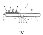
- the ion outlet 11 is formed nozzle-shaped or diffuser-like and causes a directed ion leakage, cf. FIG. 2 .
- the ion outlet 11 is arranged on the rear side of the device 8, which is opposite to the bristle field 6 or facing away from it and, so to speak, forms the back of the hairbrush.
- the ion outlet 11 is arranged in the longitudinal center plane 18, which the drawing plane of FIG. 2 forms, wherein advantageously the ion outlet 11 with its main exit direction 19 slightly inclined at an acute angle to the rear side of the device surface and directed away from this, see.
- FIG. 1 the ion outlet 11 with its main exit direction 19 slightly inclined at an acute angle to the rear side of the device surface and directed away from this, see.
- the angle of inclination is advantageously between 0 ° and 45 ° and in the illustrated embodiment may advantageously be approximately between 20 ° and 30 °.
- the ion outlet 11 is arranged at the edge of the rear side surface of the functional head, which is opposite to the bristle field 6, so that the ions emerging from the ion outlet 11 form an ion cloud over the rear side of the functional head 4.
- the ion outlet 11 can, as FIG. 1 shows, roughly - be arranged in the transition region between the handle 3 and the functional head 4.
- a not specifically shown power supply unit is housed, which may preferably be in the form of a battery or rechargeable battery device.
- the hair care device 1 is designed to be energy self-sufficient, i. it does not have a permanent power supply that would provide power from the outlet.
- a power cord can be plugged in to charge the batteries inside the device body 2.
- the ion discharge device 9 is fed to effect the ion generation.
- the hair care device 1 is advantageously provided with a grounding device 20 in order to avoid unwanted device charging, to avoid interference with the ion leakage and to improve the safety of the device operation.
- the grounding device 20 may have a grounding surface 21 ("third grounding surface") which prevents the construction of high charge fields in the region of the functional head 4, in particular in the region of the hair processing device 5.
- the grounding surface 21 is directly connected to the hair processing device 5, being formed as a carrier and seated under the hair processing device 5 mounted thereon, cf.
- FIG. 1 shows that the hair care device 1 is advantageously provided with a grounding device 20 in order to avoid unwanted device charging, to avoid interference with the ion leakage and to improve the safety of the device operation.
- the grounding device 20 may have a grounding surface 21 ("third grounding surface") which prevents the construction of high charge fields in the region of the functional head 4, in particular in the region of the hair processing device 5.
- the grounding surface 21 is directly connected to the hair processing device 5, being formed as a carrier
- the grounding surface 21 advantageously consists of a metal surface and / or a metal coating, which is applied to the otherwise made of plastic functional head body.
- the grounding surface 21 may be connected to the ground potential of the voltage circuit, for example by means disposed in the interior of the device ground blocks.
- the functional head-side grounding surface 21 may also have a metal surface body arranged on the edge of the bristle field 6, preferably in the form of a metal strip, which annularly surrounds the bristle field 6, or, as in FIG FIG. 3 represented, U-shaped encloses from three sides.
- the bristle field 6 and the remaining body of the functional head 4 may be non-conductive, in particular made of plastic.
- the grounding surface 21 surrounds a sufficient part of the bristle field 6 in order to limit charges arising there to a sufficient extent.
- the metal strip will extend along at least 50% of the circumference of the hair processing device 5.
- the hair care device 1 on its rear side 8 also have a plurality of ion outlets 11, wherein in the illustrated embodiment according to the FIGS. 4 and 5 two ion outlets 11 are provided which, viewed in the longitudinal direction of the device, are arranged at the same height and are positioned symmetrically relative to one another with respect to the longitudinal center plane 18.
- the ion outlets 11 are arranged at the edge of the functional head back, wherein they are inclined at an angle of the order of 60 ° to 120 °, preferably about 90 ° to each other to produce a uniformly distributed ion cloud.
- the ion outlets 11 are aligned with their main exit direction 18 parallel to the surface of the rear of the device 8, so that the ions emerge substantially parallel to the back of the functional head. In the illustrated embodiment, the ion outlets 11 allow the ions to emerge in diverging directions in order to distribute an ion cloud uniformly over the functional head 4 or its rear side.
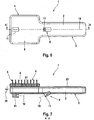
- FIGS. 4 and 5 can also be arranged a plurality of ion outlets 11 in the longitudinal center plane 18, cf.
- FIGS. 6 and 7 Advantageously, the two ion outlets 11 are directed opposite to one another, wherein they are arranged on opposite sides in edge regions of the functional head rear side, cf. FIGS. 6 and 7 to let out an ion cloud over the back of the function head.
- the two ion outlets 11 may be differently inclined to the surface of the rear of the device. While an ionic outlet is aligned with its main exit direction 18 substantially parallel to the surface of the rear of the device 8, the other ionic outlet 11 is inclined at an acute angle to the surface of the device rear side, preferably at an angle of 0 ° to 40 °, in particular 10 ° to 30 ° , As the FIGS. 6 and 7 show, it may be particularly advantageous if the arranged in the transition region between the handle 3 and the function head 4 ion outlet 11 is slightly inclined, while arranged on the remote from the handle 3 end of the back of the functional head ion outlet 11 can be arranged parallel to the rear of the device 8.
- the aforementioned grounding device 20 advantageously also includes a grounding surface 22 ("first grounding surface") assigned to the ionic outlet 11.
- this grounding surface 22 is provided on a housing outer surface of the outlet housing 13, which surrounds the ion emitter or its high-voltage element 12.
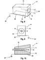
- FIG. 8 best shows, includes - roughly speaking box-shaped outlet housing 13 an end side forming a muzzle side 14, in the an outlet opening 17 is provided for the exit of the emitted ions.
- the high-voltage element 12 is arranged centrally in the outlet housing 13 and ends shortly before said outlet opening 17 in the interior of the outlet housing 13, cf.
- the high-voltage element 12 typically comprises or consists of a wire, while the outlet housing is made, for example, of plastic (the schematic FIG. 10 does not make material differences apparent).
- FIGS. 8 to 10 is a - with respect to the high voltage element 12 circumferentially - side surface 16 is provided with the ground surface 22.
- This can be done according to the FIGS. 8 to 10 a bottom side of the outlet housing 13, which faces the device base body 2. Alternatively or additionally, this may also be a side wall surface 16 of the outlet housing 13, as this FIG. 12 shows.
- the entire bottom side of the outlet housing 13 is formed as a grounding surface 22, in particular in the form of a metal surface, wherein the housing body, moreover, can not be made conductive and in particular made of plastic.
- the corresponding area - in the case of FIG. 11 the bottom-side side surface of the outlet housing 13 may also be provided only partially with the grounding surface 22, ie the grounding surface 22 does not necessarily cover the entire side surface, cf. FIG. 11 ,
- the rear side of the outlet housing 13, which is opposite to the mouth side 14, may be formed as a grounding surface 22.
- FIG. 14 Another version shows FIG. 14 , Here, opposing side surfaces 16 of the outlet housing 13 are each provided with a ground surface 22, which are formed in the illustrated embodiment only in the form of a side surfaces 16 partially covering strip.
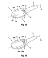
- a hair care appliance 1 shows Fig. 15 , Unless otherwise described, this hair care device can correspond to the previous embodiments, wherein corresponding components corresponding reference numerals in Fig. 15 are used. Essentially, the hair care device differs according to Fig. 15 from the previous ones by the fact that the entire rear side of the functional head is earthed.
- the housing component 108 which forms the back of the functional head 4 and surrounds the ionic outlet 11, consists in itself of non-conductive material, in particular of plastic, so that the housing component 108 can be electrostatically charged per se.
- said housing member 108 is grounded through contact with the ground potential of the high voltage circuit, whereby the electrostatic charge is not impossible, but sufficiently limited, so that the charging electric counter fields are so small that they do not propagate the ions from the ion outlet hinder.
- the electrical grounding can take place via the grounding surface 122 ("second grounding surface").
- the grounding surface 122 may in this case also be designed as an electrically contacted screw in a screw dome in the housing component 108.
- a pressure of a metal electrode may be applied to the housing member 108 preferably on the inside thereof. In both cases, therefore, a connected to the ground potential grounding surface is provided on the housing member 108 in order to prevent or suppress the electrostatic charge.
- the grounded housing member 108 extends in the vicinity of the Ionenauslasses 11 substantially over the entire rear body surface of the device or its portion over which propagates the ion emerging from the ion outlet 11 ion cloud.
- the grounded housing component 108 extends starting from a rear side of the ion outlet 11 facing away from the outlet side 14 of the ion outlet 11, in particular over a large area up to the ion outlet 11, ie downstream of the ion outlet 11 viewed in the exit direction of the ions from said ion outlet 11, cf.
- the ionic outlet 11 forms, so to speak, an island in the surface of the grounded housing component 108, wherein the larger part of the housing component 108, in the illustrated embodiment more than two-thirds of the housing component 108, lies on the outlet side of the ionic outlet 11, cf. Fig. 15 ,
- Said ionic outlet 11 is integrated in said housing member 108, in particular, the latter bulges dome-shaped to make room for the outlet opening 17 of the Ionenauslasses 11, which is formed in the illustrated embodiment of a sleeve 170, preferably made of plastic, the ion emitter enclosing the outlet side, cf. Fig. 15 ,
- a plurality of separate housing components 108 a and 108 b may be provided, of which at least one is grounded, while at least one other is not grounded.
- the ungrounded parts can become electrostatically charged, which deflects the ions.
- the ions can propagate undisturbed over the grounded parts, so that overall control of the ion cloud is achieved.
- the pattern of grounded and ungrounded housing components in the vicinity of the ion outlet 11 thus forms a lonenleitvorrichung.
- Fig. 16 shows this ion guide or the pattern of grounded and ungrounded housing components 108 a and 108 b may be advantageously arranged symmetrically to the longitudinal center plane 18 of the hair care device 1 or formed.
- Fig. 16 a central, from the ion outlet 11 away trapezoidal widening housing member 108 a, which is grounded in the aforementioned manner.
- This central, strip-shaped housing component 108 a is flanked on the right and left by two lateral housing components 108 b, which remain ungrounded and thus can charge electrostatically.
- the ion guide so to speak, forms an exit channel or corridor, which permits a targeted ion exit and suppresses excessive lateral spreading.
- other patterns of grounded or ungrounded housing components can be provided in order to achieve appropriate control of the propagation of the ion cloud, depending on the application.
Landscapes
- Brushes (AREA)
- Electrotherapy Devices (AREA)
- Cosmetics (AREA)
Abstract
Description
Die vorliegende Erfindung betrifft ein Haarpflegegerät mit einem Griff, einem mit dem Griff verbindbaren Funktionskopf, der eine Haarbearbeitungsvorrichtung, insbesondere ein Borsten- und/oder Zinkenfeld, aufweist, sowie einer Ionenausbringvorrichtung zum Ausbringen von Ionen auf das Haar, die zumindest einen Ionenauslass aufweist.The present invention relates to a hair care appliance having a handle, a functional head connectable to the handle, which has a hair processing device, in particular a bristle and / or tine field, and an ion applicator for applying ions to the hair, which has at least one ion outlet.
In jüngerer Zeit sind Haarpflegegeräte, insbesondere Haarbürsten, bekannt geworden, die neben ihrer primären Funktion, d.h. im Falle einer Haarbürste Kämmen, Bürsten und Formen des Haares, als Zusatzapplikation Ionen ausbringen. Derartige Ionen sind üblicherweise mit negativen Elektronen beladene Moleküle. Mit Hilfe einer solchen Ionenapplikation kann das Haar und die Haarpflege verbessert werden, insbesondere kann ein statisches Aufladen der Haare und ein entsprechendes Abstehen der Haare vermieden werden.Recently, hair care appliances, especially hairbrushes, have come to be known, which in addition to their primary function, i. In the case of a hairbrush combing, brushing and shaping the hair, as an additional application ions bring out. Such ions are usually molecules charged with negative electrons. With the help of such ion application, the hair and hair care can be improved, in particular, a static charging of the hair and a corresponding projection of the hair can be avoided.
Aus der
Bei derartigen Haarpflegegeräten mit Ionenapplikation sollen die Ionen einerseits natürlich gezielt auf das Haar ausgebracht werden, andererseits soll keine punktuelle, sondern eine möglichst gleichmäßig verteilte Beaufschlagung des Haars erfolgen. Der Ionenaustrag wird dabei nicht nur durch unmittelbare mechanische Hindernisse, wie vor dem Ionenauslass befindliche Haare oder eine im Weg liegende Hand des Benutzers, behindert, sondern auch durch elektrostatische Gegenfelder, die von stark negativ geladenen Bauteilen, die die negativ geladenen Ionen sozusagen abwehren, oder Bauteilen mit hohen positiven Ladungen, die eine anziehende Feldwirkung auf die Ionen haben, ausgehen können. Derartige Ladungen können beispielsweise an dem Borstenfeld selbst entstehen, wenn mit diesem durch die Haare gekämmt wird. Auch im Bereich des Ionenauslasses können sich elektrostatische Felder am Gerätegehäuse bilden, die den Ionenaustritt behindern können.In such hair care devices with ion application, the ions are on the one hand, of course, deliberately applied to the hair, on the other hand, no punctiform, but as evenly distributed as possible impingement of the hair done. In this case, the ion discharge is hindered not only by direct mechanical obstacles, such as hairs located in front of the ion outlet, or a user's hand in the way, but also by electrostatic opposing fields, which are strongly negatively charged components, which, so to speak, fend off the negatively charged ions Components with high positive charges, which have an attractive field effect on the ions can go out. Charges of this type can, for example, be generated on the bristle field itself when it is combed through the hair. Also in the region of the ion outlet, electrostatic fields can form on the device housing, which can hinder the ion emission.
Ein weiterer zu verbessernder Aspekt bei vorbekannten Haarpflegegeräten der genannten Art ist die Benutzungssicherheit, die durch die vorgenannten starken Aufladungen am Gerät beeinträchtigt werden kann.Another aspect to be improved in previously known hair care devices of the type mentioned is the safety of use, which can be adversely affected by the aforementioned heavy charges on the device.
Hiervon ausgehend liegt der vorliegenden Erfindung die Aufgabe zugrunde, ein verbessertes Haarpflegegerät der genannten Art zu schaffen, das Nachteile des Standes der Technik vermeidet und letzteren in vorteilhafter Weise weiterbildet. Insbesondere soll mit einfachen Mitteln ein gleichmäßiger, effizienter Ionenaustrag auf das Haar erreicht werden, ohne aber die Benutzungssicherheit des Geräts zu beeinträchtigen.Proceeding from this, the present invention has the object to provide an improved hair care device of the type mentioned, which avoids the disadvantages of the prior art and further develops the latter in an advantageous manner. In particular, a uniform, efficient ion discharge to the hair should be achieved with simple means, but without affecting the safety of use of the device.
Erfindungsgemäß wird diese Aufgabe durch ein Haarpflegegerät gemäß Anspruch 1 gelöst. Bevorzugte Ausgestaltungen der Erfindung sind Gegenstand der abhängigen Ansprüche.According to the invention this object is achieved by a hair care device according to
Es wird also vorgeschlagen, eine elektrostatische Aufladung und Gegenfelder zumindest an den Teilen des Haarpflegegeräts durch geeignete Gegenmaßnahmen zu beseitigen, die dem Ionenaustrag auf das Haar im Weg stehen bzw. den Ionenaustrag beeinträchtigen können. Ohne Beeinträchtigung durch solche elektrostatischen Gegenfelder kann eine gleichmäßig verteilte, nichtsdestotrotz jedoch gezielte und effiziente lonenbeaufschlagung des Haars auch mit einer nur einfachen Ausbildung der Ionenausbringvorrichtung erreicht werden, die in einer einfachen Ausbildung der Erfindung mit nur einem einzigen Ionenauslass auskommen kann. Erfindungsgemäß zeichnet sich das Haarpflegegerät dadurch aus, dass der Funktionskopf und/oder ein Gehäuseteil in der Umgebung des Ionenauslasses zumindest eine erste Erdungsfläche zur Abfuhr/Begrenzung von elektronischen Ladungen aufweist und die genannte Geräterückseite, vorzugsweise auf einer Bauteilinnenseite, mit zumindest einer zweiten Erdungsfläche versehen ist. Diese zweite Erdungsfläche kann sich auch in der Umgebung des Ionenauslasses befinden, muss dies aber nicht. Am Funktionskopf ist eine dritte Erdungsfläche angeordnet.It is therefore proposed to eliminate an electrostatic charge and opposing fields at least on the parts of the hair care device by means of suitable countermeasures which stand in the way of the ion discharge on the hair or can impair the ion discharge. Without being adversely affected by such electrostatic opposing fields, uniformly distributed but nevertheless targeted and efficient ionization of the hair can be achieved with only simple formation of the ion applicator device, which in a simple embodiment of the invention can manage with only a single ionic outlet. According to the invention, the hair care device is characterized in that the functional head and / or a housing part in the vicinity of the ion outlet at least a first ground surface for removal / limitation of electronic charges and said device back side, preferably on a component inside, is provided with at least a second ground plane , This second grounding surface may or may not be in the vicinity of the ionic outlet. At the function head, a third grounding surface is arranged.
Die Erdungsfläche, das heißt jeweils sowohl die erste Erdungsfläche, als auch die zweite und weitere Erdungsflächen, kann dabei beliebig gestaltet sein. Sie kann einen flächigen oder punktförmigen Kontaktbereich aufweisen, über den eine Abfuhr/Begrenzung von elektronischen Ladungen erfolgt. Sie kann ferner eine Kontaktplatte aufweisen, die mit einer anderen Fläche, beispielsweiser einer Innenfläche oder Aussenfläche eines Kunststoffbauteils verbunden ist, beispielsweise durch Klebung. Die Kontaktfläche kann starr oder biegsam ausgeführt sein. Ferner kann die Erdungsfläche eine elektrisch kontaktierte Schraube umfassen, die in einen Schraubdom im Plastikteil eingeschraubt ist.The grounding surface, that is to say in each case both the first grounding surface and the second and further grounding surfaces, can be designed as desired. It may have a flat or punctiform contact area, via which a removal / limitation of electronic charges takes place. It may further comprise a contact plate which is connected to another surface, for example an inner surface or outer surface of a plastic component, for example by gluing. The contact surface can be made rigid or flexible. Further, the ground surface may comprise an electrically contacted screw which is screwed into a screw dome in the plastic part.
Eine Erdungsfläche soll hierin dann als "in der Umgebung" eines anderen angeordnet gelten, wenn sie auf das andere Bauteil wirken kann, das heißt zur Abfuhr/Begrenzung von elektronischen Ladungen von diesem anderen Bauteil geeigent ist. Das Bauteil kann dazu direkt von der Erdungsfläche kontaktiert werden oder auch nur indirekt. Auch bei indirekter Kontaktierung sollte der Abstand zum Bauteil nicht mehr als 1 oder 5 oder 10 Millimeter betragen. Der Abstand kann von der elektrischen Leitfähigkeit des Bauteils oder zu überbrückender Bauteile abhängen.A grounding surface should be considered herein to be disposed "in the vicinity" of another, if it can act on the other component, that is, capable of dissipating / limiting electronic charges from that other component. The component can be contacted directly from the grounding surface or even indirectly. Even with indirect Contacting the distance to the component should not be more than 1 or 5 or 10 millimeters. The distance may depend on the electrical conductivity of the component or components to be bridged.
Ferner kann der Funktionskopf und/oder ein Gehäuseteil in der Umgebung des Ionenauslasses zumindest eine weitere Erdungsfläche zur Abfuhr/Begrenzung von elektrostatischen Ladungen aufweisen ("dritte Erdungsfläche"). Eine derartige Erdungsfläche am Funktionskopf und/oder an einem den Ionenauslass umgebenden Gehäuseteil verhindert bzw. begrenzt eine übermäßige Aufladung und dementsprechend elektrostatische Felder im Bereich des Funktionskopfs und im Bereich des Ionenauslasses, die den Ionenaustrag auf das Haar behindern könnten. Insbesondere können dabei sowohl am Funktionskopf als auch an dem Gehäuseteil in der Umgebung des Ionenauslasses derartige Erdungsflächen vorhanden sein.Furthermore, the functional head and / or a housing part in the vicinity of the ion outlet can have at least one further grounding surface for discharging / limiting electrostatic charges ("third grounding surface"). Such a grounding surface on the functional head and / or on a housing part surrounding the ionic outlet prevents or limits excessive charging and accordingly electrostatic fields in the region of the functional head and in the region of the ionic outlet, which could hinder the ion discharge onto the hair. In particular, such ground surfaces may be present both on the functional head and on the housing part in the vicinity of the ion outlet.
Die Erdungsfläche kann dabei grundsätzlich verschieden ausgebildet sein. Insbesondere kann die Erdungsfläche in Form einer Metalloberfläche ausgebildet sein, die auf einem nicht leitenden, vorzugsweise aus Kunststoff bestehenden Korpus- bzw. Gehäuseteil des Funktionskopfes und/oder des Ionenauslasses aufgebracht ist. Der Korpus des Funktionsteils bzw. des Ionenauslasses an sich kann also weiterhin als Kunststoffspritzgussteil oder in anderer Weise gefertigtes Kunststoffteil ausgebildet sein. Die Erdungsfläche in Form einer Metalloberfläche, die vorteilhafterweise auf einer Außenseite der genannten Korpusteile angeordnet und deren Außenoberfläche bilden kann, verhindert dabei nicht nur den Ionenaustrag beeinträchtigende Felder, sondern erhöht auch die Betriebssicherheit des Haarpflegegeräts.The grounding surface can basically be designed differently. In particular, the grounding surface may be formed in the form of a metal surface, which is applied to a non-conductive, preferably made of plastic body or housing part of the functional head and / or the Ionenauslasses. The body of the functional part or of the ionic outlet per se can therefore continue to be formed as a plastic injection-molded part or a plastic part manufactured in another way. The ground surface in the form of a metal surface, which can advantageously be arranged on an outer side of said body parts and form their outer surface, thereby not only prevents the ion discharge impairing fields, but also increases the reliability of the hair care device.
Alternativ oder zusätzlich zu einer Erdungsfläche auf der Außenseite eines Korpusteils kann in vorteilhafter Weiterbildung der Erfindung auch auf einer Innenfläche eines Korpusteils eine Erdungsfläche vorgesehen sein. Dabei kann die Anordnung auf der Innen- oder Außenseite je nach Bauteil unterschiedlich sein. Während die Erdungsfläche an dem genannten Funktionskopf und/oder an einem den Ionenauslass umschließenden Auslassgehäuse vorteilhafterweise auf einer Außenfläche des entsprechenden Korpusteiles vorgesehen sein kann, bringt es andererseits besondere Vorteile mit sich, an einem weiteren Korpusteil in der Umgebung des Ionenauslasses, insbesondere einem in Austrittsrichtung hinter dem Auslass liegenden Korpusteil, über dem sich die Ionenwolke ausbreitet, eine Erdungsfläche bzw.-einrichtung auf der Innenfläche des entsprechenden Korpusteiles vorzusehen.As an alternative or in addition to a grounding surface on the outside of a body part, in an advantageous embodiment of the invention, a grounding surface can also be provided on an inner surface of a body part. The arrangement on the inside or outside can be different depending on the component. On the other hand, while the grounding surface on the said functional head and / or on an outlet housing enclosing the ion outlet may be provided on an outer surface of the corresponding body part, it brings about particular advantages on a further body part in the vicinity of the ion outlet, in particular in an exit direction the outlet body part over which the ion cloud propagates to provide a grounding surface or device on the inner surface of the corresponding body part.
Hinsichtlich der Anordnung der Erdungsflächen können dabei verschiedene Ausführungen vorteilhaft sein. Am Funktionskopf kann eine vorteilhafte Anordnung darin bestehen, dass die Erdungsfläche mit der Haarbehandlungsvorrichtung, insbesondere dem Borsten- und/oder Zinkenfeld verbunden ist. Beispielsweise kann die Erdungsfläche sozusagen das Bett bilden, das die Borsten bzw. Zinken des Borstenfeldes oder das ggf. auch anders ausgebildete Bearbeitungswerkzeug der Haarbearbeitungsvorrichtung trägt. Alternativ oder zusätzlich zu dem vorgenannten Borsten- und/oder Zinkenfeld kann die Haarbearbeitungsvorrichtung beispielsweise auch eine Pflegefläche aus einem geeigneten Material, wie beispielsweise Keramik, zur Haarpflege aufweisen. Alternativ oder zusätzlich kann eine Heizfläche mit geeigneter Form, insbesondere einer glatten, konkaven und/oder konvex gerundeten Bearbeitungsfläche, vorgesehen sein.With regard to the arrangement of the ground surfaces, different embodiments may be advantageous. On the functional head, an advantageous arrangement may be that the grounding surface is connected to the hair treatment device, in particular the bristle and / or tine field. For example, the grounding surface may form, as it were, the bed which carries the bristles or prongs of the bristle field or the possibly also differently designed processing tool of the hair processing device. Alternatively, or in addition to the aforementioned bristle and / or tine field, the hair processing device may, for example, also have a care surface made of a suitable material, such as ceramic, for hair care. Alternatively or additionally, a heating surface with a suitable shape, in particular a smooth, concave and / or convexly rounded working surface, be provided.
Auch hinsichtlich der Anordnung der Erdungsfläche am Ionenauslass ("erste Erdungsfläche") sowie in dessen Umgebung können verschiedene Ausbildungen vorteilhaft sein. Gemäß einer vorteilhaften Weiterbildung der Erfindung umfasst der Ionenauslass einen vorzugsweise separaten Gehäusebaustein, der ein die Ionen abgebendes Hochspannungselement kasten- und/oder boxförmig umschließt und eine Mündungsseite aufweist, in der eine Auslassöffnung zum Austritt der von dem Hochspannungselement erzeugten Ionen vorgesehen ist. Vorteilhafterweise ist die vorgenannte Erdungsfläche auf einer der Nicht-Mündungsseiten des genannten Gehäusebausteins vorgesehen. Die Mündungsseite des Gehäusebausteins kann insbesondere gänzlich frei von Gegenelektroden ausgebildet sein. Die Erdungsfläche kann dabei auf einer an die Mündungsseite angrenzenden Seitenfläche des Auslassgehäuses angeordnet sein, die das vorgenannte, vorzugsweise dorn-, stift- oder spitzenförmige Hochspannungselement umfangsseitig umgibt. Alternativ oder zusätzlich kann eine Erdungsfläche auch an einer rückseitigen Auslassgehäusefläche vorgesehen sein, die der Mündungsseite gegenüberliegt. Somit kann eine Erdungsfläche am Ionenauslass eine Gehäuseoberfläche bilden, die ein Hochspannungselement zur Abgabe von Ionen umgibt.Also with regard to the arrangement of the grounding surface at the ionic outlet ("first grounding surface") and in its surroundings, various configurations may be advantageous. According to an advantageous development of the invention, the ion outlet comprises a preferably separate housing module, which encloses a high-voltage element emitting the box box and / or box-shaped and has an orifice side, in which an outlet opening for discharging the ions generated by the high voltage element is provided. Advantageously, the aforesaid ground plane is provided on one of the non-muzzle sides of said housing package. The mouth side of the housing module can in particular be designed entirely free of counterelectrodes. The grounding surface can be arranged on a side face of the outlet housing which adjoins the mouth side and which surrounds the aforementioned, preferably spike, pin or tip-shaped high-voltage element on the circumference. Alternatively or additionally, a grounding surface may also be provided on a rear outlet housing surface, which is opposite to the mouth side. Thus, a ground surface at the ion outlet may form a housing surface surrounding a high voltage element for emitting ions.
Alternativ oder zusätzlich zu einer solchen Erdungsfläche am Auslassgehäuse kann auch ein zu dem Ionenauslass benachbarter Gehäusebaustein und/oder eine in der Umgebung des Ionenauslasses angeordnete Gehäusefläche mit einer Erdung ("zweite Erdungsfläche") versehen sein. Insbesondere kann ein Gehäusebauteil stromab des Ionenauslasses, über dem sich die Ionenwolke ausbreitet bzw. ausbreiten soll, geerdet sein, wobei dieses Gehäusebauteil in der vorgenannten Weise vorteilhafterweise aus einem nicht leitenden Material bestehen und mit einer darauf aufgebrachten Erdungsfläche versehen sein kann. Die elektrische Erdung des Gehäusebauteils in der Umgebung des Ionenauslasses kann dabei in einfachster Ausführungsform über eine elektrisch kontaktierte Schraube erfolgen, die in einen Schraubdom im Plastikteil eingeschraubt ist. Alternativ oder zusätzlich kann die elektrische Erdung über einen Andruck einer Metallelektrode erfolgen, die eine Erdungsfläche der vorgenannten Art bildet. Das genannte Gehäusebauteil bzw. die genannten Gehäusebauteile können dabei über einen Kontakt zum Massepotential der Spannungsschaltung des Geräts geerdet sein, wodurch eine elektrostatische Aufladung zwar nicht unmöglich ist, aber hinreichend begrenzt wird, um die durch die Aufladung entstehenden elektrischen Gegenfelder so klein zu halten, dass sie die Ausbreitung der Ionen aus dem Ionenauslass nicht behindern.As an alternative or in addition to such a grounding surface on the outlet housing, a housing component adjacent to the ion outlet and / or a housing surface arranged in the vicinity of the ion outlet may also be provided with a ground ("second grounding surface"). In particular, a housing member may be grounded downstream of the ionic port over which the ion cloud is intended to propagate, which housing component may advantageously be made of a non-conductive material and provided with a grounding surface applied thereto. The electric Grounding of the housing component in the vicinity of the ion outlet can be carried out in the simplest embodiment via an electrically contacted screw in a Screw dome is screwed into the plastic part. Alternatively or additionally, the electrical grounding can take place via a contact pressure of a metal electrode, which forms a grounding surface of the aforementioned type. Said housing component or said housing components can be earthed via a contact to the ground potential of the voltage circuit of the device, whereby an electrostatic charge is not impossible, but is sufficiently limited to keep the electric opposing fields resulting from the charging so small that they do not hinder the propagation of the ions from the ionic outlet.
Die elektrische Erdung des Gehäusebauteils, über dem sich die Ionenwolke ausbreitet, erfolgt dabei vorteilhafterweise nicht im Sichtfeld der Ionenwolke, sondern auf einer dem lonenauslass abgewandten Gehäusebauteilseite, insbesondere einer Innenfläche des Gehäusebauteils.The electrical grounding of the housing component, over which the ion cloud propagates, advantageously takes place not in the field of view of the ion cloud, but rather on a housing component side facing away from the ion outlet, in particular an inner surface of the housing component.
Gemäß einer vorteilhaften Weiterbildung der Erfindung und insbesondere der zweiten Erdungsfläche kann das Gerätegehäuse in einem Bereich, über dem sich die aus dem lonenauslass austretende Ionenwolke ausbreitet, und/oder in der Umgebung des Ionenauslasses mit einer lonenleit- bzw. Ionensteuervorrichtung versehen sein. Eine Steuerung der Ionen kann hierbei in vorteilhafter Weise dadurch erreicht werden, dass in der Umgebung des Ionenauslasses mehrere separate Gehäusebauteile vorgesehen werden, von denen zumindest eines geerdet wird und zumindest ein weiteres ungeerdet ausgebildet wird. Während das ungeerdete Gehäuseteil sich elektrisch aufladen und dadurch die Ionen ablenken kann, können sich die Ionen über den geerdeten Gehäusebauteilen ungehindert ausbreiten, so dass durch ein entsprechendes Muster von geerdeten und ungeerdeten Gehäusebauteilen die Ausbreitung der austretenden Ionen entsprechend gesteuert werden kann.According to an advantageous development of the invention and in particular the second grounding surface, the device housing can be provided in an area over which the ion cloud emerging from the ion outlet, and / or in the vicinity of the ion outlet with a lonenleit- or ion control device. A control of the ions can hereby be achieved in an advantageous manner by providing a plurality of separate housing components in the vicinity of the ion outlet, of which at least one is grounded and at least one further earth is formed. While the ungrounded housing part can charge electrically and thereby deflect the ions, the ions can propagate unhindered over the grounded housing components, so that by a corresponding pattern of grounded and ungrounded housing components, the propagation of the exiting ions can be controlled accordingly.
Je nach Anwendungsfall kann eine solche lonenleitvorrichtung unterschiedlich ausgebildet sein, um verschiedene Ausbreitungsmuster zu erzeugen. In bevorzugter Ausführungsform der Erfindung kann in der Umgebung des Ionenauslasses ein zur Gerätelängsmittelebene symmetrisches Muster aus geerdeten und ungeerdeten Gehäusebauteilen vorgesehen sein, so dass eine insgesamt symmetrische Ionenausbreitung erreicht wird. Alternativ kann jedoch auch eine von der Symmetrie bezüglich der Längsmittelebene abweichende Konfiguration getroffen werden, beispielsweise um gezielt ein Gerät für Rechtshänder oder ein Gerät für Linkshänder zu schaffen.Depending on the application, such an ion guide can be designed differently to produce different propagation patterns. In a preferred embodiment of the invention may be provided in the vicinity of the Ionenauslasses a symmetrical to the device longitudinal plane symmetrical pattern of grounded and ungrounded housing components, so that a total symmetrical ion propagation is achieved. Alternatively, however, a deviating from the symmetry with respect to the longitudinal center plane configuration can be made, for example, to create a targeted device for right-handed or a device for left-handers.
Zusätzlich zu der vorgenannten Ausbildung, die Erdungsfläche unmittelbar mit der Haarbearbeitungsvorrichtung zu verbinden, kann die Erdungsfläche am Funktionskopf ("dritte Erdungsfläche") die Haarbehandlungsvorrichtung auch umfangsseitig zumindest abschnittsweise, vorzugsweise ringförmig umgeben und/oder unmittelbar an die Haarbehandlungsvorrichtung angrenzend angeordnet sein. Insbesondere kann ein Metallstreifen um die Haarbehandlungsvorrichtung herum am Funktionskopf als Erdungsfläche vorgesehen sein. Dabei kann die Haarbearbeitungsvorrichtung selbst, also beispielsweise das Borsten- und/oder Zinkenfeld, bzw. der Gehäusekorpus des Funktionskopfes selbst aus nicht leitendem Material bestehen. Vorteilhafterweise ist die Erdungsfläche am Funktionskopf nicht in unmittelbarer Nähe des zumindest einen Ionenauslasses vorgesehen. Die Erdungsfläche kann vorteilhafterweise am Rand neben der Haarbearbeitungsvorrichtung im die Haarbearbeitungsvorrichtung tragenden Funktionskopf angeordnet sein.In addition to the aforementioned embodiment, to connect the grounding surface directly to the hair processing device, the grounding surface on the functional head ("third grounding surface") can also surround the hair treatment device at least in sections, preferably in a ring shape and / or directly adjacent to the hair treatment device. In particular, a metal strip may be provided around the hair treatment device on the functional head as a grounding surface. In this case, the hair processing device itself, so for example, the bristle and / or tine field, or the housing body of the functional head itself consist of non-conductive material. Advantageously, the grounding surface on the functional head is not provided in the immediate vicinity of the at least one ionic outlet. The grounding surface may advantageously be arranged on the edge next to the hair processing device in the functional head carrying the hair processing device.
In Weiterbildung der Erfindung wird auch das Gehäusepotential mit dem Körper des Anwenders elektrisch kontaktiert. In Weiterbildung der Erfindung kann der Griff des Haarpflegegeräts eine elektrisch leitende Kontaktfläche zur Ableitung von positiven Ladungen auf den jeweiligen Benutzer des Haarpflegegeräts aufweisen. Hierdurch wird der Anwender vor einer Aufladung geschützt. Die Abgabe von negativen Ionen kann nämlich den Anwander negativ aufladen. Durch die Kontaktfläche am Griff können andererseits positive Ladungen auf den Anwender übertragen werden, wodurch sich der Aufladungseffekt durch die negativen Ionen kompensiert. Dies ist insbesondere bei einer Ausbildung des Haarpflegegeräts ohne Netzanschluss, insbesondere als Batterie- und/oder Akkugerät, von Vorteil. Bei einem solchen Nicht-Netzgerät bewirkt die Generation der negativen Ionen üblicherweise auch eine äquivalente Menge an positiver Ladung auf dem Gerät, da dem Gerät als Batterie- bzw. Akkugerät das Bezugspotential fehlt. Durch diese positive Ladung am Gerät kann über die vorgenannte elektrisch wirksame Kontaktfläche am Griff eine negative Aufladung des Anwenders kompensiert werden.In a development of the invention, the housing potential is also electrically contacted with the body of the user. In a development of the invention, the handle of the hair care appliance can have an electrically conductive contact surface for discharging positive charges to the respective user of the hair care appliance. This protects the user from charging. Namely, the release of negative ions can negatively charge the applicator. On the other hand, positive contact charges can be transmitted to the user through the contact surface on the handle, whereby the charging effect is compensated by the negative ions. This is particularly advantageous in the case of an embodiment of the hair care appliance without a mains connection, in particular as a battery and / or cordless appliance. In such a non-power supply, the generation of negative ions usually causes an equivalent amount of positive charge on the device, since the device as a battery or cordless device, the reference potential is missing. Due to this positive charge on the device, a negative charging of the user can be compensated for via the aforementioned electrically effective contact surface on the handle.
Durch die weitgehend beeinträchtigungsfreie Ionenabgabe auf das Haar, die von den Erdungsflächen und die dadurch beseitigten bzw. beschnittenen Ladungsfelder am Gerät erreicht wird, kann eine besonders einfache Ausbildung der Ionenausbringvorrichtung insbesondere hinsichtlich Ionenauslassanordnung erreicht werden. In Weiterbildung der Erfindung kann dabei insbesondere vorgesehen sein, dass die Ionenabgabe ausschließlich auf der Geräterückseite erfolgt, die von der die Primärfunktion des Haarpflegegeräts erbringenden Haarbearbeitungsvorrichtung abgewandt ist. Überraschenderweise kann hierdurch eine gleichmäßig verteilte und trotzdem gezielt auf die Haare gerichtete lonenausbringung erreicht werden. Bislang wurde üblicherweise versucht, zumindest einen Teil der Ionen auf der Gerätevorderseite im Bereich des Haarbearbeitungswerkzeugs auszubringen, um sozusagen die Ionen direkt in den zu pflegenden Bereich einzubringen, da man davon ausgegangen ist, dass auf der Geräterückseite ausgebrachte Ionen mehr oder minder am Ziel, d.h. dem zu pflegenden Haar, vorbeigehen. Insbesondere in Verbindung mit den zuvor beschriebenen Erdungsflächen und der Beseitigung bzw. Begrenzung störender Ladungsfelder kann durch einen Ionenaustrag auf der Geräterückseite eine besonders gleichmäßig verteilte und doch nahezu vollständige Ausbringung der Ionen auf die Haare erreicht werden, da die Haare üblicherweise eine - von den ausgebrachten Ionen zu kompensierende - positive Ladung aufweisen, die die Ionen anzieht. Dieser Effekt reicht aus, wenn keine stärkeren Störungsfelder am Haarpflegegerät vorhanden sind, die den Ionenaustrag behindern würden. Durch die Anordnung des Ionenauslasses bzw. aller Ionenauslässe auf der Geräterückseite erfolgt der Ionenaustritt ohne mechanische Behinderungen durch eine Benutzerhand oder vor dem Ionenauslass befindliche Haarsträhnen.Due to the largely interference-free ion delivery to the hair, which is achieved by the grounding surfaces and thereby eliminated or clipped charge fields on the device, a particularly simple design of the Ionenausbringvorrichtung can be achieved in particular with respect to Ionenauslassanordnung. In a further development of the invention, provision can be made in particular for the ion emission to take place exclusively on the rear side of the device, which faces away from the hair processing device providing the primary function of the hair care device. Surprisingly, this allows a uniform distribution and yet targeted directed to the hair ion application achieved become. So far, it has usually been attempted to apply at least some of the ions on the front of the device in the area of the hair processing tool, so to speak to introduce the ions directly into the area to be cared for, since it is assumed that ions applied to the back of the device are more or less at the target, ie the hair to be cared for. In particular, in connection with the above-described ground surfaces and the elimination or limitation of disturbing charge fields can be achieved by a Ionenaustrag on the back of a particularly evenly distributed, yet almost complete application of the ions on the hair, as the hair usually one - of the discharged ions to be compensated - positive charge that attracts the ions. This effect is sufficient if no stronger interference fields on the hair care device are present, which would impede the Ionenaustrag. The arrangement of the ion outlet or all the ion outlets on the rear side of the device causes the ion to exit without mechanical hindrances by means of a user's hand or strands of hair located in front of the ion outlet.
Grundsätzlich kann ein einziger Ionenauslass ausreichend sein. Gegebenenfalls können auch mehrere Ionenauslässe auf der Geräterückseite angeordnet sein. In beiden Fällen ist die Anordnung vorteilhafterweise symmetrisch zur Längsmittelebene des Haarpflegegeräts getroffen. Vorzugsweise ist der zumindest eine Ionenauslass bzw. sind die mehreren lonenauslässe derart beschaffen, dass eine Hauptaustrittsrichtung der Ionen bzw. die Summe der Hauptaustrittsrichtungen der Ionen in die Ebene der Rückseitenfläche bzw. über die Fläche der Rückseite symmetrisch zur Längsmittelebene gerichtet ist. Die Hauptaustrittsrichtung des Ionenauslasses ist dabei vorteilhafterweise im wesentlichen - grob gesprochen-parallel zur Rückseitenfläche ausgerichtet, so dass die Ionen im wesentlichen parallel zur Geräterückseite über diese hinweg austreten. Alternativ oder zusätzlich kann eine leicht spitzwinklig (nach oben) abgespreizte Ionenabgabe vorgesehen sein. Dabei kann der lonenauslass in einem Winkel von vorzugsweise 0° bis 45°, vorzugsweise 0° bis 30°, zur Fläche der Rückseite geneigt sein.In principle, a single ion outlet may be sufficient. Optionally, several ion outlets can be arranged on the back of the device. In both cases, the arrangement is advantageously made symmetrical to the longitudinal center plane of the hair care device. The at least one ion outlet or the plurality of ion outlets is preferably such that a main exit direction of the ions or the sum of the main exit directions of the ions is directed in the plane of the rear side surface or over the surface of the rear side symmetrically to the longitudinal center plane. The main exit direction of the ion outlet is advantageously substantially - aligned roughly parallel to the rear side surface, so that the ions emerge substantially parallel to the rear side of the device. Alternatively or additionally, a slightly acute angle (upwards) splayed ion delivery may be provided. In this case, the ion outlet at an angle of preferably 0 ° to 45 °, preferably 0 ° to 30 °, be inclined to the surface of the back.
Um eine gleichmäßige Ionenverteilung auf dem Haar zu erreichen, ist der zumindest eine Ionenauslass am Rand der Geräterückseitenfläche angeordnet, die der Haarbearbeitungsvorrichtung gegenüberliegt, so dass sich eine Ionenwolke über der Rückseite des Funktionskopfes bildet.In order to achieve a uniform distribution of ions on the hair, the at least one ion outlet is arranged at the edge of the device rear surface, which is opposite the hair processing device, so that an ion cloud forms over the rear side of the functional head.
Bei Anordnung nur eines einzigen Ionenauslasses ist dieser vorteilhafterweise in der Längsmittelebene selbst angeordnet. Bei Anordnung von zwei Ionenauslässen auf der Geräterückseite können diese von der Längsmittelebene beabstandet auf selber Höhe zueinander und vorzugsweise leicht zur Mittelebene hin geneigt angeordnet sein. Alternativ kann bei Anordnung zweier Ionenauslässe auf der Geräterückseite eine gegenüberliegende Anordnung vorgesehen sein dergestalt, dass beide Ionenauslässe an gegenüberliegenden Rändern der rückwärtigen Funktionskoptfläche angeordnet und aufeinander gerichtet sind, so dass sie die Ionen sozusagen aufeinander zu austreten lassen.If only a single ion outlet is arranged, this is advantageously arranged in the longitudinal center plane itself. When arranging two ion outlets on the back of the device they can be spaced apart from the longitudinal center plane at the same height to each other and preferably inclined slightly inclined to the median plane. Alternatively, when two ion outlets are arranged on the back of the device, an opposing arrangement can be provided such that both ion outlets are arranged on opposite edges of the rear functional microscope surface and directed towards each other, so that they allow the ions to exit one another as it were.
Die Haarbearbeitungsvorrichtung kann fest mit dem Funktionskopf verbunden sein und kann auch fest in den Funktionskopf integriert sein. Alternativ kann die Haarbehandlungsvorrichtung vorteilhafterweise wechselbar an dem Funktionskopf montiert sein, so dass ein Funktionskopf mit verschiedenen Haarbearbeitungsvorrichtung verbindbar und nutzbar ist. Neben einem Borsten- oder Zinkenfeld kommen auch andere Haarbearbeitungsvorrichtung in Frage, so zum Beispiel: eine Wärmebehandlungseinrichtung, eine beheizbarer Haarglätter, eine Warmlufteinrichtung, etwa in der Form eine Haartrockners oder einer Warmluftbürste. Solche verschiedenen Haarbearbeitungsvorrichtung erfordern in der Regel verschiedene Arten der Handhandung und des Greifens des Gerätes, so dass es vorteilhaft ist, elektrisch leitende Flächen in der offenbarten Art anzubieten. Außerdem sollte der Ionenstrom so abgegeben werden, dass er sowohl seiner Stärke, als auch seiner geometrischen Verteilung nach mit einer Vielzahl von Funktionsköpfen gut kompatibel ist.The hair processing device can be firmly connected to the functional head and can also be firmly integrated into the functional head. Alternatively, the hair treatment device can advantageously be exchangeably mounted on the functional head, so that a functional head can be connected and used with different hair processing device. In addition to a bristle or tine field also other hair processing device in question, such as: a heat treatment device, a heatable hair straightener, a hot air device, such as a hair dryer or a hot air brush. Such various hair processing devices typically require various ways of handing and gripping the device, so it is advantageous to offer electrically conductive surfaces in the manner disclosed. In addition, the ion current should be delivered so that it is well compatible in both its strength, as well as its geometric distribution with a variety of functional heads.
Diese und weitere Merkmale der Erfindung gehen außer aus den Ansprüchen auch aus der nachfolgenden Beschreibung und/oder den zugehörigen Zeichnungen hervor, wobei die Merkmale in verschiedener Kombination und Unterkombination miteinander sowie einzeln ungeachtet ihrer Zusammenfassung in den Ansprüchen den Gegenstand der Erfindung bilden können. Die Erfindung wird nachfolgend anhand bevorzugter Ausführungsbeispiele und zugehöriger Zeichnungen näher erläutert. In den Zeichnungen zeigen:
- Fig. 1:
- eine Draufsicht auf die Rückseite eines Haarpflegegeräts in Form einer Haarbürste nach einer vorteilhaften Ausführung der Erfindung, die den Ionenauslass in der Längsmittelebene am Rand der Rückseite des Funktionskopfs zeigt,
- Fig. 2:
- einen Längsschnitt durch die Haarbürste aus
Fig. 1 entlang der dort eingetragenen Linie A-A, wobei eine Erdungsfläche am Funktionskopf unter dem dort vorgesehenen Zinkenfeld vorgesehen ist, - Fig. 3:
- eine Draufsicht auf die Vorderseite einer Haarbürste nach einer weiteren vorteilhaften Ausführung der Erfindung, bei der die Erdungsfläche am Funktionskopf in Form eines das Zinkenfeld am Rand umgebenden Metallstreifens vorgesehen ist,
- Fig. 4:
- eine Draufsicht auf die Rückseite einer Haarbürste nach einer weiteren vorteilhaften Ausführung der Erfindung, die die Anordnung zweier Ionenauslässe am Rand der Rückseite des Funktionskopfes symmetrisch zur Längsmittelebene zeigt,
- Fig. 5:
- eine stirnseitige Ansicht der Haarbürste aus
Fig. 4 , die die zueinander aufgespreizten, im wesentlichen parallel zur Rückseitenfläche der Haarbürste verlaufenden Hauptaustrittsrichtungen der Ionenauslässe zeigt, - Fig. 6:
- eine Draufsicht auf die Rückseite einer Haarbürste nach einer weiteren vorteilhaften Ausführung der Erfindung, bei der zwei Ionenauslässe einander entgegengerichtet in der Längsmittelebene der Haarbürste vorgesehen sind,
- Fig. 7:
- einen Längsschnitt der Haarbürste aus
Fig. 6 entlang der dort eingetragenen Linie A-A, die die unterschiedliche Neigung der Ionenauslässe auf der Rückseite der Haarbürste zeigt, - Fig. 8:
- eine schematische, perspektivische Ansicht des lonenauslasses und seines Auslassgehäuses nach einer vorteilhaften Ausführung der Erfindung, bei der eine Bodenfläche des Auslassgehäuses als Erdungsfläche ausgebildet ist,
- Fig. 9:
- eine stirnseitige Draufsicht auf die Mündungsseite des Ionenauslasses aus
Fig. 8 , - Fig. 10:
- einen schematischen Längsschnitt durch den Ionenauslass aus den beiden vorhergehenden Figuren,
- Fig. 11:
- eine perspektivische, schematische Darstellung eines Ionenauslasses nach einer alternativen vorteilhaften Ausführung der Erfindung, bei der nur ein Teilbereich der Bodenseite des Auslassgehäuses als Erdungsfläche ausgebildet ist,
- Fig. 12:
- eine schematische, perspektivische Darstellung eines Ionenauslasses nach einer weiteren vorteilhaften Ausführung der Erfindung, bei der eine Seitenfläche des Auslassgehäuses teilweise als Erdungsfläche ausgebildet ist,
- Fig. 13:
- eine schematische, perspektivische Ansicht eines Ionenauslasses nach einer weiteren vorteilhaften Ausführung der Erfindung, bei der eine der Mündungsseite gegenüberliegende Rückseite des Auslassgehäuses als Erdungsfläche ausgebildet ist,
- Fig. 14:
- eine schematische, perspektivische Darstellung eines Ionenauslasses nach einer weiteren vorteilhaften Ausführung der Erfindung, bei der zwei gegenüberliegende Seitenflächen des Auslassgehäuses jeweils teilweise als Erdungsflächen ausgebildet sind,
- Fig. 15:
- eine schematische, perspektivische Darstellung eines Haarpflegegeräts in Form einer Haarbürste nach einer weiteren vorteilhaften Ausführung der Erfindung mit einem Ionenauslass auf eine Rückseite der Haarbürste, wobei das Gehäusebauteil des Geräts in der Umgebung des Ionenauslasses geerdet ist, und
- Fig. 16:
- eine schematische, perspektivische Darstellung eines Haarpflegegeräts ähnlich
Fig. 15 , wobei in der Umgebung des Ionenauslasses auf der Rückseite des Geräts mehrere separate Gehäusebauteile vorgesehen sind, von denen nur eines geerdet und die anderen ungeerdet sind.
- Fig. 1:
- 1 is a plan view of the back side of a hairbrush in the form of a hairbrush according to an advantageous embodiment of the invention, showing the ion outlet in the longitudinal center plane at the edge of the rear side of the functional head;
- Fig. 2:
- a longitudinal section through the hairbrush
Fig. 1 along the line AA entered therein, wherein a grounding surface is provided on the functional head under the tine field provided there, - 3:
- 4 a top view of the front side of a hairbrush according to a further advantageous embodiment of the invention, in which the grounding surface on the functional head is provided in the form of a metal strip surrounding the tine field at the edge,
- 4:
- 4 shows a plan view of the back side of a hairbrush according to a further advantageous embodiment of the invention, showing the arrangement of two ion outlets at the edge of the rear side of the functional head symmetrical to the longitudinal center plane,
- Fig. 5:
- an end view of the hairbrush
Fig. 4 showing the main outlet directions of the ion outlets spread apart relative to one another and running essentially parallel to the back surface of the hairbrush, - Fig. 6:
- a top view of the back of a hair brush according to a further advantageous embodiment of the invention, in which two ion outlets are provided opposite to each other in the longitudinal center plane of the hair brush,
- Fig. 7:
- a longitudinal section of the hairbrush
Fig. 6 along the line AA recorded there, which shows the different inclination of the ion outlets on the back of the hairbrush, - Fig. 8:
- a schematic, perspective view of the ion outlet and its outlet housing according to an advantageous embodiment of the invention, in which a bottom surface of the outlet housing is formed as a ground surface,
- Fig. 9:
- a frontal plan view of the mouth side of the Ionenauslasses
Fig. 8 . - Fig. 10:
- a schematic longitudinal section through the Ionenauslass from the two preceding figures,
- Fig. 11:
- a perspective, schematic representation of an ionic outlet according to an alternative advantageous embodiment of the invention, in which only a portion of the bottom side of the outlet housing is formed as a grounding surface,
- Fig. 12:
- 1 is a schematic, perspective view of an ion outlet according to a further advantageous embodiment of the invention, in which a side surface of the outlet housing is partially formed as a grounding surface,
- Fig. 13:
- 1 is a schematic, perspective view of an ionic outlet according to a further advantageous embodiment of the invention, in which a rear side of the outlet housing opposite the outlet side is designed as a grounding surface,
- Fig. 14:
- a schematic perspective view of an ionic outlet according to a further advantageous embodiment of the invention, in which two opposite side surfaces of the outlet housing are each partially formed as ground surfaces,
- Fig. 15:
- a schematic perspective view of a hair care device in the form of a hair brush according to a further advantageous embodiment of the invention with an ion outlet on a back of the hairbrush, wherein the housing member of the device is grounded in the vicinity of the ion outlet, and
- Fig. 16:
- a schematic, perspective view of a hair care device similar
Fig. 15 , wherein in the vicinity of the Ionenauslasses on the back of the device, a plurality of separate housing components are provided, of which only one grounded and the others are ungrounded.
Das in den
Die genannte Haarbearbeitungsvorrichtung 5 kann fest in den Funktionskopf 4 integriert sein. Alternativ kann die Haarbearbeitungsvorrichtung 5 vorteilhafterweise wechselbar an dem Funktionskopf 4 montiert sein, so dass ein Funktionskopf 4 mit verschiedenen Haarbearbeitungsvorrichtungen 5 ausrüstbar und nutzbar ist.The said
Vorteilhafterweise kann das Haarpflegegerät 1 dabei einen modularen Aufbau mit mehreren aneinandersetzbaren Bausteinen besitzen, wobei insbesondere der ganze Funktionskopf 4 und/oder in der genannten Weise die Haarbearbeitungsvorrichtung 5 von dem Gerätegrundkorpus 2 separat ausgebildet sein kann. Hierbei können zwischen den verschiedenen Bausteinen vorteilhafterweise formschlüssig wirkende Verbindungsmittel beispielsweise in Form von Rastzungen und -taschen vorgesehen sein, die ein werkzeugfreies Abnehmen und Wiederaufsetzen der Bausteine ermöglichen.Advantageously, the hair-
Wie
In der gezeichneten Ausführungsform ist der Ionenauslass 11 düsenförmig bzw. diffusorartig ausgebildet und bewirkt einen gerichteten Ionenaustritt, vgl.
Im Inneren des Gerätegrundkorpus 2 ist eine nicht eigens gezeigte Energieversorgungseinheit untergebracht, die vorzugsweise in Form einer Batterie- oder Akkueinrichtung ausgebildet sein kann. Vorteilhafterweise ist das Haarpflegegerät 1 energieautark ausgebildet, d.h. es besitzt kein permanentes Netzteil, welches Strom aus der Steckdose liefern würde. Selbstverständlich kann ein Netzkabel angesteckt werden, um die Akkus im Inneren des Gerätegrundkorpus 2 zu laden. Über die genannte Energieversorgungseinheit wird die lonenausbringvorrichtung 9 gespeist, um die lonengenerierung zu bewirken.In the interior of the device
Wie
Alternativ oder zusätzlich kann die funktionskopfseitige Erdungsfläche 21 auch einen am Rand des Borstenfeldes 6 angeordneten Metalloberflächenkorpus, vorzugsweise in Form eines Metallstreifens, aufweisen, der das Borstenfeld 6 ringförmig umgibt, oder, wie in
Wie die
Alternativ zu der Ausführung gemäß den
Vorteilhafterweise können dabei die beiden Ionenauslässe 11 zur Oberfläche der Geräterückseite unterschiedlich geneigt sein. Während der eine Ionenauslass mit seiner Hauptaustrittsrichtung 18 im wesentlichen parallel zur Oberfläche der Geräterückseite 8 ausgerichtet ist, ist der andere Ionenauslass 11 zur genannten Oberfläche der Geräterückseite leicht spitzwinklig geneigt, vorzugsweise unter einem Winkel von 0° bis 40°, insbesondere 10° bis 30°. Wie die
Wie die
In der Ausführungsform gemäß den
Gemäß den
Auch bei der Ausführung gemäß
Wie
Eine weitere Ausführung zeigt
Ein Haarpflegegerät 1 nach einer weiteren Ausführung der Erfindung zeigt
Wie
Der genannte Ionenauslass 11 ist dabei in den genannten Gehäusebauteil 108 integriert, insbesondere wölbt sich Letzterer domförmig auf, um Platz für die Austrittsöffnung 17 des Ionenauslasses 11 zu schaffen, die in der gezeichneten Ausführungsform von einer Hülse 170 vorzugsweise aus Plastik gebildet wird, die den lonenemitter auslassseitig umschließt, vgl.
Anstelle der in
Wie
Claims (13)
- Hair care device with a handle (3), a functional head (4) connectable to the handle (3) which functional head has a hair styling device (5), particularly a bristle or tooth field (6), and an ion output device (9) for delivering ions to the hair, which ion output device (9) has at least one ion outlet (11) disposed on the tool rear surface (8) facing away from the hair styling device (5), wherein the functional head (4) and/or a housing part (13) has at least one first grounding surface (22) in the vicinity of the ion outlet (11), for the removal or limiting of electronic charges, and wherein said tool rear face (8) is provided with at least one second grounding surface (122), preferably on an interior surface of the component part; characterized in that a third grounding surface (21) is disposed on the functional head (4).
- Hair care device according to the preceding claim, wherein the first grounding surface (22) and/or the second grounding surface (122) comprises a metal surface which is applied to a non-conducting body component and/or housing component of the functional head (4) and/or of the housing part (13), in the vicinity of the ion outlet (11), which body component and/or housing component is preferably comprised of plastic.
- Hair care device according to one of the preceding claims, wherein the first grounding surface (22) is provided on the outer surface of a component part.
- Hair care device according to one of claims 1 to 3, wherein the second grounding surface (122) is provided on an interior surface of a component part.
- Hair care device according to the preceding claim, wherein the ground surface (21) provided on the functional head (4) at least in some sections surrounds the hair styling device (5), preferably in a ring-like configuration, and/or is disposed immediately bordering the hair styling device (5).
- Hair care device according to one of the preceding claims, wherein the first grounding surface (22) on the ion outlet device (9) forms a housing surface which surrounds a high voltage element (12) for generating ions.
- Hair care device according to the preceding claim, wherein the housing part (13) surrounding the ion outlet (11) has a mouth side (14) having a discharge opening (17) for the emission of the ions, and has at least one other, closed housing side (16) upon which the first grounding surface (22) is provided.
- Hair care device according to the preceding claim, wherein the mouth side (14) of the ion outlet (11) does not have any counter-electrodes.
- Hair care device according to one of the preceding claims, wherein the second grounding surface (122) is disposed on a housing component (108) which, considered in the direction of the ion outflow, is disposed downstream of and adjacent to the ion outlet (11).
- Hair care device according to one of the preceding claims, wherein the single ion outlet (11), or all of the ion outlets (11), is/are disposed on the tool rear face (8) facing away from the hair styling device (5).
- Hair care device according to one of the preceding claims, wherein the at least one ion outlet (11), or all of the ion outlets (11), is/are disposed in a border region of the rear surface of the functional head (4), such that an ion cloud can be produced over the rear surface of the functional head.
- Hair care device according to the preceding claim, wherein an energy storage device, preferably in the form of a battery or rechargable battery, is provided for power supply to the ion outlet device (9).
- Hair care device according to the preceding claim, wherein the functional head (4) and/or the hair styling device (5) is/are releasably attached to the device main body (2) which forms the handle (3).
Applications Claiming Priority (2)
| Application Number | Priority Date | Filing Date | Title |
|---|---|---|---|
| DE102007035247A DE102007035247A1 (en) | 2007-07-27 | 2007-07-27 | Hair care device |
| PCT/EP2008/006131 WO2009015832A1 (en) | 2007-07-27 | 2008-07-25 | Hair care device with function head |
Publications (2)
| Publication Number | Publication Date |
|---|---|
| EP2173214A1 EP2173214A1 (en) | 2010-04-14 |
| EP2173214B1 true EP2173214B1 (en) | 2014-12-03 |
Family
ID=39800466
Family Applications (4)
| Application Number | Title | Priority Date | Filing Date |
|---|---|---|---|
| EP08784944.4A Active EP2173212B1 (en) | 2007-07-27 | 2008-07-22 | Hair care device |
| EP08785076.4A Active EP2173213B1 (en) | 2007-07-27 | 2008-07-25 | Hair care appliance which can be employed in a flexible manner |
| EP08785084.8A Active EP2173214B1 (en) | 2007-07-27 | 2008-07-25 | Hair care device with function head |
| EP08785085A Active EP2173215B1 (en) | 2007-07-27 | 2008-07-25 | Hair care device with optimized ion release |
Family Applications Before (2)
| Application Number | Title | Priority Date | Filing Date |
|---|---|---|---|
| EP08784944.4A Active EP2173212B1 (en) | 2007-07-27 | 2008-07-22 | Hair care device |
| EP08785076.4A Active EP2173213B1 (en) | 2007-07-27 | 2008-07-25 | Hair care appliance which can be employed in a flexible manner |
Family Applications After (1)
| Application Number | Title | Priority Date | Filing Date |
|---|---|---|---|
| EP08785085A Active EP2173215B1 (en) | 2007-07-27 | 2008-07-25 | Hair care device with optimized ion release |
Country Status (10)
| Country | Link |
|---|---|
| US (4) | US8534298B2 (en) |
| EP (4) | EP2173212B1 (en) |
| JP (4) | JP5090530B2 (en) |
| CN (5) | CN104799563A (en) |
| AT (1) | ATE523106T1 (en) |
| DE (1) | DE102007035247A1 (en) |
| ES (2) | ES2531521T3 (en) |
| PL (1) | PL2173215T3 (en) |
| RU (4) | RU2441564C2 (en) |
| WO (4) | WO2009015803A1 (en) |
Families Citing this family (22)
| Publication number | Priority date | Publication date | Assignee | Title |
|---|---|---|---|---|
| DE102007035247A1 (en) * | 2007-07-27 | 2009-02-19 | Braun Gmbh | Hair care device |
| DE102007035245A1 (en) * | 2007-07-27 | 2009-01-29 | Braun Gmbh | Hair care device |
| JP2011005145A (en) * | 2009-06-29 | 2011-01-13 | Panasonic Electric Works Co Ltd | Hair iron |
| US8875717B2 (en) * | 2010-04-05 | 2014-11-04 | Spectrum Brands, Inc. | Static dissipative personal care apparatus for grooming hair |
| JP2014014644A (en) * | 2012-06-13 | 2014-01-30 | Sharp Corp | Moisturizer, electrical equipment equipped with the same, and moisturizing method |
| DE102013201105A1 (en) * | 2013-01-24 | 2014-08-07 | BSH Bosch und Siemens Hausgeräte GmbH | hair straightener |
| US20140338211A1 (en) * | 2013-05-14 | 2014-11-20 | Create Co., Ltd. | Discharge nozzles for hairdryers |
| KR101394213B1 (en) * | 2013-08-08 | 2014-05-14 | 아람휴비스(주) | A multi-functional hair treatment device |
| KR101642183B1 (en) * | 2014-06-23 | 2016-07-22 | 광운대학교 산학협력단 | Plasma Hair-Comb |
| FR3031023B1 (en) * | 2014-12-30 | 2018-03-30 | L'oreal | RECHARGE FOR INSERTION IN HAIR TREATMENT DEVICE BY TILTING |
| FR3031022B1 (en) * | 2014-12-30 | 2017-02-03 | Oreal | RECHARGE FOR DEVICE FOR TREATING THE HAIR WITH A RELIEF OF ATTACHMENT |
| US9826812B2 (en) * | 2015-06-29 | 2017-11-28 | Jody Abram Williams Sterling | Wefted hair dryer |
| US10383422B2 (en) * | 2015-07-24 | 2019-08-20 | Koninklijke Philips N.V. | Hair care device |
| FR3040864A1 (en) * | 2015-09-11 | 2017-03-17 | Jean Akerman | BRUSH TO SMOOTH |
| US11019903B2 (en) * | 2016-08-31 | 2021-06-01 | Babyliss Fago Sprl | Heated paddle hairbrush |
| EP3315045A1 (en) * | 2016-10-28 | 2018-05-02 | Koninklijke Philips N.V. | Hair care device |
| EP3718431A1 (en) | 2019-04-03 | 2020-10-07 | Koninklijke Philips N.V. | Hair care device having ion generator |
| US11304489B2 (en) | 2019-05-17 | 2022-04-19 | Luis Sierra | Salon chemical dispensing assembly |
| USD899097S1 (en) | 2019-06-03 | 2020-10-20 | CLM Creations LLC | Volumizing and diffusing hairbrush |
| EP3834654A1 (en) * | 2019-12-12 | 2021-06-16 | Koninklijke Philips N.V. | Haircare device |
| IT202000013660A1 (en) * | 2020-06-08 | 2021-12-08 | Purostyle Srl | HAIR BRUSH AND HAIR STYLING SYSTEM |
| JP7491835B2 (en) * | 2020-12-25 | 2024-05-28 | ヤーマン株式会社 | Hair clamping device |
Family Cites Families (50)
| Publication number | Priority date | Publication date | Assignee | Title |
|---|---|---|---|---|
| US2397757A (en) * | 1944-05-30 | 1946-04-02 | Schwedersky Herve | Hairbrush |
| US2607064A (en) * | 1948-09-17 | 1952-08-19 | Owens Brush Company | Hair brushing and massaging implement |
| DE2222349A1 (en) * | 1972-05-06 | 1973-11-22 | Wella Ag | ANTISTATIC HAIR BRUSH |
| JPS51125566A (en) * | 1974-08-16 | 1976-11-02 | Matsushita Electric Works Ltd | Hair dresser |
| US3949765A (en) * | 1974-10-15 | 1976-04-13 | Joseph Vallis | Brush for use with hairdryers |
| GB2205487A (en) * | 1987-06-02 | 1988-12-14 | Tong Fong Brush Factory Co Ltd | Anti electrostatic hair brush |
| JP2694831B2 (en) * | 1987-07-15 | 1997-12-24 | 松下電工株式会社 | Hair curls |
| JPH0440501Y2 (en) * | 1989-05-25 | 1992-09-22 | ||
| US5622192A (en) * | 1995-12-05 | 1997-04-22 | Chiou; Shih-Kuen | Comb having spraying and massaging devices |
| US5667564A (en) * | 1996-08-14 | 1997-09-16 | Wein Products, Inc. | Portable personal corona discharge device for destruction of airborne microbes and chemical toxins |
| US6029307A (en) * | 1997-11-14 | 2000-02-29 | Baudoin; Thomas | Quick connect brush handle and multi-brush kit |
| US5975090A (en) * | 1998-09-29 | 1999-11-02 | Sharper Image Corporation | Ion emitting grooming brush |
| US6191930B1 (en) * | 1999-08-20 | 2001-02-20 | Igia Direct, Inc. | Ionizing hair dryer |
| JP3382230B2 (en) * | 2000-11-27 | 2003-03-04 | 松下電工株式会社 | Ion generator and hair brush with ion generator |
| US6907888B2 (en) * | 2000-11-27 | 2005-06-21 | Matsushita Electric Works, Ltd. | Ion generator and hairbrush using the same |
| JP3402323B2 (en) * | 2000-12-25 | 2003-05-06 | 松下電工株式会社 | Hair dryer |
| US6510816B2 (en) * | 2000-12-27 | 2003-01-28 | Douglas G. Ehrmann | Easy clean equine body brush |
| US6536065B2 (en) * | 2001-02-26 | 2003-03-25 | Andrea Forrest | Multi-brush ultrasonic nail cleaner |
| JP2003174933A (en) * | 2001-12-07 | 2003-06-24 | Lozenstar Corp | Ion brush |
| ATE359002T1 (en) * | 2001-12-20 | 2007-05-15 | Koninkl Philips Electronics Nv | DEVICE FOR APPLYING HAIR TREATMENT PRODUCTS |
| JP3982796B2 (en) * | 2001-12-27 | 2007-09-26 | 日本ぱちんこ部品株式会社 | Hair dryer with negative ion generator |
| JP3402327B1 (en) * | 2002-01-18 | 2003-05-06 | 松下電工株式会社 | Hair iron |
| TWI260975B (en) * | 2002-01-18 | 2006-09-01 | Matsushita Electric Works Ltd | Hang-held hair reforming device |
| CN2548457Y (en) * | 2002-06-21 | 2003-05-07 | 东莞东城樟村乐星五金塑料电器制品厂 | Anionic comb |
| EP1707070A3 (en) * | 2002-12-27 | 2006-10-18 | Matsushita Electric Works, Ltd. | Hair dryer with minus ion generator |
| JP2004222751A (en) * | 2003-01-17 | 2004-08-12 | Matsushita Electric Works Ltd | Hair drier |
| JP4240291B2 (en) * | 2003-05-21 | 2009-03-18 | 九州日立マクセル株式会社 | Hair dryer |
| US20050076930A1 (en) * | 2003-10-08 | 2005-04-14 | Sun Luen Electrical Manufacturing Co. Ltd | Device for treating hair |
| JP2005198984A (en) * | 2004-01-19 | 2005-07-28 | Matsushita Electric Works Ltd | Hair iron |
| US20050194016A1 (en) * | 2004-03-05 | 2005-09-08 | Fu Fong Technology Inc. | Structure of negative ion hairbrush |
| CN2713862Y (en) * | 2004-03-05 | 2005-08-03 | 孚丰科技有限公司 | Anion hair comb structure |
| DE202004003593U1 (en) * | 2004-03-09 | 2005-07-14 | Wik Far East Ltd. | Application handle for screwing curlers |
| JP4232695B2 (en) | 2004-06-14 | 2009-03-04 | パナソニック電工株式会社 | Brushed hair dryer |
| JP4514612B2 (en) * | 2005-01-19 | 2010-07-28 | 株式会社テスコム | Hair dryer that generates negative ions |
| US7992578B2 (en) * | 2005-12-30 | 2011-08-09 | Andrew J Tobias | Hair treatment device |
| US20070174984A1 (en) * | 2006-01-27 | 2007-08-02 | Diamond Ronald T | Vented brush having curved heads |
| US20110094528A1 (en) * | 2006-02-10 | 2011-04-28 | Anthony Kit Lun Leung | Vented cushion brush |
| EP1872680B1 (en) * | 2006-06-30 | 2013-08-14 | Panasonic Corporation | Heating and blowing apparatus |
| US7571731B2 (en) * | 2006-07-21 | 2009-08-11 | Doo-Yong Choi | Aspen hair brush for preventing hair-loss |
| JP4257370B2 (en) * | 2007-06-29 | 2009-04-22 | 株式会社パークウェイ | hairbrush |
| DE102007035247A1 (en) | 2007-07-27 | 2009-02-19 | Braun Gmbh | Hair care device |
| DE102007035245A1 (en) | 2007-07-27 | 2009-01-29 | Braun Gmbh | Hair care device |
| DE102007059015A1 (en) * | 2007-12-06 | 2009-06-10 | Braun Gmbh | hairbrush |
| JP4894751B2 (en) * | 2007-12-28 | 2012-03-14 | パナソニック電工株式会社 | Hair care equipment |
| DE102007063154A1 (en) * | 2007-12-29 | 2009-07-09 | Braun Gmbh | hairbrush |
| JP4483964B2 (en) * | 2008-03-25 | 2010-06-16 | パナソニック電工株式会社 | hairbrush |
| US7886698B2 (en) * | 2008-09-17 | 2011-02-15 | Tina Leonard | Animal calming device and methods thereof |
| DE202008016618U1 (en) * | 2008-12-17 | 2010-04-29 | Wik Far East Ltd. | Hair styling attachment and hair styling device with such an attachment |
| US20100263223A1 (en) * | 2009-03-06 | 2010-10-21 | Charlotte Wynne | Compact hair dryer with replaceable styling attachments |
| US8272142B2 (en) * | 2009-10-02 | 2012-09-25 | Vexpro, Llc | Hair dryer |
-
2007
- 2007-07-27 DE DE102007035247A patent/DE102007035247A1/en not_active Ceased
-
2008
- 2008-07-22 CN CN201510271573.2A patent/CN104799563A/en active Pending
- 2008-07-22 WO PCT/EP2008/005979 patent/WO2009015803A1/en active Application Filing
- 2008-07-22 JP JP2010518537A patent/JP5090530B2/en active Active
- 2008-07-22 RU RU2009146893/12A patent/RU2441564C2/en not_active IP Right Cessation
- 2008-07-22 EP EP08784944.4A patent/EP2173212B1/en active Active
- 2008-07-22 CN CN200880100722A patent/CN101815452A/en active Pending
- 2008-07-22 US US12/674,051 patent/US8534298B2/en not_active Expired - Fee Related
- 2008-07-25 EP EP08785076.4A patent/EP2173213B1/en active Active
- 2008-07-25 EP EP08785084.8A patent/EP2173214B1/en active Active
- 2008-07-25 WO PCT/EP2008/006131 patent/WO2009015832A1/en active Application Filing
- 2008-07-25 CN CN2008801008056A patent/CN101765387B/en active Active
- 2008-07-25 ES ES08785084.8T patent/ES2531521T3/en active Active
- 2008-07-25 US US12/674,732 patent/US8448349B2/en not_active Expired - Fee Related
- 2008-07-25 CN CN2008801007481A patent/CN101765386B/en not_active Expired - Fee Related
- 2008-07-25 US US12/674,053 patent/US9295315B2/en not_active Expired - Fee Related
- 2008-07-25 US US12/673,981 patent/US8448649B2/en not_active Expired - Fee Related
- 2008-07-25 ES ES08785085T patent/ES2372897T3/en active Active
- 2008-07-25 AT AT08785085T patent/ATE523106T1/en active
- 2008-07-25 CN CN2008801006794A patent/CN101765385B/en active Active
- 2008-07-25 EP EP08785085A patent/EP2173215B1/en active Active
- 2008-07-25 RU RU2009146892/12A patent/RU2429773C2/en not_active IP Right Cessation
- 2008-07-25 RU RU2009146890/12A patent/RU2436485C2/en not_active IP Right Cessation
- 2008-07-25 JP JP2010518547A patent/JP5090532B2/en active Active
- 2008-07-25 JP JP2010518546A patent/JP5090531B2/en active Active
- 2008-07-25 RU RU2009149062/12A patent/RU2418558C1/en not_active IP Right Cessation
- 2008-07-25 WO PCT/EP2008/006132 patent/WO2009015833A1/en active Application Filing
- 2008-07-25 PL PL08785085T patent/PL2173215T3/en unknown
- 2008-07-25 WO PCT/EP2008/006123 patent/WO2009015829A1/en active Application Filing
- 2008-07-25 JP JP2010518548A patent/JP5101697B2/en not_active Expired - Fee Related
Also Published As
Similar Documents
| Publication | Publication Date | Title |
|---|---|---|
| EP2173214B1 (en) | Hair care device with function head | |
| DE112006001667B4 (en) | static eliminator | |
| EP3682715B1 (en) | Plasma treatment device and plasma treatment set with the same | |
| DE60223206T2 (en) | Apparatus and method for applying ionized particles | |
| DE4408809C1 (en) | Depilator with hand-held housing containing motor | |
| DE60129093T2 (en) | Ion generator and hairbrush using the same | |
| EP3871474A1 (en) | Plasma treatment device with brush head | |
| DE102009045498B4 (en) | Method and apparatus for killing parasites and their preforms on filamentous material | |
| EP1672965B1 (en) | Hair-care applicance with an ion generator device | |
| EP3329747B1 (en) | Electrode arrangement and plasma-treatment apparatus for surface-treating a body | |
| EP2837081B1 (en) | Attachment for a photopolymerization device and charging station therefor | |
| EP2335332B1 (en) | Method for generating an ion current in a hair shaping or care appliance | |
| DE19704567C1 (en) | Radiation apparatus for surface treatment of patient's teeth | |
| DE102017125176B4 (en) | Flow-through modular hairbrush | |
| DE202008012567U1 (en) | Handheld device with vibration drive | |
| DE29705378U1 (en) | Single-body device for the electrical power supply to various organs in a hob | |
| DE8809707U1 (en) | Suction electrode device for electromedical devices | |
| WO2019057250A1 (en) | Hand-held iontophoretic device for treating the scalp |
Legal Events
| Date | Code | Title | Description |
|---|---|---|---|
| PUAI | Public reference made under article 153(3) epc to a published international application that has entered the european phase |
Free format text: ORIGINAL CODE: 0009012 |
|
| 17P | Request for examination filed |
Effective date: 20100111 |
|
| AK | Designated contracting states |
Kind code of ref document: A1 Designated state(s): AT BE BG CH CY CZ DE DK EE ES FI FR GB GR HR HU IE IS IT LI LT LU LV MC MT NL NO PL PT RO SE SI SK TR |
|
| AX | Request for extension of the european patent |
Extension state: AL BA MK RS |
|
| RIN1 | Information on inventor provided before grant (corrected) |
Inventor name: HASENPFLUG, TIMO Inventor name: KLOEPPEL-RIECH, MICHAEL |
|
| 17Q | First examination report despatched |
Effective date: 20100510 |
|
| DAX | Request for extension of the european patent (deleted) | ||
| GRAP | Despatch of communication of intention to grant a patent |
Free format text: ORIGINAL CODE: EPIDOSNIGR1 |
|
| GRAP | Despatch of communication of intention to grant a patent |
Free format text: ORIGINAL CODE: EPIDOSNIGR1 |
|
| INTG | Intention to grant announced |
Effective date: 20140708 |
|
| INTG | Intention to grant announced |
Effective date: 20140730 |
|
| GRAS | Grant fee paid |
Free format text: ORIGINAL CODE: EPIDOSNIGR3 |
|
| GRAA | (expected) grant |
Free format text: ORIGINAL CODE: 0009210 |
|
| AK | Designated contracting states |
Kind code of ref document: B1 Designated state(s): AT BE BG CH CY CZ DE DK EE ES FI FR GB GR HR HU IE IS IT LI LT LU LV MC MT NL NO PL PT RO SE SI SK TR |
|
| REG | Reference to a national code |
Ref country code: GB Ref legal event code: FG4D Free format text: NOT ENGLISH |
|
| REG | Reference to a national code |
Ref country code: CH Ref legal event code: EP Ref country code: AT Ref legal event code: REF Ref document number: 698830 Country of ref document: AT Kind code of ref document: T Effective date: 20141215 |
|
| REG | Reference to a national code |
Ref country code: IE Ref legal event code: FG4D Free format text: LANGUAGE OF EP DOCUMENT: GERMAN |
|
| REG | Reference to a national code |
Ref country code: DE Ref legal event code: R096 Ref document number: 502008012461 Country of ref document: DE Effective date: 20150115 |
|
| REG | Reference to a national code |
Ref country code: ES Ref legal event code: FG2A Ref document number: 2531521 Country of ref document: ES Kind code of ref document: T3 Effective date: 20150316 |
|
| REG | Reference to a national code |
Ref country code: NL Ref legal event code: VDEP Effective date: 20141203 |
|
| PG25 | Lapsed in a contracting state [announced via postgrant information from national office to epo] |
Ref country code: FI Free format text: LAPSE BECAUSE OF FAILURE TO SUBMIT A TRANSLATION OF THE DESCRIPTION OR TO PAY THE FEE WITHIN THE PRESCRIBED TIME-LIMIT Effective date: 20141203 Ref country code: NL Free format text: LAPSE BECAUSE OF FAILURE TO SUBMIT A TRANSLATION OF THE DESCRIPTION OR TO PAY THE FEE WITHIN THE PRESCRIBED TIME-LIMIT Effective date: 20141203 Ref country code: NO Free format text: LAPSE BECAUSE OF FAILURE TO SUBMIT A TRANSLATION OF THE DESCRIPTION OR TO PAY THE FEE WITHIN THE PRESCRIBED TIME-LIMIT Effective date: 20150303 Ref country code: LT Free format text: LAPSE BECAUSE OF FAILURE TO SUBMIT A TRANSLATION OF THE DESCRIPTION OR TO PAY THE FEE WITHIN THE PRESCRIBED TIME-LIMIT Effective date: 20141203 |
|
| REG | Reference to a national code |
Ref country code: LT Ref legal event code: MG4D |
|
| PG25 | Lapsed in a contracting state [announced via postgrant information from national office to epo] |
Ref country code: HR Free format text: LAPSE BECAUSE OF FAILURE TO SUBMIT A TRANSLATION OF THE DESCRIPTION OR TO PAY THE FEE WITHIN THE PRESCRIBED TIME-LIMIT Effective date: 20141203 Ref country code: LV Free format text: LAPSE BECAUSE OF FAILURE TO SUBMIT A TRANSLATION OF THE DESCRIPTION OR TO PAY THE FEE WITHIN THE PRESCRIBED TIME-LIMIT Effective date: 20141203 Ref country code: CY Free format text: LAPSE BECAUSE OF FAILURE TO SUBMIT A TRANSLATION OF THE DESCRIPTION OR TO PAY THE FEE WITHIN THE PRESCRIBED TIME-LIMIT Effective date: 20141203 Ref country code: SE Free format text: LAPSE BECAUSE OF FAILURE TO SUBMIT A TRANSLATION OF THE DESCRIPTION OR TO PAY THE FEE WITHIN THE PRESCRIBED TIME-LIMIT Effective date: 20141203 Ref country code: GR Free format text: LAPSE BECAUSE OF FAILURE TO SUBMIT A TRANSLATION OF THE DESCRIPTION OR TO PAY THE FEE WITHIN THE PRESCRIBED TIME-LIMIT Effective date: 20150304 |
|
| REG | Reference to a national code |
Ref country code: FR Ref legal event code: PLFP Year of fee payment: 8 |
|
| PG25 | Lapsed in a contracting state [announced via postgrant information from national office to epo] |
Ref country code: RO Free format text: LAPSE BECAUSE OF FAILURE TO SUBMIT A TRANSLATION OF THE DESCRIPTION OR TO PAY THE FEE WITHIN THE PRESCRIBED TIME-LIMIT Effective date: 20141203 Ref country code: CZ Free format text: LAPSE BECAUSE OF FAILURE TO SUBMIT A TRANSLATION OF THE DESCRIPTION OR TO PAY THE FEE WITHIN THE PRESCRIBED TIME-LIMIT Effective date: 20141203 Ref country code: PT Free format text: LAPSE BECAUSE OF FAILURE TO SUBMIT A TRANSLATION OF THE DESCRIPTION OR TO PAY THE FEE WITHIN THE PRESCRIBED TIME-LIMIT Effective date: 20150403 Ref country code: EE Free format text: LAPSE BECAUSE OF FAILURE TO SUBMIT A TRANSLATION OF THE DESCRIPTION OR TO PAY THE FEE WITHIN THE PRESCRIBED TIME-LIMIT Effective date: 20141203 Ref country code: SK Free format text: LAPSE BECAUSE OF FAILURE TO SUBMIT A TRANSLATION OF THE DESCRIPTION OR TO PAY THE FEE WITHIN THE PRESCRIBED TIME-LIMIT Effective date: 20141203 |
|
| PG25 | Lapsed in a contracting state [announced via postgrant information from national office to epo] |
Ref country code: PL Free format text: LAPSE BECAUSE OF FAILURE TO SUBMIT A TRANSLATION OF THE DESCRIPTION OR TO PAY THE FEE WITHIN THE PRESCRIBED TIME-LIMIT Effective date: 20141203 Ref country code: IS Free format text: LAPSE BECAUSE OF FAILURE TO SUBMIT A TRANSLATION OF THE DESCRIPTION OR TO PAY THE FEE WITHIN THE PRESCRIBED TIME-LIMIT Effective date: 20150403 |
|
| REG | Reference to a national code |
Ref country code: DE Ref legal event code: R097 Ref document number: 502008012461 Country of ref document: DE |
|
| PLBE | No opposition filed within time limit |
Free format text: ORIGINAL CODE: 0009261 |
|
| STAA | Information on the status of an ep patent application or granted ep patent |
Free format text: STATUS: NO OPPOSITION FILED WITHIN TIME LIMIT |
|
| PG25 | Lapsed in a contracting state [announced via postgrant information from national office to epo] |
Ref country code: DK Free format text: LAPSE BECAUSE OF FAILURE TO SUBMIT A TRANSLATION OF THE DESCRIPTION OR TO PAY THE FEE WITHIN THE PRESCRIBED TIME-LIMIT Effective date: 20141203 |
|
| 26N | No opposition filed |
Effective date: 20150904 |
|
| PG25 | Lapsed in a contracting state [announced via postgrant information from national office to epo] |
Ref country code: SI Free format text: LAPSE BECAUSE OF FAILURE TO SUBMIT A TRANSLATION OF THE DESCRIPTION OR TO PAY THE FEE WITHIN THE PRESCRIBED TIME-LIMIT Effective date: 20141203 Ref country code: MC Free format text: LAPSE BECAUSE OF FAILURE TO SUBMIT A TRANSLATION OF THE DESCRIPTION OR TO PAY THE FEE WITHIN THE PRESCRIBED TIME-LIMIT Effective date: 20141203 |
|
| REG | Reference to a national code |
Ref country code: CH Ref legal event code: PL |
|
| PG25 | Lapsed in a contracting state [announced via postgrant information from national office to epo] |
Ref country code: LU Free format text: LAPSE BECAUSE OF FAILURE TO SUBMIT A TRANSLATION OF THE DESCRIPTION OR TO PAY THE FEE WITHIN THE PRESCRIBED TIME-LIMIT Effective date: 20150725 |
|
| REG | Reference to a national code |
Ref country code: IE Ref legal event code: MM4A |
|
| PG25 | Lapsed in a contracting state [announced via postgrant information from national office to epo] |
Ref country code: LI Free format text: LAPSE BECAUSE OF NON-PAYMENT OF DUE FEES Effective date: 20150731 Ref country code: CH Free format text: LAPSE BECAUSE OF NON-PAYMENT OF DUE FEES Effective date: 20150731 |
|
| REG | Reference to a national code |
Ref country code: FR Ref legal event code: PLFP Year of fee payment: 9 |
|
| PG25 | Lapsed in a contracting state [announced via postgrant information from national office to epo] |
Ref country code: IE Free format text: LAPSE BECAUSE OF NON-PAYMENT OF DUE FEES Effective date: 20150725 |
|
| REG | Reference to a national code |
Ref country code: AT Ref legal event code: MM01 Ref document number: 698830 Country of ref document: AT Kind code of ref document: T Effective date: 20150725 |
|
| PG25 | Lapsed in a contracting state [announced via postgrant information from national office to epo] |
Ref country code: AT Free format text: LAPSE BECAUSE OF NON-PAYMENT OF DUE FEES Effective date: 20150725 |
|
| PG25 | Lapsed in a contracting state [announced via postgrant information from national office to epo] |
Ref country code: MT Free format text: LAPSE BECAUSE OF FAILURE TO SUBMIT A TRANSLATION OF THE DESCRIPTION OR TO PAY THE FEE WITHIN THE PRESCRIBED TIME-LIMIT Effective date: 20141203 |
|
| PG25 | Lapsed in a contracting state [announced via postgrant information from national office to epo] |
Ref country code: BG Free format text: LAPSE BECAUSE OF FAILURE TO SUBMIT A TRANSLATION OF THE DESCRIPTION OR TO PAY THE FEE WITHIN THE PRESCRIBED TIME-LIMIT Effective date: 20141203 Ref country code: HU Free format text: LAPSE BECAUSE OF FAILURE TO SUBMIT A TRANSLATION OF THE DESCRIPTION OR TO PAY THE FEE WITHIN THE PRESCRIBED TIME-LIMIT; INVALID AB INITIO Effective date: 20080725 |
|
| REG | Reference to a national code |
Ref country code: FR Ref legal event code: PLFP Year of fee payment: 10 |
|
| PG25 | Lapsed in a contracting state [announced via postgrant information from national office to epo] |
Ref country code: BE Free format text: LAPSE BECAUSE OF NON-PAYMENT OF DUE FEES Effective date: 20150731 |
|
| PGFP | Annual fee paid to national office [announced via postgrant information from national office to epo] |
Ref country code: LU Payment date: 20170830 Year of fee payment: 17 |
|
| PGFP | Annual fee paid to national office [announced via postgrant information from national office to epo] |
Ref country code: TR Payment date: 20170705 Year of fee payment: 10 |
|
| REG | Reference to a national code |
Ref country code: FR Ref legal event code: PLFP Year of fee payment: 11 |
|
| PG25 | Lapsed in a contracting state [announced via postgrant information from national office to epo] |
Ref country code: IT Free format text: LAPSE BECAUSE OF NON-PAYMENT OF DUE FEES Effective date: 20180725 |
|
| PG25 | Lapsed in a contracting state [announced via postgrant information from national office to epo] |
Ref country code: TR Free format text: LAPSE BECAUSE OF NON-PAYMENT OF DUE FEES Effective date: 20180725 |
|
| PGFP | Annual fee paid to national office [announced via postgrant information from national office to epo] |
Ref country code: ES Payment date: 20220804 Year of fee payment: 15 |
|
| P01 | Opt-out of the competence of the unified patent court (upc) registered |
Effective date: 20230430 |
|
| PGFP | Annual fee paid to national office [announced via postgrant information from national office to epo] |
Ref country code: FR Payment date: 20230620 Year of fee payment: 16 |
|
| PGFP | Annual fee paid to national office [announced via postgrant information from national office to epo] |
Ref country code: GB Payment date: 20230601 Year of fee payment: 16 |
|
| PGFP | Annual fee paid to national office [announced via postgrant information from national office to epo] |
Ref country code: DE Payment date: 20230531 Year of fee payment: 16 |
|
| REG | Reference to a national code |
Ref country code: ES Ref legal event code: FD2A Effective date: 20240902 |