EP2173015A1 - Method for calculating the quality of a crimp connection between a conductor and a contact - Google Patents
Method for calculating the quality of a crimp connection between a conductor and a contact Download PDFInfo
- Publication number
- EP2173015A1 EP2173015A1 EP09172082A EP09172082A EP2173015A1 EP 2173015 A1 EP2173015 A1 EP 2173015A1 EP 09172082 A EP09172082 A EP 09172082A EP 09172082 A EP09172082 A EP 09172082A EP 2173015 A1 EP2173015 A1 EP 2173015A1
- Authority
- EP
- European Patent Office
- Prior art keywords
- crimping
- crimp
- determined
- conductor
- force
- Prior art date
- Legal status (The legal status is an assumption and is not a legal conclusion. Google has not performed a legal analysis and makes no representation as to the accuracy of the status listed.)
- Granted
Links
- 239000004020 conductor Substances 0.000 title claims abstract description 59
- 238000000034 method Methods 0.000 title claims abstract description 35
- 238000002788 crimping Methods 0.000 claims abstract description 143
- 238000000418 atomic force spectrum Methods 0.000 claims abstract description 33
- 230000006835 compression Effects 0.000 claims abstract description 23
- 238000007906 compression Methods 0.000 claims abstract description 23
- 238000011156 evaluation Methods 0.000 claims description 18
- 230000006837 decompression Effects 0.000 claims description 11
- 230000007423 decrease Effects 0.000 claims 1
- 239000012774 insulation material Substances 0.000 claims 1
- 238000009413 insulation Methods 0.000 description 23
- 230000008569 process Effects 0.000 description 16
- 230000006870 function Effects 0.000 description 14
- 238000009826 distribution Methods 0.000 description 13
- 101100061514 Escherichia coli (strain K12) csiE gene Proteins 0.000 description 11
- 238000006073 displacement reaction Methods 0.000 description 11
- 238000004519 manufacturing process Methods 0.000 description 9
- 238000010586 diagram Methods 0.000 description 6
- 101150082041 glaH gene Proteins 0.000 description 5
- 239000003990 capacitor Substances 0.000 description 3
- 238000001514 detection method Methods 0.000 description 3
- 230000008859 change Effects 0.000 description 2
- 238000000748 compression moulding Methods 0.000 description 2
- 230000001419 dependent effect Effects 0.000 description 2
- RYGMFSIKBFXOCR-UHFFFAOYSA-N Copper Chemical compound [Cu] RYGMFSIKBFXOCR-UHFFFAOYSA-N 0.000 description 1
- 230000005540 biological transmission Effects 0.000 description 1
- 230000015556 catabolic process Effects 0.000 description 1
- 210000000078 claw Anatomy 0.000 description 1
- 238000004891 communication Methods 0.000 description 1
- 229910052802 copper Inorganic materials 0.000 description 1
- 239000010949 copper Substances 0.000 description 1
- 230000006378 damage Effects 0.000 description 1
- 238000011161 development Methods 0.000 description 1
- 230000018109 developmental process Effects 0.000 description 1
- 238000003745 diagnosis Methods 0.000 description 1
- 239000006185 dispersion Substances 0.000 description 1
- 230000000694 effects Effects 0.000 description 1
- 238000003780 insertion Methods 0.000 description 1
- 230000037431 insertion Effects 0.000 description 1
- 239000011810 insulating material Substances 0.000 description 1
- 238000002955 isolation Methods 0.000 description 1
- 239000000463 material Substances 0.000 description 1
- 230000007246 mechanism Effects 0.000 description 1
- 238000012986 modification Methods 0.000 description 1
- 230000004048 modification Effects 0.000 description 1
- 238000012544 monitoring process Methods 0.000 description 1
- 238000010606 normalization Methods 0.000 description 1
- 230000000149 penetrating effect Effects 0.000 description 1
- 230000035515 penetration Effects 0.000 description 1
- 238000003825 pressing Methods 0.000 description 1
- 238000000275 quality assurance Methods 0.000 description 1
- 230000001105 regulatory effect Effects 0.000 description 1
- 238000005070 sampling Methods 0.000 description 1
- 238000003860 storage Methods 0.000 description 1
- 239000002344 surface layer Substances 0.000 description 1
- 230000009466 transformation Effects 0.000 description 1
Images


Classifications
-
- H—ELECTRICITY
- H01—ELECTRIC ELEMENTS
- H01R—ELECTRICALLY-CONDUCTIVE CONNECTIONS; STRUCTURAL ASSOCIATIONS OF A PLURALITY OF MUTUALLY-INSULATED ELECTRICAL CONNECTING ELEMENTS; COUPLING DEVICES; CURRENT COLLECTORS
- H01R43/00—Apparatus or processes specially adapted for manufacturing, assembling, maintaining, or repairing of line connectors or current collectors or for joining electric conductors
- H01R43/04—Apparatus or processes specially adapted for manufacturing, assembling, maintaining, or repairing of line connectors or current collectors or for joining electric conductors for forming connections by deformation, e.g. crimping tool
- H01R43/048—Crimping apparatus or processes
- H01R43/0486—Crimping apparatus or processes with force measuring means
-
- Y—GENERAL TAGGING OF NEW TECHNOLOGICAL DEVELOPMENTS; GENERAL TAGGING OF CROSS-SECTIONAL TECHNOLOGIES SPANNING OVER SEVERAL SECTIONS OF THE IPC; TECHNICAL SUBJECTS COVERED BY FORMER USPC CROSS-REFERENCE ART COLLECTIONS [XRACs] AND DIGESTS
- Y10—TECHNICAL SUBJECTS COVERED BY FORMER USPC
- Y10T—TECHNICAL SUBJECTS COVERED BY FORMER US CLASSIFICATION
- Y10T29/00—Metal working
- Y10T29/53—Means to assemble or disassemble
- Y10T29/53022—Means to assemble or disassemble with means to test work or product
-
- Y—GENERAL TAGGING OF NEW TECHNOLOGICAL DEVELOPMENTS; GENERAL TAGGING OF CROSS-SECTIONAL TECHNOLOGIES SPANNING OVER SEVERAL SECTIONS OF THE IPC; TECHNICAL SUBJECTS COVERED BY FORMER USPC CROSS-REFERENCE ART COLLECTIONS [XRACs] AND DIGESTS
- Y10—TECHNICAL SUBJECTS COVERED BY FORMER USPC
- Y10T—TECHNICAL SUBJECTS COVERED BY FORMER US CLASSIFICATION
- Y10T29/00—Metal working
- Y10T29/53—Means to assemble or disassemble
- Y10T29/5313—Means to assemble electrical device
- Y10T29/532—Conductor
- Y10T29/53209—Terminal or connector
- Y10T29/53213—Assembled to wire-type conductor
- Y10T29/53235—Means to fasten by deformation
Definitions
- the invention relates to a method for determining the quality of a crimp connection between a conductor and a contact, wherein a crimping device generates a crimping force by means of which the contact with the conductor are electrically and mechanically non-detachably connectable.
- Crimping has been introduced internationally and defined in terms of standardization. In practice, however, terms such as pressing, squeezing, striking or piecing are used. Crimping is the production of a non-releasable electrical and mechanical connection between a conductor and a contact. During crimping, the material to be joined of the crimp contact and the conductor is plastically, permanently deformed. In this case, if present, poorly conducting surface layers are broken, which favors the electrical conductivities. Correct crimping also prevents the penetration of corrosive media even under difficult operating conditions such as temperature changes or vibration.
- the aim of the crimping is to produce a good mechanical and electrical connection, which remains qualitatively unchanged in the long run.
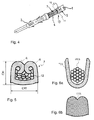
- contact specific crimp tools are used with a fixed crimp anvil down and vertically displaceable crimp punches above (see FIG. 1 to FIG. 3 ).
- the crimping die for the conductor crimp and the crimping die for the insulation crimp are mounted, which can usually be adjusted independently of one another in the vertical direction on the conductor diameter or insulation diameter by means of raster disks with different height cams. These settings directly affect the quality of the crimp connection.
- the cable feed takes place above the contact.
- the previously stripped conductor is usually positioned by machines simultaneously in the radial and axial direction relative to the contact correctly for the crimping process. Due to the downward movement of the crimping die, the conductor is first lowered via a mechanism into the upwardly opened conductor and insulation crimping claws, after which the actual crimping operation begins with forming the flaps corresponding to the crimping die shapes. After the stroke of the crimping die, the crimp has the desired compression molding (see FIG. 5 ), which in turn depends on the contact plate used, the conductor cross-section, the copper of the conductor and the stripping. When the contacts are closed, the conductor must be moved axially into the crimped area of the contact after the radial alignment.
- a sectional view of a faultless crimp connection shows the original single round Strands of the conductor compact to polygons pressed against each other.
- the inner surface in the crimp area of the contact shows deformations of the contact points of the individual strands.
- CCR crimp compression ratio
- a quality goal is to comply with a specific Crimp Compression Ratio CCR, regardless of which wire cross section is processed. This is achieved by specifying the appropriate crimp height for each conductor cross-section.
- crimp shape As Measure of crimp compression ratio and conductor pull-out strength.
- these criteria are only suitable when setting up the crimping machine and during sampling production.
- means In order to meet today's quality requirements for all crimp connections, means must be available which can record, evaluate and store crimp data via each crimp connection during the crimping process and influence machine data in a result-oriented manner.
- the crimping force is set in relation to the crimping path or the crimping time. With appropriate evaluation of the crimp data, the quality of a crimp connection can be reliably assessed.
- a method or device for assessing the quality of a crimped connection must detect crimped errors such as false insulation crimp height, wrong conductor crimp height, untreated strands in the conductor crimp, incorrect or no stripping length, incorrect insertion depth or strands cut off during stripping and generate corresponding error messages.
- a method for detecting missing strands or crimped conductor insulation in a crimp connection has become known from the crimp force characteristic.
- value pairs consisting of crimping force and position of the crimping die are measured and stored.
- the during the production of a crimped connection measured value pairs result in the crimp force curve of the crimping process with the crimping force as a function of the position of the crimping die.
- the curve section with a strong increase in force is linearized and a point determined from the average of the minimum and maximum crimping force. The point is compared to a reference value.
- the crimp connection is of acceptable quality.
- the maximum crimping force is also taken into account. If the maximum crimp force deviates excessively from a reference value, the crimped connection is rejected as unusable.
- the point in the curve section with a strong increase in force and the maximum crimping force provide information about missing strands or about crimped conductor insulation in the crimped connection.
- a force sensor detects the force during the crimping process, which is stored in digital form as a force-dependent curve. This is compared with a reference curve. Depending on the size of the deviation from the reference, the type of crimping error is determined.
- a disadvantage of this method is that despite a large computer, memory and computational effort no differentiated statement about the quality of the crimp connection is possible.
- a crimping device with a crimping known with the a contact can be connected to a conductor.
- the crimping device comprises a force sensor arranged above the crimping die in order to determine the crimping force.
- the crimp force curve is recorded and divided into several zones.
- the fourth zone width is multiplied by a factor between 0 and 2.
- the highest point on the reference crimp curve is normalized to 100%.
- the third zone width is then determined by the two 90% points on the reference crimp curve.
- An object of the invention is to provide a method and a device in which the abovementioned disadvantages are avoided and which lead to improved quality assurance.
- FIGS. 1 to 3 show a crimping process in which one end of a cable 1, from which protrudes a piece of conductor, is connected to a contact 2.
- An open crimping zone 3 of the contact 2 has a first double lug 4 for the insulation crimp 5 and a second double lug 6 for a conductor crimp 7.
- FIG. 1 shows Crimpstempel 8, 9 in the top dead center. The end of the conductor insulation lies in the first double lug 4 and the stripped cable piece lies in the second double lug 6.
- FIG. 2 will be shown at Lowering the crimping dies 8, 9, the double flaps 4, 6 by means of wedge-shaped recesses 10, which are located in the Crimpstempeln 8, 9, pressed against each other.
- FIG. 3 shows the finished crimp connection with the insulation crimp 5, in which the first double lug 4 is pressed around the conductor insulation 11, and with the conductor crimp 7, in which the second double lug 6 is pressed around the conductor.
- FIG. 4 shows a faultless crimped connection, in which in a window 13, the insulation 11 of the cable 1 and the individual strands of the conductor 12 are visible. At the contact-side end of the conductor crimps 7, the individual strands are visible again.
- FIG. 5 shows a good crimp connection 7 in cross section. After the stroke of the crimping dies 8, 9, the crimp 7 has the desired compression molding.
- FIG. 6a shows a contact and a conductor before crimping in cross-section.
- FIG. 6b shows the contact and the conductor after crimping in cross section.
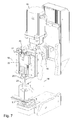
- FIG. 7 shows a possible embodiment of a crimping press in a three-dimensional view.
- the crimping press comprises a stand 14 which is in FIG. 7 partly broken up.
- a motor 15 is arranged with a gear 16.
- first guides 17 on which a ram 18 is guided.
- a driven by the gear 16 shaft 19 has at one end an eccentric pin.
- the ram 18 comprises a guided in the first guides 17 slider 22 and a tool holder 23 with force sensor 23.1.
- the slider 22 is in loose connection with the eccentric pin, wherein the rotational movement of the eccentric pin is converted into a linear movement of the slider 22.
- the position of the slider 22 and thus the ram 18 is detected with a linear sensor 20.
- the maximum stroke of the slider 22 is determined by the top dead center and the bottom dead center of the eccentric pin 21 (FIGS. 8 and 9 ) certainly.
- the tool holder 23 usually actuates the crimping tool 8, 9 (FIG. Fig. 1 ), which produces the crimped connection together with an anvil 9.1 belonging to the crimping tool.
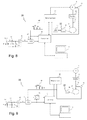
- FIG. 8 shows in a block diagram a first embodiment of a controller 28 together with parts of in FIG. 7 shown crimping press.
- the controller 28 is designed as a control loop and is used to control the crimping press.
- the control loop includes a motor controller 40, the motor 15, and an angle sensor 45 for detecting the rotational angle of the motor shaft.
- the crimping movement for a stroke is regulated by the motor controller 40 according to a predetermined speed-angle profile.
- the rotational movement is transmitted from the motor 15 to the gear 16 and then to the shaft 19, at one end of the eccentric pin 21 is arranged.
- the eccentric pin 21 puts the slider 22 of the ram 18 in a linear movement.
- the position of the slider 22 of the ram 18 is detected by the linear sensor 20.
- the linear sensor 20 comprises a scale with equidistant (distance .DELTA.s) arranged position markings, which are attached to the slider 22 of the ram 18.
- the linear sensor 20 includes a stationary read head. The linear sensor 20 generates an electrical voltage pulse 48 each time one of the position markers passes the read head.
- the force sensor 23.1 measures the force F. applied during the crimping process.
- the force sensor 23.1 is based on the piezoelectric effect and generates a charge q proportional to the force F.
- the proportionality factor is the charge constant k.
- a capacitor 43 with the capacitance C is connected in parallel with the force sensor 23.1 and forms a charge amplifier with a subsequent voltage amplifier 46.
- a discharge switch 44 is provided which discharges the charge of the capacitor 43 before each crimping cycle.
- a charge-amplifier downstream analog-to-digital converter 47 digitizes the output voltage u, which represents the applied force F, in synchronism with the position pulses 48 delivered by the linear sensor 20. From the digitized force F and the position pulses 48, the force-displacement curve of FIG Crimping process formed.
- a control unit 42 takes over the storage and evaluation of the force-displacement curve.
- FIG. 9 shows an alternative embodiment of the controller 28. This differs from the embodiment according to FIG. 8 on the one hand by the fact that the angle sensor 45 detects the angle of rotation ⁇ of the shaft 19 and for this purpose is in communication with the shaft 19. On the other hand, it differs from the embodiment according to FIG. 8 in that the position of the slider 22 is not offset by the linear sensor 20 (FIG. Fig. 8 ), but is detected by the angle sensor 45. With the aid of a corresponding transducer 50, the angle ⁇ delivered by the angle sensor 45 is transformed into a path s. The force-displacement curve of the crimping process is then formed from the digitized force F and the path s determined in this way.
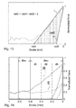
- FIG. 10a shows the force-angle curve, which was sampled with constant angular steps ⁇ .
- the 180 ° point on the abscissa with the angle ⁇ forms the bottom dead center of the ram 18. At this point, the force is maximum.
- s r ⁇ 1 + cos ⁇ the crimping path s is calculated from the angle ⁇ .
- r is the distance between the eccentric pin 21 and the center of the shaft 19th
- FIG. 10b shows the with this formula from the measured force-angle curve ( Fig. 10a ) derived force-displacement curve.
- the force-displacement curve is in a compression phase K and a decompression phase DK split.
- the zero point is right on the x-axis.
- FIG. 11 shows a diagram in which the course of the crimping force is shown depending on the way.
- This course is also called Crimpsignatur.
- the slider 22 of the ram 18 travels.
- the Crimpweg is also called Stroke.
- the force normalized to 1 is plotted on the y-axis.
- the force axis is normalized because the force sensor 23.1 (FIG. Fig. 7 ) does not have to be calibrated. Thus, it is sufficient if the force sensor 23.1 supplies a signal which, although proportional to the applied force F, is not absolutely scaled.
- the normalization of the force axis allows the use of a cost-effective, non-calibrated force sensor 23.1.
- the crimping path can be derived from the position signal 48 generated by the linear sensor 20.
- the crimping path can be derived from the rotational angle ⁇ of the shaft (eccentric axis) 19.
- the rotation angle ⁇ is measured with the angle sensor 45 and transformed with the transducer 50 into a path.
- the compression phase begins where the tabs 6 touch the conductor 12.
- the characteristic value csiA is also referred to below as the crimp signature index csiA.
- the area A is also referred to below as the compression area.
- FIG. 12 shows the same course of the crimping force as in FIG. 11 , but with a parameter csiB that indicates the width of the decompression phase.
- csiB 2 ⁇ B ⁇ 2
- a parameter csiB can be determined as a measure of the width of the decompression phase DK.
- the decompression phase DK begins after the eccentric pin 21 has reached the bottom dead center and ends when the crimping die 8,9 is removed from the contact 2.
- the characteristic value or value csiB is also referred to below as crimpsignature index csiB.
- B is the size of the area which is below the crimp force curve in the decompression phase DK.
- the area B is also referred to below as the decompression area.
- the value of the constant ⁇ is advantageously in the range of the constant force descent and is 0.8 in the present example.
- the crimpsignature index csiC corresponds to the area of the triangle with the baseline csiA - csiB and height 1. This area corresponds to the compression area of the crimp signature.
- the crimp signature index csiC can be used to monitor the crimp height CH.
- the crimp signature index csiD can be used to detect an error in setting up the crimping device. In particular, it can be detected with the crimp signature index csiD whether the conductor has been sufficiently stripped.
- csiE csiB ⁇ csiC
- the crimp signature index csiE is proportional to the compression work of the crimping operation, and thus is also proportional to the crimp compression ratio CCR: csiE ⁇ CCR
- the crimp signature index csiE can also be used to detect an error in setting up the crimping device.
- the crimpsignature index csiE can be used to check whether the crimp height CH set and the cable cross-section configured comply with the specifications.
- FIG. 14 shows a first Crimpkraftkurve R at a Referenzcrimp, which is also referred to below as Referenzimpimpkraftkurve R.
- FIG. 14 also shows a second crimp force curve E whose course is typical for a Leercrimp. Both crimp force curves R and E have the same evaluation zones Ziso and Zmc.
- the evaluation zone Zmc is additionally divided into three subzones Z1, Z2 and Z3.
- the Ziso evaluation zone is used to detect the crimping error "insulation in the crimp".
- the evaluation zone Zmc is used to detect the crimped error "Missing strands”.
- the evaluation zone Zmc covers as far as possible that section of the crimping force curve in which the compression of the strands takes place.
- the beginning of the evaluation zone Zmc should not lie before this compression range, because otherwise unnecessary noise components are evaluated. Therefore, the determination of the zone widths with the crimp signature index csiA, which, as mentioned above, marks the beginning of the compression phase.
- the evaluation zone Zmc is calculated as follows:
- the crimp height is monitored with the crimp signature index csiC.
- the crimp signature index csiC is determined during a crimping process and compared with a tolerance value chTol.
- FIG. 15 shows a typical force-displacement curve R for a faultless crimp and a typical force-displacement curve C1 for a faulty crimp with 10% missing strands.
- the error limit BLMC is also referred to as the error limit.
- the relative area difference Ri is thus the difference between the area f, which lies below the crimp force curve in the subzone Zi, and the reference area fref, which lies below the reference crimp force curve in the subzone Zi, divided by this reference area fref.
- the variance of the value Rmc is reduced and thus the discriminatory power for the detection of crimped errors is improved when the weighting factors Si are determined according to the relevance of the respective relative area difference Ri.
- the scaling factor ScaleFactorRmc is used to scale the value Rmc so that Rmc corresponds to the relative fraction of missing strands.
- the production is switched off, that is, no further crimping is performed. Instead, however, the crimp can also be marked as scrap without the production being stopped.
- the error limit BLMC MCL - a ⁇ Hours Rmc , for example, the factor a has the value 3.
- FIG. 16 clarifies these relationships.
- the value MCL specifies the percentage of missing strands that should be reliably detected.
- FIG. 16a a first distribution density function of the value of Rmc is shown.
- FIG. 16b shows a second distribution density function of Rmc.
- Rmc the relative frequency p
- the distribution density function of Rmc has the maximum at the mean of Rmc.
- the width of the distribution density function is defined by the variance of Rmc expressed by the standard deviation std (Rmc).
- the distribution density function of the Rmc values of the faultless crimps is designated pc.a and pc.b, respectively.
- the distribution density function of the Rmc values with MCL% mc missing strands is the FIGS. 16a and 16b denoted by fc.a or fc.b.
- the weighting factors Si are equal. It can be seen that the selectivity - expressed by the error limit BLMC - is insufficient for error detection due to the wide spread of the Rmc values is. Although the Rmc values of the faulty crimps (see distribution density function fc.a) are all smaller than the error limit -BLMC, the faulty crimps are recognized, but some of the Rmc values of the faultless crimps (see distribution density function pc.a) are also smaller than the error limit -BLMC and are thus erroneously classified as faulty.
- FIG. 16b shows the case where the weighting factors were determined as described above according to the relevance of the relative area differences Ri.
- the scattering of the Rmc values is smaller and the two distribution densities pc.b and fc.b do not overlap. Thus, a sufficient selectivity is given for.
- the faulty crimps are classified as bad and the flawless crimps as good.
- FIG. 15 In addition to the typical force-displacement curve for a faultless crimp R, a typical force-displacement curve for a faulty crimp with crimped insulation C2 is also shown.
- the relative area difference Riso from the zone Ziso with a limit value BLISO compared.
- the limit value BLISO is also referred to as the error limit.
- the relative area difference Riso is thus the difference between the area fiso, which lies below the crimping force curve C2 in the evaluation zone zio, and the reference area frefiso, which lies below the reference crimping force curve R in the zone zio, divided by this reference area frefiso.
- the crimp is marked as scrap.
- error limit BLISO is statistically calculated from the good crimpings.
- the setup with the subsequent automatic check can, for example, proceed as follows.
- the specified crimp height CH is set as follows. After a first crimp has been produced, the operator measures the crimp height CH and adjusts the crimping tool accordingly. This is repeated until the crimp height CH is within the tolerance.
- the setup is automatically checked. For this purpose, the current crimpsignature index csiE is compared with the process parameter csiE 0 stored in the database. If the difference between csiE and csiE 0 lies within the tolerance, ie the crimp height CH and the Conductor cross-section are OK, the production is released.
Abstract
Description
Die Erfindung betrifft ein Verfahren zur Bestimmung der Qualität einer Crimpverbindung zwischen einem Leiter und einem Kontakt, wobei eine Crimpeinrichtung eine Crimpkraft erzeugt, mittels welcher der Kontakt mit dem Leiter elektrisch und mechanisch unlösbar verbindbar sind.The invention relates to a method for determining the quality of a crimp connection between a conductor and a contact, wherein a crimping device generates a crimping force by means of which the contact with the conductor are electrically and mechanically non-detachably connectable.
Der Begriff "Crimpen" ist international eingeführt und normungstechnisch festgelegt. In der Praxis werden aber auch Ausdrücke wie Pressen, Quetschen, Anschlagen oder Ansetzen benutzt. Unter Crimpen versteht man die Herstellung einer nicht lösbaren elektrischen und mechanischen Verbindung zwischen einem Leiter und einem Kontakt. Beim Crimpvorgang wird das zu verbindende Material des Crimpkontakts und des Leiters plastisch, dauerhaft verformt. Dabei werden, falls vorhanden, schlecht leitende Oberflächenschichten aufgebrochen, was die elektrische Leitfähigkeiten begünstigt. Eine korrekte Crimpung verhindert aber auch das Eindringen korrosiver Medien selbst unter erschwerten Betriebsbedingungen wie Temperaturwechsel oder Vibration.The term "crimping" has been introduced internationally and defined in terms of standardization. In practice, however, terms such as pressing, squeezing, striking or piecing are used. Crimping is the production of a non-releasable electrical and mechanical connection between a conductor and a contact. During crimping, the material to be joined of the crimp contact and the conductor is plastically, permanently deformed. In this case, if present, poorly conducting surface layers are broken, which favors the electrical conductivities. Correct crimping also prevents the penetration of corrosive media even under difficult operating conditions such as temperature changes or vibration.
Ziel der Crimpung ist die Herstellung einer guten mechanischen und elektrischen Verbindung, die auf die Dauer qualitativ unverändert bleibt.The aim of the crimping is to produce a good mechanical and electrical connection, which remains qualitatively unchanged in the long run.
Zum Crimpen werden kontaktspezifische Crimpwerkzeuge verwendet mit einem feststehenden Crimpamboss unten und vertikal verschiebbaren Crimpstempeln oben (siehe
Bei offenen Crimpkontakten (siehe
Ein Schnittbild einer fehlerfrei ausgeführten Crimpverbindung zeigt die ursprünglich einzelnen runden Litzen des Leiters kompakt zu Vielecken gegeneinander gepresst. Die innere Fläche im Crimpbereich des Kontaktes zeigt Verformungen der Berührungsstellen der einzelnen Litzen.A sectional view of a faultless crimp connection shows the original single round Strands of the conductor compact to polygons pressed against each other. The inner surface in the crimp area of the contact shows deformations of the contact points of the individual strands.
Eine wichtige Kenngrösse für den Verpressungsgrad des Leitercrimps ist das Crimp Kompressions-Verhältnis CCR, definiert als Verhältnis von Querschnittfläche des gecrimpten Leitercrimps CCS zu der Summe der Querschnittflächen des Leiters WCS und des Kontaktteils TCS vor der Verformung. 
Ein Qualitätsziel ist es, ein bestimmtes Crimp-Kompressions-Verhältnis CCR einzuhalten, und zwar unabhängig davon welcher Leiterquerschnitt verarbeitetet wird. Dies wird erreicht, indem für jeden Leiterquerschnitt die entsprechende Crimphöhe vorgegeben wird.A quality goal is to comply with a specific Crimp Compression Ratio CCR, regardless of which wire cross section is processed. This is achieved by specifying the appropriate crimp height for each conductor cross-section.
Beim Leitercrimp müssen alle einzelnen Litzen umfasst sein. Am vorderen Ende des Leitercrimps müssen die einzelnen Litzen je nach Querschnitt etwa 0,5 mm herausragen und dürfen nicht im Crimp verschwinden. In dem zwischen dem Leitercrimp und dem Isolationscrimp liegenden Fenster müssen Leiter und Leiterisolation sichtbar sein. Der Isolationscrimp muss die Isolation umschliessen ohne in diese einzudringen.For conductor crimp, all individual strands must be included. At the front end of the conductor crimps, the individual strands have to protrude about 0.5 mm depending on the cross section and must not disappear in the crimp. The conductor and conductor insulation must be visible in the window between the conductor crimp and the insulation crimp. The insulation crimp must enclose the insulation without penetrating it.
Wichtige Kriterien für die Beurteilung einer Crimpverbindung sind die Crimpform, die Crimphöhe als Mass für das Crimp-Kompressions-Verhältnis und die Leiterausreiss-Festigkeit. Diese Kriterien eignen sich aber nur beim Einrichten der Crimpmaschine und während der Produktion bei Stichproben. Um den heutigen Qualitätsanforderungen für sämtliche Crimpverbindungen zu genügen, müssen Mittel zur Verfügung stehen, welche über jede Crimpverbindung während des Crimpvorganges Crimpdaten aufnehmen, auswerten, speichern und ergebnisorientiert Maschinendaten beeinflussen können. Zur Beurteilung der Crimpverbindung (ohne mechanische Zerstörung der Crimpverbindung) wird die Crimpkraft in Relation zum Crimpweg oder zur Crimpzeit gesetzt. Mit entsprechender Auswertung der Crimpdaten kann die Güte einer Crimpverbindung verlässlich beurteilt werden.Important criteria for the assessment of a crimp connection are the crimp shape, the crimp height as Measure of crimp compression ratio and conductor pull-out strength. However, these criteria are only suitable when setting up the crimping machine and during sampling production. In order to meet today's quality requirements for all crimp connections, means must be available which can record, evaluate and store crimp data via each crimp connection during the crimping process and influence machine data in a result-oriented manner. To evaluate the crimp connection (without mechanical destruction of the crimped connection), the crimping force is set in relation to the crimping path or the crimping time. With appropriate evaluation of the crimp data, the quality of a crimp connection can be reliably assessed.
Ein Verfahren beziehungsweise eine Einrichtung zur Beurteilung der Qualität einer Crimpverbindung muss Crimpfehler wie falsche Isolationscrimp-Höhe, falsche Leitercrimp-Höhe, nicht erfasste Litzen beim Leitercrimp, falsche oder keine Abisolierlänge, falsche Einlegetiefe oder beim Abisolieren abgeschnittene Litzen erkennen und entsprechende Fehlermeldungen erzeugen.A method or device for assessing the quality of a crimped connection must detect crimped errors such as false insulation crimp height, wrong conductor crimp height, untreated strands in the conductor crimp, incorrect or no stripping length, incorrect insertion depth or strands cut off during stripping and generate corresponding error messages.
Aus der Anmeldeschrift
Bei einer marktgängigen Crimppresse erfasst ein Kraftsensor während des Crimpvorganges die Kraft, die in digitaler Form als kraftabhängiger Kurvenverlauf abgespeichert wird. Dieser wird mit einer Referenzkurve verglichen. Je nach Grösse der Abweichung zur Referenz wird auf den Typ des Crimpfehlers geschlossen.In a standard crimping press, a force sensor detects the force during the crimping process, which is stored in digital form as a force-dependent curve. This is compared with a reference curve. Depending on the size of the deviation from the reference, the type of crimping error is determined.
Nachteilig bei diesem Verfahren ist, dass trotz grossem Rechner-, Speicher- und Rechenaufwand keine differenzierte Aussage über die Qualität der Crimpverbindung möglich ist.A disadvantage of this method is that despite a large computer, memory and computational effort no differentiated statement about the quality of the crimp connection is possible.
Zudem ist aus dem Stand der Technik
Um die Qualität der Crimpverbindung zu ermitteln, wird die Crimpkraftkurve aufgezeichnet und in mehrere Zonen aufgeteilt. Zur Bestimmung der Breite der ersten und der zweiten Zone wird die vierte Zonenbreite mit einem Faktor zwischen 0 und 2 multipliziert. Der höchste Punkt auf der Referenzcrimpkraftkurve wird auf 100% normiert. Die dritte Zonenbreite wird dann durch die beiden 90%-Punkte auf der Referenzcrimpkraftkurve bestimmt.To determine the quality of the crimp connection, the crimp force curve is recorded and divided into several zones. To determine the width of the first and second zones, the fourth zone width is multiplied by a factor between 0 and 2. The highest point on the reference crimp curve is normalized to 100%. The third zone width is then determined by the two 90% points on the reference crimp curve.
Hier will die Erfindung Abhilfe schaffen. Eine Aufgabe der Erfindung ist es, ein Verfahren und eine Vorrichtung anzugeben, bei denen die oben genannten Nachteile vermieden werden und die zu einer verbesserten Qualitätssicherung führen.The invention aims to remedy this situation. An object of the invention is to provide a method and a device in which the abovementioned disadvantages are avoided and which lead to improved quality assurance.
Die Aufgabe wird durch ein Verfahren mit den Merkmalen gemäss Patentanspruch 1 gelöst.The object is achieved by a method having the features according to
Zudem wird die Aufgabe durch eine Vorrichtung mit den Merkmalen gemäss den Patentansprüchen 11 und 12 gelöst.In addition, the object is achieved by a device having the features according to the
Die durch die Erfindung erreichten Vorteile sind im wesentlichen darin zu sehen, dass mit der besseren Auflösung der Fehler eine Qualitätssteigerung möglich ist, dass mit der sensibleren Fehlerdiagnose weniger Ausschuss entsteht und dass Folgefehler, beispielsweise eine Panne eines Personenwagens wegen Wackelkontaktes in einer Steckerverbindung vermieden werden.The advantages achieved by the invention are essentially to be seen in the fact that with the better resolution of the error an increase in quality is possible that with the more sensitive fault diagnosis less rejects and that subsequent error, for example a breakdown of a passenger car due to loose contact in a plug connection can be avoided.
Vorteilhafte Weiterbildungen der Erfindung ergeben sich aus den in den abhängigen Patentansprüchen angegebenen Merkmalen.Advantageous developments of the invention will become apparent from the features indicated in the dependent claims.
Im folgenden wird die Erfindung mit mehreren Ausführungsbeispielen anhand von mehreren Figuren weiter erläutert.
Figur 1- zeigt einen Kabel und einen Kontakt vor dem Crimpen.
Figur 2- zeigt das Kabel und den Kontakt während des Crimpens.
- Figur 3
- zeigt das Kabel und den Kontakt nach dem Crimpen.
- Figur 4
- zeigt eine Crimpverbindung zwischen dem Leiter und einem Kontakt.
Figur 5- zeigt die Crimpverbindung im Querschnitt.
- Figur 6a
- zeigt einen Kontakt und einen Leiter vor dem Crimpen im Querschnitt.
- Figur 6b
- zeigt den Kontakt und den Leiter nach dem Crimpen im Querschnitt.
- Figur 7
- zeigt eine Crimppresse in einer dreidimensionalen Ansicht.
Figur 8- zeigt ein Blockdiagramm einer ersten Ausführungsform einer Steuerung zusammen mit einem Teil der Crimppresse.
Figur 9- zeigt ein Blockdiagramm einer zweiten Ausführungsform der Steuerung zusammen mit einem Teil der Crimppresse.
- Figur 10a
- zeigt eine Kraft-Winkel-Kurve, die mit der Steuerung gemäss
Figur 9 aufgenommen wurde. - Figur 10b
- zeigt eine aus der Kraft-Winkel-Kurve gemäss
Figur 10 a) transformierte Kraft-Weg-Kurve. Figur 11- zeigt ein Diagramm, in dem der Verlauf der auf 1 normalisierten Crimpkraft in Abhängigkeit vom Weg dargestellt ist mit einem Parameter csiA, der den Beginn der Kompressionsphase kennzeichnet.
Figur 12- zeigt den gleichen Verlauf der Crimpkraft wie in
Figur 11 Figur 13- zeigt den gleichen Verlauf der Crimpkraft wie in
Figur 11 Figur 14- zeigt einen Verlauf der Crimpkraft, welcher in zwei Auswertezonen Ziso und Zmc unterteilt ist.
Figur 15- zeigt den Kraft-Weg-Verlauf für einen fehlerlosen Referenzcrimp R, einen fehlerhaften
Crimp C1 mit 10% fehlenden Litzen und einen fehlerhaften Crimp C2 mit eingecrimpter Isolation. - Figur 16a
- zeigt eine Verteilungsdichtefunktion für den Fall, dass die Gewichtungsfaktoren S1, S2 und S3 gleich gross sind.
- Figur 16b
- zeigt eine Verteilungsdichtefunktion für den Fall, dass die Gewichtungsfaktoren S1, S2 und S3 optimal gewählt wurden, so dass die Streuung der Rmc Werte minimal ist.
- FIG. 1
- shows a cable and a contact before crimping.
- FIG. 2
- shows the cable and contact during crimping.
- FIG. 3
- shows the cable and contact after crimping.
- FIG. 4
- shows a crimp connection between the conductor and a contact.
- FIG. 5
- shows the crimp in cross section.
- FIG. 6a
- shows a contact and a conductor before crimping in cross-section.
- FIG. 6b
- shows the contact and the conductor after crimping in cross section.
- FIG. 7
- shows a crimping press in a three-dimensional view.
- FIG. 8
- shows a block diagram of a first embodiment of a controller together with a part of the crimping press.
- FIG. 9
- shows a block diagram of a second embodiment of the controller together with a part of the crimping press.
- FIG. 10a
- shows a force-angle curve with the controller according to
FIG. 9 has been recorded. - FIG. 10b
- shows one from the force-angle curve according to
FIG. 10 a) transformed force-displacement curve. - FIG. 11
- shows a diagram in which the course of the normalized to 1 crimping force as a function of the path is shown with a parameter csiA, which marks the beginning of the compression phase.
- FIG. 12
- shows the same course of the crimping force as in
FIG. 11 , but with a parameter csiB that indicates the width of the decompression phase. - FIG. 13
- shows the same course of the crimping force as in
FIG. 11 , but with a parameter csiC, which identifies the area of the compression. - FIG. 14
- shows a course of the crimping force, which is divided into two evaluation zones Ziso and Zmc.
- FIG. 15
- shows the force-displacement curve for a faultless reference crimp R, a faulty crimp C1 with 10% missing strands and a faulty crimp C2 with crimped insulation.
- FIG. 16a
- shows a distribution density function in the case that the weighting factors S1, S2 and S3 are equal.
- FIG. 16b
- shows a distribution density function in the case that the weighting factors S1, S2 and S3 have been optimally selected, so that the dispersion of the Rmc values is minimal.
Die
Die Position des Gleitstücks 22 der Ramme 18 wird vom Linearsensor 20 erfasst. Der Linearsensor 20 umfasst einen Massstab mit äquidistant (Abstand Δs) angeordneten Positionsmarkierungen, welche am Gleitstück 22 der Ramme 18 angebracht sind. Zudem umfasst der Linearsensor 20 einen stationären Lesekopf. Der Linearsensor 20 erzeugt jeweils einen elektrischen Spannungsimpuls 48, wenn eine der Positionsmarkierungen den Lesekopf passiert.The position of the
Der Kraftsensor 23.1 misst die während des Crimpvorgangs für die Umformung aufgewendete Kraft F. Der Kraftsensor 23.1 basiert auf dem piezoelektrischen Effekt und erzeugt eine Ladung q, die proportional zur Kraft F ist. Der Proportionalitätsfaktor ist die Ladungskonstante k. Ein Kondensator 43 mit der Kapazität C ist zum Kraftsensor 23.1 parallel geschaltet und bildet mit einem nachfolgenden Spannungsverstärker 46 einen Ladungsverstärker. Die Ausgangsspannung u am Ausgang des Ladungsverstärkers beträgt: 
wobei g der Verstärkungsfaktor des Spannungsverstärkers 46 ist.
Zudem ist ein Entladeschalter 44 vorgesehen, der die Ladung des Kondensators 43 vor jedem Crimpzyklus entlädt. Ein dem Ladungsverstärker nachgeschalteter Analog-Digitalwandler 47 digitalisiert die Ausgangsspannung u, welche die aufgewendete Kraft F repräsentiert, synchron zu den vom Linearsensor 20 gelieferten Positionsimpulsen 48. Aus der digitalisierten Kraft F und den Positionsimpulsen 48 wird die Kraft-Weg-Kurve des Crimpvorganges gebildet. Eine Steuereinheit 42 übernimmt die Speicherung und Auswertung der Kraft-Weg-Kurve.The force sensor 23.1 measures the force F. applied during the crimping process. The force sensor 23.1 is based on the piezoelectric effect and generates a charge q proportional to the force F. The proportionality factor is the charge constant k. A
where g is the gain of the voltage amplifier 46.
In addition, a discharge switch 44 is provided which discharges the charge of the

Der Crimpweg kann aus dem vom Linearsensor 20 erzeugten Positionssignal 48 abgeleitet werden.The crimping path can be derived from the
Wenn die Crimppresse nicht über einen Linearsensor 20 verfügt, kann der Crimpweg aus dem Drehwinkel ε der Welle (Exzenterachse) 19 abgeleitet werden. Dazu wird mit dem Winkelsensor 45 der Drehwinkel ε gemessen und mit dem Wandler 50 in einen Weg transformiert.If the crimping press does not have a
Dabei ist A eine Fläche, die in der Kompressionsphase unter der Crimpkraftkurve liegt, bei einer normalisierten Kraft von 1 - γ beginnt und sich bis zur Spitzenkraft Fp = 1 erstreckt. Die Fläche A wird im Folgenden auch als Kompressionsfläche bezeichnet. γ ist eine Konstante, die vorteilhafter Weise so gewählt wird, dass ihr Wert im Bereich des konstanten Kraftanstiegs liegt. Im vorliegenden Beispiel ist γ = 0,5.Here, A is an area which is below the crimp force curve in the compression phase, starts at a normalized force of 1 - γ, and extends to the peak force Fp = 1. The area A is also referred to below as the compression area. γ is a constant that is advantageously chosen so that its value is in the range of the constant force increase. In the present example, γ = 0.5.

Dabei ist B die Grösse der Fläche, die in der Dekompressionsphase DK unter der Crimpkraftkurve liegt. Die Fläche B wird im Folgenden auch als Dekompressionsfläche bezeichnet. Der Wert der Konstante γ liegt vorteilhafter Weise im Bereich des konstanten Kraftabstiegs und ist im vorliegenden Beispiel 0,8.Here, B is the size of the area which is below the crimp force curve in the decompression phase DK. The area B is also referred to below as the decompression area. The value of the constant γ is advantageously in the range of the constant force descent and is 0.8 in the present example.
Wird beispielsweise die Konstante γ zu γ = 0,8 gewählt, beginnt die Fläche B bei einer normalisierten Kraft von 1 - γ = 0,2 und erstreckt sich bis zur Spitzenkraft Fp = 1.For example, if the constant γ is chosen to be γ = 0.8, the surface B starts at a normalized force of 1-γ = 0.2 and extends to the peak force Fp = 1.
Es gilt: 
wobei k eine Konstante ist.
Da der Crimpsignatur-Index csiB proportional zur Spitzenkraft Fp ist gilt: ![]()
Aus den Werten csiA und csiB berechnet sich ein weiterer Crimpsignatur-Index csiC: 
where k is a constant.
Since the crimp signature index csiB is proportional to the peak force Fp, the following applies: ![]()
From the values csiA and csiB another crimpsignature index csiC is calculated:
Wie in
Der Crimpsignatur-Index csiC kann zur Überwachung der Crimphöhe CH verwendet werden. Eine kleine Veränderung ΔCH der Crimphöhe CH bewirkt eine gleich grosse Veränderung ΔcsiC des Crimpsignatur-Indexes csiC mit umgekehrtem Vorzeichen. Es gilt also: ![]()
Aus den Crimpsignatur-Indizes csiC und csiB berechnet sich ein weiterer Crimpsignatur-Index csiD: 
![]()
The crimpsignature indices csiC and csiB are used to calculate another crimpsignature index csiD:
Der Crimpsignatur-Index csiD kann zur Erkennung eines Fehlers beim Einrichten der Crimpvorrichtung verwendet werden. Insbesondere kann mit dem Crimpsignatur Index csiD erkannt werden, ob der Leiter ausreichend abisoliert wurde.The crimp signature index csiD can be used to detect an error in setting up the crimping device. In particular, it can be detected with the crimp signature index csiD whether the conductor has been sufficiently stripped.
Aus den Werten csiB und csiC berechnet sich ein weiterer Crimpsignatur-Index csiE: 
Der Crimpsignatur-Index csiE ist proportional zur Kompressionsarbeit des Crimpvorgangs, und ist somit auch proportional zum Crimp Kompressions-Verhältnis CCR: ![]()
The crimp signature index csiE is proportional to the compression work of the crimping operation, and thus is also proportional to the crimp compression ratio CCR: ![]()
Der Crimpsignatur-Index csiE kann ebenfalls zur Erkennung eines Fehlers beim Einrichten der Crimpvorrichtung verwendet werden. Insbesondere kann mit dem Crimpsignatur-Index csiE überprüft werden, ob die eingestellte Crimphöhe CH und der eingerichtete Kabelquerschnitt den Spezifikationen entsprechen.The crimp signature index csiE can also be used to detect an error in setting up the crimping device. In particular, the crimpsignature index csiE can be used to check whether the crimp height CH set and the cable cross-section configured comply with the specifications.
Im Folgenden wird unter Bezugnahme auf
Die Auswertezone Ziso wird herangezogen, um den Crimpfehler "Isolation im Crimp" zu erkennen. Die Auswertezone Zmc hingegen wird herangezogen, um den Crimpfehler "Fehlende Litzen" zu erkennen.The Ziso evaluation zone is used to detect the crimping error "insulation in the crimp". By contrast, the evaluation zone Zmc is used to detect the crimped error "Missing strands".
Um den Crimpfehler "Fehlende Litzen" zu erkennen, ist es von Vorteil, wenn die Auswertezone Zmc möglichst denjenigen Abschnitt der Crimpkraftkurve abdeckt, in dem die Komprimierung der Litzen erfolgt. Der Beginn der Auswertezone Zmc sollte aber nicht vor diesem Komprimierungsbereich liegen, weil sonst unnötige Rauschanteile ausgewertet werden. Deshalb erfolgt die Festlegung der Zonenbreiten mit dem Crimpsignatur-Index csiA, der, wie oben erwähnt, den Beginn der Kompressionsphase kennzeichnet.In order to detect the crimping error "missing strands", it is advantageous if the evaluation zone Zmc covers as far as possible that section of the crimping force curve in which the compression of the strands takes place. However, the beginning of the evaluation zone Zmc should not lie before this compression range, because otherwise unnecessary noise components are evaluated. Therefore, the determination of the zone widths with the crimp signature index csiA, which, as mentioned above, marks the beginning of the compression phase.

wobei W ein Parameter ist, der im Bereich von W = 0,5 bis 2,0 liegt und für den standardmässig W = 1 gilt.
where W is a parameter that is in the range of W = 0.5 to 2.0 and for which W = 1 by default.
Die Teilzonen Z1, Z2 und Z3 werden wie folgt bestimmt: 
Die Auswertezone Ziso wird wie folgt bestimmt: ![]()
![]()
Überwachung der Crimphöhe während der laufenden ProduktionMonitoring the crimp height during ongoing production
Die Crimphöhe wird mit dem Crimpsignaturindex csiC überwacht. Dazu wird der Crimpsignaturindex csiC während eines Crimpvorgangs ermittelt und mit einem Toleranzwert chTol verglichen.The crimp height is monitored with the crimp signature index csiC. For this purpose, the crimp signature index csiC is determined during a crimping process and compared with a tolerance value chTol.
Für den Fall, dass die Crimphöhe und damit der Crimpsignaturindex csiC des aktuell zu überprüfenden Crimps von der Referenz-Crimphöhe zu stark abweicht, das heisst den Toleranzwert chTol überschreitet, wird die Produktion abgeschaltet, das heisst es werden keine weiteren Crimpungen mehr durchgeführt.In the event that the crimp height and thus the crimp signature index csiC of the crimp to be tested currently deviates too much from the reference crimp height, ie exceeds the tolerance value chTol, the production is switched off, ie no further crimping is carried out.
Mit der erfindungsgemässen Lösung kann erkannt werden, ob und auch wie viele Litzen eines Leiters 12 (
Zur Fehlererkennung wird zunächst ein Wert Rmc, der den relativen Anteil fehlender Litzen angibt und im Folgenden auch als Resultat bezeichnet wird, wie folgt berechnet: 
wobei gilt:
- ScaleFactorRmc ist ein Skalierungsfaktor,
- Si ist der Gewichtungsfaktor für die Teilzone Zi und
- Ri ist die relative Flächendifferenz für die Teilzone Zi.
where:
- ScaleFactorRmc is a scaling factor
- Si is the weighting factor for subzone Zi and
- Ri is the relative area difference for subzone Zi.
Anschliessend wird der Wert Rmc mit einem Fehlergrenzwert BLMC verglichen. Der Fehlergrenzwert BLMC wird auch als Fehlergrenze bezeichnet.Subsequently, the value Rmc is compared with an error limit BLMC. The error limit BLMC is also referred to as the error limit.
Die relative Flächendifferenz Ri einer Teilzone Zi berechnet sich nach folgender Formel: 
wobei f die Fläche ist, die unter der Crimpkraftkurve in der Teilzone Zi liegt, und fRef die Referenzfläche ist, die unter der Referenzcrimpkraftkurve in der Teilzone Zi liegt.The relative area difference Ri of a subzone Zi is calculated according to the following formula:
where f is the area which is below the crimp force curve in subzone Zi, and fRef is the reference area which is below the reference crimp force curve in subzone Zi.
Die relative Flächendifferenz Ri ist also die Differenz zwischen der Fläche f, die unter der Crimpkraftkurve in der Teilzone Zi liegt, und der Referenzfläche fRef, die unter der Referenzcrimpkraftkurve in der Teilzone Zi liegt, dividiert durch diese Referenzfläche fRef.The relative area difference Ri is thus the difference between the area f, which lies below the crimp force curve in the subzone Zi, and the reference area fref, which lies below the reference crimp force curve in the subzone Zi, divided by this reference area fref.
Die Streuung des Wertes Rmc wird verringert und somit die Trennschärfe für die Erkennung von Crimpfehler verbessert, wenn die Gewichtungsfaktoren Si entsprechend der Relevanz der jeweiligen relativen Flächendifferenz Ri bestimmt werden. Die Gewichtungsfaktoren Si berechnen sich nach folgender Formel: 
wobei Ri(ec) die relative Flächendifferenz der Teilzone Zi für einen Leercrimp ec und std(Ri) die Standardabweichung von Ri, ermittelt über eine grössere Anzahl von fehlerlosen Crimps, ist.The variance of the value Rmc is reduced and thus the discriminatory power for the detection of crimped errors is improved when the weighting factors Si are determined according to the relevance of the respective relative area difference Ri. The weighting factors Si are calculated according to the following formula:
where Ri (ec) is the relative area difference of subzone Zi for an empty crimp ec and std (Ri) is the standard deviation of Ri, determined over a larger number of faultless crimps.
Der Skalierungsfaktor ScaleFactorRmc dient zur Skalierung des Wertes Rmc, so dass Rmc dem relativen Anteil fehlenden Litzen entspricht.The scaling factor ScaleFactorRmc is used to scale the value Rmc so that Rmc corresponds to the relative fraction of missing strands.
Zur Bestimmung des Skalierungsfaktors ScaleFacorRmc wird ein Fehlcrimp mit einem definierten Anteil mc % fehlender Litzen ausgeführt. Fehlen beispielsweise 2 von 19 Litzen ergibt sich der Wert mc zu mc = 2 / 19 * 100 = 10.5 %. Wird beispielsweise ein Leercrimp durchgeführt, das heisst es wird ein Kontakt ohne Leiter gecrimpt, ergibt sich der Wert mc zu mc = 1 / 1 * 100 = 100 %. Der Skalierungsfaktor ScaleFacorRmc wird nun so bestimmt, dass das Resultat dieses Fehlcrimps Rmc = -mc % ergibt.To determine the scaling factor ScaleFacorRmc, a false crimp is performed with a defined percentage mc% of missing strands. If, for example, 2 of 19 strands are missing, the value mc becomes mc = 2/19 * 100 = 10.5%. If, for example, an empty crimp is performed, ie if a contact is crimped without a conductor, the value mc becomes mc = 1/1 * 100 = 100%. The scaling factor ScaleFacorRmc is now determined so that the result of this error crimps Rmc = -mc%.
Für den Fall, dass das Resultat Rmc beim aktuell zu überprüfenden Crimp die Fehlergrenze -BLMC unterschreitet, wird beispielsweise die Produktion abgeschaltet, das heisst es werden keine weiteren Crimpungen mehr durchgeführt. Statt dessen kann aber auch der Crimp als Ausschuss gekennzeichnet werden ohne dass die Produktion gestoppt wird.In the event that the result Rmc falls below the error limit -BLMC for the crimp to be tested, for example, the production is switched off, that is, no further crimping is performed. Instead, however, the crimp can also be marked as scrap without the production being stopped.
Um die Fehlergrenze BLMC zu bestimmen, werden mehrere Crimpungen durchgeführt. Anschliessend wird aus den guten Crimpungen die Standardabweichung std(Rmc) der Rmc Resultate berechnet. Weiter wird der geforderte Anteil von fehlenden Litzen in Prozent mit dem Wert MCL vorgegeben. Wird als Wert MCL zum Beispiel MCL = 10% vorgegeben, heisst das, dass das System 10% fehlende Litzen sicher erkennen soll. Die Fehlergrenze BLMC berechnet sich nun zu: ![]()
wobei der Faktor a zum Beispiel den Wert 3 hat.To determine the error limit BLMC, multiple crimping is performed. Then the standard deviation std (Rmc) of the Rmc results is calculated from the good crimps. Furthermore, the required percentage of missing strands is specified in percent with the value MCL. For example, if MCL is set to MCL = 10%, that means the system will have 10% missing Should identify strands safely. The error limit BLMC is now calculated as: ![]()
for example, the factor a has the value 3.
Bei den Verteilungsdichtefunktionen fc.a und pc.a gemäss
Ein weiterer möglicher Fehler beim Crimpen kann sein, dass sich zwischen dem Kontakt 2 (
Um einen Crimp mit eingecrimpter Isolation als fehlerhaft erkennen zu können, wird die relative Flächendifferenz Riso aus der Zone Ziso mit einem Grenzwert BLISO verglichen. Der Grenzwert BLISO wird auch als Fehlergrenze bezeichnet.In order to be able to recognize a crimp with crimped insulation as faulty, the relative area difference Riso from the zone Ziso with a limit value BLISO compared. The limit value BLISO is also referred to as the error limit.
Die relative Flächendifferenz Riso berechnet sich wie folgt: 
Die relative Flächendifferenz Riso ist also die Differenz zwischen der Fläche fiso, die unter der Crimpkraftkurve C2 in der Auswertezone Ziso liegt, und der Referenzfläche fRefiso, die unter der Referenzcrimpkraftkurve R in der Zone Ziso liegt, dividiert durch diese Referenzfläche fRefiso.The relative area difference Riso is thus the difference between the area fiso, which lies below the crimping force curve C2 in the evaluation zone ziso, and the reference area frefiso, which lies below the reference crimping force curve R in the zone ziso, divided by this reference area frefiso.
Für den Fall, dass die relative Flächendifferenz Riso beim aktuell zu überprüfenden Crimp den Flächengrenzwert BLISO überschreitet, wird beispielsweise der Crimp als Ausschuss gekennzeichnet.For example, if the relative area difference Riso in the crimp to be checked exceeds the area limit BLISO, the crimp is marked as scrap.
Um die Fehlergrenze BLISO zu bestimmen, werden mehrere Crimpungen durchgeführt. Anschliessend wird aus den guten Crimpungen statistisch die Fehlergrenze BLISO berechnet.To determine the error limit BLISO, several crimps are performed. Then the error limit BLISO is statistically calculated from the good crimpings.
Bevor eine Crimpverbindung zum ersten Mal verarbeitet werden kann, müssen zuvor einmalig die Prozessparameter ermittelt werden. Diese werden dann in einer Datenbank abgelegt und können jeweils bei der Produktion der entsprechenden Crimpverbindung abgerufen werden. Zu den Prozessparametern gehören:
- Die Crimpsignatur-Indizes csiA0, csiB0, csic0, csiD0 und csiE0.
- Die Fehlergrenzen BLMC und BLISO.
- Die Gewichtungsfaktoren S1, S2 und S3.
- Der Skalierungsfaktor ScaleFactorRmc.
- The Crimpsignatur indices csiA 0 , csiB 0 , csic 0 , csiD 0 and csiE 0 .
- The error limits BLMC and BLISO.
- The weighting factors S1, S2 and S3.
- The scaling factor ScaleFactorRmc.
Beim Einrichten des Crimp-Prozesses auf dem Crimpautomaten muss sichergestellt werden, dass die Crimpverbindung den Spezifikationen entspricht. Insbesondere muss überprüft werden, ob der vorgeschriebene Kabelquerschnitt verarbeitet wird und ob die Crimpverbindung die spezifizierte Crimphöhe CH aufweist.When setting up the crimping process on the crimping machine, make sure that the crimping connection meets the specifications. In particular, it must be checked whether the prescribed cable cross-section is processed and whether the crimp connection has the specified crimp height CH.
Das Einrichten mit der anschliessenden automatischen Überprüfung kann zum Beispiel folgendermassen ablaufen. In einem ersten Schritt wird die spezifizierte Crimphöhe CH wie folgt eingestellt. Nachdem ein erster Crimp produziert worden ist misst die Bedienperson die Crimphöhe CH und stellt das Crimpwerkzeug entsprechend nach. Dies wird solange wiederholt, bis die Crimphöhe CH innerhalb der Toleranz liegt. In einem zweiten Schritt wird das Einrichten automatisch überprüft. Dazu wird der aktuelle Crimpsignatur-Index csiE mit dem in der Datenbank hinterlegten Prozessparameter csiE0 verglichen. Liegt die Differenz zwischen csiE und csiE0 innerhalb der Toleranz, das heisst die Crimphöhe CH und der Leiterquerschnitt sind in Ordnung, wird die Produktion freigegeben.The setup with the subsequent automatic check can, for example, proceed as follows. In a first step, the specified crimp height CH is set as follows. After a first crimp has been produced, the operator measures the crimp height CH and adjusts the crimping tool accordingly. This is repeated until the crimp height CH is within the tolerance. In a second step, the setup is automatically checked. For this purpose, the current crimpsignature index csiE is compared with the process parameter csiE 0 stored in the database. If the difference between csiE and csiE 0 lies within the tolerance, ie the crimp height CH and the Conductor cross-section are OK, the production is released.
Die vorhergehende Beschreibung der Ausführungsbeispiele gemäss der vorliegenden Erfindung dient nur zu illustrativen Zwecken und nicht zum Zwecke der Beschränkung der Erfindung. Im Rahmen der Erfindung sind verschiedene Änderungen, Kombinationen der Ausführungsformen und Modifikationen möglich, ohne den Umfang der Erfindung sowie ihre Äquivalente zu verlassen.The foregoing description of the embodiments according to the present invention is for illustrative purposes only, and not for the purpose of limiting the invention. Within the scope of the invention, various changes, combinations of the embodiments and modifications are possible without departing from the scope of the invention and its equivalents.
- 11
- Kabelelectric wire
- 22
- KontaktContact
- 33
- Crimpzonecrimp
- 44
- Doppellaschedouble strap
- 55
- Isolationscrimpinsulation crimp
- 66
- Doppellaschedouble strap
- 77
- Leitercrimpconductor crimp
- 88th
- Crimpstempelcrimping dies
- 99
- Crimpstempelcrimping dies
- 9.19.1
- Ambossanvil
- 1010
- Ausnehmungrecess
- 1111
- Leiterisolationinsulation
- 1212
- Leiterladder
- 1313
- Fensterwindow
- 1414
- Ständerstand
- 1515
- Motorengine
- 1616
- Getriebetransmission
- 1717
- Führungguide
- 1818
- Rammeram
- 1919
- Wellewave
- 2020
- LinearmesssystemLinear measuring system
- 2121
- Exzenterzapfeneccentric
- 2222
- Gleitstückslide
- 2323
- Werkzeughaltertoolholder
- 23.123.1
- Kraftsensorforce sensor
- 2828
- Steuerungcontrol
- 4040
- Motorreglermotor controller
- 4141
- Steuerungseinheitcontrol unit
- 4242
- Externer ComputerExternal computer
- 4343
- Kondensatorcapacitor
- 4444
- Entladungsschalterdischarge switch
- 4545
- Winkelsensorangle sensor
- 4646
- Spannungs-VerstärkerVoltage amplifier
- 4747
- Analog - Digital WandlerAnalog - digital converter
- 4848
- Impulsfolge der Weg-InkrementePulse train of the path increments
- 4949
- Impulsfolge der Winkel-InkrementePulse train of angular increments
- 5050
- Winkel zu Weg TransformationseinheitAngle to path transformation unit
- TCSTCS
- Querschnittsfläche des KontaktsCross-sectional area of the contact
- WCSWCS
- Querschnittsfläche des LeitersCross sectional area of the conductor
- CCSCCS
- Querschnittsfläche des LeitercrimpsCross sectional area of the conductor crimp
- CHCH
- Crimphöhecrimp height
- ZisoZiso
- Auswertezoneevaluation zone
- ZmcZmc
- Auswertezoneevaluation zone
- Z1Z1
- Teilzonesubzone
- Z2Z2
- Teilzonesubzone
- Z3Z3
- Teilzonesubzone
- KK
- Kompressionsphasecompression phase
- DKDK
- Dekompressionsphasedecompression
- RR
- ReferenzcrimpkurveReferenzcrimpkurve
- FF
- Crimpkraftcrimping force
- C1C1
- Crimpkurvecrimping curve
- C2C2
- Crimpkurvecrimping curve
- Ee
- Crimpkurvecrimping curve
Claims (12)
Priority Applications (1)
| Application Number | Priority Date | Filing Date | Title |
|---|---|---|---|
| EP09172082.1A EP2173015B1 (en) | 2008-10-02 | 2009-10-02 | Method for calculating the quality of a crimp connection between a conductor and a contact |
Applications Claiming Priority (2)
| Application Number | Priority Date | Filing Date | Title |
|---|---|---|---|
| EP08165675 | 2008-10-02 | ||
| EP09172082.1A EP2173015B1 (en) | 2008-10-02 | 2009-10-02 | Method for calculating the quality of a crimp connection between a conductor and a contact |
Publications (2)
| Publication Number | Publication Date |
|---|---|
| EP2173015A1 true EP2173015A1 (en) | 2010-04-07 |
| EP2173015B1 EP2173015B1 (en) | 2017-05-03 |
Family
ID=40351547
Family Applications (1)
| Application Number | Title | Priority Date | Filing Date |
|---|---|---|---|
| EP09172082.1A Active EP2173015B1 (en) | 2008-10-02 | 2009-10-02 | Method for calculating the quality of a crimp connection between a conductor and a contact |
Country Status (3)
| Country | Link |
|---|---|
| US (1) | US8746026B2 (en) |
| EP (1) | EP2173015B1 (en) |
| CN (1) | CN101713648B (en) |
Cited By (4)
| Publication number | Priority date | Publication date | Assignee | Title |
|---|---|---|---|---|
| WO2012110310A1 (en) * | 2011-02-17 | 2012-08-23 | Robert Bosch Gmbh | Method and device for the quality-assuring production of a crimp |
| EP2821215A1 (en) * | 2013-06-13 | 2015-01-07 | Otto Bihler Handels-Beteiligungs-GmbH | Forming method with control of a geometric characteristic of a workpiece and device for the same |
| AT515783B1 (en) * | 2014-06-06 | 2015-12-15 | Avl List Gmbh | METHOD FOR MANUFACTURING AN ELECTRIC ENERGY STORAGE |
| DE102015104161A1 (en) | 2015-03-19 | 2016-09-22 | Lisa Dräxlmaier GmbH | Method and device for monitoring a crimping device |
Families Citing this family (14)
| Publication number | Priority date | Publication date | Assignee | Title |
|---|---|---|---|---|
| US8904616B2 (en) | 2009-04-09 | 2014-12-09 | Schleuniger Holding Ag | Method of monitoring a crimping process, crimping press and computer program product |
| EP2417676B1 (en) * | 2009-04-09 | 2013-03-06 | Schleuniger Holding AG | Method of monitoring a crimping process, crimping press and computer program product |
| EP2378615A1 (en) * | 2010-04-13 | 2011-10-19 | Schleuniger Holding AG | Crimp press |
| US9331447B2 (en) * | 2010-12-07 | 2016-05-03 | Tyco Electronics Corporation | Crimping apparatus having a crimp quality monitoring system |
| US20120263344A1 (en) * | 2011-04-12 | 2012-10-18 | Stefan Viviroli | Measuring apparatus and method for determining at least of the crimp height of a conductor crimp |
| TWI608677B (en) * | 2012-08-15 | 2017-12-11 | 威查格工具廠有限公司 | Exchanging adapter for a crimp machine |
| US10581213B2 (en) * | 2017-04-25 | 2020-03-03 | Te Connectivity Corporation | Crimp tooling having guide surfaces |
| US10566755B2 (en) * | 2017-04-25 | 2020-02-18 | Te Connectivity Corporation | Crimp tooling for terminal crimping machine |
| US10522960B2 (en) | 2017-05-03 | 2019-12-31 | Te Connectivity Corporation | Crimp quality monitoring method and system for use with a hydraulic crimping apparatus |
| CN109655242A (en) * | 2017-10-10 | 2019-04-19 | 中国商用飞机有限责任公司 | For detecting the method and apparatus for the reliability that harness is connect with termination case |
| ES2880751T3 (en) | 2018-09-10 | 2021-11-25 | Hoefliger Harro Verpackung | Universal rolling machine for a multitude of tray designs |
| DE102018218371A1 (en) * | 2018-10-26 | 2020-04-30 | Schäfer Werkzeug- und Sondermaschinenbau GmbH | Method for monitoring a crimping device, monitoring unit and crimping device |
| DE102019101016A1 (en) * | 2019-01-16 | 2020-07-16 | Harting Electric Gmbh & Co. Kg | Method and device for checking the quality of a crimp |
| CN110749843A (en) * | 2019-09-18 | 2020-02-04 | 苏州经纬通电子科技有限公司 | Wire harness terminal crimping height standard calculation method and system |
Citations (4)
| Publication number | Priority date | Publication date | Assignee | Title |
|---|---|---|---|---|
| DE4014221A1 (en) * | 1989-05-12 | 1990-11-15 | Siemens Ag | Production monitoring of crimped electrical connectors - using built in strain gauge to measure load as indication of crimping quality |
| EP0460441A1 (en) | 1990-05-29 | 1991-12-11 | The Whitaker Corporation | Method of determining the quality of a crimped electrical connection |
| EP0902509A1 (en) * | 1997-09-11 | 1999-03-17 | Komax Holding Ag | Method and apparatus for determinating the quality of a crimped connection |
| EP1071174A2 (en) * | 1999-07-23 | 2001-01-24 | Yazaki Corporation | Terminal crimping quality decision method/device |
Family Cites Families (4)
| Publication number | Priority date | Publication date | Assignee | Title |
|---|---|---|---|---|
| DE59813281D1 (en) * | 1997-09-11 | 2006-01-19 | Komax Holding Ag Dierikon | Method and device for determining the quality of a crimp connection |
| DE19843156A1 (en) * | 1998-09-21 | 2000-04-20 | Sle Electronic Gmbh | Process for quality assurance of crimp connections produced in a crimping device, as well as crimping tool and crimping device |
| US6152188A (en) * | 1999-04-09 | 2000-11-28 | Teknika Usa, Inc. | Crimping device |
| JP4031214B2 (en) * | 2001-03-19 | 2008-01-09 | 矢崎総業株式会社 | Terminal crimping state identification method |
-
2009
- 2009-09-10 US US12/556,661 patent/US8746026B2/en active Active
- 2009-09-27 CN CN200910178541.2A patent/CN101713648B/en active Active
- 2009-10-02 EP EP09172082.1A patent/EP2173015B1/en active Active
Patent Citations (5)
| Publication number | Priority date | Publication date | Assignee | Title |
|---|---|---|---|---|
| DE4014221A1 (en) * | 1989-05-12 | 1990-11-15 | Siemens Ag | Production monitoring of crimped electrical connectors - using built in strain gauge to measure load as indication of crimping quality |
| EP0460441A1 (en) | 1990-05-29 | 1991-12-11 | The Whitaker Corporation | Method of determining the quality of a crimped electrical connection |
| EP0902509A1 (en) * | 1997-09-11 | 1999-03-17 | Komax Holding Ag | Method and apparatus for determinating the quality of a crimped connection |
| EP0902509B1 (en) | 1997-09-11 | 2003-01-22 | Komax Holding Ag | Method for determinating the quality of a crimped connection |
| EP1071174A2 (en) * | 1999-07-23 | 2001-01-24 | Yazaki Corporation | Terminal crimping quality decision method/device |
Cited By (8)
| Publication number | Priority date | Publication date | Assignee | Title |
|---|---|---|---|---|
| WO2012110310A1 (en) * | 2011-02-17 | 2012-08-23 | Robert Bosch Gmbh | Method and device for the quality-assuring production of a crimp |
| CN103370841A (en) * | 2011-02-17 | 2013-10-23 | 罗伯特·博世有限公司 | Method and device for the quality-assuring production of a crimp |
| KR101554651B1 (en) | 2011-02-17 | 2015-09-21 | 로베르트 보쉬 게엠베하 | Method and device for the quality-assuring production of a crimp |
| CN103370841B (en) * | 2011-02-17 | 2016-08-17 | 罗伯特·博世有限公司 | For manufacture crimping method and apparatus with ensureing quality |
| EP2821215A1 (en) * | 2013-06-13 | 2015-01-07 | Otto Bihler Handels-Beteiligungs-GmbH | Forming method with control of a geometric characteristic of a workpiece and device for the same |
| AT515783B1 (en) * | 2014-06-06 | 2015-12-15 | Avl List Gmbh | METHOD FOR MANUFACTURING AN ELECTRIC ENERGY STORAGE |
| AT515783A4 (en) * | 2014-06-06 | 2015-12-15 | Avl List Gmbh | METHOD FOR MANUFACTURING AN ELECTRIC ENERGY STORAGE |
| DE102015104161A1 (en) | 2015-03-19 | 2016-09-22 | Lisa Dräxlmaier GmbH | Method and device for monitoring a crimping device |
Also Published As
| Publication number | Publication date |
|---|---|
| EP2173015B1 (en) | 2017-05-03 |
| US20100139351A1 (en) | 2010-06-10 |
| CN101713648B (en) | 2013-05-08 |
| CN101713648A (en) | 2010-05-26 |
| US8746026B2 (en) | 2014-06-10 |
Similar Documents
| Publication | Publication Date | Title |
|---|---|---|
| EP2173015B1 (en) | Method for calculating the quality of a crimp connection between a conductor and a contact | |
| EP1946864B1 (en) | Online determination of the quality characteristics during self-piercing riveting or clinching | |
| EP0373422B1 (en) | Apparatus for monitoring quality of electrical welding processes | |
| DE10127854B4 (en) | Method for checking the crimping state of a crimping terminal and crimping terminal therefor | |
| EP0902509B1 (en) | Method for determinating the quality of a crimped connection | |
| EP3541544B1 (en) | Method for operating a bending machine | |
| DE19843156A1 (en) | Process for quality assurance of crimp connections produced in a crimping device, as well as crimping tool and crimping device | |
| EP3493940B1 (en) | Device and method for producing a tested weld joint | |
| DE19840275C2 (en) | Method for monitoring the connection quality of a crimp connection between an electrical conductor of a cable and a metal connecting terminal and connecting terminal | |
| WO2012110310A1 (en) | Method and device for the quality-assuring production of a crimp | |
| DE102018126573A1 (en) | Detection device for detecting the internal pressure change of a prismatic battery cell and measurement setup | |
| DE60020304T2 (en) | Arrangement and method for checking the crimp quality of contacts and method for determining the friction wear of the Crimpmatritze | |
| DE4215163A1 (en) | Crimp monitor and fault detector - monitors mechanical and electrical stability of crimp connection during crimping and measures deviation from target value | |
| WO2016113244A1 (en) | Contact part, welded contact, and testing method | |
| EP1887308B1 (en) | Device and method for checking a thread | |
| DE102016218308B4 (en) | Apparatus and method for producing a tested welded joint | |
| DE4100410C2 (en) | Process for monitoring the quality of a press connection | |
| EP4066958A1 (en) | Punching device and method for determining a wear condition of a press tool | |
| WO2016205846A1 (en) | Method for calculating a usage figure for a pressing tool in a joining press | |
| DE4005399C1 (en) | Ensuring connection quality of crimped tags - comparing electrical connection with predetermined value and finishing processing only if within tolerance range | |
| EP3817166A1 (en) | Adaptive stripping | |
| DE102020133083B4 (en) | Technique for determining the clamping force of a kerf in a backing board | |
| DE102004020409B4 (en) | Method of making a shear pull pin connection | |
| DE10042407C2 (en) | Method for measuring the deformation reserve of molded parts made of sheet metal, in particular sheet steel | |
| EP2067439B1 (en) | Method for determining muscular fatigue |
Legal Events
| Date | Code | Title | Description |
|---|---|---|---|
| PUAI | Public reference made under article 153(3) epc to a published international application that has entered the european phase |
Free format text: ORIGINAL CODE: 0009012 |
|
| AK | Designated contracting states |
Kind code of ref document: A1 Designated state(s): AT BE BG CH CY CZ DE DK EE ES FI FR GB GR HR HU IE IS IT LI LT LU LV MC MK MT NL NO PL PT RO SE SI SK SM TR |
|
| AX | Request for extension of the european patent |
Extension state: AL BA RS |
|
| 17P | Request for examination filed |
Effective date: 20100930 |
|
| 17Q | First examination report despatched |
Effective date: 20101027 |
|
| GRAP | Despatch of communication of intention to grant a patent |
Free format text: ORIGINAL CODE: EPIDOSNIGR1 |
|
| INTG | Intention to grant announced |
Effective date: 20170103 |
|
| GRAS | Grant fee paid |
Free format text: ORIGINAL CODE: EPIDOSNIGR3 |
|
| GRAA | (expected) grant |
Free format text: ORIGINAL CODE: 0009210 |
|
| AK | Designated contracting states |
Kind code of ref document: B1 Designated state(s): AT BE BG CH CY CZ DE DK EE ES FI FR GB GR HR HU IE IS IT LI LT LU LV MC MK MT NL NO PL PT RO SE SI SK SM TR |
|
| REG | Reference to a national code |
Ref country code: GB Ref legal event code: FG4D Free format text: NOT ENGLISH |
|
| REG | Reference to a national code |
Ref country code: AT Ref legal event code: REF Ref document number: 890954 Country of ref document: AT Kind code of ref document: T Effective date: 20170515 Ref country code: CH Ref legal event code: EP Ref country code: CH Ref legal event code: NV Representative=s name: INVENTIO AG, CH |
|
| REG | Reference to a national code |
Ref country code: IE Ref legal event code: FG4D Free format text: LANGUAGE OF EP DOCUMENT: GERMAN |
|
| REG | Reference to a national code |
Ref country code: DE Ref legal event code: R096 Ref document number: 502009013929 Country of ref document: DE |
|
| REG | Reference to a national code |
Ref country code: RO Ref legal event code: EPE |
|
| REG | Reference to a national code |
Ref country code: NL Ref legal event code: MP Effective date: 20170503 |
|
| REG | Reference to a national code |
Ref country code: LT Ref legal event code: MG4D |
|
| PG25 | Lapsed in a contracting state [announced via postgrant information from national office to epo] |
Ref country code: LT Free format text: LAPSE BECAUSE OF FAILURE TO SUBMIT A TRANSLATION OF THE DESCRIPTION OR TO PAY THE FEE WITHIN THE PRESCRIBED TIME-LIMIT Effective date: 20170503 Ref country code: FI Free format text: LAPSE BECAUSE OF FAILURE TO SUBMIT A TRANSLATION OF THE DESCRIPTION OR TO PAY THE FEE WITHIN THE PRESCRIBED TIME-LIMIT Effective date: 20170503 Ref country code: NO Free format text: LAPSE BECAUSE OF FAILURE TO SUBMIT A TRANSLATION OF THE DESCRIPTION OR TO PAY THE FEE WITHIN THE PRESCRIBED TIME-LIMIT Effective date: 20170803 Ref country code: ES Free format text: LAPSE BECAUSE OF FAILURE TO SUBMIT A TRANSLATION OF THE DESCRIPTION OR TO PAY THE FEE WITHIN THE PRESCRIBED TIME-LIMIT Effective date: 20170503 Ref country code: HR Free format text: LAPSE BECAUSE OF FAILURE TO SUBMIT A TRANSLATION OF THE DESCRIPTION OR TO PAY THE FEE WITHIN THE PRESCRIBED TIME-LIMIT Effective date: 20170503 Ref country code: GR Free format text: LAPSE BECAUSE OF FAILURE TO SUBMIT A TRANSLATION OF THE DESCRIPTION OR TO PAY THE FEE WITHIN THE PRESCRIBED TIME-LIMIT Effective date: 20170804 |
|
| PG25 | Lapsed in a contracting state [announced via postgrant information from national office to epo] |
Ref country code: IS Free format text: LAPSE BECAUSE OF FAILURE TO SUBMIT A TRANSLATION OF THE DESCRIPTION OR TO PAY THE FEE WITHIN THE PRESCRIBED TIME-LIMIT Effective date: 20170903 Ref country code: SE Free format text: LAPSE BECAUSE OF FAILURE TO SUBMIT A TRANSLATION OF THE DESCRIPTION OR TO PAY THE FEE WITHIN THE PRESCRIBED TIME-LIMIT Effective date: 20170503 Ref country code: PL Free format text: LAPSE BECAUSE OF FAILURE TO SUBMIT A TRANSLATION OF THE DESCRIPTION OR TO PAY THE FEE WITHIN THE PRESCRIBED TIME-LIMIT Effective date: 20170503 Ref country code: LV Free format text: LAPSE BECAUSE OF FAILURE TO SUBMIT A TRANSLATION OF THE DESCRIPTION OR TO PAY THE FEE WITHIN THE PRESCRIBED TIME-LIMIT Effective date: 20170503 Ref country code: BG Free format text: LAPSE BECAUSE OF FAILURE TO SUBMIT A TRANSLATION OF THE DESCRIPTION OR TO PAY THE FEE WITHIN THE PRESCRIBED TIME-LIMIT Effective date: 20170803 Ref country code: NL Free format text: LAPSE BECAUSE OF FAILURE TO SUBMIT A TRANSLATION OF THE DESCRIPTION OR TO PAY THE FEE WITHIN THE PRESCRIBED TIME-LIMIT Effective date: 20170503 |
|
| REG | Reference to a national code |
Ref country code: SK Ref legal event code: T3 Ref document number: E 24962 Country of ref document: SK |
|
| PG25 | Lapsed in a contracting state [announced via postgrant information from national office to epo] |
Ref country code: DK Free format text: LAPSE BECAUSE OF FAILURE TO SUBMIT A TRANSLATION OF THE DESCRIPTION OR TO PAY THE FEE WITHIN THE PRESCRIBED TIME-LIMIT Effective date: 20170503 Ref country code: EE Free format text: LAPSE BECAUSE OF FAILURE TO SUBMIT A TRANSLATION OF THE DESCRIPTION OR TO PAY THE FEE WITHIN THE PRESCRIBED TIME-LIMIT Effective date: 20170503 |
|
| REG | Reference to a national code |
Ref country code: DE Ref legal event code: R097 Ref document number: 502009013929 Country of ref document: DE |
|
| PG25 | Lapsed in a contracting state [announced via postgrant information from national office to epo] |
Ref country code: SM Free format text: LAPSE BECAUSE OF FAILURE TO SUBMIT A TRANSLATION OF THE DESCRIPTION OR TO PAY THE FEE WITHIN THE PRESCRIBED TIME-LIMIT Effective date: 20170503 |
|
| PLBE | No opposition filed within time limit |
Free format text: ORIGINAL CODE: 0009261 |
|
| STAA | Information on the status of an ep patent application or granted ep patent |
Free format text: STATUS: NO OPPOSITION FILED WITHIN TIME LIMIT |
|
| 26N | No opposition filed |
Effective date: 20180206 |
|
| PG25 | Lapsed in a contracting state [announced via postgrant information from national office to epo] |
Ref country code: SI Free format text: LAPSE BECAUSE OF FAILURE TO SUBMIT A TRANSLATION OF THE DESCRIPTION OR TO PAY THE FEE WITHIN THE PRESCRIBED TIME-LIMIT Effective date: 20170503 Ref country code: MC Free format text: LAPSE BECAUSE OF FAILURE TO SUBMIT A TRANSLATION OF THE DESCRIPTION OR TO PAY THE FEE WITHIN THE PRESCRIBED TIME-LIMIT Effective date: 20170503 |
|
| GBPC | Gb: european patent ceased through non-payment of renewal fee |
Effective date: 20171002 |
|
| REG | Reference to a national code |
Ref country code: IE Ref legal event code: MM4A |
|
| REG | Reference to a national code |
Ref country code: FR Ref legal event code: ST Effective date: 20180629 |
|
| PG25 | Lapsed in a contracting state [announced via postgrant information from national office to epo] |
Ref country code: LU Free format text: LAPSE BECAUSE OF NON-PAYMENT OF DUE FEES Effective date: 20171002 Ref country code: GB Free format text: LAPSE BECAUSE OF NON-PAYMENT OF DUE FEES Effective date: 20171002 |
|
| REG | Reference to a national code |
Ref country code: BE Ref legal event code: MM Effective date: 20171031 |
|
| PG25 | Lapsed in a contracting state [announced via postgrant information from national office to epo] |
Ref country code: BE Free format text: LAPSE BECAUSE OF NON-PAYMENT OF DUE FEES Effective date: 20171031 Ref country code: FR Free format text: LAPSE BECAUSE OF NON-PAYMENT OF DUE FEES Effective date: 20171031 |
|
| PG25 | Lapsed in a contracting state [announced via postgrant information from national office to epo] |
Ref country code: MT Free format text: LAPSE BECAUSE OF FAILURE TO SUBMIT A TRANSLATION OF THE DESCRIPTION OR TO PAY THE FEE WITHIN THE PRESCRIBED TIME-LIMIT Effective date: 20170503 |
|
| PG25 | Lapsed in a contracting state [announced via postgrant information from national office to epo] |
Ref country code: IE Free format text: LAPSE BECAUSE OF NON-PAYMENT OF DUE FEES Effective date: 20171002 |
|
| REG | Reference to a national code |
Ref country code: AT Ref legal event code: MM01 Ref document number: 890954 Country of ref document: AT Kind code of ref document: T Effective date: 20171002 |
|
| PG25 | Lapsed in a contracting state [announced via postgrant information from national office to epo] |
Ref country code: AT Free format text: LAPSE BECAUSE OF NON-PAYMENT OF DUE FEES Effective date: 20171002 |
|
| PG25 | Lapsed in a contracting state [announced via postgrant information from national office to epo] |
Ref country code: HU Free format text: LAPSE BECAUSE OF FAILURE TO SUBMIT A TRANSLATION OF THE DESCRIPTION OR TO PAY THE FEE WITHIN THE PRESCRIBED TIME-LIMIT; INVALID AB INITIO Effective date: 20091002 |
|
| PG25 | Lapsed in a contracting state [announced via postgrant information from national office to epo] |
Ref country code: CY Free format text: LAPSE BECAUSE OF NON-PAYMENT OF DUE FEES Effective date: 20170503 |
|
| PG25 | Lapsed in a contracting state [announced via postgrant information from national office to epo] |
Ref country code: MK Free format text: LAPSE BECAUSE OF FAILURE TO SUBMIT A TRANSLATION OF THE DESCRIPTION OR TO PAY THE FEE WITHIN THE PRESCRIBED TIME-LIMIT Effective date: 20170503 |
|
| PG25 | Lapsed in a contracting state [announced via postgrant information from national office to epo] |
Ref country code: TR Free format text: LAPSE BECAUSE OF FAILURE TO SUBMIT A TRANSLATION OF THE DESCRIPTION OR TO PAY THE FEE WITHIN THE PRESCRIBED TIME-LIMIT Effective date: 20170503 |
|
| PG25 | Lapsed in a contracting state [announced via postgrant information from national office to epo] |
Ref country code: PT Free format text: LAPSE BECAUSE OF FAILURE TO SUBMIT A TRANSLATION OF THE DESCRIPTION OR TO PAY THE FEE WITHIN THE PRESCRIBED TIME-LIMIT Effective date: 20170503 |
|
| PGFP | Annual fee paid to national office [announced via postgrant information from national office to epo] |
Ref country code: RO Payment date: 20230925 Year of fee payment: 15 |
|
| PGFP | Annual fee paid to national office [announced via postgrant information from national office to epo] |
Ref country code: SK Payment date: 20230919 Year of fee payment: 15 |
|
| PGFP | Annual fee paid to national office [announced via postgrant information from national office to epo] |
Ref country code: IT Payment date: 20231024 Year of fee payment: 15 Ref country code: DE Payment date: 20231027 Year of fee payment: 15 Ref country code: CZ Payment date: 20231002 Year of fee payment: 15 Ref country code: CH Payment date: 20231102 Year of fee payment: 15 |