EP2170774B1 - Einheit, anlage und verfahren zur behandlung von verunreinigtem wasser - Google Patents
Einheit, anlage und verfahren zur behandlung von verunreinigtem wasser Download PDFInfo
- Publication number
- EP2170774B1 EP2170774B1 EP20080761265 EP08761265A EP2170774B1 EP 2170774 B1 EP2170774 B1 EP 2170774B1 EP 20080761265 EP20080761265 EP 20080761265 EP 08761265 A EP08761265 A EP 08761265A EP 2170774 B1 EP2170774 B1 EP 2170774B1
- Authority
- EP
- European Patent Office
- Prior art keywords
- unit
- water
- chamber
- plant
- inlet
- Prior art date
- Legal status (The legal status is an assumption and is not a legal conclusion. Google has not performed a legal analysis and makes no representation as to the accuracy of the status listed.)
- Active
Links
Images

Classifications
-
- C—CHEMISTRY; METALLURGY
- C02—TREATMENT OF WATER, WASTE WATER, SEWAGE, OR SLUDGE
- C02F—TREATMENT OF WATER, WASTE WATER, SEWAGE, OR SLUDGE
- C02F3/00—Biological treatment of water, waste water, or sewage
- C02F3/02—Aerobic processes
- C02F3/12—Activated sludge processes
- C02F3/1236—Particular type of activated sludge installations
- C02F3/1242—Small compact installations for use in homes, apartment blocks, hotels or the like
-
- C—CHEMISTRY; METALLURGY
- C02—TREATMENT OF WATER, WASTE WATER, SEWAGE, OR SLUDGE
- C02F—TREATMENT OF WATER, WASTE WATER, SEWAGE, OR SLUDGE
- C02F3/00—Biological treatment of water, waste water, or sewage
- C02F3/02—Aerobic processes
- C02F3/06—Aerobic processes using submerged filters
-
- Y—GENERAL TAGGING OF NEW TECHNOLOGICAL DEVELOPMENTS; GENERAL TAGGING OF CROSS-SECTIONAL TECHNOLOGIES SPANNING OVER SEVERAL SECTIONS OF THE IPC; TECHNICAL SUBJECTS COVERED BY FORMER USPC CROSS-REFERENCE ART COLLECTIONS [XRACs] AND DIGESTS
- Y02—TECHNOLOGIES OR APPLICATIONS FOR MITIGATION OR ADAPTATION AGAINST CLIMATE CHANGE
- Y02W—CLIMATE CHANGE MITIGATION TECHNOLOGIES RELATED TO WASTEWATER TREATMENT OR WASTE MANAGEMENT
- Y02W10/00—Technologies for wastewater treatment
- Y02W10/10—Biological treatment of water, waste water, or sewage
Definitions
- the present invention relates to a unit, a plant and a method for treatment of polluted water.
- a common solution for one-family houses is in form of a septic tank in which an anaerobic fermentation process at low temperatures purifies the waste water. This process however takes a significant time and the outflow is often discharged to some kind of percolation through the ground, e.g. a seepage pit, or through a drainage tube, e.g. to the nearest lake or stream.
- WO 98/23540 discloses waste-water treatment system for biological cleaning of waste-water from one or more households, institutions, recreation centres, business premises and the like, and for up to approx. 50 person equivalents (PE), said treatment comprising aeration and biological filtration of the waste-water, nitrification and chemical precipitation of phosphor.
- PE person equivalents
- the miniature waste-water treatment system is characterized in that the system comprises a container with a solid filter element and a post-clarification zone, the system has elements) to lead air in counterblow in relation to the waste-water, a pump controlled by a level switch is provided in a pump well mounted on the side of the container, a time-controlled pump is arranged to dose waste-water to a precipitation chemical, and the system has elements to lead sludge which, by the aeration and chemical precipitation is deposited in the bottom of the container, to a sedimentation tank which is placed upstream from the system.
- the system is rather complicated and demands a constant control and supply of e.g. chemicals and maintenance of pumps not always being available at remote sites.
- the lowermost part of the container consists of a truncated cone, the smallest diameter of which is disposed at the bottom in the container, concentrating the precipitated sludge in the truncated cone which renders a system exposed for clogging.
- the system disclosed in WO 98/23540 requires a bottom comprising a fundament with a strong flange which has a greater diameter than the container in order to safeguard the system against buoyancy.
- the present invention offers a simple and reliable solution to these problems.
- the present invention relates to a unit comprising all functional parts necessary for performing water treatment, said unit comprising
- the invention in a second aspect relates to a plant for treating water, said plant comprising a first vessel for accommodating at least one unit according to the invention and further comprising a second vessel for accumulating particulate material from the water to be treated before said water is fed to the unit, said second vessel being provided an inlet for water to be treated and at least one conduit for feeding water from the second vessel to the inlet connector of the unit, at least one conduit for connected to the outlet for carrying treated water, and at least one connector for supplying power to the compressor and/or pump.
- the invention relates to a method for treating water comprising the steps:
- the present invention relates to a unit for water treatment, said unit comprising all functional parts necessary for performing water treatment, said unit comprising
- the present invention further relates to a method for biological purification of polluted water and a plant for use in the method.
- a plant according to the invention is a purification plant of the type "submerged aerated bio filter plant", and is characterized in that the plant is capable of handling varying amount of incoming water be by evening out the load on the plant. This is obtained by controlling the flow rate from a vessel or tank for accumulation of particulate material to the unit(s) according to the invention, e.g. using a pump delivering a uniform feeding stream to the unit.
- the invention is based on the idea of providing a unit comprising all functional parts needed treatment of waste water, which unit is then placed in a tank which may be produced locally form materials being locally available and be provided with source of electrical power and a source of compressed air.
- the functional parts will be manufactured and assembled to a unit according to the invention which is ready to be set up at the desired site in a simple tank with a level bottom and to be connected to a power supply and supply of water to be treated and to conducts for carrying treated water and optionally a compressor unit.
- a tank for use together with units according to the invention may in a most simple embodiment be in the form of a pit or niche in the ground provided with a level bottom or a tank erected from concrete or other material being locally available or from prefabricated parts for assembling a tank.
- Such prefabricated parts are preferably lightweight parts produced locally from materials locally available.
- the purpose of the tank is to accommodate a unit of the invention and to ensure a constant level of water in a plant comprising such unit, suitably by providing the tank with an overflow pipe.
- the tank may have a size allowing it to serve as a reservoir for settled sludge for reducing the frequency of removal of sludge and maintenance
- the present invention renders it simple and cheap to establish purification of water in small scale at remote locations, where needed and thus provides a suitable solution to the problem of improving the quality of waste water and to reduce the adverse effects thereof in nature at remote locations where it may be difficult to establish a conventional purification plant.
- particles and sludge are simply deposited in the bottom thereof.
- the unit is provided with pumping means in the form of an air lift pump for removing deposited matter from the bottom thereof.
- Settling is ensured by dimensioning the units with the bio filters in consideration of the amount of water to be treated to obtain a residence time of water in the unit being longer than the time used for a predetermined fraction e.g. 1 ⁇ 2, 2/3, 3/4, 4/5, 9/10 or 99/100 of the solid matter to sink from the top to the bottom of the unit to form a sediment.
- a predetermined fraction e.g. 1 ⁇ 2, 2/3, 3/4, 4/5, 9/10 or 99/100 of the solid matter to sink from the top to the bottom of the unit to form a sediment.
- the unit of the invention may e.g. be used as such by placing one or more units forming individual water treatment plants in a lake or stream or fjord or firth for purifying and aerating the water. Air fed to the air distributing unit below the bio filter which ensures circulation of the air and water to be treated through the filter so that contact is established between the water to be treated and the bacteria in the bio film on the filter surfaces whereby organic matter is decomposed and nitrogen compounds are converted, and the water become aerated increasing the content of oxygen.
- a unit according to the invention further comprises a compressor unit connected to the line for feeding air to the diffuser providing a unit only needing an external source of electrical power to be operated.
- the housing of the unit may be made from materials such as metal, concrete or preferably fibre reinforced materials such as glass fibre reinforced polyester or from a plastics material for reducing the weight of the unit.
- a plastics material such as a polyolefin such as polyethylene or polypropylene or polyvinyl chloride is used.
- the housing of a unit of the invention is preferably box-shaped and preferably has a square cross section seen from above.
- the unit may have other generally cylindrical shapes having circular or rectangular cross sections.
- the bio filter is positioned in the chamber in such a manner that a fluid distribution space is formed in the chamber on top of the filter and at the least one inlet of the unit is in the form of at least one hole located at a distance from the top of the chamber walls and communicating with said space giving a simple construction.
- the outlet in the side of the chamber walls has a large dimension in order to ensure a sufficiently low flow rate of water from the sludge collecting chamber to allow settling of sludge for avoiding that the sludge is carried with the treated water to the recipient.
- a large dimension of the outlet allows for using the tank of a plant according to the invention for collecting sludge minimizes the risk of clogging, and in case of a sudden high amount of incoming water and also renders it possible to run a plant without a pump for removing sludge which may simply be removed mechanically.
- the dimensions of the outlet corresponds to the size of a side of the sludge collecting chamber. This also enables a simple mechanical removal of sludge, if needed.
- the sludge collecting chamber located below the bio filter in accordance with the invention reduces the risk of clogging and simplifies the running of a plant comprising the unit as stated above.
- the at least one bio filter is preferably mounted in a vertical position as compared to the bottom of the housing of the unit.
- bio filter which is not blocked or which does not reduce efficacy when bacteria grow thereon as would be the case when using pipes or tubing's.
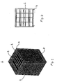
- Suitable filter materials are e.g. tubes spun from plastic strings or filter materials available as Bioblok filter materials.
- the bio filter used in the present invention is a Bioblok filter such as Bioblok 100 having a surface area of 100m 2 /m 3 or a Bioblok 150 having a surface area of 150m 2 /m 3 .
- the air distribution unit may be any unit from which air can be released in the form of small bubbles evenly distributed across the bottom area of the filter and is preferably a diffuser.
- the diffuser delivers an amount of air of between 10 and 100 litres of air per 100 litres of vessel volume per minute.
- a unit according to the invention is preferably provided with a controlling unit for controlling the rate of feeding water to the unit in a manner known per se for distributing the load on the unit evenly over a 24 hour period.
- the invention in a second aspect relates to a plant for treating water, said plant comprising a first vessel for accommodating at least one unit according to the invention and further comprising a second vessel for accumulating particulate material from the water to be treated before said water is fed to the unit, said second vessel being provided an inlet for water to be treated and at least one conduit for feeding water from the second vessel to the inlet connector of the unit, at least one conduit for connected to the outlet for carrying treated water, and at least one connector for supplying power to the compressor and/or pump.
- the inlet of a unit according to the invention is at the same level as a conduit for feeding water to the plant which eliminates the need of a pump for feeding water to the unit and renders a plant of the invention less exposed for stoppage of the function of such a plant.
- a plant according to the invention may comprise from 1 to 12 units according to the invention placed in individual tanks working in series or in parallel or alternatively in a common tank.
- the partially purified waste water exiting from a first unit is passed on to a second unit and so forth giving rise to a further purification.
- a plant according to the invention may be in the form of a long and narrow plant, or a shorter but more compact plant.
- What are decisive for the purification capacity are the cubic capacity of the filter elements and the aeration and the interrelationship of the units as stated above.
- the treated water is then discharged to the recipient via the outlet.
- the plant comprises from 3 to 12 units according to the invention if planned for use in connection with a minor settlement.
- a plant being composed of several separate units in which each unit is separately replaceable enables a construction, in which it is possible in a simple and easy way, to replace individual parts of the plant, or to extend the plant by adding more units, should the need arise, for example, for providing increased capacity in case of an increasing amount of water to be treated. The advantages of this are evident.
- the plant is a small purification plant of the kind provided with a submerged aerated bio filter, such plant preferably having a capacity of treating between 10 and 150 cubic meters of water per day.
- a typical volume of a unit or a section for use in connection with the preferred small plant will be between 3 m 3 and 40 m 3 .
- the interior of the tank of a plant of the invention can, if desired, be divided into a purification portion occupied by units according to the invention and a settling portion by means of a partitioning wall which does not reach all the way to the bottom of the tank.
- a plant according to the invention is preferably provided with a controlling unit for controlling the rate of feeding water to the unit in a manner known per se for distributing the load on the unit evenly over a 24 hour period, e.g. by controlling the output of a feeding pump.
- one or more units according to the invention may be used for providing a plant for purifying a brook, a stream, a feeder or small river. This may especially be of interest in areas in which settlements at the upper course of a brook or the like utilises the same for the discharge of waste water and settlements further downstream uses the same brook or the like as source for drinking water. It its most simple embodiment, a barrage is established and the stream of water led through one or more units according to the invention for purification of the water which units suitably may be incorporated as a part of such a barrage.
- the invention relates to a method for treating water comprising the steps:
- control of the process is constructed and controlled in such manner that the day load on the plant is distributed evenly over all the 24 hours of the day.
- the polluted water By controlling the flow of polluted water through the plant over the time, the polluted water can be passed through the plant evenly distributed over the entire day and hereby provide optimal living conditions for the micro organisms. Optimal bacteria growth conditions result in a more efficient purification, which again gives a reduction of the overcapacity which would else be necessary.
- the water flows though the biodegrading zone at such a rate that settlement occurs in the biodegrading zone.
- a suitable rate can be determined by first determining the averaged settle rate of the particles in the water and then adjusting the flow rate such that the water remains in the zone longer than it takes for an average particle to sink from the top of the zone to the bottom.
- the settlement can settle any desired fraction of the particles by adjusting the flow rate of water to settle rate for the desire fraction.
- the necessary feed to the bacteria also has to be taken into account.
- a unit 1 for water treatment comprises
- Such a unit is provided with at least one connection for a line for feeding compressed air to the air distribution unit, and at least one connection for connecting to an external supply of electrical power.
- FIG 3 shows the unit shown in Figure 1 seen from above.
- a unit or a plant according to the invention may be made in a manner known per se by the skilled in the art after deciding on the materials to be used for a specific embodiment of the invention.
Landscapes
- Life Sciences & Earth Sciences (AREA)
- Biodiversity & Conservation Biology (AREA)
- Microbiology (AREA)
- Hydrology & Water Resources (AREA)
- Engineering & Computer Science (AREA)
- Environmental & Geological Engineering (AREA)
- Water Supply & Treatment (AREA)
- Chemical & Material Sciences (AREA)
- Organic Chemistry (AREA)
- Biological Treatment Of Waste Water (AREA)
- Separation Using Semi-Permeable Membranes (AREA)
Claims (10)
- Einheit umfassend alle zum Durchführen einer Behandlung von Wasser erforderlichen funktionellen Teile, welche Einheit umfassta) ein Gehäuse mit Wänden und einer unteren Ebene, welche eine kastenförmige Kammer definiert, welche wahlweise eine obere Abdeckung aufweist, welche Kammer mit mindestens einem Einlass für zu behandelndes Wasser und mindestens einem Auslass für behandeltes Wasser ausgestattet ist, welcher Auslass in dem unteren Teil der Seitenwände der Kammer vorgesehen ist,b) mindestens einen in der Kammer angeordneten Biofilter, welcher Biofilter eine Höhe aufweist, die kleiner als die Höhe der Seitenwände der Kammer ist, und in der Kammer derart angeordnet ist, dass eine Schlammauffangkammer mit demselben Querschnitt als dem der Kammer in der kastenförmigen Kammer unterhalb des Biofilters gebildet wird,c) mindestens eine in der Kammer zwischen dem Biofilter und dem Boden der Kammer angeordnete Luftverteilungseinheit, welche Luftverteilungseinheit derart positioniert ist, dass die gesamte Luft unterhalb des Biofilters freigegeben wird,d) mindestens eine Verbindung zum Verbinden des Einlasses mit einer Einlassleitung,e) mindestens einen Auslass, welcher Auslass Abmessungen aufweist, die der Größe einer Seite der Schlammauffangkammer entsprechen,f) mindestens eine Verbindung für eine Leitung für die Zufuhr verdichteter Luft in die Luftverteilungseinheit,wobei der mindestens eine Einlass in Form von Löchern (4) vorgesehen ist, welche in einem Abstand von dem oberen Teil der Kammerwände angeordnet sind.
- Einheit nach Anspruch 1, wobei die kastenförmige Kammer von oben gesehen einen quadratischen Querschnitt aufweist.
- Einheit nach Anspruch 1 oder 2, ferner umfassendh) ein Pumpenmittel, dessen Einlass am Boden der Kammer vorgesehen ist.
- Einheit nach einem der Ansprüche 1 bis 3, ferner umfassendi) eine Verdichtungseinheit, welche mit der Leitung für die Zufuhr verdichteter Luft in die Luftverteilungseinheit verbunden ist und wahlweise mit einer Leitung für die Zufuhr verdichteter Luft in Pumpenmittel in der Form von Airliftpumpenmitteln verbunden ist.
- Einheit nach einem der Ansprüche 1 bis 4, wobei das Gehäuse aus einem Kunststoff, wie beispielsweise Polyethylen, Polypropylen oder Polyvinylchlorid, hergestellt ist.
- Einheit nach einem der Ansprüche 1 bis 5, wobei der mindestens eine Biofilter (5) in einer im Vergleich zum Boden vertikalen Position montiert ist.
- Einheit nach einem der Ansprüche 1 bis 6, wobei die Luftverteilungseinheit (6) ein Diffusor ist.
- Anlage zur Behandlung von Wasser, welche Anlage umfasst ein erstes Gefäß zur Aufnahme mindestens einer Einheit nach einem der Ansprüche 1 bis 7 und ferner ein zweites Gefäß zum Akkumulieren partikulären Materials aus dem zu behandelnden Wasser vor der Zufuhr des Wassers in die Einheit umfasst, welches zweite Gefäß mit einem Einlass für zu behandelndes Wasser und mindestens einer Leitung für die Zufuhr von Wasser aus dem zweiten Gefäß in den Einlasskonnektor der Einheit, mindestens einer Leitung, welche zum Tragen von behandeltem Wasser verbunden ist, und mindestens einem Konnektor zur Versorgung des Verdichters und/oder der Pumpe mit Strom ausgestattet ist.
- Anlage zur Behandlung von Wasser, welche Anlage umfasst ein erstes Gefäß zur Aufnahme von mindestens einer Einheit nach einem der Ansprüche 1 bis 7, und wobei sich der Einlass der erfindungsgemäßen Einheit auf der gleichen Ebene wie eine Leitung für die Zufuhr von Wasser in die Anlage befindet.
- Verfahren zur Behandlung von Wasser, welches die folgenden Schritte umfasst:a) Zufuhr des Wassers bei einer Geschwindigkeit, welche die Last über die Einheit über einen Zeitraum von 24 Stunden auf eine Einheit nach einem der Ansprüche 1 bis 7 oder in eine Anlage nach Anspruch 8 oder 9 gleichmäßig verteilt, undb) Versorgung des Verdichters mit Strom für die Zufuhr von Luft in die Luftverteilungseinheit.
Priority Applications (1)
| Application Number | Priority Date | Filing Date | Title |
|---|---|---|---|
| PL08761265T PL2170774T3 (pl) | 2007-06-21 | 2008-06-20 | Jednostka, instalacja i sposób obróbki zanieczyszczonej wody |
Applications Claiming Priority (2)
| Application Number | Priority Date | Filing Date | Title |
|---|---|---|---|
| DKPA200700892 | 2007-06-21 | ||
| PCT/EP2008/057851 WO2008155407A1 (en) | 2007-06-21 | 2008-06-20 | A unit, a plant and a method for treatment of polluted water |
Publications (2)
| Publication Number | Publication Date |
|---|---|
| EP2170774A1 EP2170774A1 (de) | 2010-04-07 |
| EP2170774B1 true EP2170774B1 (de) | 2013-01-09 |
Family
ID=38710482
Family Applications (1)
| Application Number | Title | Priority Date | Filing Date |
|---|---|---|---|
| EP20080761265 Active EP2170774B1 (de) | 2007-06-21 | 2008-06-20 | Einheit, anlage und verfahren zur behandlung von verunreinigtem wasser |
Country Status (8)
| Country | Link |
|---|---|
| US (1) | US8419942B2 (de) |
| EP (1) | EP2170774B1 (de) |
| CN (1) | CN101711228B (de) |
| BR (1) | BRPI0813503B1 (de) |
| DK (2) | DK2170774T3 (de) |
| ES (1) | ES2402449T3 (de) |
| PL (1) | PL2170774T3 (de) |
| WO (1) | WO2008155407A1 (de) |
Family Cites Families (20)
| Publication number | Priority date | Publication date | Assignee | Title |
|---|---|---|---|---|
| JPS6223497A (ja) * | 1985-07-24 | 1987-01-31 | Iwao Ueda | 活性汚泥床による汚水処理装置 |
| JPS6369590A (ja) * | 1986-09-11 | 1988-03-29 | Iseki Kaihatsu Koki:Kk | 浄化装置 |
| US5062958A (en) * | 1988-05-12 | 1991-11-05 | Biotrol, Inc. | Method for water purification |
| US5707513A (en) * | 1992-05-13 | 1998-01-13 | Jowett; E. Craig | Wastewater treatment method and apparatus |
| US5750041A (en) * | 1994-08-15 | 1998-05-12 | Hirane; Ken | Method for backwashing water processing systems |
| DK9600416U4 (da) | 1996-11-26 | 1997-10-24 | Joergen Marcus Ferdinand | Minirenseanlæg |
| CN2338337Y (zh) | 1998-04-15 | 1999-09-15 | 周金生 | 生化除污装置 |
| GB9914888D0 (en) | 1999-06-26 | 1999-08-25 | Mate Stephen F | Sewage plant |
| US6217761B1 (en) * | 1999-07-29 | 2001-04-17 | Delta Environmental Products, Inc. | Wastewater treatment system preventing the build up of solids beneath the clarifier opening |
| DE19945985A1 (de) | 1999-09-24 | 2001-03-29 | Ammermann Gmbh | Mehrkammeranordnung für eine Kläranlage |
| US6942788B1 (en) * | 2003-05-29 | 2005-09-13 | Pentair Pump Group, Inc. | Growth media wastewater treatment reactor |
| US20010045392A1 (en) * | 2000-05-24 | 2001-11-29 | Septitech, Inc. | Wastewater treatment system and method |
| WO2002028784A1 (en) * | 2000-09-29 | 2002-04-11 | Aoki Electric Ind. Co., Ltd. | Waste water treating device |
| AU2002361724B2 (en) | 2001-09-03 | 2008-02-14 | Kwh Pipe (Danmark) As | A method of biologically purifying waste water and a plant preferably a mini purification plant to be used by the method |
| GB2380221B (en) | 2001-09-26 | 2005-12-07 | Hepworth Building Prod | Sewage treatment apparatus for the purification of water |
| US6808622B2 (en) * | 2001-10-12 | 2004-10-26 | Eiwa Country Environment Co., Ltd. | Wastewater purifying apparatus |
| TW593172B (en) * | 2001-10-30 | 2004-06-21 | Ind Tech Res Inst | Floated biological treatment apparatus and process for purifying refractory wastewater or top water |
| ES2190895B2 (es) * | 2002-02-01 | 2004-05-16 | Universida De Santiago De Compostela | Reactor biologico hibrido de membranas para tratamiento de aguas residuales industriales y urbanas. |
| EP1678090B1 (de) | 2003-09-15 | 2014-12-10 | Biokube International A/S | Verfahren und anlage zur abwasserbehandlung |
| CN1807280A (zh) | 2005-12-19 | 2006-07-26 | 东南大学 | 脉冲活性生物过滤装置 |
-
2008
- 2008-06-20 EP EP20080761265 patent/EP2170774B1/de active Active
- 2008-06-20 ES ES08761265T patent/ES2402449T3/es active Active
- 2008-06-20 BR BRPI0813503A patent/BRPI0813503B1/pt not_active IP Right Cessation
- 2008-06-20 WO PCT/EP2008/057851 patent/WO2008155407A1/en not_active Ceased
- 2008-06-20 DK DK08761265T patent/DK2170774T3/da active
- 2008-06-20 CN CN200880021278.XA patent/CN101711228B/zh not_active Expired - Fee Related
- 2008-06-20 US US12/452,228 patent/US8419942B2/en not_active Expired - Fee Related
- 2008-06-20 PL PL08761265T patent/PL2170774T3/pl unknown
-
2009
- 2009-06-24 DK DK200900107U patent/DK200900107U1/da not_active Application Discontinuation
Also Published As
| Publication number | Publication date |
|---|---|
| BRPI0813503B1 (pt) | 2018-09-04 |
| CN101711228B (zh) | 2014-05-07 |
| EP2170774A1 (de) | 2010-04-07 |
| US8419942B2 (en) | 2013-04-16 |
| PL2170774T3 (pl) | 2013-06-28 |
| BRPI0813503A2 (pt) | 2015-01-06 |
| CN101711228A (zh) | 2010-05-19 |
| US20100230349A1 (en) | 2010-09-16 |
| DK200900107U1 (da) | 2009-08-14 |
| ES2402449T3 (es) | 2013-05-03 |
| WO2008155407A1 (en) | 2008-12-24 |
| DK2170774T3 (da) | 2013-04-02 |
Similar Documents
| Publication | Publication Date | Title |
|---|---|---|
| JP5671061B2 (ja) | 廃水処理システム及び方法 | |
| RU2139257C1 (ru) | Установка для биохимической очистки высококонцентрированных сточных вод | |
| US20090065412A1 (en) | Apparatus for waste water treatment | |
| EP2766313B1 (de) | Kleinkläranlage zur biologischen abwasserbehandlung mit verbessertem wirkungsgrad | |
| US4224155A (en) | Sewage treatment apparatus | |
| CN113754210A (zh) | 一种全地埋式钢筋砼结构的小型污水处理系统及处理方法 | |
| US7294254B2 (en) | Wastewater treatment system | |
| CN215975459U (zh) | 一种全地埋式钢筋砼结构的小型污水处理系统 | |
| CN212894377U (zh) | 一种生活污水处理设备 | |
| EP3026022A1 (de) | Mikro-station zur biologischen reinigung | |
| EP2170774B1 (de) | Einheit, anlage und verfahren zur behandlung von verunreinigtem wasser | |
| RU2424986C2 (ru) | Септик | |
| CN218810846U (zh) | 一种灰绿耦合新型一体化设备机 | |
| KR20010074162A (ko) | 침전 및 생물막여과조를 이용한 오수처리장치 및 그 방법 | |
| CN101293724A (zh) | 小型通用污水处理系统 | |
| EP1204607B1 (de) | Verfahren und anordnung zur reinigung von wasser | |
| CN211946680U (zh) | 污水处理用生物降解池 | |
| RU131716U1 (ru) | Канализационная очистная станция закрытого типа | |
| EP1712526B1 (de) | Verfahren und Anordnung zur Abwasserreinigung | |
| CN218811184U (zh) | 污水处理系统 | |
| EP2209747B1 (de) | Anlage zur abwasserbehandlung | |
| WO1998023540A1 (en) | Miniature waste-water treatment system for cleaning of waste-water from one or more households and the like | |
| CN217230504U (zh) | 一种污水处理系统 | |
| RU32775U1 (ru) | Модульная установка для очистки сточных вод | |
| CN109928585A (zh) | 一种一体化水泥商砼罐体污水处理设备 |
Legal Events
| Date | Code | Title | Description |
|---|---|---|---|
| PUAI | Public reference made under article 153(3) epc to a published international application that has entered the european phase |
Free format text: ORIGINAL CODE: 0009012 |
|
| 17P | Request for examination filed |
Effective date: 20100111 |
|
| AK | Designated contracting states |
Kind code of ref document: A1 Designated state(s): AT BE BG CH CY CZ DE DK EE ES FI FR GB GR HR HU IE IS IT LI LT LU LV MC MT NL NO PL PT RO SE SI SK TR |
|
| AX | Request for extension of the european patent |
Extension state: AL BA MK RS |
|
| 17Q | First examination report despatched |
Effective date: 20100817 |
|
| GRAP | Despatch of communication of intention to grant a patent |
Free format text: ORIGINAL CODE: EPIDOSNIGR1 |
|
| GRAS | Grant fee paid |
Free format text: ORIGINAL CODE: EPIDOSNIGR3 |
|
| GRAA | (expected) grant |
Free format text: ORIGINAL CODE: 0009210 |
|
| AK | Designated contracting states |
Kind code of ref document: B1 Designated state(s): AT BE BG CH CY CZ DE DK EE ES FI FR GB GR HR HU IE IS IT LI LT LU LV MC MT NL NO PL PT RO SE SI SK TR |
|
| AX | Request for extension of the european patent |
Extension state: AL BA MK RS |
|
| REG | Reference to a national code |
Ref country code: GB Ref legal event code: FG4D |
|
| REG | Reference to a national code |
Ref country code: CH Ref legal event code: EP Ref country code: AT Ref legal event code: REF Ref document number: 592644 Country of ref document: AT Kind code of ref document: T Effective date: 20130115 |
|
| REG | Reference to a national code |
Ref country code: IE Ref legal event code: FG4D |
|
| REG | Reference to a national code |
Ref country code: DE Ref legal event code: R096 Ref document number: 602008021556 Country of ref document: DE Effective date: 20130307 |
|
| REG | Reference to a national code |
Ref country code: RO Ref legal event code: EPE |
|
| REG | Reference to a national code |
Ref country code: DK Ref legal event code: T3 |
|
| REG | Reference to a national code |
Ref country code: SE Ref legal event code: TRGR |
|
| REG | Reference to a national code |
Ref country code: ES Ref legal event code: FG2A Ref document number: 2402449 Country of ref document: ES Kind code of ref document: T3 Effective date: 20130503 |
|
| REG | Reference to a national code |
Ref country code: NL Ref legal event code: T3 |
|
| REG | Reference to a national code |
Ref country code: NO Ref legal event code: T2 Effective date: 20130109 |
|
| PG25 | Lapsed in a contracting state [announced via postgrant information from national office to epo] |
Ref country code: SI Free format text: LAPSE BECAUSE OF FAILURE TO SUBMIT A TRANSLATION OF THE DESCRIPTION OR TO PAY THE FEE WITHIN THE PRESCRIBED TIME-LIMIT Effective date: 20130109 |
|
| REG | Reference to a national code |
Ref country code: AT Ref legal event code: MK05 Ref document number: 592644 Country of ref document: AT Kind code of ref document: T Effective date: 20130109 |
|
| REG | Reference to a national code |
Ref country code: PL Ref legal event code: T3 |
|
| PG25 | Lapsed in a contracting state [announced via postgrant information from national office to epo] |
Ref country code: BG Free format text: LAPSE BECAUSE OF FAILURE TO SUBMIT A TRANSLATION OF THE DESCRIPTION OR TO PAY THE FEE WITHIN THE PRESCRIBED TIME-LIMIT Effective date: 20130409 Ref country code: BE Free format text: LAPSE BECAUSE OF FAILURE TO SUBMIT A TRANSLATION OF THE DESCRIPTION OR TO PAY THE FEE WITHIN THE PRESCRIBED TIME-LIMIT Effective date: 20130109 Ref country code: AT Free format text: LAPSE BECAUSE OF FAILURE TO SUBMIT A TRANSLATION OF THE DESCRIPTION OR TO PAY THE FEE WITHIN THE PRESCRIBED TIME-LIMIT Effective date: 20130109 Ref country code: IS Free format text: LAPSE BECAUSE OF FAILURE TO SUBMIT A TRANSLATION OF THE DESCRIPTION OR TO PAY THE FEE WITHIN THE PRESCRIBED TIME-LIMIT Effective date: 20130509 |
|
| PG25 | Lapsed in a contracting state [announced via postgrant information from national office to epo] |
Ref country code: GR Free format text: LAPSE BECAUSE OF FAILURE TO SUBMIT A TRANSLATION OF THE DESCRIPTION OR TO PAY THE FEE WITHIN THE PRESCRIBED TIME-LIMIT Effective date: 20130410 Ref country code: PT Free format text: LAPSE BECAUSE OF FAILURE TO SUBMIT A TRANSLATION OF THE DESCRIPTION OR TO PAY THE FEE WITHIN THE PRESCRIBED TIME-LIMIT Effective date: 20130509 Ref country code: LV Free format text: LAPSE BECAUSE OF FAILURE TO SUBMIT A TRANSLATION OF THE DESCRIPTION OR TO PAY THE FEE WITHIN THE PRESCRIBED TIME-LIMIT Effective date: 20130109 Ref country code: FI Free format text: LAPSE BECAUSE OF FAILURE TO SUBMIT A TRANSLATION OF THE DESCRIPTION OR TO PAY THE FEE WITHIN THE PRESCRIBED TIME-LIMIT Effective date: 20130109 |
|
| PG25 | Lapsed in a contracting state [announced via postgrant information from national office to epo] |
Ref country code: HR Free format text: LAPSE BECAUSE OF FAILURE TO SUBMIT A TRANSLATION OF THE DESCRIPTION OR TO PAY THE FEE WITHIN THE PRESCRIBED TIME-LIMIT Effective date: 20130109 |
|
| PG25 | Lapsed in a contracting state [announced via postgrant information from national office to epo] |
Ref country code: SK Free format text: LAPSE BECAUSE OF FAILURE TO SUBMIT A TRANSLATION OF THE DESCRIPTION OR TO PAY THE FEE WITHIN THE PRESCRIBED TIME-LIMIT Effective date: 20130109 Ref country code: EE Free format text: LAPSE BECAUSE OF FAILURE TO SUBMIT A TRANSLATION OF THE DESCRIPTION OR TO PAY THE FEE WITHIN THE PRESCRIBED TIME-LIMIT Effective date: 20130109 |
|
| PLBE | No opposition filed within time limit |
Free format text: ORIGINAL CODE: 0009261 |
|
| STAA | Information on the status of an ep patent application or granted ep patent |
Free format text: STATUS: NO OPPOSITION FILED WITHIN TIME LIMIT |
|
| PG25 | Lapsed in a contracting state [announced via postgrant information from national office to epo] |
Ref country code: CY Free format text: LAPSE BECAUSE OF FAILURE TO SUBMIT A TRANSLATION OF THE DESCRIPTION OR TO PAY THE FEE WITHIN THE PRESCRIBED TIME-LIMIT Effective date: 20130109 |
|
| 26N | No opposition filed |
Effective date: 20131010 |
|
| PG25 | Lapsed in a contracting state [announced via postgrant information from national office to epo] |
Ref country code: MC Free format text: LAPSE BECAUSE OF FAILURE TO SUBMIT A TRANSLATION OF THE DESCRIPTION OR TO PAY THE FEE WITHIN THE PRESCRIBED TIME-LIMIT Effective date: 20130109 |
|
| REG | Reference to a national code |
Ref country code: CH Ref legal event code: PL |
|
| REG | Reference to a national code |
Ref country code: DE Ref legal event code: R097 Ref document number: 602008021556 Country of ref document: DE Effective date: 20131010 |
|
| REG | Reference to a national code |
Ref country code: IE Ref legal event code: MM4A |
|
| PG25 | Lapsed in a contracting state [announced via postgrant information from national office to epo] |
Ref country code: LI Free format text: LAPSE BECAUSE OF NON-PAYMENT OF DUE FEES Effective date: 20130630 Ref country code: CH Free format text: LAPSE BECAUSE OF NON-PAYMENT OF DUE FEES Effective date: 20130630 Ref country code: IE Free format text: LAPSE BECAUSE OF NON-PAYMENT OF DUE FEES Effective date: 20130620 |
|
| PG25 | Lapsed in a contracting state [announced via postgrant information from national office to epo] |
Ref country code: MT Free format text: LAPSE BECAUSE OF FAILURE TO SUBMIT A TRANSLATION OF THE DESCRIPTION OR TO PAY THE FEE WITHIN THE PRESCRIBED TIME-LIMIT Effective date: 20130109 |
|
| PG25 | Lapsed in a contracting state [announced via postgrant information from national office to epo] |
Ref country code: HU Free format text: LAPSE BECAUSE OF FAILURE TO SUBMIT A TRANSLATION OF THE DESCRIPTION OR TO PAY THE FEE WITHIN THE PRESCRIBED TIME-LIMIT; INVALID AB INITIO Effective date: 20080620 Ref country code: LU Free format text: LAPSE BECAUSE OF NON-PAYMENT OF DUE FEES Effective date: 20130620 |
|
| REG | Reference to a national code |
Ref country code: FR Ref legal event code: PLFP Year of fee payment: 9 |
|
| REG | Reference to a national code |
Ref country code: FR Ref legal event code: PLFP Year of fee payment: 10 |
|
| REG | Reference to a national code |
Ref country code: FR Ref legal event code: PLFP Year of fee payment: 11 |
|
| PGFP | Annual fee paid to national office [announced via postgrant information from national office to epo] |
Ref country code: RO Payment date: 20230606 Year of fee payment: 16 Ref country code: NO Payment date: 20230602 Year of fee payment: 16 Ref country code: NL Payment date: 20230602 Year of fee payment: 16 Ref country code: LT Payment date: 20230602 Year of fee payment: 16 Ref country code: IT Payment date: 20230605 Year of fee payment: 16 Ref country code: DE Payment date: 20230602 Year of fee payment: 16 Ref country code: CZ Payment date: 20230608 Year of fee payment: 16 |
|
| PGFP | Annual fee paid to national office [announced via postgrant information from national office to epo] |
Ref country code: TR Payment date: 20230606 Year of fee payment: 16 |
|
| PGFP | Annual fee paid to national office [announced via postgrant information from national office to epo] |
Ref country code: ES Payment date: 20230802 Year of fee payment: 16 |
|
| PGFP | Annual fee paid to national office [announced via postgrant information from national office to epo] |
Ref country code: PL Payment date: 20230616 Year of fee payment: 16 |
|
| REG | Reference to a national code |
Ref country code: DE Ref legal event code: R119 Ref document number: 602008021556 Country of ref document: DE |
|
| REG | Reference to a national code |
Ref country code: LT Ref legal event code: MM4D Effective date: 20240620 |
|
| PG25 | Lapsed in a contracting state [announced via postgrant information from national office to epo] |
Ref country code: CZ Free format text: LAPSE BECAUSE OF NON-PAYMENT OF DUE FEES Effective date: 20240620 |
|
| PG25 | Lapsed in a contracting state [announced via postgrant information from national office to epo] |
Ref country code: RO Free format text: LAPSE BECAUSE OF NON-PAYMENT OF DUE FEES Effective date: 20240620 |
|
| PG25 | Lapsed in a contracting state [announced via postgrant information from national office to epo] |
Ref country code: RO Free format text: LAPSE BECAUSE OF NON-PAYMENT OF DUE FEES Effective date: 20240620 Ref country code: CZ Free format text: LAPSE BECAUSE OF NON-PAYMENT OF DUE FEES Effective date: 20240620 |
|
| REG | Reference to a national code |
Ref country code: NL Ref legal event code: MM Effective date: 20240701 |
|
| PG25 | Lapsed in a contracting state [announced via postgrant information from national office to epo] |
Ref country code: NL Free format text: LAPSE BECAUSE OF NON-PAYMENT OF DUE FEES Effective date: 20240701 |
|
| PG25 | Lapsed in a contracting state [announced via postgrant information from national office to epo] |
Ref country code: NL Free format text: LAPSE BECAUSE OF NON-PAYMENT OF DUE FEES Effective date: 20240701 |
|
| PG25 | Lapsed in a contracting state [announced via postgrant information from national office to epo] |
Ref country code: DE Free format text: LAPSE BECAUSE OF NON-PAYMENT OF DUE FEES Effective date: 20250101 |
|
| PG25 | Lapsed in a contracting state [announced via postgrant information from national office to epo] |
Ref country code: LT Free format text: LAPSE BECAUSE OF NON-PAYMENT OF DUE FEES Effective date: 20240620 |
|
| PG25 | Lapsed in a contracting state [announced via postgrant information from national office to epo] |
Ref country code: NO Free format text: LAPSE BECAUSE OF NON-PAYMENT OF DUE FEES Effective date: 20240630 |
|
| PG25 | Lapsed in a contracting state [announced via postgrant information from national office to epo] |
Ref country code: IT Free format text: LAPSE BECAUSE OF NON-PAYMENT OF DUE FEES Effective date: 20240620 |
|
| PGFP | Annual fee paid to national office [announced via postgrant information from national office to epo] |
Ref country code: GB Payment date: 20250613 Year of fee payment: 18 Ref country code: DK Payment date: 20250612 Year of fee payment: 18 |
|
| PGFP | Annual fee paid to national office [announced via postgrant information from national office to epo] |
Ref country code: FR Payment date: 20250612 Year of fee payment: 18 |
|
| PGFP | Annual fee paid to national office [announced via postgrant information from national office to epo] |
Ref country code: SE Payment date: 20250604 Year of fee payment: 18 |
|
| REG | Reference to a national code |
Ref country code: ES Ref legal event code: FD2A Effective date: 20250801 |
|
| PG25 | Lapsed in a contracting state [announced via postgrant information from national office to epo] |
Ref country code: ES Free format text: LAPSE BECAUSE OF NON-PAYMENT OF DUE FEES Effective date: 20240621 |
|
| PG25 | Lapsed in a contracting state [announced via postgrant information from national office to epo] |
Ref country code: PL Free format text: LAPSE BECAUSE OF NON-PAYMENT OF DUE FEES Effective date: 20240620 |