EP2170622B9 - Security device and method - Google Patents
Security device and method Download PDFInfo
- Publication number
- EP2170622B9 EP2170622B9 EP08762351.8A EP08762351A EP2170622B9 EP 2170622 B9 EP2170622 B9 EP 2170622B9 EP 08762351 A EP08762351 A EP 08762351A EP 2170622 B9 EP2170622 B9 EP 2170622B9
- Authority
- EP
- European Patent Office
- Prior art keywords
- colour
- viewing region
- patterns
- indicia
- pattern
- Prior art date
- Legal status (The legal status is an assumption and is not a legal conclusion. Google has not performed a legal analysis and makes no representation as to the accuracy of the status listed.)
- Active
Links
- 238000000034 method Methods 0.000 title claims description 14
- 239000003086 colorant Substances 0.000 claims description 65
- 239000000758 substrate Substances 0.000 claims description 65
- 239000000976 ink Substances 0.000 claims description 60
- 230000005540 biological transmission Effects 0.000 claims description 30
- 238000007639 printing Methods 0.000 claims description 15
- 239000000463 material Substances 0.000 claims description 8
- 238000004519 manufacturing process Methods 0.000 claims description 5
- 230000000873 masking effect Effects 0.000 claims description 4
- 229920000642 polymer Polymers 0.000 claims description 3
- 239000007787 solid Substances 0.000 claims description 2
- 229920000134 Metallised film Polymers 0.000 description 9
- 239000010408 film Substances 0.000 description 9
- 239000011104 metalized film Substances 0.000 description 9
- 230000000694 effects Effects 0.000 description 7
- 230000003287 optical effect Effects 0.000 description 7
- 238000002310 reflectometry Methods 0.000 description 6
- 230000008901 benefit Effects 0.000 description 5
- 239000004411 aluminium Substances 0.000 description 4
- 229910052782 aluminium Inorganic materials 0.000 description 4
- XAGFODPZIPBFFR-UHFFFAOYSA-N aluminium Chemical compound [Al] XAGFODPZIPBFFR-UHFFFAOYSA-N 0.000 description 4
- 239000002131 composite material Substances 0.000 description 4
- 238000005286 illumination Methods 0.000 description 4
- 238000001459 lithography Methods 0.000 description 4
- 239000002184 metal Substances 0.000 description 4
- 229910052751 metal Inorganic materials 0.000 description 4
- 230000008034 disappearance Effects 0.000 description 3
- 239000004973 liquid crystal related substance Substances 0.000 description 3
- 239000010409 thin film Substances 0.000 description 3
- 239000011248 coating agent Substances 0.000 description 2
- 238000000576 coating method Methods 0.000 description 2
- 238000007646 gravure printing Methods 0.000 description 2
- 125000001475 halogen functional group Chemical group 0.000 description 2
- 239000011159 matrix material Substances 0.000 description 2
- 239000000049 pigment Substances 0.000 description 2
- 230000005855 radiation Effects 0.000 description 2
- 238000007650 screen-printing Methods 0.000 description 2
- 238000013515 script Methods 0.000 description 2
- 241001031135 Aristea ecklonii Species 0.000 description 1
- 229920002799 BoPET Polymers 0.000 description 1
- 238000003491 array Methods 0.000 description 1
- 230000004888 barrier function Effects 0.000 description 1
- 230000000295 complement effect Effects 0.000 description 1
- 238000007796 conventional method Methods 0.000 description 1
- 238000004049 embossing Methods 0.000 description 1
- 230000010354 integration Effects 0.000 description 1
- 238000007644 letterpress printing Methods 0.000 description 1
- 239000007769 metal material Substances 0.000 description 1
- 229910044991 metal oxide Inorganic materials 0.000 description 1
- 150000004706 metal oxides Chemical class 0.000 description 1
- 238000001465 metallisation Methods 0.000 description 1
- 230000000737 periodic effect Effects 0.000 description 1
- 229920003023 plastic Polymers 0.000 description 1
- 229920006254 polymer film Polymers 0.000 description 1
- 229920000307 polymer substrate Polymers 0.000 description 1
- 238000011179 visual inspection Methods 0.000 description 1
Images


Classifications
-
- B—PERFORMING OPERATIONS; TRANSPORTING
- B42—BOOKBINDING; ALBUMS; FILES; SPECIAL PRINTED MATTER
- B42D—BOOKS; BOOK COVERS; LOOSE LEAVES; PRINTED MATTER CHARACTERISED BY IDENTIFICATION OR SECURITY FEATURES; PRINTED MATTER OF SPECIAL FORMAT OR STYLE NOT OTHERWISE PROVIDED FOR; DEVICES FOR USE THEREWITH AND NOT OTHERWISE PROVIDED FOR; MOVABLE-STRIP WRITING OR READING APPARATUS
- B42D25/00—Information-bearing cards or sheet-like structures characterised by identification or security features; Manufacture thereof
- B42D25/30—Identification or security features, e.g. for preventing forgery
- B42D25/337—Guilloche patterns
-
- B—PERFORMING OPERATIONS; TRANSPORTING
- B42—BOOKBINDING; ALBUMS; FILES; SPECIAL PRINTED MATTER
- B42D—BOOKS; BOOK COVERS; LOOSE LEAVES; PRINTED MATTER CHARACTERISED BY IDENTIFICATION OR SECURITY FEATURES; PRINTED MATTER OF SPECIAL FORMAT OR STYLE NOT OTHERWISE PROVIDED FOR; DEVICES FOR USE THEREWITH AND NOT OTHERWISE PROVIDED FOR; MOVABLE-STRIP WRITING OR READING APPARATUS
- B42D25/00—Information-bearing cards or sheet-like structures characterised by identification or security features; Manufacture thereof
- B42D25/40—Manufacture
-
- B—PERFORMING OPERATIONS; TRANSPORTING
- B42—BOOKBINDING; ALBUMS; FILES; SPECIAL PRINTED MATTER
- B42D—BOOKS; BOOK COVERS; LOOSE LEAVES; PRINTED MATTER CHARACTERISED BY IDENTIFICATION OR SECURITY FEATURES; PRINTED MATTER OF SPECIAL FORMAT OR STYLE NOT OTHERWISE PROVIDED FOR; DEVICES FOR USE THEREWITH AND NOT OTHERWISE PROVIDED FOR; MOVABLE-STRIP WRITING OR READING APPARATUS
- B42D15/00—Printed matter of special format or style not otherwise provided for
- B42D15/0053—Forms specially designed for commercial use, e.g. bills, receipts, offer or order sheets, coupons
-
- B—PERFORMING OPERATIONS; TRANSPORTING
- B42—BOOKBINDING; ALBUMS; FILES; SPECIAL PRINTED MATTER
- B42D—BOOKS; BOOK COVERS; LOOSE LEAVES; PRINTED MATTER CHARACTERISED BY IDENTIFICATION OR SECURITY FEATURES; PRINTED MATTER OF SPECIAL FORMAT OR STYLE NOT OTHERWISE PROVIDED FOR; DEVICES FOR USE THEREWITH AND NOT OTHERWISE PROVIDED FOR; MOVABLE-STRIP WRITING OR READING APPARATUS
- B42D25/00—Information-bearing cards or sheet-like structures characterised by identification or security features; Manufacture thereof
- B42D25/30—Identification or security features, e.g. for preventing forgery
- B42D25/324—Reliefs
-
- B—PERFORMING OPERATIONS; TRANSPORTING
- B42—BOOKBINDING; ALBUMS; FILES; SPECIAL PRINTED MATTER
- B42D—BOOKS; BOOK COVERS; LOOSE LEAVES; PRINTED MATTER CHARACTERISED BY IDENTIFICATION OR SECURITY FEATURES; PRINTED MATTER OF SPECIAL FORMAT OR STYLE NOT OTHERWISE PROVIDED FOR; DEVICES FOR USE THEREWITH AND NOT OTHERWISE PROVIDED FOR; MOVABLE-STRIP WRITING OR READING APPARATUS
- B42D25/00—Information-bearing cards or sheet-like structures characterised by identification or security features; Manufacture thereof
- B42D25/30—Identification or security features, e.g. for preventing forgery
- B42D25/355—Security threads
-
- B—PERFORMING OPERATIONS; TRANSPORTING
- B42—BOOKBINDING; ALBUMS; FILES; SPECIAL PRINTED MATTER
- B42D—BOOKS; BOOK COVERS; LOOSE LEAVES; PRINTED MATTER CHARACTERISED BY IDENTIFICATION OR SECURITY FEATURES; PRINTED MATTER OF SPECIAL FORMAT OR STYLE NOT OTHERWISE PROVIDED FOR; DEVICES FOR USE THEREWITH AND NOT OTHERWISE PROVIDED FOR; MOVABLE-STRIP WRITING OR READING APPARATUS
- B42D25/00—Information-bearing cards or sheet-like structures characterised by identification or security features; Manufacture thereof
- B42D25/30—Identification or security features, e.g. for preventing forgery
- B42D25/36—Identification or security features, e.g. for preventing forgery comprising special materials
- B42D25/378—Special inks
- B42D25/387—Special inks absorbing or reflecting ultraviolet light
-
- G—PHYSICS
- G09—EDUCATION; CRYPTOGRAPHY; DISPLAY; ADVERTISING; SEALS
- G09C—CIPHERING OR DECIPHERING APPARATUS FOR CRYPTOGRAPHIC OR OTHER PURPOSES INVOLVING THE NEED FOR SECRECY
- G09C5/00—Ciphering apparatus or methods not provided for in the preceding groups, e.g. involving the concealment or deformation of graphic data such as designs, written or printed messages
-
- B42D2033/04—
-
- B42D2033/06—
-
- B42D2035/24—
-
- B42D2035/36—
-
- B—PERFORMING OPERATIONS; TRANSPORTING
- B42—BOOKBINDING; ALBUMS; FILES; SPECIAL PRINTED MATTER
- B42D—BOOKS; BOOK COVERS; LOOSE LEAVES; PRINTED MATTER CHARACTERISED BY IDENTIFICATION OR SECURITY FEATURES; PRINTED MATTER OF SPECIAL FORMAT OR STYLE NOT OTHERWISE PROVIDED FOR; DEVICES FOR USE THEREWITH AND NOT OTHERWISE PROVIDED FOR; MOVABLE-STRIP WRITING OR READING APPARATUS
- B42D25/00—Information-bearing cards or sheet-like structures characterised by identification or security features; Manufacture thereof
- B42D25/20—Information-bearing cards or sheet-like structures characterised by identification or security features; Manufacture thereof characterised by a particular use or purpose
- B42D25/29—Securities; Bank notes
-
- B—PERFORMING OPERATIONS; TRANSPORTING
- B42—BOOKBINDING; ALBUMS; FILES; SPECIAL PRINTED MATTER
- B42D—BOOKS; BOOK COVERS; LOOSE LEAVES; PRINTED MATTER CHARACTERISED BY IDENTIFICATION OR SECURITY FEATURES; PRINTED MATTER OF SPECIAL FORMAT OR STYLE NOT OTHERWISE PROVIDED FOR; DEVICES FOR USE THEREWITH AND NOT OTHERWISE PROVIDED FOR; MOVABLE-STRIP WRITING OR READING APPARATUS
- B42D25/00—Information-bearing cards or sheet-like structures characterised by identification or security features; Manufacture thereof
- B42D25/30—Identification or security features, e.g. for preventing forgery
- B42D25/351—Translucent or partly translucent parts, e.g. windows
-
- B—PERFORMING OPERATIONS; TRANSPORTING
- B42—BOOKBINDING; ALBUMS; FILES; SPECIAL PRINTED MATTER
- B42D—BOOKS; BOOK COVERS; LOOSE LEAVES; PRINTED MATTER CHARACTERISED BY IDENTIFICATION OR SECURITY FEATURES; PRINTED MATTER OF SPECIAL FORMAT OR STYLE NOT OTHERWISE PROVIDED FOR; DEVICES FOR USE THEREWITH AND NOT OTHERWISE PROVIDED FOR; MOVABLE-STRIP WRITING OR READING APPARATUS
- B42D25/00—Information-bearing cards or sheet-like structures characterised by identification or security features; Manufacture thereof
- B42D25/30—Identification or security features, e.g. for preventing forgery
- B42D25/36—Identification or security features, e.g. for preventing forgery comprising special materials
- B42D25/369—Magnetised or magnetisable materials
-
- B—PERFORMING OPERATIONS; TRANSPORTING
- B42—BOOKBINDING; ALBUMS; FILES; SPECIAL PRINTED MATTER
- B42D—BOOKS; BOOK COVERS; LOOSE LEAVES; PRINTED MATTER CHARACTERISED BY IDENTIFICATION OR SECURITY FEATURES; PRINTED MATTER OF SPECIAL FORMAT OR STYLE NOT OTHERWISE PROVIDED FOR; DEVICES FOR USE THEREWITH AND NOT OTHERWISE PROVIDED FOR; MOVABLE-STRIP WRITING OR READING APPARATUS
- B42D25/00—Information-bearing cards or sheet-like structures characterised by identification or security features; Manufacture thereof
- B42D25/30—Identification or security features, e.g. for preventing forgery
- B42D25/36—Identification or security features, e.g. for preventing forgery comprising special materials
- B42D25/373—Metallic materials
-
- B—PERFORMING OPERATIONS; TRANSPORTING
- B42—BOOKBINDING; ALBUMS; FILES; SPECIAL PRINTED MATTER
- B42D—BOOKS; BOOK COVERS; LOOSE LEAVES; PRINTED MATTER CHARACTERISED BY IDENTIFICATION OR SECURITY FEATURES; PRINTED MATTER OF SPECIAL FORMAT OR STYLE NOT OTHERWISE PROVIDED FOR; DEVICES FOR USE THEREWITH AND NOT OTHERWISE PROVIDED FOR; MOVABLE-STRIP WRITING OR READING APPARATUS
- B42D25/00—Information-bearing cards or sheet-like structures characterised by identification or security features; Manufacture thereof
- B42D25/30—Identification or security features, e.g. for preventing forgery
- B42D25/36—Identification or security features, e.g. for preventing forgery comprising special materials
- B42D25/378—Special inks
- B42D25/382—Special inks absorbing or reflecting infrared light
-
- H—ELECTRICITY
- H04—ELECTRIC COMMUNICATION TECHNIQUE
- H04L—TRANSMISSION OF DIGITAL INFORMATION, e.g. TELEGRAPHIC COMMUNICATION
- H04L2209/00—Additional information or applications relating to cryptographic mechanisms or cryptographic arrangements for secret or secure communication H04L9/00
- H04L2209/56—Financial cryptography, e.g. electronic payment or e-cash
Definitions
- the invention relates to a security device, for example for inclusion in or on a security document such as a document of value, and methods for its manufacture.
- a variety of security devices have been proposed in the past to prevent security documents from being counterfeited or fraudulently produced.
- a particularly useful security device is one which is readily verifiable by a user but which is difficult to produce.
- An example of such a security device is a see-through feature in which complementary images are provided on each side of a document precisely registered relative to one another such that when the document is held up to the light, the image on the back will fit exactly into spaces within the image on the front.
- each image could comprise a series of coloured segments, segments on one side of the sheet fitting within the spaces between the segments on the other. Printing of these images is normally carried out with specialised lithographic presses which allow simultaneous front and back printing during one printing run.
- See-through features have four modes of visual inspection - the image on the first side of the document viewed in reflected light, the image on the other side of the document viewed in reflected light, the composite image viewed by transmitted light as viewed from the first side and with the image on that side predominating, and finally the composite image as viewed on the other side of the sheet with the image on that side predominating.
- transmissive viewing of see-through features the image on the opposite side of the document is seen to be in register in a genuine document.
- DE-A-3208004 describes the use of periodic lineal point patterns on opposite sides of a sheet which, when viewed in transmission, produce a characteristic moiré pattern indicating that the sheet is genuine.
- GB-A-2282563 illustrates the use of apparently random patterns of dots at opposite sides of the sheet which, when viewed in transmission, generate a recognisable pattern.
- EP-A-0628408 relates to the inclusion of a printed layer, laminated between two paper sheets, the print only being visible in transmitted light.
- the image may be registered to an image on one of the outer layers in a cooperative way so as to form a complete image.
- EP-A-0755799 relates to a letterpress printing technique that auto-registers a fluorescent image on one side of a document to a letterpress image on the other side.
- WO-A-97/47478 relates to a security device according to the preamble of claim 1 comprising a substrate having a viewing region which is provided on one side with first indicia and on the other side with second indicia overlying the first indicia.
- the substrate carries an obscuring material aligned with the second indicia so as to prevent the second indicia from being viewed from the one side of the substrate under reflected radiation.
- EP-A-1415828 describes a security feature where patterns are aligned on the front and back surfaces of a document to provide an anti-counterfeiting security device.
- the document is sufficiently transparent to allow see-through of the partial image on the back of the document to be superimposed on the partial image on the front of the document to form a complete image if the patterns are properly aligned. The complete image will not be recognisable if misaligned.
- a security device comprises a substrate having a viewing region; a first pattern of a first colour and a second pattern of a second colour on one side of the viewing region; a third pattern of the first colour and a fourth pattern of the second colour on the other side of the viewing region, wherein the first and second patterns on the one side of the viewing region overlap the fourth and third patterns respectively on the other side of the viewing region whereby
- a method of manufacturing a security device comprises providing a substrate having a viewing region; printing a first pattern of a first colour and a second pattern of a second colour on one side of the viewing region, and a third pattern of the first colour and a fourth pattern of the second colour on the other side of the viewing region, wherein the first and second patterns on the one side of the viewing region overlap the fourth and third patterns respectively on the other side of the viewing region whereby
- the first-to-fourth patterns could all be different in shape and/or layout, preferably the third pattern is in register with and superimposes the second pattern, and the fourth pattern is in register with and superimposes the first pattern. This has the advantage that in transmission the four patterns cause a flat, resultant colour to be visible throughout the viewing region but also the appearance of each side of the viewing region in reflection is similar.
- the first to fourth patterns are in the form of indicia such as an identifying image but more generally may comprise one or more of line patterns, fine filigree line patterns, dot structures, geometric patterns, alphanumeric characters, symbols or other indicia and the like. Each pair of patterns may form indicia independently or cooperate to form indicia.
- the patterns define pseudo-random arrays of pixels in the respective colours. In this case, the existence of a security feature is less obvious when the viewing region is viewed in reflection.
- the single resultant colour seen in transmission may be formed into an image shape such as an indicia, symbol, alphanumeric character or the like.
- the patterns may define continuous blocks of the respective colours or discontinuous regions.
- indicia or alphanumeric characters may include those from non-Roman scripts of which examples include but are not limited to, Chinese, Japanese, Sanskrit and Arabic.
- the indicia will be visible when illuminated by visible light but in a further example the indicia will respond visibly to invisible radiation such as infrared or ultraviolet.
- the patterns are printed onto the substrate. Any of the patterns could be printed using lithography, UV cured lithography, intaglio, letterpress, flexographic printing, gravure printing or screen-printing. Preferably the patterns printed on the front and back of the substrate are printed simultaneously.
- the patterns can be provided using conventional inks such as coloured inks, white inks, black inks, metallic inks, optically variable inks (such as those incorporating thin film optical interference filters or liquid crystal pigment) and the like.
- Thermochromic inks, photochromic inks, magnetic inks, infrared absorbing inks and fluorescing and phosphorescing inks may also be employed.
- the security device of the current invention uses subtractive colour mixing in either a localised area of the viewing region or across the whole viewing region in a novel way to producing striking effects which are memorable to the authenticator.
- traditional see-through features may have more than one colour on either side of the viewing area such that in transmission multiple subtractively mixed colours are observed
- the preferred embodiments of the current invention have the same two colours on either side in substantially perfect register such that only one single colour is observed in transmission.
- the optical effect of going from two colours in reflection to just one colour in transmission is unexpected and therefore striking and memorable to the viewer.
- the striking nature of this optical effect is enhanced further if the switch from two colours in reflection to just one substantially uniform colour in transmission is associated with the disappearance of a recognisable image.
- the requirement that at least in some areas of the viewing region the patterns on either side of the substrate are in substantially perfect register, in order to go from two colours in reflection to one colour in transmission, provides a challenging registrational requirement that is difficult for the counterfeiter to achieve.
- the level of registration produces a complex device which is difficult to copy, the security device itself is easy to verify because the authenticator simply has to check the presence of one single colour either across the whole viewing region or in specific easily identifiable localised areas. This is not the case for a conventional see-through feature with two or more colours on either side of the substrate where any mis-registration can be hidden in the complexity of the multicolour transmissive image.
- the substrate in the viewing region may be the same substrate as that of the secure document it is protecting, for example the security feature of the current invention may be applied by printing the patterns on either side of a traditional banknote paper substrate.
- the substrate In transmission the substrate should be sufficiently transparent to allow the result of the subtractive colour mixing of the colours of the first and second indicia to be observed. It is not necessary that the opacity of the substrate prevents the colour of the third and fourth patterns being observed when the device is viewed in reflection from the side of the first and second patterns as this is achieved through the opacity of the inks used to form the patterns or the use of an additional obscuring layer.
- the substrate may be more transparent in the viewing region than elsewhere.
- the area of greater transparency will be formed typically during the manufacture of the substrate as described in GB-A-2282611 and GB-A-2283026 .
- the substrate comprises a substantially transparent viewing region comprising a polymeric material.
- a substantially transparent viewing region comprising a polymeric material.
- Techniques are known in the art for forming transparent regions in both paper and polymeric substrates.
- WO-A-8300659 describes a polymer banknote formed from a transparent substrate comprising an opacifying coating on both sides of the substrate. The opacifying coating is omitted in localised regions on both sides of the substrate to form a transparent region.
- WO-A-0039391 describes a method of making a transparent polymeric region in a paper substrate.
- the patterns can be applied to the viewing region either before or after the material forming the viewing region is incorporated into the substrate.
- the patterns are applied after the material forming the viewing region is incorporated into the substrate and using the same conventional printing processes that are used to print the substrate. This also enables the patterns to be exactly registered with other indicia on the substrate.
- security documents with which the present invention can be used include banknotes, fiscal stamps, cheques, postal stamps, certificates of authenticity, articles used for brand protection, bonds, payment vouchers, and the like.
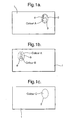
- the security document shown in Figure 1 comprises a substrate 1 which may be paper or polymer, in this case paper.
- the substrate defines front and rear sides and has a substantially transparent viewing region 2.
- the substantially transparent viewing region 2 may have been formed using any of the conventional methods cited above.
- first and second patterns 3,4 are printed in colours A and B respectively to define first indicia.
- colour A is magenta (for example standard lithographic printing ink "Pantone® Process Magenta U” can be used)
- colour B is cyan (for example standard lithographic printing ink "Pantone® Process Cyan U” can be used).
- the patterns are in the form of a company logo 3 with colour A (magenta) forming the portrait on the front side of the viewing region and colour B (cyan) forming the background area 4.
- third and fourth patterns 5,6 are printed using the same colours A and B to form second indicia.
- the second indicia is the same as the first indicia apart from the fact that the colours are now reversed such that colour B (cyan) now forms the portrait 6 ("fourth pattern") and colour A (magenta) forms the background region 5 ("third pattern").
- the first and second indicia are applied in substantially perfect register such that the first pattern 3 is directly superimposed on the fourth pattern 6 while the second pattern 4 is directly superimposed on the third pattern 5.
- the first and second indicia are printed simultaneously on the front and rear side of the viewing region 2 using lithographic printing.
- the optical properties of the inks used to form the first and second indicia are selected such that when viewing the device in reflection from the front of the substrate the colours of the first indicia substantially conceals the colours of the second indicia such that a magenta portrait is observed on a cyan background ( Figure 1a ). Likewise when viewing the device in reflection from the rear of the substrate the colours of the second indicia substantially conceals the colours of the first indicia such that a cyan portrait is observed on a magenta background ( Figure 1 b) .
- the coloured printed inks allow sufficient light transfer that a combined colour is observed as a result of the subtractive colour mixing of colours A and B. In this example both the portrait and the background will appear blue, resulting from the combination of cyan and magenta, and in this manner the identifying image disappears when viewing in transmission and is replaced with a perceived single colour region. ( Figure 1 c) .
- the registration requirements of the current invention also has a further tolerance constraint beyond conventional see-through devices, since generally it not only requires substantially perfect front to back registration, but also substantially perfect interlocking registration between the two colours on the same side of the device. Any misregistration with regard to the colours on the same side of the device again would result in localised halos or outline of the misregistered indicia which are easily identified against the uniform background generated by the disappearing image.
- the optical properties of the inks should be chosen such that when viewed in reflection the colour of the top layer of ink is the dominant colour and there is negligible effect from the colour of the underlying ink on the opposite side of the device. Furthermore the colour of the inks to form colours A and B should be chosen to provide relatively high contrast between the regions A and B when viewed in reflection.
- the difference in the contrast in the two colours in reflected light can be enhanced by increasing the reflectivity of one of the colours.
- This can be achieved by incorporating a reflective component such as a metallic flake into one of the inks.
- a reflective component such as a metallic flake
- the reflectivity of one of the inks could be increased by incorporating metallic flakes into the ink.
- one of the inks could be a standard coloured lithographic ink and one could be a metallic lithographic ink.
- both of the printed inks could be metallic inks.
- the use of high reflectivity inks, such as metallic inks helps to conceal the presence of the ink on the other side of the substrate when the device is viewed in reflection.
- an obscuring layer is used between the two sets of indicia such that in reflection the colour on the side of the device being viewed is dominant, and the effect of the colour on the opposite side of the substrate is negligible.
- the use of an obscuring layer is known for conventional see- through features and is described in WO-A-9747478 .
- the obscuring layer prevents the colour of the second indicia being observed when the device is viewed in reflection from the side of the first indicia. In transmission the obscuring layer is sufficiently transparent to allow the result of the subtractive colour mixing of the colours of the first and second indicia to be observed.
- the obscuring material could be used for the obscuring material but a good example for the present invention is the use of a vapour deposited metallic layer.
- the transparent substrate within the viewing region could be coated with a metallic material which is then partially demetallised to enable the feature to be viewed in transmitted light.
- the obscuring layer is in the form of a screen.
- the metallised pattern could be an array of dots or lines with sufficient coverage to maintain the reflectivity but sufficiently transparent to enable colour mixing of the first and second indicia to be viewable in transmitted light.
- Non-linear screens are also envisaged.
- the screen could comprise a circular or sinusoidal array of dots or lines...
- the screen can be regular or stochastic. Indeed, the term "screen” should be construed broadly to encompass many different shapes of screen elements.
- the coverage of the screen pattern is in the range 20-80%, and more preferably in the range 40-70% and even more preferably in the range 50-70%.
- the width of the lines or the diameter of the dots forming the screen are preferably in the range 50-250 ⁇ m and the spaces between the dots or lines are also in the range 50-250 ⁇ m with values of each set chosen to achieve the desired screen coverage.
- the metallised pattern could be an array of dots or lines with sufficient coverage to maintain the reflectivity but sufficiently transparent to enable colour mixing of the first and second indicia to be viewable in transmitted light.
- This is particularly appropriate with a polymeric substrate.
- the substrate could be coated with a very thin film of aluminium, metal oxide or other reflective layer such that again it exhibits both high reflectivity and sufficient transparency.
- the obscuring layer could be formed by a printed metallic ink.
- the obscuring layer can comprise a masking coat.
- a masking coat would be Coates 3188XSN or Coates Heliovyl White S90 353.
- a typical coat weight is suggested to be in the region of 1-3GSM.
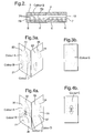
- Figure 2 illustrates the use of an obscuring layer.
- the viewing region comprises a transparent substrate 10.
- the first and second patterns 3,4 defining the first indicia are printed in colours A and B as in the example illustrated in Figure 1 .
- the rear side of the substrate 10 comprises a patterned metallised film 7 which in this example is an array of closely spaced fine lines 7A separated by spaces 7B.
- the metallised film will typically be a metallised PET film for example MELINEX S film from DuPont, this will then be demetallised to form a screen so in the spaces there is just clear demetallised polymer film.
- the second indicia 5,6 is printed onto the patterned metallised film using the same colours A and B and such that every colour A element of the first indicia is perfectly registered to every colour B element of the second indicia and every colour B element of the first indicia is perfectly registered to every colour A element of the second indicia.
- the width of the lines 7A and the spacing 7B between the lines of the patterned metallised film is preferably non-resolvable such that the substrate appears metallic in reflective light but appears uniformly transparent in transmissive light to enable the colour mixing of the A and B elements to be observed.
- the presence of the reflective obscuring layer 10 increases the brightness of the image in reflected light and ensures there is a strong contrast between the two colours A and B in reflected light by minimising the influence of the underlying colour on the opposite side of the substrate.
- a third colour D which has the same appearance in transmission as combined colour C, which is a result of the subtractive colour mixing of colours A and B, is printed on the front and/or rear side of the viewing region.
- This provides the device with a further level of complexity and increases the challenge to any potential counterfeiter in the form of further registrational requirements and also the requirement to match the appearance of the printed colour D to the colour C produced from the subtractive colour mixing of colours A and B.
- the first indicia is defined by first and second patterns 20,21 printed in colours A and B and a further pattern 22 printed in colour D to form a pictorial design.
- colour A is magenta
- colour B is cyan
- colour D is blue.
- the second indicia is defined by third and fourth patterns 23,24 printed using colours A and B.
- the second indicia is the same as the first indicia apart from the fact that the region 25 in alignment with pattern 22 occupied by colour D in the first indicia is now colourless.
- the first and second indicia are applied in substantially perfect register such that the first indicia are directly superimposed on the second indicia.
- Figure 4 illustrates a further example where the first and second indicia, which define the image that will ultimately disappear in transmitted light, are integrated with a further image that remains visible in both transmission and reflection.
- the first indicia and the second indicia each comprise regions printed in colours A, B and D to form a multicolour pictorial design.
- the first indicia is applied to the front side of the document as first and second patterns 30,31 in colours A and B and a pattern in colour D 32 and the second indicia is applied to the rear side of the document as third and fourth patterns 33,34 in colours A and B and a pattern in colour D 35.
- the regions printed in colours A and B on the front and rear sides of the viewing region are superimposed with their opposite colours.
- the region printed in colour D is split between the front 32 and rear 35 sides with corresponding colourless regions 36,37 on the other side but when combined the respective colour D elements 32,35,36,37 fit together in the same manner as a conventional see-through such that the image is the same on either side of the viewing region.
- a further image, in this case the number "200" is then printed on the front side of the viewing region in register with the mulitcolour pictorial design formed by the first and second indicia.
- the authenticator On viewing the device, illustrated in Figure 4 , in reflection ( Figure 4a ) the authenticator will see a similar three colour image on either side of the viewing region surrounding the printed number "200".
- the multi-coloured identifying image disappears but the image of the number "200" remains visible.
- the integration of the disappearing image with a permanent image not only increases the aesthetics of the device but also makes it more memorable to the general public.
- the disappearing image is used to draw the attention of the viewer to the permanent image that can contain important information such as the value of the protected document.
- This embodiment of the invention is applicable to both paper and polymer substrates and the permanent image can be applied by printing as well as metallization or demetallisation techniques. Suitable printing techniques include lithography, UV cured lithography, intaglio, letterpress, flexographic printing, gravure printing or screen-printing.
- the permanent image must be sufficiently opaque to appear as a silhouette in transmitted light.
- the permanent image can take any form such as patterns, symbols and alphanumeric characters and combinations thereof.
- the indicia can be defined by patterns comprising solid or discontinuous regions which may include for example line patterns, fine filigree line patterns, dot structures and geometric patterns. Possible characters include those from non-Roman scripts of which examples include but are not limited to, Chinese, Japanese, Sanskrit and Arabic.
- the permanent image may be single-coloured or multi-coloured.
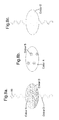
- FIG 5 illustrates an example where the security device of the current invention is incorporated into a transparent region of a paper substrate 40.
- a transparent elongate polymeric film 41 is incorporated into a paper substrate 40 as described in WO-A-0039391 .
- One side of the transparent elongate polymeric film 41 is wholly exposed at one surface of a paper substrate in which it is partially embedded ( Figure 5a ), and partially exposed in one aperture 42 at the other surface of the substrate ( Figure 5b ).
- the apertures formed in the paper can be used as the viewing region in the current invention.
- first and second indicia are lithographically printed onto the front ( Figure 5a ) and rear side ( Figure 5b ) of the viewing region respectively.
- the first indicia are provided as first and second patterns 43,44 (background and stars) in colours A (yellow) and B (blue) respectively while the second indicia are printed as third and fourth patterns 45,46 (stars and background) in colours A and B respectively.
- every colour A element of the first indicia is perfectly registered to every colour B element of the second indicia and every colour B element of the first indicia is perfectly registered to every colour A element of the second indicia.
- the indicia form a pictorial design which is an array of stars on a coloured background.
- the transparent elongate polymeric film 41 comprises a metallised image in the form of the number "500" repeating along the length of the film. It is known that metallised films can be produced such that no metal is present in controlled and clearly defined areas. Such partly metallised film can be made in a number of ways. One way is to selectively demetallise regions using a resist and etch technique such as is described in US4652015 . Other techniques are known for achieving similar effects; for example it is possible to vacuum deposit aluminium through a mask or aluminium can be selectively removed from a composite strip of a plastic support and aluminium using an excimer laser.
- the metallised film 41 in Figure 5 used to produce the permanent image may also act as an obscuring layer.
- most of the metallised film will comprise an array of closely spaced fine lines as described with reference to Figure 2 , but in the localised regions of the permanent image the metal coverage will be complete, i.e. substantially 100%, and the image will be revealed in transmitted light.
- the metallised film will be screened, for example comprising an array of closely spaced fine lines or dots, and in localised areas will comprise a permanent image formed by the complete removal of the metal.
- the areas of complete metal removal will not interfere with the visibility of the first and second patterns in transmitted light.
- all of the viewing region switches from a multi-coloured image when viewed in reflection to a perceived single coloured uniform region when viewed in transmission resulting in the disappearance of the multi-coloured image.
- only localised areas of the viewing region switches from multi-coloured to one colour, providing the disappearing effect, and other regions remain multi-coloured. This enables the switching regions to be used to reveal a perceived single colour image in transmitted light against a multi-coloured background.
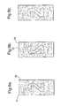
- Figure 6 shows an example of a device where the viewing regions comprise two areas, one which switches on viewing in transmitted light and one which doesn't.
- the viewing region is provided on one side with first and second patterns 50,51 defined by colour elements A (blue) and B (yellow) respectively forming one set of indicia and on the other side with third and fourth patterns 52,53 defined by colour elements A (yellow) and B (blue) forming a second different set of indicia.
- the indicia comprise an apparently random array of pixels where each pixel is either coloured yellow or blue.
- the registration of the first and second indicia is such that in area 1 of the viewing region the two colours are present on both sides of the viewing region and the blue pixels in the first set of indicia overlaps with the yellow pixels in the second set of indicia and likewise the yellow pixels in the first set of indicia overlaps with the blue pixels in the second set of indicia.
- the registration is such that blue pixels in the first set of indicia overlaps with the blue pixels in the second set of indicia and likewise the yellow in the first set of indicia overlaps with the yellow pixels in the second set of indicia.
- the optical properties such as opacity of the ink used to form the first and second indicia are again selected such that when viewing the device in reflection from the front of the device the colours of the first indicia substantially conceals the colours of the second indicia.
- an obscuring layer could be used between the first and second indicia.
- area 1 switches from an apparently random array of yellow and blue pixels to a uniform green region resulting from the subtractive colour mixing of the perfectly registered blue and yellow pixels.
- area 2 appears the same in reflection and transmission and still comprises an apparently random area of blue and yellow pixels resulting from the fact that in area 2 every blue and yellow pixel on the front side is in perfect register with an equivalently coloured pixel on the reverse side.
- area 1 defines the numeral "2" which is revealed on viewing in transmitted light due to it switching from a random two colour region which merges in with the background to a perceived single colour region which contrasts with the background.
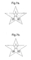
- Figure 7 schematically illustrates an example of a viewing region of the current invention comprising multiple localised areas that switch from being multi-coloured to a single colour, providing the disappearing effect, against a background that remains multi-coloured.
- the viewing region itself defines an image in the form of a star and the first and second indicia comprise an apparently random array of pixels where each pixel is either coloured yellow or blue.
- areas 1 a, 1b and 1 c appears indistinguishable from area 2 and the authenticator observes a star filled with an apparently random array of yellow and blue pixels.
- areas 1 a, 1 b and 1 c switch from an apparently random array of yellow and blue pixels to a uniform green colour resulting from the subtractive colour mixing of the perfectly registered blue and yellow pixels.
- Area 1 a is in the form of a small star, and areas 1 b and 1 c are in the form of a numeral "50".
- area 2 appears the same in reflected and transmitted light and still comprises an apparently random area of blue and yellow pixels resulting from the fact that in area 2 every blue and yellow pixel on the front side is in perfect register with an equivalently coloured pixel on the reverse side.
- the disappearance of the pixels in areas 1 a, 1 b and 1 c on viewing in transmission is used to reveal multiple images thereby creating a security device which is striking and memorable to the authenticator.
- the individual image elements forming the indicia are pixels but the invention is not limited to pixels and any array of image elements can be employed typical examples include dots, polygons, lines, and any other geometric shape.
- a third colour D can be introduced into the examples illustrated in Figures 6 and 7 .
- the indicia would then comprise an apparently random array of pixels where each pixel is either coloured yellow, blue or green, where in transmission the appearance of the green pixel would match the green colour resulting from the subtractive colour mixing of the yellow and blue pixels.
- the apparently random pattern used in the examples shown in Figures 6 and 7 can be generated in the form of a 2d matrix barcode such as a QR Code or Data Matrix code.
- a 2d matrix barcode such as a QR Code or Data Matrix code.
- Such 2D barcodes can be read by specialised readers or alternatively easily read by the general public using cameras within mobile phones or webcams. This would provide the security feature with an additional machine-readable component and further enhance its counterfeit resistance.
- the indicia and/or resultant images of the current invention are associated with further indicia on either side of the secure document either within or adjacent to the viewing region.
- the further indicia can be provided using conventional inks such as coloured inks, white inks, black inks, metallic inks, optically variable inks (such as those incorporating thin film optical interference filters or liquid crystal pigment) and the like.
- Thermochromic inks may also be employed.
- the further indicia can be provided by metallised/demetallised designs, holographic designs, liquid crystal films or security embossings of transparent films.
- Figure 8 illustrates an example where the first and second indicia inside the viewing region are registered with a third indicia outside the viewing region.
- first indicia first and second patterns
- colour A is magenta
- colour B is cyan
- colour D is blue.
- second indicia third and fourth patterns
- the second indicia is the same as the first indicia apart from the fact that the region occupied by colour D in the first indicia is now colourless.
- the first and second indicia are applied in substantially perfect register such that the first indicia are directly superimposed on the second indicia.
- Further indicia 60 are printed on the front of the document and these are registered to the first and second indicia such that the pictorial design continues uninterrupted from the viewing region onto the document.
- the further indicia 60 may be in the same colours or different colours to the first and second indicia.
- the substrate for the viewing region of the security device could comprise regions of different transparency.
- the secure document comprised a transparent polymeric aperture 70 within a paper document 71
- the viewing region 72 could be formed over both the paper and the polymeric regions, as illustrated in Figure 9 .
- the first ( Figure 9a ) and second ( Figure 9b ) indicia are both printed in colours A (yellow) and B (blue) as before such that every colour A element of the first indicia is perfectly registered to every colour B element of the second indicia and every colour B element of the first indicia is perfectly registered to every colour A element of the second indicia.
- the indicia form a pictorial design.
- the security device of the current invention can be combined with a conventional see-though feature commonly observed on banknotes.
- the secure document comprises a transparent polymeric viewing region 80 within a paper document 81, as illustrated in Figure 10 .
- the first ( Figure 10a ) and second ( Figure 10b ) indicia, positioned inside the transparent viewing region, are both printed in colours A (yellow) and B (blue) as before such that every colour A element of the first indicia is perfectly registered to every colour B element of the second indicia and every colour B element of the first indicia is perfectly registered to every colour A element of the second indicia.
- the indicia form a pictorial design.
- the pictorial design is registered to a conventional see-through which adjoins the viewing region.
- the conventional see-through comprises regions 82 on the same side of the substrate as the first indicia and regions 83 on the same side of the substrate as the second indicia. Regions 82 and 83 are in the same colour as the second indicia, colour B (Blue). On viewing the device in transmitted light subtractive colour mixing of colours A and B results in the viewing region switching to a single colour C which in this case is green.
- the regions of the conventional see-through are precisely registered relative to one another such that when the document is held up to the light, the regions 83 on the back fit exactly into spaces within the regions 82 on the front forming an image which then combines with the viewing region 80 to form a complete image 84.
- the inks used to form the first and/or second set of indicia may also contain functional components that react to an external stimulus.
- Components of this type include, but are not limited to, fluorescent, phosphorescent, infrared absorbing, thermochromic, photochromic, magnetic, electrochromic, conductive and piezochromic.
- a fluorescent component can be added to the inks used to form the first and/or second set of indicia.
- a fluorescent component is added to the ink of colour A such that when colour A is viewed under visible light illumination it sill appears cyan but when viewed under UV illumination it appears red.
- a fluorescent component is added to the ink of colour B such that when colour B is viewed under visible light illumination it sill appears magenta but when viewed under UV illumination it appears blue.
- the indicia will disappear and be replaced with a single colour region, in this example magenta which is different from the blue colour observed in transmitted visible light.
- a fluorescent component can be added to the inks used to form the first and/or second set of indicia such that when viewed in reflected visible light colour A is different from colour B (e.g. cyan and magenta) but when viewed in reflected UV light colour A is the same as colour B.
- colour B e.g. cyan and magenta
- colour A when viewed in reflected UV light colour A is the same as colour B.
- the inks used to form the first and/or second set of indicia may be selected such that when viewed in reflected visible light colour A is the same as colour B but when viewed in reflected UV light colour A is the different to colour B.
- the security feature of the current invention can only be observed when viewing in reflected and transmitted UV light and its presence is not apparent in visible light.
- Suitable inks which exhibit substantially the same visible appearance under first viewing conditions and different visible appearances under second viewing conditions are referenced in WO-A-2004050376 .
Landscapes
- Engineering & Computer Science (AREA)
- Business, Economics & Management (AREA)
- Accounting & Taxation (AREA)
- Finance (AREA)
- Physics & Mathematics (AREA)
- General Physics & Mathematics (AREA)
- Theoretical Computer Science (AREA)
- Manufacturing & Machinery (AREA)
- Printing Methods (AREA)
- Credit Cards Or The Like (AREA)
- Inspection Of Paper Currency And Valuable Securities (AREA)
- Non-Metallic Protective Coatings For Printed Circuits (AREA)
Description
- The invention relates to a security device, for example for inclusion in or on a security document such as a document of value, and methods for its manufacture.
- A variety of security devices have been proposed in the past to prevent security documents from being counterfeited or fraudulently produced. A particularly useful security device is one which is readily verifiable by a user but which is difficult to produce. An example of such a security device is a see-through feature in which complementary images are provided on each side of a document precisely registered relative to one another such that when the document is held up to the light, the image on the back will fit exactly into spaces within the image on the front. For example, each image could comprise a series of coloured segments, segments on one side of the sheet fitting within the spaces between the segments on the other. Printing of these images is normally carried out with specialised lithographic presses which allow simultaneous front and back printing during one printing run. See-through features have four modes of visual inspection - the image on the first side of the document viewed in reflected light, the image on the other side of the document viewed in reflected light, the composite image viewed by transmitted light as viewed from the first side and with the image on that side predominating, and finally the composite image as viewed on the other side of the sheet with the image on that side predominating. On transmissive viewing of see-through features the image on the opposite side of the document is seen to be in register in a genuine document.
- An example of see-through features used with banknotes and the like is described in
EP-A-0388090 in which the feature is provided in a region of the sheet which has a substantially uniform transparency which is more transparent than a majority of the remainder of the sheet in the absence of applied ink. -
DE-A-3208004 describes the use of periodic lineal point patterns on opposite sides of a sheet which, when viewed in transmission, produce a characteristic moiré pattern indicating that the sheet is genuine. -
GB-A-2282563 -
EP-A-0628408 relates to the inclusion of a printed layer, laminated between two paper sheets, the print only being visible in transmitted light. The image may be registered to an image on one of the outer layers in a cooperative way so as to form a complete image. -
EP-A-0755799 relates to a letterpress printing technique that auto-registers a fluorescent image on one side of a document to a letterpress image on the other side. -
WO-A-97/47478 claim 1 comprising a substrate having a viewing region which is provided on one side with first indicia and on the other side with second indicia overlying the first indicia. The substrate carries an obscuring material aligned with the second indicia so as to prevent the second indicia from being viewed from the one side of the substrate under reflected radiation. -
EP-A-1415828 describes a security feature where patterns are aligned on the front and back surfaces of a document to provide an anti-counterfeiting security device. The document is sufficiently transparent to allow see-through of the partial image on the back of the document to be superimposed on the partial image on the front of the document to form a complete image if the patterns are properly aligned. The complete image will not be recognisable if misaligned. - Although the "see-through" features of the prior art perform satisfactorily there is always a requirement to provide improved see-through features which exhibit novel surprising effects to prevent counterfeiting.
- In accordance with one aspect of the present invention, a security device comprises a substrate having a viewing region; a first pattern of a first colour and a second pattern of a second colour on one side of the viewing region; a third pattern of the first colour and a fourth pattern of the second colour on the other side of the viewing region, wherein the first and second patterns on the one side of the viewing region overlap the fourth and third patterns respectively on the other side of the viewing region whereby
- a) when each side of the viewing region is viewed in reflected light, the patterns on that side can be distinguished by at least their colours, and
- b) when the viewing region is viewed in transmitted light, the viewing region is sufficiently transparent that subtractive colour mixing between the overlapped different colours results in a perceived single resultant colour being visible.
- In accordance with another aspect of the present invention, a method of manufacturing a security device comprises providing a substrate having a viewing region; printing a first pattern of a first colour and a second pattern of a second colour on one side of the viewing region, and a third pattern of the first colour and a fourth pattern of the second colour on the other side of the viewing region, wherein the first and second patterns on the one side of the viewing region overlap the fourth and third patterns respectively on the other side of the viewing region whereby
- a) when each side of the viewing region is viewed in reflected light, the patterns on that side can be distinguished by at least their colours, and
- b) when the viewing region is viewed in transmitted light, from either side of the substrate, the viewing region is sufficiently transparent that subtractive colour mixing between the overlapped different colours results in a perceived single resultant colour being visible.
- We have developed a new type of see-through feature which exploits subtractive colour mixing. When the device is viewed in reflection on either side, the contrast between the two colours enables the two patterns on that side to be distinguished. However, when the device is viewed in transmission, the overlapping, different colours subtract respective wavelengths or wavelength bands from the incident light such that the resultant light transmitted through both sets of overlapping patterns has substantially the same colour and thus it is no longer possible to distinguish between the individual patterns. The advantage of this security device is that it is easy to inspect but difficult to fabricate.
- Although the first-to-fourth patterns could all be different in shape and/or layout, preferably the third pattern is in register with and superimposes the second pattern, and the fourth pattern is in register with and superimposes the first pattern. This has the advantage that in transmission the four patterns cause a flat, resultant colour to be visible throughout the viewing region but also the appearance of each side of the viewing region in reflection is similar.
- In preferred examples, the first to fourth patterns are in the form of indicia such as an identifying image but more generally may comprise one or more of line patterns, fine filigree line patterns, dot structures, geometric patterns, alphanumeric characters, symbols or other indicia and the like. Each pair of patterns may form indicia independently or cooperate to form indicia.
- In other examples, the patterns define pseudo-random arrays of pixels in the respective colours. In this case, the existence of a security feature is less obvious when the viewing region is viewed in reflection.
- In either case, the single resultant colour seen in transmission may be formed into an image shape such as an indicia, symbol, alphanumeric character or the like.
- The patterns may define continuous blocks of the respective colours or discontinuous regions.
- Where indicia or alphanumeric characters are defined, these may include those from non-Roman scripts of which examples include but are not limited to, Chinese, Japanese, Sanskrit and Arabic. Typically the indicia will be visible when illuminated by visible light but in a further example the indicia will respond visibly to invisible radiation such as infrared or ultraviolet.
- Typically, the patterns are printed onto the substrate. Any of the patterns could be printed using lithography, UV cured lithography, intaglio, letterpress, flexographic printing, gravure printing or screen-printing. Preferably the patterns printed on the front and back of the substrate are printed simultaneously. The patterns can be provided using conventional inks such as coloured inks, white inks, black inks, metallic inks, optically variable inks (such as those incorporating thin film optical interference filters or liquid crystal pigment) and the like. Thermochromic inks, photochromic inks, magnetic inks, infrared absorbing inks and fluorescing and phosphorescing inks may also be employed.
- In summary, the security device of the current invention uses subtractive colour mixing in either a localised area of the viewing region or across the whole viewing region in a novel way to producing striking effects which are memorable to the authenticator. Whereas traditional see-through features may have more than one colour on either side of the viewing area such that in transmission multiple subtractively mixed colours are observed, the preferred embodiments of the current invention have the same two colours on either side in substantially perfect register such that only one single colour is observed in transmission. The optical effect of going from two colours in reflection to just one colour in transmission is unexpected and therefore striking and memorable to the viewer. The striking nature of this optical effect is enhanced further if the switch from two colours in reflection to just one substantially uniform colour in transmission is associated with the disappearance of a recognisable image.
- Furthermore the requirement that at least in some areas of the viewing region the patterns on either side of the substrate are in substantially perfect register, in order to go from two colours in reflection to one colour in transmission, provides a challenging registrational requirement that is difficult for the counterfeiter to achieve. Although the level of registration produces a complex device which is difficult to copy, the security device itself is easy to verify because the authenticator simply has to check the presence of one single colour either across the whole viewing region or in specific easily identifiable localised areas. This is not the case for a conventional see-through feature with two or more colours on either side of the substrate where any mis-registration can be hidden in the complexity of the multicolour transmissive image.
- The substrate in the viewing region may be the same substrate as that of the secure document it is protecting, for example the security feature of the current invention may be applied by printing the patterns on either side of a traditional banknote paper substrate. In transmission the substrate should be sufficiently transparent to allow the result of the subtractive colour mixing of the colours of the first and second indicia to be observed. It is not necessary that the opacity of the substrate prevents the colour of the third and fourth patterns being observed when the device is viewed in reflection from the side of the first and second patterns as this is achieved through the opacity of the inks used to form the patterns or the use of an additional obscuring layer.
- The substrate may be more transparent in the viewing region than elsewhere. In the case of a solely paper substrate the area of greater transparency will be formed typically during the manufacture of the substrate as described in
GB-A-2282611 GB-A-2283026 - Alternatively the substrate comprises a substantially transparent viewing region comprising a polymeric material. Techniques are known in the art for forming transparent regions in both paper and polymeric substrates. For example,
WO-A-8300659 -
WO-A-0039391 - Other methods for forming transparent regions in paper substrates are described in
EP-A-723501 EP-A-724519 WO-A-03054297 - In the case where the viewing region is formed from a different material than the document substrate, the patterns can be applied to the viewing region either before or after the material forming the viewing region is incorporated into the substrate. Preferably, the patterns are applied after the material forming the viewing region is incorporated into the substrate and using the same conventional printing processes that are used to print the substrate. This also enables the patterns to be exactly registered with other indicia on the substrate.
- Examples of security documents with which the present invention can be used include banknotes, fiscal stamps, cheques, postal stamps, certificates of authenticity, articles used for brand protection, bonds, payment vouchers, and the like.
- Some examples of security devices located on or in security documents according to the invention will now be described with reference to the accompanying drawings, in which:-
-
Figures 1a-1c are schematic, plan views of a security document for carrying a first example of a security device according to the invention when viewed in reflection from opposite sides and in transmission respectively; -
Figure 2 is a cross-section through a second example of a security device incorporating an obscuring layer; -
Figures 3a and 3b illustrate a third example of a security device according to the invention when viewed in reflection and transmission respectively; -
Figures 4a and 4b are views similar toFigures 3a and 3b but of a fourth example; -
Figures 5a-5c are views similar toFigures 1a-1c but of a fifth example; -
Figures 6a-6c are views similar toFigures 1a-1c but of a sixth example; -
Figures 7a and 7b illustrate a seventh example when viewed in reflection and transmission respectively; -
Figures 8a-8c are views similar toFigures 1a-1c but of an eighth example; and, -
Figures 9a-9c are views similar toFigures 1a-1c but of a ninth example. -
Figures 10a-10c are views similar toFigures 1a-1c but of a tenth example. - The security document shown in
Figure 1 comprises asubstrate 1 which may be paper or polymer, in this case paper. The substrate defines front and rear sides and has a substantiallytransparent viewing region 2. The substantiallytransparent viewing region 2 may have been formed using any of the conventional methods cited above. On the front side of the viewing region 2 (Figure 1 a) first andsecond patterns company logo 3 with colour A (magenta) forming the portrait on the front side of the viewing region and colour B (cyan) forming thebackground area 4. On the rear side of theviewing region 2 third andfourth patterns first pattern 3 is directly superimposed on thefourth pattern 6 while thesecond pattern 4 is directly superimposed on thethird pattern 5. Preferably the first and second indicia are printed simultaneously on the front and rear side of theviewing region 2 using lithographic printing. - The optical properties of the inks used to form the first and second indicia are selected such that when viewing the device in reflection from the front of the substrate the colours of the first indicia substantially conceals the colours of the second indicia such that a magenta portrait is observed on a cyan background (
Figure 1a ). Likewise when viewing the device in reflection from the rear of the substrate the colours of the second indicia substantially conceals the colours of the first indicia such that a cyan portrait is observed on a magenta background (Figure 1 b) . When viewing the device in transmission, from either side of the device, the coloured printed inks allow sufficient light transfer that a combined colour is observed as a result of the subtractive colour mixing of colours A and B. In this example both the portrait and the background will appear blue, resulting from the combination of cyan and magenta, and in this manner the identifying image disappears when viewing in transmission and is replaced with a perceived single colour region. (Figure 1 c) . - The embodiment illustrated in
Figure 1 , in which an image disappears or vanishes when the device is viewed in transmission, highlights the advantages of the current invention over conventional see-through features. Firstly any errors in registration are far more apparent because any mis-registration results in obvious halos or darker areas that present an outline of the mismatched indicia. In conventional see-through devices, where an image appears in transmission rather than disappearing, the resultant image is far more tolerant of small imperfections since the eye is looking to perceive a composite image, where small irregularities or mismatches are more easily overlooked in the general appreciation of the overall image. In contrast, with the current invention the authenticator verifies the document by checking the image is no longer present, and any mismatch is immediately obviously, rather than being a subtly of a larger dominant image. - The registration requirements of the current invention also has a further tolerance constraint beyond conventional see-through devices, since generally it not only requires substantially perfect front to back registration, but also substantially perfect interlocking registration between the two colours on the same side of the device. Any misregistration with regard to the colours on the same side of the device again would result in localised halos or outline of the misregistered indicia which are easily identified against the uniform background generated by the disappearing image.
- The optical properties of the inks should be chosen such that when viewed in reflection the colour of the top layer of ink is the dominant colour and there is negligible effect from the colour of the underlying ink on the opposite side of the device. Furthermore the colour of the inks to form colours A and B should be chosen to provide relatively high contrast between the regions A and B when viewed in reflection.
- The difference in the contrast in the two colours in reflected light can be enhanced by increasing the reflectivity of one of the colours. This can be achieved by incorporating a reflective component such as a metallic flake into one of the inks. For example if both the inks are lithographic inks the reflectivity of one of the inks could be increased by incorporating metallic flakes into the ink. Alternatively one of the inks could be a standard coloured lithographic ink and one could be a metallic lithographic ink. Alternatively both of the printed inks could be metallic inks. The use of high reflectivity inks, such as metallic inks, helps to conceal the presence of the ink on the other side of the substrate when the device is viewed in reflection.
- In a further embodiment an obscuring layer is used between the two sets of indicia such that in reflection the colour on the side of the device being viewed is dominant, and the effect of the colour on the opposite side of the substrate is negligible. The use of an obscuring layer is known for conventional see- through features and is described in
WO-A-9747478 - Preferably, the obscuring layer is in the form of a screen. For example, the metallised pattern could be an array of dots or lines with sufficient coverage to maintain the reflectivity but sufficiently transparent to enable colour mixing of the first and second indicia to be viewable in transmitted light. Non-linear screens are also envisaged. For example the screen could comprise a circular or sinusoidal array of dots or lines... The screen can be regular or stochastic. Indeed, the term "screen" should be construed broadly to encompass many different shapes of screen elements.
- Preferably, the coverage of the screen pattern is in the range 20-80%, and more preferably in the range 40-70% and even more preferably in the range 50-70%. The width of the lines or the diameter of the dots forming the screen are preferably in the range 50-250µm and the spaces between the dots or lines are also in the range 50-250µm with values of each set chosen to achieve the desired screen coverage.
- The metallised pattern could be an array of dots or lines with sufficient coverage to maintain the reflectivity but sufficiently transparent to enable colour mixing of the first and second indicia to be viewable in transmitted light. This is particularly appropriate with a polymeric substrate. Alternatively, the substrate could be coated with a very thin film of aluminium, metal oxide or other reflective layer such that again it exhibits both high reflectivity and sufficient transparency. As an alternative to a vapour deposited metallic layer the obscuring layer could be formed by a printed metallic ink.
- Alternatively the obscuring layer can comprise a masking coat. Examples of such a masking coat would be Coates 3188XSN or Coates Heliovyl White S90 353. A typical coat weight is suggested to be in the region of 1-3GSM. These masking coats are already commonly used in banknote security threads to conceal information in reflected light.
-
Figure 2 illustrates the use of an obscuring layer. InFigure 2 the viewing region comprises atransparent substrate 10. On the front side of the viewing region the first andsecond patterns Figure 1 . The rear side of thesubstrate 10 comprises a patternedmetallised film 7 which in this example is an array of closely spacedfine lines 7A separated byspaces 7B. The metallised film will typically be a metallised PET film for example MELINEX S film from DuPont, this will then be demetallised to form a screen so in the spaces there is just clear demetallised polymer film. Thesecond indicia - The width of the
lines 7A and thespacing 7B between the lines of the patterned metallised film is preferably non-resolvable such that the substrate appears metallic in reflective light but appears uniformly transparent in transmissive light to enable the colour mixing of the A and B elements to be observed. The presence of thereflective obscuring layer 10 increases the brightness of the image in reflected light and ensures there is a strong contrast between the two colours A and B in reflected light by minimising the influence of the underlying colour on the opposite side of the substrate. - In a further embodiment of the current invention (
Figure 3 ) a third colour D, which has the same appearance in transmission as combined colour C, which is a result of the subtractive colour mixing of colours A and B, is printed on the front and/or rear side of the viewing region. This provides the device with a further level of complexity and increases the challenge to any potential counterfeiter in the form of further registrational requirements and also the requirement to match the appearance of the printed colour D to the colour C produced from the subtractive colour mixing of colours A and B. - Thus in
Figure 3a on the front side of the viewing region the first indicia is defined by first andsecond patterns further pattern 22 printed in colour D to form a pictorial design. In this example colour A is magenta, colour B is cyan and colour D is blue. On the rear side of the viewing region the second indicia is defined by third andfourth patterns region 25 in alignment withpattern 22 occupied by colour D in the first indicia is now colourless. The first and second indicia are applied in substantially perfect register such that the first indicia are directly superimposed on the second indicia. - On viewing the device, illustrated in
Figure 3 , in reflection (Figure 3a ) the authenticator will see a similar three colour image on either side of the viewing region. When viewing the device in transmitted light (Figure 3b ), from either side of the substrate, every region printed in colour A will combine with every region on the opposite side printed in colour B and vice versa. In this example colours A and B combine to form the colour C which is blue and has the same appearance as printed colour D when viewed in transmitted light. In this manner the multi-coloured identifying image disappears when viewing in transmitted light and is replaced with a perceived single colour region. -
Figure 4 illustrates a further example where the first and second indicia, which define the image that will ultimately disappear in transmitted light, are integrated with a further image that remains visible in both transmission and reflection. In this example the first indicia and the second indicia each comprise regions printed in colours A, B and D to form a multicolour pictorial design. As with previous examples the first indicia is applied to the front side of the document as first andsecond patterns colour D 32 and the second indicia is applied to the rear side of the document as third andfourth patterns colour D 35. As with previous examples the regions printed in colours A and B on the front and rear sides of the viewing region are superimposed with their opposite colours. In this example the region printed in colour D is split between the front 32 and rear 35 sides with correspondingcolourless regions colour D elements - On viewing the device, illustrated in
Figure 4 , in reflection (Figure 4a ) the authenticator will see a similar three colour image on either side of the viewing region surrounding the printed number "200". When viewing the device in transmitted light (Figure 4b ) the multi-coloured identifying image disappears but the image of the number "200" remains visible. The integration of the disappearing image with a permanent image not only increases the aesthetics of the device but also makes it more memorable to the general public. In the example illustrated, the disappearing image is used to draw the attention of the viewer to the permanent image that can contain important information such as the value of the protected document. - This embodiment of the invention is applicable to both paper and polymer substrates and the permanent image can be applied by printing as well as metallization or demetallisation techniques. Suitable printing techniques include lithography, UV cured lithography, intaglio, letterpress, flexographic printing, gravure printing or screen-printing. The permanent image must be sufficiently opaque to appear as a silhouette in transmitted light. The permanent image can take any form such as patterns, symbols and alphanumeric characters and combinations thereof. The indicia can be defined by patterns comprising solid or discontinuous regions which may include for example line patterns, fine filigree line patterns, dot structures and geometric patterns. Possible characters include those from non-Roman scripts of which examples include but are not limited to, Chinese, Japanese, Sanskrit and Arabic. The permanent image may be single-coloured or multi-coloured.
-
Figure 5 illustrates an example where the security device of the current invention is incorporated into a transparent region of apaper substrate 40. A transparent elongatepolymeric film 41 is incorporated into apaper substrate 40 as described inWO-A-0039391 polymeric film 41 is wholly exposed at one surface of a paper substrate in which it is partially embedded (Figure 5a ), and partially exposed in oneaperture 42 at the other surface of the substrate (Figure 5b ). The apertures formed in the paper can be used as the viewing region in the current invention. - In this example the first and second indicia are lithographically printed onto the front (
Figure 5a ) and rear side (Figure 5b ) of the viewing region respectively. The first indicia are provided as first andsecond patterns 43,44 (background and stars) in colours A (yellow) and B (blue) respectively while the second indicia are printed as third andfourth patterns 45,46 (stars and background) in colours A and B respectively. Thus, every colour A element of the first indicia is perfectly registered to every colour B element of the second indicia and every colour B element of the first indicia is perfectly registered to every colour A element of the second indicia. In this example the indicia form a pictorial design which is an array of stars on a coloured background. - The transparent elongate
polymeric film 41 comprises a metallised image in the form of the number "500" repeating along the length of the film. It is known that metallised films can be produced such that no metal is present in controlled and clearly defined areas. Such partly metallised film can be made in a number of ways. One way is to selectively demetallise regions using a resist and etch technique such as is described inUS4652015 . Other techniques are known for achieving similar effects; for example it is possible to vacuum deposit aluminium through a mask or aluminium can be selectively removed from a composite strip of a plastic support and aluminium using an excimer laser. - On viewing the device, illustrated in
Figure 5 , in reflection (Figure 5a and 5b ) the authenticator will observe blue stars on a yellow background on the front side and yellow stars on a blue background on the rear side. On the front side the numeral "500" is visible on the exposed polymeric film apart from in the aperture region where it is effectively concealed by the opacity of the coloured elements A and B. The numeral "500" is not visible on the rear side because the polymeric film is only exposed in the aperture region where again it is concealed by the opacity of the coloured elements A and B. When viewing the device in transmission (Figure 5c ) the multi-coloured identifying image in the aperture disappears and is replaced with a substantially uniform green aperture and the numeral "500" becomes visible as a silhouette image against the substantially uniform coloured background. In thismanner image 1 formed by the first and second indicia is used to conceal apermanent image 2 in reflected light which is then revealed whenimage 1 disappears on viewing in transmitted light. - The
metallised film 41 inFigure 5 used to produce the permanent image may also act as an obscuring layer. In this case most of the metallised film will comprise an array of closely spaced fine lines as described with reference toFigure 2 , but in the localised regions of the permanent image the metal coverage will be complete, i.e. substantially 100%, and the image will be revealed in transmitted light. - In an alternative embodiment, the metallised film will be screened, for example comprising an array of closely spaced fine lines or dots, and in localised areas will comprise a permanent image formed by the complete removal of the metal. Preferably, the areas of complete metal removal will not interfere with the visibility of the first and second patterns in transmitted light.
- In the previous embodiments all of the viewing region switches from a multi-coloured image when viewed in reflection to a perceived single coloured uniform region when viewed in transmission resulting in the disappearance of the multi-coloured image. In a further embodiment only localised areas of the viewing region switches from multi-coloured to one colour, providing the disappearing effect, and other regions remain multi-coloured. This enables the switching regions to be used to reveal a perceived single colour image in transmitted light against a multi-coloured background.
-
Figure 6 shows an example of a device where the viewing regions comprise two areas, one which switches on viewing in transmitted light and one which doesn't. The viewing region is provided on one side with first andsecond patterns fourth patterns area 1 of the viewing region the two colours are present on both sides of the viewing region and the blue pixels in the first set of indicia overlaps with the yellow pixels in the second set of indicia and likewise the yellow pixels in the first set of indicia overlaps with the blue pixels in the second set of indicia. Inarea 2 of the viewing region the registration is such that blue pixels in the first set of indicia overlaps with the blue pixels in the second set of indicia and likewise the yellow in the first set of indicia overlaps with the yellow pixels in the second set of indicia. - The optical properties such as opacity of the ink used to form the first and second indicia are again selected such that when viewing the device in reflection from the front of the device the colours of the first indicia substantially conceals the colours of the second indicia. Alternatively an obscuring layer could be used between the first and second indicia. On viewing the device in reflection from the front (
Figure 6a ) or rear side (Figure 6b ) of thedevice area 1 appears indistinguishable fromarea 2 and the authenticator observes an apparently random array of yellow and blue pixels. On viewing the device in transmission, from either side of the device, (Figure 6c )area 1 switches from an apparently random array of yellow and blue pixels to a uniform green region resulting from the subtractive colour mixing of the perfectly registered blue and yellow pixels. Incontrast area 2 appears the same in reflection and transmission and still comprises an apparently random area of blue and yellow pixels resulting from the fact that inarea 2 every blue and yellow pixel on the front side is in perfect register with an equivalently coloured pixel on the reverse side. In thisexample area 1 defines the numeral "2" which is revealed on viewing in transmitted light due to it switching from a random two colour region which merges in with the background to a perceived single colour region which contrasts with the background. -
Figure 7 schematically illustrates an example of a viewing region of the current invention comprising multiple localised areas that switch from being multi-coloured to a single colour, providing the disappearing effect, against a background that remains multi-coloured. In this example the viewing region itself defines an image in the form of a star and the first and second indicia comprise an apparently random array of pixels where each pixel is either coloured yellow or blue. On viewing the device in reflection, for example from the front (Figure 7a ) of the substrate, areas 1 a, 1b and 1 c appears indistinguishable fromarea 2 and the authenticator observes a star filled with an apparently random array of yellow and blue pixels. On viewing the device in transmission (Figure 7b ) areas 1 a, 1 b and 1 c switch from an apparently random array of yellow and blue pixels to a uniform green colour resulting from the subtractive colour mixing of the perfectly registered blue and yellow pixels. Area 1 a is in the form of a small star, and areas 1 b and 1 c are in the form of a numeral "50". Incontrast area 2 appears the same in reflected and transmitted light and still comprises an apparently random area of blue and yellow pixels resulting from the fact that inarea 2 every blue and yellow pixel on the front side is in perfect register with an equivalently coloured pixel on the reverse side. In this example the disappearance of the pixels in areas 1 a, 1 b and 1 c on viewing in transmission is used to reveal multiple images thereby creating a security device which is striking and memorable to the authenticator. - In the examples in
Figures 6 and7 the individual image elements forming the indicia are pixels but the invention is not limited to pixels and any array of image elements can be employed typical examples include dots, polygons, lines, and any other geometric shape. As with the example inFigure 3 a third colour D can be introduced into the examples illustrated inFigures 6 and7 . In both case the indicia would then comprise an apparently random array of pixels where each pixel is either coloured yellow, blue or green, where in transmission the appearance of the green pixel would match the green colour resulting from the subtractive colour mixing of the yellow and blue pixels. - The apparently random pattern used in the examples shown in
Figures 6 and7 can be generated in the form of a 2d matrix barcode such as a QR Code or Data Matrix code. Such 2D barcodes can be read by specialised readers or alternatively easily read by the general public using cameras within mobile phones or webcams. This would provide the security feature with an additional machine-readable component and further enhance its counterfeit resistance. - In a further example, and relevant to all of the embodiments of this invention, the indicia and/or resultant images of the current invention are associated with further indicia on either side of the secure document either within or adjacent to the viewing region. This increases the difficulty for counterfeiters to duplicate an item carrying the security device since they must associate the device with the further indicia. The further indicia can be provided using conventional inks such as coloured inks, white inks, black inks, metallic inks, optically variable inks (such as those incorporating thin film optical interference filters or liquid crystal pigment) and the like. Thermochromic inks, photochromic inks, magnetic inks, infrared absorbing inks and fluorescing and phosphorescing inks may also be employed. Alternatively the further indicia can be provided by metallised/demetallised designs, holographic designs, liquid crystal films or security embossings of transparent films.
-
Figure 8 illustrates an example where the first and second indicia inside the viewing region are registered with a third indicia outside the viewing region. On the front side of the viewing region (Figure 8a ) the first indicia (first and second patterns) is printed in colours A, B and and an additional third colour D to form a pictorial design. In this example colour A is magenta, colour B is cyan and colour D is blue. On the rear side of the viewing region (Figure 8b ) the second indicia (third and fourth patterns) is printed using colours A and B. The second indicia is the same as the first indicia apart from the fact that the region occupied by colour D in the first indicia is now colourless. The first and second indicia are applied in substantially perfect register such that the first indicia are directly superimposed on the second indicia.Further indicia 60 are printed on the front of the document and these are registered to the first and second indicia such that the pictorial design continues uninterrupted from the viewing region onto the document. Thefurther indicia 60 may be in the same colours or different colours to the first and second indicia. On viewing the device in reflection from the front of the document (Figure 8a ) the image is seen in both the viewing region and on the document. When viewed in transmitted light (Figure 8c ), from the front of the document, the image in the viewing region disappears with the aperture now having a uniform blue appearance but the image on the document remains thereby highlighting the fact that the image in the aperture has disappeared. - In a further example the substrate for the viewing region of the security device could comprise regions of different transparency. For example if the secure document comprised a
transparent polymeric aperture 70 within apaper document 71 then theviewing region 72 could be formed over both the paper and the polymeric regions, as illustrated inFigure 9 . InFigure 9 the first (Figure 9a ) and second (Figure 9b ) indicia are both printed in colours A (yellow) and B (blue) as before such that every colour A element of the first indicia is perfectly registered to every colour B element of the second indicia and every colour B element of the first indicia is perfectly registered to every colour A element of the second indicia. In this example the indicia form a pictorial design. On viewing the device in transmitted light subtractive colour mixing of colours A and B results in the viewing region switching to a single colour C which in this case is green. However because the transparency of theviewing region 72 is different for the paper region compared to the polymeric region the brightness of the green colours varies and the viewing region appears two tone (Figure 9c ) with a bright green (C1) being observed for the polymeric substrate and a darker green (C2) being observed for a paper substrate. The use of a substrate with different levels of transparency to generate a two tone colour image from the combination of the same colours provides an additional barrier to the counterfeiting of the security device. - In a further example, the security device of the current invention can be combined with a conventional see-though feature commonly observed on banknotes. For example the secure document comprises a transparent
polymeric viewing region 80 within apaper document 81, as illustrated inFigure 10 . InFigure 10 the first (Figure 10a ) and second (Figure 10b ) indicia, positioned inside the transparent viewing region, are both printed in colours A (yellow) and B (blue) as before such that every colour A element of the first indicia is perfectly registered to every colour B element of the second indicia and every colour B element of the first indicia is perfectly registered to every colour A element of the second indicia. In this example the indicia form a pictorial design. The pictorial design is registered to a conventional see-through which adjoins the viewing region. The conventional see-through comprisesregions 82 on the same side of the substrate as the first indicia andregions 83 on the same side of the substrate as the second indicia.Regions regions 83 on the back fit exactly into spaces within theregions 82 on the front forming an image which then combines with theviewing region 80 to form a complete image 84. - The inks used to form the first and/or second set of indicia may also contain functional components that react to an external stimulus. Components of this type include, but are not limited to, fluorescent, phosphorescent, infrared absorbing, thermochromic, photochromic, magnetic, electrochromic, conductive and piezochromic.
- For example a fluorescent component can be added to the inks used to form the first and/or second set of indicia. Considering the security device illustrated in
Figure 1 a fluorescent component is added to the ink of colour A such that when colour A is viewed under visible light illumination it sill appears cyan but when viewed under UV illumination it appears red. Similarly a fluorescent component is added to the ink of colour B such that when colour B is viewed under visible light illumination it sill appears magenta but when viewed under UV illumination it appears blue. This adds an additional security benefit in that the indicia appear in different colours when viewed under reflected UV light compared to when view under reflected visible light. Furthermore when viewed in transmitted UV light the indicia will disappear and be replaced with a single colour region, in this example magenta which is different from the blue colour observed in transmitted visible light. - In a further example, and in reference to the example in
Figure 1 , a fluorescent component can be added to the inks used to form the first and/or second set of indicia such that when viewed in reflected visible light colour A is different from colour B (e.g. cyan and magenta) but when viewed in reflected UV light colour A is the same as colour B. This provides an additional security benefit to that already discussed in relation toFigure 1 , in that the image will disappear and be replaced with a single colour region under reflected UV light. The colour of the single colour region in reflected UV light may be the same or different than the colour of the single colour region in transmitted visible light. - Alternatively the inks used to form the first and/or second set of indicia may be selected such that when viewed in reflected visible light colour A is the same as colour B but when viewed in reflected UV light colour A is the different to colour B. In this example the security feature of the current invention can only be observed when viewing in reflected and transmitted UV light and its presence is not apparent in visible light.
- Suitable inks which exhibit substantially the same visible appearance under first viewing conditions and different visible appearances under second viewing conditions are referenced in
WO-A-2004050376 .
Claims (18)
- A security device comprising a substrate having a viewing region; a first pattern (3) of a first colour and a second pattern (4) of a second colour on one side of the viewing region; a third pattern (5) and a fourth pattern (6) on the other side of the viewing region, wherein the first and second patterns on the one side of the viewing region overlap the fourth and third patterns respectively on the other side of the viewing region wherebya) when each side of the viewing region is viewed in reflected light, the patterns on that side can be distinguished by at least their colours, characterised in that the third pattern is of the first colour and the fourth pattern is of the second colour and in thatb) when the viewing region is viewed in transmitted light, from either side of the substrate, the viewing region is sufficiently transparent that subtractive colour mixing between the overlapped different colours results in a perceived single resultant colour being visible.
- A device according to claim 1, wherein the third pattern is superimposed on and in register, preferably perfect register, with the second pattern, and the fourth pattern is superimposed on and in register, preferably in perfect register, with the first pattern.
- A device according to any of the preceding claims, wherein the patterns define solid areas of the respective colours or define indicia such as one or more of line patterns, fine filigree line patterns, dot structures, geometric patterns, alphanumeric characters, symbols or other indicia and the like.
- A device according to any of the preceding claims, wherein when the security device is viewed in transmission, the resultant colour is formed in an image shape, such as an indicium, symbol, alphanumeric character or the like.
- A device according to any of the preceding claims, wherein the patterns are provided using one or more of coloured inks, white inks, black inks, metallic inks, optically variable inks, fluorescent inks and the like.
- A device according to any of the preceding claims, wherein at least one of the colours includes a reflective material such as metallic flakes.
- A device according to any of the preceding claims, further comprising an obscuring layer, such as a preferably partially demetallised, vapour deposited metalllic layer or a masking coat, between the first and second patterns on the one side and the third and fourth patterns on the other side to reduce visibility of the patterns on one side when the patterns on the other side are viewed in reflection, the obscuring layer allowing light to pass through the viewing region when the security device is viewed in transmission.
- A device according to claim 7, wherein the obscuring layer is in the form of a, preferably regular or stochastic, screen, for example an array of dots or lines.
- A device according to claim 8, wherein the coverage of the screen pattern is in the range 20-80%, and more preferably in the range 40-70% and even more preferably in the range 50-70%.
- A device according to claim 8 or claim 9, wherein the width of the lines or the diameter of the dots forming the screen are preferably in the range 50-250µm and spaces between the dots or lines are also in the range 50-250µm, parts of the screen optionally being filled to define an image such as indicia.
- A device according to any of the preceding claims, comprising further indicia provided on one or both side(s) of the viewing region and in a colour corresponding to the said resultant colour, a colourless area preferably being provided on the other side of the viewing region in register with the further indicia.
- A device according to any of the preceding claims, further comprising additional patterns in the first and second colours on the one side of the viewing region offset from the first and second patterns and provided in register with corresponding patterns on the other side of the viewing region such that elements of each of said additional patterns with the same colour on opposite sides of the viewing region are in register.
- A device according to any of the preceding claims, wherein the transparency of the substrate varies over the viewing region, for example the substrate varying from paper to polymer within the viewing region.
- A security document provided with a security device according to any of the preceding claims, the substrate of the security device preferably being provided by the substrate of the security documentor the security device being adhered to the substrate of the security document.
- A security document according to claim 14, wherein one or more of the patterns of the security device are in register with an image provided elsewhere on the security document.
- A security document according to claim 14 or claim 15, the security document being chosen from the group comprising banknotes, fiscal stamps, cheques, postal stamps, certificates of authenticity, articles used for brand protection, bonds, payment vouchers, and the like.
- A method of manufacturing a security device, the method comprising providing a substrate having a viewing region; printing a first pattern of a first colour and a second pattern of a second colour on one side of the viewing region, and a third pattern of the first colour and a fourth pattern of the second colour on the other side of the viewing region, wherein the first and second patterns on the one side of the viewing region overlap the fourth and third patterns respectively on the other side of the viewing region wherebya) when each side of the viewing region is viewed in reflected light, the patterns on that side can be distinguished by at least their colours, andb) when the viewing region is viewed in transmitted light, from either side of the substrate, the viewing region is sufficiently transparent that subtractive colour mixing between the overlapped different colours results in a perceived single resultant colour being visible.
- A method according to claim 17, wherein the printing step is performed after the viewing region has been incorporated into the substrate.
Priority Applications (1)
| Application Number | Priority Date | Filing Date | Title |
|---|---|---|---|
| PL08762351T PL2170622T3 (en) | 2007-07-19 | 2008-06-12 | Security device and method |
Applications Claiming Priority (2)
| Application Number | Priority Date | Filing Date | Title |
|---|---|---|---|
| GBGB0714141.9A GB0714141D0 (en) | 2007-07-19 | 2007-07-19 | security device |
| PCT/GB2008/002021 WO2009010714A1 (en) | 2007-07-19 | 2008-06-12 | Security device and method |
Publications (3)
| Publication Number | Publication Date |
|---|---|
| EP2170622A1 EP2170622A1 (en) | 2010-04-07 |
| EP2170622B1 EP2170622B1 (en) | 2014-04-02 |
| EP2170622B9 true EP2170622B9 (en) | 2014-09-10 |
Family
ID=38441573
Family Applications (1)
| Application Number | Title | Priority Date | Filing Date |
|---|---|---|---|
| EP08762351.8A Active EP2170622B9 (en) | 2007-07-19 | 2008-06-12 | Security device and method |
Country Status (16)
| Country | Link |
|---|---|
| US (1) | US8141908B2 (en) |
| EP (1) | EP2170622B9 (en) |
| KR (1) | KR101527987B1 (en) |
| CN (1) | CN101795870B (en) |
| AU (1) | AU2008277472B2 (en) |
| BR (1) | BRPI0814381B1 (en) |
| CA (1) | CA2691152C (en) |
| EA (1) | EA017397B1 (en) |
| ES (1) | ES2462617T3 (en) |
| GB (1) | GB0714141D0 (en) |
| HK (1) | HK1139903A1 (en) |
| MX (1) | MX2009013471A (en) |
| MY (1) | MY150152A (en) |
| PL (1) | PL2170622T3 (en) |
| UA (1) | UA101160C2 (en) |
| WO (1) | WO2009010714A1 (en) |
Families Citing this family (53)
| Publication number | Priority date | Publication date | Assignee | Title |
|---|---|---|---|---|
| GB2470772B (en) * | 2009-06-04 | 2011-07-06 | Rue De Int Ltd | Improvements in security substrates |
| FR2952585A1 (en) * | 2009-11-16 | 2011-05-20 | Oberthur Technologies | SECURITY DOCUMENT INCORPORATING PATTERNS WITH VARIABLE OPTICAL EFFECT |
| DE102009058243A1 (en) * | 2009-12-14 | 2011-06-16 | Giesecke & Devrient Gmbh | Thin-film element with multilayer structure |
| MTP4307B (en) * | 2010-10-19 | 2012-05-04 | Securency Int Pty Ltd | Security device |
| EP2629245A3 (en) * | 2012-02-16 | 2013-08-28 | Acreo Swedish ICT AB | Datamatrix code arrangement including a display and method for manufacturing the same |
| CA2867336A1 (en) * | 2012-03-13 | 2013-09-19 | Graphic Security Systems Corporation | Multi-image optical device |
| GB201212046D0 (en) * | 2012-07-06 | 2012-08-22 | Rue De Int Ltd | Security devices |
| FR2995433B1 (en) * | 2012-09-11 | 2016-09-02 | Arjowiggins Security | METHOD OF AUTHENTICATING A SECURITY ELEMENT BY OVERLAYING COLOR SHARED IMAGES AND SECURITY ELEMENT IMPLEMENTING SAID METHOD |
| EP2973234B1 (en) * | 2013-03-12 | 2018-10-24 | Arizona Board of Regents, a Body Corporate of the State of Arizona acting for and on behalf of Arizona State University | Dendritic structures and tags |
| WO2015095975A1 (en) | 2013-12-23 | 2015-07-02 | Orell Füssli Sicherheitsdruck Ag | Security device for security document |
| WO2015095976A1 (en) | 2013-12-23 | 2015-07-02 | Orell Füssli Sicherheitsdruck Ag | Security device for security document |
| US9870669B2 (en) | 2014-04-24 | 2018-01-16 | Orell Füssli Sicherheitsdruck Ag | Security device for security document |
| WO2015177765A1 (en) * | 2014-05-22 | 2015-11-26 | Lau Tak Wai | Information bearing devices |
| BR112016028502A2 (en) | 2014-06-06 | 2017-08-22 | Gemalto Ag | security element, identification document and method of producing the security element |
| WO2016015130A1 (en) * | 2014-07-30 | 2016-02-04 | Canadian Bank Note Company, Limited | Security document having a protected window and method for making the same |
| FR3027845B1 (en) * | 2014-11-04 | 2016-12-30 | Fasver | METHOD FOR MANUFACTURING A DATA CARRIER AND DATA CARRIER THUS OBTAINED |
| US10810731B2 (en) | 2014-11-07 | 2020-10-20 | Arizona Board Of Regents On Behalf Of Arizona State University | Information coding in dendritic structures and tags |
| GB2537830B (en) * | 2015-04-24 | 2017-05-31 | De La Rue Int Ltd | Improvements in security substrates |
| DE102015005453A1 (en) * | 2015-04-28 | 2016-11-03 | Giesecke & Devrient Gmbh | Security element with two adjacent security features |
| EP3291998B1 (en) * | 2015-05-04 | 2020-09-02 | Fedrigoni S.p.A. | Double-sided security element |
| GB2538491B (en) * | 2015-05-11 | 2017-12-06 | De La Rue Int Ltd | Security documents and methods of manufacture thereof |
| DE102015006334A1 (en) * | 2015-05-19 | 2016-11-24 | Ksg - Kappelmaier Service Gmbh | Carrier for applying secrecy data and data carriers with applied data requiring secrecy |
| CN104916222B (en) * | 2015-06-24 | 2017-09-26 | 山东泰宝防伪技术产品有限公司 | Take off the preparation method of the method for anti-counterfeit for becoming information and obtained mark and mark |
| US10706311B2 (en) | 2015-08-21 | 2020-07-07 | 3M Innovative Properties Company | Increasing dissimilarity of characters disposed on an optically active article |
| JP7140453B2 (en) | 2015-08-21 | 2022-09-21 | スリーエム イノベイティブ プロパティズ カンパニー | Encoding data into symbols placed on the optically active article |
| MA43351A (en) * | 2015-09-29 | 2018-08-08 | De La Rue Int Ltd | SAFETY PRINTING DEVICE AND ITS MANUFACTURING PROCESS |
| GB2542784B (en) * | 2015-09-29 | 2018-08-01 | De La Rue Int Ltd | Security print media and method of manufacture thereof |
| CN105500955A (en) * | 2015-12-05 | 2016-04-20 | 深圳市天兴诚科技有限公司 | Anti-counterfeiting material and preparation method thereof |
| ES2884268T3 (en) | 2015-12-17 | 2021-12-10 | Sicpa Holding Sa | Security element formed from at least two inks applied in overlapping patterns, articles that carry the security element and authentication methods |
| MY188580A (en) * | 2015-12-17 | 2021-12-22 | Sicpa Holding Sa | Security element formed from at least two materials present in partially or fully overlapping areas, articles carrying the security element, and authentication methods |
| US10493789B2 (en) | 2015-12-17 | 2019-12-03 | Sicpa Holding Sa | Security element, security arrangement, method for its production and authentication method using the same |
| DE102016201709A1 (en) * | 2016-02-04 | 2017-08-10 | Bundesdruckerei Gmbh | Value or security product, process for producing an intermediate product and verification process |
| MA44826A (en) * | 2016-02-26 | 2019-01-02 | De La Rue Int Ltd | SECURITY DEVICE MANUFACTURING PROCESSES |
| CN105966112A (en) * | 2016-07-20 | 2016-09-28 | 翟兴 | Anti-fake material and preparing method thereof |
| CN106218264A (en) * | 2016-07-20 | 2016-12-14 | 翟兴 | A kind of anti-fake material and preparation method thereof |
| CN106183536A (en) * | 2016-07-20 | 2016-12-07 | 翟兴 | A kind of anti-fake material and preparation method thereof |
| CN106240191A (en) * | 2016-07-20 | 2016-12-21 | 翟兴 | A kind of anti-fake material and preparation method thereof |
| CN106183529A (en) * | 2016-07-20 | 2016-12-07 | 翟兴 | A kind of anti-fake material and preparation method thereof |
| FR3059594B1 (en) | 2016-12-02 | 2021-05-28 | Banque De France | TWO SAFETY SIGNS JOINTLY FORMING A THIRD SAFETY SIGN |
| JP7092112B2 (en) * | 2017-03-22 | 2022-06-28 | 大日本印刷株式会社 | Information recorder |
| CN106935131A (en) * | 2017-03-30 | 2017-07-07 | 成都印钞有限公司 | A kind of anti-fake two-dimension code |
| GB2562262B (en) * | 2017-05-10 | 2019-12-11 | De La Rue Int Ltd | Security devices and methods for their manufacture |
| WO2018232402A1 (en) | 2017-06-16 | 2018-12-20 | Arizona Board Of Regents On Behalf Of Arizona State University | Polarized scanning of dendritic identifiers |
| CN109960957B (en) | 2017-12-26 | 2022-12-16 | 阿里巴巴集团控股有限公司 | Incomplete two-dimensional code and generation, repair and identification methods, devices and systems thereof |
| DE102018103236A1 (en) * | 2018-02-14 | 2019-08-14 | Leonhard Kurz Stiftung & Co. Kg | Security element and method for producing a security element |
| US11598015B2 (en) | 2018-04-26 | 2023-03-07 | Arizona Board Of Regents On Behalf Of Arizona State University | Fabrication of dendritic structures and tags |
| CN108583057B (en) * | 2018-05-09 | 2020-10-20 | 广州东港安全印刷有限公司 | Document and method for coloring and fixing color thereof |
| GB2576218B (en) * | 2018-08-10 | 2021-09-15 | De La Rue Int Ltd | Security devices and methods of authentication thereof |
| GB201815779D0 (en) | 2018-09-27 | 2018-11-14 | De La Rue Int Ltd | Documents and methods of manufacture thereof |
| CN111391539A (en) * | 2020-04-10 | 2020-07-10 | 公安部第一研究所 | Card containing multicolor fluorescent pattern and manufacturing method thereof |
| CA3180245A1 (en) * | 2020-04-23 | 2021-10-28 | Sicpa Holding Sa | Process for producing dichroic security features for securing value documents |
| DE102020005268A1 (en) * | 2020-08-27 | 2022-03-03 | Giesecke+Devrient Currency Technology Gmbh | Optically variable security element |
| US11850878B2 (en) * | 2021-10-12 | 2023-12-26 | The Government of the United States of America, represented by the Secretary of Homeland Security | Offset printing of security symbols on a substrate |
Family Cites Families (21)
| Publication number | Priority date | Publication date | Assignee | Title |
|---|---|---|---|---|
| DK102481A (en) | 1981-03-06 | 1982-09-07 | F H Hammer | PROCEDURE FOR PROTECTING AND RESTORING SANDSTONE ART AND SEATING IMPROVEMENTS FOR USING THE PROCEDURE |
| US4536016A (en) | 1981-08-24 | 1985-08-20 | Solomon David H | Banknotes and the like |
| US4652015A (en) * | 1985-12-05 | 1987-03-24 | Crane Company | Security paper for currency and banknotes |
| GB8905471D0 (en) | 1989-03-10 | 1989-04-19 | De La Rue Co Plc | Sheet with security device |
| US5449200A (en) * | 1993-06-08 | 1995-09-12 | Domtar, Inc. | Security paper with color mark |
| GB2282611B (en) | 1993-09-27 | 1997-01-29 | Portals Ltd | Improvement in security features for paper |
| GB2283026B (en) | 1993-09-30 | 1997-01-08 | Portals Ltd | Improvement in security features for paper |
| GB2282563A (en) | 1993-10-07 | 1995-04-12 | Central Research Lab Ltd | A composite image arrangement for documents of value |
| AT401365B (en) * | 1993-10-11 | 1996-08-26 | Oesterr Nationalbank | SECURITIES |
| DE4334847A1 (en) | 1993-10-13 | 1995-04-20 | Kurz Leonhard Fa | Value document with window |
| IT1277359B1 (en) * | 1995-07-26 | 1997-11-10 | Mantegazza A Arti Grafici | DOCUMENT WITH ANTIFALSIFICATION MEANS TO PREVENT REPRODUCIBILITY BY PHOTOCOPYING |
| IT1277732B1 (en) * | 1995-12-27 | 1997-11-12 | Walter Mantegazza | DOCUMENT WITH ANTI-FORKLIFTING AND ANTI-COUNTERFEITING MEANS ESPECIALLY FOR CARD VALUES AND SIMILAR |
| GB2350319B (en) * | 1996-06-14 | 2001-01-10 | Rue De Int Ltd | Security printed device |
| GB9828770D0 (en) | 1998-12-29 | 1999-02-17 | Rue De Int Ltd | Security paper |
| DE19941295A1 (en) * | 1999-08-31 | 2001-03-01 | Giesecke & Devrient Gmbh | Security element |
| DE10163381A1 (en) | 2001-12-21 | 2003-07-03 | Giesecke & Devrient Gmbh | Security paper and method and device for its production |
| US6991260B2 (en) | 2002-10-30 | 2006-01-31 | Xerox Corporation | Anti-counterfeiting see-through security feature using line patterns |
| GB0228303D0 (en) | 2002-12-04 | 2003-01-08 | Rue De Int Ltd | Security device and method |
| GB0409747D0 (en) * | 2004-04-30 | 2004-06-09 | Rue De Int Ltd | Improvements in substrates incorporating security devices |
| GB0601635D0 (en) * | 2006-01-26 | 2006-03-08 | Rue De Int Ltd | Security document |
| FR2925864B1 (en) * | 2007-12-28 | 2012-08-31 | Arjowiggins Licensing Sas | SAFETY SHEET COMPRISING A COEXTRUDE SUPPORT |
-
2007
- 2007-07-19 GB GBGB0714141.9A patent/GB0714141D0/en not_active Ceased
-
2008
- 2008-06-12 CA CA2691152A patent/CA2691152C/en active Active
- 2008-06-12 ES ES08762351.8T patent/ES2462617T3/en active Active
- 2008-06-12 MY MYPI20095104A patent/MY150152A/en unknown
- 2008-06-12 KR KR1020107002323A patent/KR101527987B1/en active IP Right Grant
- 2008-06-12 MX MX2009013471A patent/MX2009013471A/en active IP Right Grant
- 2008-06-12 WO PCT/GB2008/002021 patent/WO2009010714A1/en active Application Filing
- 2008-06-12 CN CN2008800247685A patent/CN101795870B/en not_active Expired - Fee Related
- 2008-06-12 AU AU2008277472A patent/AU2008277472B2/en active Active
- 2008-06-12 US US12/451,732 patent/US8141908B2/en not_active Expired - Fee Related
- 2008-06-12 EA EA201070151A patent/EA017397B1/en not_active IP Right Cessation
- 2008-06-12 BR BRPI0814381-1A patent/BRPI0814381B1/en not_active IP Right Cessation
- 2008-06-12 EP EP08762351.8A patent/EP2170622B9/en active Active
- 2008-06-12 PL PL08762351T patent/PL2170622T3/en unknown
- 2008-12-06 UA UAA201001372A patent/UA101160C2/en unknown
-
2010
- 2010-04-09 HK HK10103489.0A patent/HK1139903A1/en not_active IP Right Cessation
Also Published As
| Publication number | Publication date |
|---|---|
| HK1139903A1 (en) | 2010-09-30 |
| CN101795870A (en) | 2010-08-04 |
| US20100164219A1 (en) | 2010-07-01 |
| CA2691152A1 (en) | 2009-01-22 |
| EP2170622B1 (en) | 2014-04-02 |
| ES2462617T3 (en) | 2014-05-26 |
| CA2691152C (en) | 2016-08-02 |
| KR101527987B1 (en) | 2015-06-10 |
| MY150152A (en) | 2013-11-29 |
| EA201070151A1 (en) | 2010-08-30 |
| BRPI0814381A2 (en) | 2015-01-27 |
| CN101795870B (en) | 2013-10-30 |
| PL2170622T3 (en) | 2014-07-31 |
| US8141908B2 (en) | 2012-03-27 |
| KR20100051646A (en) | 2010-05-17 |
| AU2008277472B2 (en) | 2013-05-09 |
| AU2008277472A1 (en) | 2009-01-22 |
| BRPI0814381B1 (en) | 2019-07-02 |
| EP2170622A1 (en) | 2010-04-07 |
| GB0714141D0 (en) | 2007-08-29 |
| WO2009010714A1 (en) | 2009-01-22 |
| MX2009013471A (en) | 2010-01-20 |
| UA101160C2 (en) | 2013-03-11 |
| EA017397B1 (en) | 2012-12-28 |
Similar Documents
| Publication | Publication Date | Title |
|---|---|---|
| EP2170622B9 (en) | Security device and method | |
| CA2637140C (en) | Security document | |
| US9274258B2 (en) | Thin-layer element having an interference layer structure | |
| EP2021188B2 (en) | Improvements in substrates | |
| AU2009278220B2 (en) | Safety element having incident and transmitted light information | |
| CA2577522A1 (en) | Optically variable security element | |
| CA2695824A1 (en) | Verification of security elements having windows | |
| GB2547687A (en) | Methods of manufacturing security devices | |
| US10322601B2 (en) | Security element with effect pigments and an embossing structure and method for the production thereof | |
| EP3436285B1 (en) | Optically variable device and method of forming thereof |
Legal Events
| Date | Code | Title | Description |
|---|---|---|---|
| PUAI | Public reference made under article 153(3) epc to a published international application that has entered the european phase |
Free format text: ORIGINAL CODE: 0009012 |
|
| 17P | Request for examination filed |
Effective date: 20100111 |
|
| AK | Designated contracting states |
Kind code of ref document: A1 Designated state(s): AT BE BG CH CY CZ DE DK EE ES FI FR GB GR HR HU IE IS IT LI LT LU LV MC MT NL NO PL PT RO SE SI SK TR |
|
| AX | Request for extension of the european patent |
Extension state: AL BA MK RS |
|
| REG | Reference to a national code |
Ref country code: HK Ref legal event code: DE Ref document number: 1139903 Country of ref document: HK |
|
| 17Q | First examination report despatched |
Effective date: 20100907 |
|
| GRAP | Despatch of communication of intention to grant a patent |
Free format text: ORIGINAL CODE: EPIDOSNIGR1 |
|
| INTG | Intention to grant announced |
Effective date: 20131016 |
|
| GRAS | Grant fee paid |
Free format text: ORIGINAL CODE: EPIDOSNIGR3 |
|
| REG | Reference to a national code |
Ref country code: DE Ref legal event code: R079 Ref document number: 602008031272 Country of ref document: DE Free format text: PREVIOUS MAIN CLASS: B42D0015100000 Ipc: B42D0025351000 |
|
| GRAA | (expected) grant |
Free format text: ORIGINAL CODE: 0009210 |
|
| AK | Designated contracting states |
Kind code of ref document: B1 Designated state(s): AT BE BG CH CY CZ DE DK EE ES FI FR GB GR HR HU IE IS IT LI LT LU LV MC MT NL NO PL PT RO SE SI SK TR |
|
| AX | Request for extension of the european patent |
Extension state: AL BA MK RS |
|
| REG | Reference to a national code |
Ref country code: GB Ref legal event code: FG4D |
|
| RIC1 | Information provided on ipc code assigned before grant |
Ipc: B42D 25/29 20140101ALI20140225BHEP Ipc: B42D 25/351 20140101AFI20140225BHEP Ipc: B41M 3/14 20060101ALI20140225BHEP |
|
| REG | Reference to a national code |
Ref country code: CH Ref legal event code: EP Ref country code: AT Ref legal event code: REF Ref document number: 659842 Country of ref document: AT Kind code of ref document: T Effective date: 20140415 |
|
| REG | Reference to a national code |
Ref country code: IE Ref legal event code: FG4D Ref country code: NL Ref legal event code: T3 |
|
| REG | Reference to a national code |
Ref country code: SE Ref legal event code: TRGR |
|
| REG | Reference to a national code |
Ref country code: DE Ref legal event code: R096 Ref document number: 602008031272 Country of ref document: DE Effective date: 20140515 |
|
| REG | Reference to a national code |
Ref country code: ES Ref legal event code: FG2A Ref document number: 2462617 Country of ref document: ES Kind code of ref document: T3 Effective date: 20140526 |
|
| REG | Reference to a national code |
Ref country code: HK Ref legal event code: GR Ref document number: 1139903 Country of ref document: HK |
|
| REG | Reference to a national code |
Ref country code: PL Ref legal event code: T3 |
|
| REG | Reference to a national code |
Ref country code: LT Ref legal event code: MG4D |
|
| PG25 | Lapsed in a contracting state [announced via postgrant information from national office to epo] |
Ref country code: LT Free format text: LAPSE BECAUSE OF FAILURE TO SUBMIT A TRANSLATION OF THE DESCRIPTION OR TO PAY THE FEE WITHIN THE PRESCRIBED TIME-LIMIT Effective date: 20140402 Ref country code: GR Free format text: LAPSE BECAUSE OF FAILURE TO SUBMIT A TRANSLATION OF THE DESCRIPTION OR TO PAY THE FEE WITHIN THE PRESCRIBED TIME-LIMIT Effective date: 20140703 Ref country code: NO Free format text: LAPSE BECAUSE OF FAILURE TO SUBMIT A TRANSLATION OF THE DESCRIPTION OR TO PAY THE FEE WITHIN THE PRESCRIBED TIME-LIMIT Effective date: 20140702 Ref country code: IS Free format text: LAPSE BECAUSE OF FAILURE TO SUBMIT A TRANSLATION OF THE DESCRIPTION OR TO PAY THE FEE WITHIN THE PRESCRIBED TIME-LIMIT Effective date: 20140802 Ref country code: FI Free format text: LAPSE BECAUSE OF FAILURE TO SUBMIT A TRANSLATION OF THE DESCRIPTION OR TO PAY THE FEE WITHIN THE PRESCRIBED TIME-LIMIT Effective date: 20140402 Ref country code: CY Free format text: LAPSE BECAUSE OF FAILURE TO SUBMIT A TRANSLATION OF THE DESCRIPTION OR TO PAY THE FEE WITHIN THE PRESCRIBED TIME-LIMIT Effective date: 20140402 |
|
| PGFP | Annual fee paid to national office [announced via postgrant information from national office to epo] |
Ref country code: BE Payment date: 20140612 Year of fee payment: 7 |
|
| PG25 | Lapsed in a contracting state [announced via postgrant information from national office to epo] |
Ref country code: HR Free format text: LAPSE BECAUSE OF FAILURE TO SUBMIT A TRANSLATION OF THE DESCRIPTION OR TO PAY THE FEE WITHIN THE PRESCRIBED TIME-LIMIT Effective date: 20140402 Ref country code: LV Free format text: LAPSE BECAUSE OF FAILURE TO SUBMIT A TRANSLATION OF THE DESCRIPTION OR TO PAY THE FEE WITHIN THE PRESCRIBED TIME-LIMIT Effective date: 20140402 |
|
| REG | Reference to a national code |
Ref country code: HU Ref legal event code: AG4A Ref document number: E021355 Country of ref document: HU |
|
| PG25 | Lapsed in a contracting state [announced via postgrant information from national office to epo] |
Ref country code: PT Free format text: LAPSE BECAUSE OF FAILURE TO SUBMIT A TRANSLATION OF THE DESCRIPTION OR TO PAY THE FEE WITHIN THE PRESCRIBED TIME-LIMIT Effective date: 20140804 |
|
| REG | Reference to a national code |
Ref country code: DE Ref legal event code: R097 Ref document number: 602008031272 Country of ref document: DE |
|
| PG25 | Lapsed in a contracting state [announced via postgrant information from national office to epo] |
Ref country code: EE Free format text: LAPSE BECAUSE OF FAILURE TO SUBMIT A TRANSLATION OF THE DESCRIPTION OR TO PAY THE FEE WITHIN THE PRESCRIBED TIME-LIMIT Effective date: 20140402 Ref country code: MC Free format text: LAPSE BECAUSE OF FAILURE TO SUBMIT A TRANSLATION OF THE DESCRIPTION OR TO PAY THE FEE WITHIN THE PRESCRIBED TIME-LIMIT Effective date: 20140402 Ref country code: SK Free format text: LAPSE BECAUSE OF FAILURE TO SUBMIT A TRANSLATION OF THE DESCRIPTION OR TO PAY THE FEE WITHIN THE PRESCRIBED TIME-LIMIT Effective date: 20140402 Ref country code: DK Free format text: LAPSE BECAUSE OF FAILURE TO SUBMIT A TRANSLATION OF THE DESCRIPTION OR TO PAY THE FEE WITHIN THE PRESCRIBED TIME-LIMIT Effective date: 20140402 Ref country code: RO Free format text: LAPSE BECAUSE OF FAILURE TO SUBMIT A TRANSLATION OF THE DESCRIPTION OR TO PAY THE FEE WITHIN THE PRESCRIBED TIME-LIMIT Effective date: 20140402 Ref country code: LU Free format text: LAPSE BECAUSE OF FAILURE TO SUBMIT A TRANSLATION OF THE DESCRIPTION OR TO PAY THE FEE WITHIN THE PRESCRIBED TIME-LIMIT Effective date: 20140612 |
|
| PLBE | No opposition filed within time limit |
Free format text: ORIGINAL CODE: 0009261 |
|
| STAA | Information on the status of an ep patent application or granted ep patent |
Free format text: STATUS: NO OPPOSITION FILED WITHIN TIME LIMIT |
|
| 26N | No opposition filed |
Effective date: 20150106 |
|
| REG | Reference to a national code |
Ref country code: IE Ref legal event code: MM4A |
|
| REG | Reference to a national code |
Ref country code: DE Ref legal event code: R097 Ref document number: 602008031272 Country of ref document: DE Effective date: 20150106 |
|
| PG25 | Lapsed in a contracting state [announced via postgrant information from national office to epo] |
Ref country code: IE Free format text: LAPSE BECAUSE OF NON-PAYMENT OF DUE FEES Effective date: 20140612 Ref country code: BG Free format text: LAPSE BECAUSE OF NON-PAYMENT OF DUE FEES Effective date: 20150331 |
|
| PG25 | Lapsed in a contracting state [announced via postgrant information from national office to epo] |
Ref country code: SI Free format text: LAPSE BECAUSE OF FAILURE TO SUBMIT A TRANSLATION OF THE DESCRIPTION OR TO PAY THE FEE WITHIN THE PRESCRIBED TIME-LIMIT Effective date: 20140402 |
|
| PG25 | Lapsed in a contracting state [announced via postgrant information from national office to epo] |
Ref country code: MT Free format text: LAPSE BECAUSE OF FAILURE TO SUBMIT A TRANSLATION OF THE DESCRIPTION OR TO PAY THE FEE WITHIN THE PRESCRIBED TIME-LIMIT Effective date: 20140402 |
|
| REG | Reference to a national code |
Ref country code: FR Ref legal event code: PLFP Year of fee payment: 9 |
|
| REG | Reference to a national code |
Ref country code: FR Ref legal event code: PLFP Year of fee payment: 10 |
|
| PG25 | Lapsed in a contracting state [announced via postgrant information from national office to epo] |
Ref country code: BE Free format text: LAPSE BECAUSE OF NON-PAYMENT OF DUE FEES Effective date: 20150630 |
|
| REG | Reference to a national code |
Ref country code: FR Ref legal event code: PLFP Year of fee payment: 11 |
|
| PGFP | Annual fee paid to national office [announced via postgrant information from national office to epo] |
Ref country code: SE Payment date: 20180612 Year of fee payment: 11 Ref country code: HU Payment date: 20180508 Year of fee payment: 11 |
|
| PGFP | Annual fee paid to national office [announced via postgrant information from national office to epo] |
Ref country code: IT Payment date: 20190620 Year of fee payment: 12 Ref country code: CZ Payment date: 20190520 Year of fee payment: 12 Ref country code: NL Payment date: 20190612 Year of fee payment: 12 |
|
| REG | Reference to a national code |
Ref country code: SE Ref legal event code: EUG |
|
| PG25 | Lapsed in a contracting state [announced via postgrant information from national office to epo] |
Ref country code: SE Free format text: LAPSE BECAUSE OF NON-PAYMENT OF DUE FEES Effective date: 20190613 |
|
| PG25 | Lapsed in a contracting state [announced via postgrant information from national office to epo] |
Ref country code: HU Free format text: LAPSE BECAUSE OF NON-PAYMENT OF DUE FEES Effective date: 20190613 |
|
| PG25 | Lapsed in a contracting state [announced via postgrant information from national office to epo] |
Ref country code: CZ Free format text: LAPSE BECAUSE OF NON-PAYMENT OF DUE FEES Effective date: 20200612 |
|
| REG | Reference to a national code |
Ref country code: NL Ref legal event code: MM Effective date: 20200701 |
|
| PG25 | Lapsed in a contracting state [announced via postgrant information from national office to epo] |
Ref country code: NL Free format text: LAPSE BECAUSE OF NON-PAYMENT OF DUE FEES Effective date: 20200701 |
|
| PG25 | Lapsed in a contracting state [announced via postgrant information from national office to epo] |
Ref country code: IT Free format text: LAPSE BECAUSE OF NON-PAYMENT OF DUE FEES Effective date: 20200612 |
|
| PG25 | Lapsed in a contracting state [announced via postgrant information from national office to epo] |
Ref country code: ES Free format text: LAPSE BECAUSE OF NON-PAYMENT OF DUE FEES Effective date: 20200613 |
|
| REG | Reference to a national code |
Ref country code: FR Ref legal event code: PLFP Year of fee payment: 16 |
|
| PGFP | Annual fee paid to national office [announced via postgrant information from national office to epo] |
Ref country code: PL Payment date: 20230328 Year of fee payment: 16 |
|
| PGFP | Annual fee paid to national office [announced via postgrant information from national office to epo] |
Ref country code: FR Payment date: 20230411 Year of fee payment: 16 Ref country code: DE Payment date: 20230418 Year of fee payment: 16 Ref country code: BG Payment date: 20230420 Year of fee payment: 16 |
|
| PGFP | Annual fee paid to national office [announced via postgrant information from national office to epo] |
Ref country code: TR Payment date: 20230609 Year of fee payment: 16 Ref country code: AT Payment date: 20230525 Year of fee payment: 16 |
|
| PGFP | Annual fee paid to national office [announced via postgrant information from national office to epo] |
Ref country code: GB Payment date: 20230420 Year of fee payment: 16 Ref country code: CH Payment date: 20230702 Year of fee payment: 16 |