EP2170197B1 - Kryobiopsiesonde - Google Patents
Kryobiopsiesonde Download PDFInfo
- Publication number
- EP2170197B1 EP2170197B1 EP08773560A EP08773560A EP2170197B1 EP 2170197 B1 EP2170197 B1 EP 2170197B1 EP 08773560 A EP08773560 A EP 08773560A EP 08773560 A EP08773560 A EP 08773560A EP 2170197 B1 EP2170197 B1 EP 2170197B1
- Authority
- EP
- European Patent Office
- Prior art keywords
- probe
- support tube
- tissue
- cryosurgical instrument
- probe head
- Prior art date
- Legal status (The legal status is an assumption and is not a legal conclusion. Google has not performed a legal analysis and makes no representation as to the accuracy of the status listed.)
- Not-in-force
Links
Images

Classifications
-
- A—HUMAN NECESSITIES
- A61—MEDICAL OR VETERINARY SCIENCE; HYGIENE
- A61B—DIAGNOSIS; SURGERY; IDENTIFICATION
- A61B18/00—Surgical instruments, devices or methods for transferring non-mechanical forms of energy to or from the body
- A61B18/02—Surgical instruments, devices or methods for transferring non-mechanical forms of energy to or from the body by cooling, e.g. cryogenic techniques
-
- A—HUMAN NECESSITIES
- A61—MEDICAL OR VETERINARY SCIENCE; HYGIENE
- A61B—DIAGNOSIS; SURGERY; IDENTIFICATION
- A61B10/00—Instruments for taking body samples for diagnostic purposes; Other methods or instruments for diagnosis, e.g. for vaccination diagnosis, sex determination or ovulation-period determination; Throat striking implements
- A61B10/02—Instruments for taking cell samples or for biopsy
-
- A—HUMAN NECESSITIES
- A61—MEDICAL OR VETERINARY SCIENCE; HYGIENE
- A61B—DIAGNOSIS; SURGERY; IDENTIFICATION
- A61B10/00—Instruments for taking body samples for diagnostic purposes; Other methods or instruments for diagnosis, e.g. for vaccination diagnosis, sex determination or ovulation-period determination; Throat striking implements
- A61B10/02—Instruments for taking cell samples or for biopsy
- A61B10/04—Endoscopic instruments, e.g. catheter-type instruments
-
- A—HUMAN NECESSITIES
- A61—MEDICAL OR VETERINARY SCIENCE; HYGIENE
- A61B—DIAGNOSIS; SURGERY; IDENTIFICATION
- A61B10/00—Instruments for taking body samples for diagnostic purposes; Other methods or instruments for diagnosis, e.g. for vaccination diagnosis, sex determination or ovulation-period determination; Throat striking implements
- A61B10/02—Instruments for taking cell samples or for biopsy
- A61B2010/0208—Biopsy devices with actuators, e.g. with triggered spring mechanisms
-
- A—HUMAN NECESSITIES
- A61—MEDICAL OR VETERINARY SCIENCE; HYGIENE
- A61B—DIAGNOSIS; SURGERY; IDENTIFICATION
- A61B17/00—Surgical instruments, devices or methods
- A61B2017/00535—Surgical instruments, devices or methods pneumatically or hydraulically operated
- A61B2017/00544—Surgical instruments, devices or methods pneumatically or hydraulically operated pneumatically
-
- A—HUMAN NECESSITIES
- A61—MEDICAL OR VETERINARY SCIENCE; HYGIENE
- A61B—DIAGNOSIS; SURGERY; IDENTIFICATION
- A61B18/00—Surgical instruments, devices or methods for transferring non-mechanical forms of energy to or from the body
- A61B18/02—Surgical instruments, devices or methods for transferring non-mechanical forms of energy to or from the body by cooling, e.g. cryogenic techniques
- A61B2018/0231—Characteristics of handpieces or probes
- A61B2018/0262—Characteristics of handpieces or probes using a circulating cryogenic fluid
Definitions
- the invention relates to a cryosurgical instrument for obtaining a tissue sample.
- Cryobiopsis is a special procedure in the field of endoscopy, to take tissue samples from the body of a patient and thus not only to facilitate the diagnosis of a possible clinical picture, but also to improve.
- the removal process is as follows. A cryoprobe is placed with light pressure on the tissue to be examined. A strong cooling of the probe head, the tissue is frozen at this point to the probe. After a predetermined time, the frozen tissue is extracted by mechanical pulling on the probe.
- the rapid and strong cooling of the probe head (about -50 ° C) is achieved by the Joule-Thomson effect. In doing so, it makes good use of the fact that gas cools down strongly when it can expand under high pressure through a small nozzle into a large space. This expansion takes place in the probe head. The expansion of the gas creates energy in the form of cold.
- a cryosurgical device goes out of the US 2003/0195436 A1 out.
- This instrument is particularly suitable for sifting and "coring" of tumors.
- the instrument includes a handle connected to a probe.
- the probe has at its distal end a probe head having a lance-shaped configuration.
- the probe head can be cooled as described.
- the instrument has a withdrawal cannula.
- the tissue is impaled with the lance or the probe head and festgeeist on this.
- By advancing the withdrawal cannula is a portion of the festgeeisten tissue is cut out of the tumor.
- the excised tissue sample can be removed.
- the US 2003/0195436 A1 an accelerator which is driven by a spring and drives the cannula with a predetermined force into the tissue.
- Another cryosurgical instrument is through the EP 0 119 176 A from which the claim 1 is derived.
- the instrument should in particular be suitable for taking tissue samples from tissue walls, in particular mucous membranes. It should lead to the least possible injury to the surrounding tissue and the sample itself should remain as well as possible. The removal process should be simple and efficient.
- a central idea of the present invention is therefore that the tissue sample or the biopsy specimen is not cut out of the tissue wall, but is torn out by a well-defined force.
- the probe head is festgeeist on the fabric wall and then pulled with a demolition force in the support tube.
- the present invention provides the accelerator device. This accelerates the support tube relative to the probe.
- a tear-off force is released by means of which the probe head tears a region of the tissue wall out.
- the breakaway force acts substantially in the opposite direction as the acceleration force exerted on the support tube.
- the probe head may comprise a planar section for contacting the tissue.
- This section runs essentially perpendicular to the longitudinal axis of the probe and should be configured in such a way that the largest possible possible contact with the tissue wall is possible.
- the planar section can either be flat or have a suitable surface structure.
- the probe head could be slightly rounded. It is crucial that when pressing the probe head to the tissue, a large-area contact surface is produced, which is festgeeist by cooling with the cooling device to the planar section. Thus, the demolition force can be easily transferred to the tissue.
- the acceleration device may comprise a pneumatic and / or an electromagnetic and / or a mechanical and / or a pyrotechnic acceleration device.
- a predefined acceleration force can be provided.
- the defined removal force leads to favorable results when biopsy is triggered. The doctor does not have to manually set the appropriate impulse. Each biopsy uses the same amount of force.
- the accelerator may comprise a spring.
- the spring can be tensioned before the procedure and stores a defined amount of potential energy.
- the accelerator device may include a connector operatively connected to the support tube and coupled directly or indirectly to the probe, the connector comprising a biasing member that stores a predetermined amount of potential energy.
- the spring described above is mounted inside the connector.
- the accelerator may include a trigger that releases the potential energy.
- the removal process can be performed by pressing a button.
- the cryosurgical instrument may include a handle, wherein the probe and / or the support tube is removably coupled to the handle.
- a handle wherein the probe and / or the support tube is removably coupled to the handle.
- the cryosurgical instrument can be designed such that the projection of the probe head in the extended position is at least 5, in particular 15 mm. This ensures a good view of the probe tip.
- the doctor has a good view of the probe head and its position during the freezing process.
- the supernatant is the distance of the probe head to the termination plane of the distal end of the support tube.
- the probe head may be made of a metallic material.
- the gripping device 20 has a proximal end 21 and a distal end 22.
- the coupling unit 70 is connected to the handle device 20 at the distal end 22.
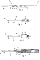
- Fig. 2 shows the probe 40 in detail. This is composed of a probe head 42, a probe body 43 and the coupling unit 70. The distal end 41 of the probe 40 thus forms the probe head 42, which is glued to the probe body 43. This probe body 43 is connected at the proximal end of the probe 40 to the coupling unit 70, which has a leaf spring 112 for triggering an accelerator 110 (FIG. Fig. 8-12 ).
- Fig. 3 indicates the probe 40 Fig. 2 with the support tube 60. This is, as already described, connected at its proximal end 61 with a connecting piece 64.
- the connecting piece 64 has a cylindrical shape and can be partially pushed over the coupling unit 70. When sliding over a portion of the leaf spring 112 snaps in a corresponding opening of the connector 64 a.
- a cavity 66 Inside the connecting piece 64 is a cavity 66 (see. Fig. 4 ), in which a coil spring 114 (see. Fig. 8 ) is arranged.
- this coil spring 114 is tensioned. Upon actuation of the leaf spring 114, this releases from the opening on the connector 64 and releases the stored in the tensioned coil spring 114 potential energy.
- the connector 64 with the support tube 60 is thereby accelerated relative to the coupling unit 70 with the probe 40 in the distal direction.
- the probe head 42 protrudes several millimeters beyond the distal end 62 of the support tube 60 in the locked state.
- the support tube 60 slides over the probe head 42.
- Fig. 4 shows a section along the longitudinal axis of the cryosurgical instrument 10.
- the cavity 66 which is formed in the locked state by the connecting piece 64 and the coupling unit 70 and extends annularly around the probe body 43, recognizable.
- the coil spring 114 is in Fig. 4 not shown.
- the probe 40 extends along the longitudinal axis of the cryosurgical instrument through the cavity 66.
- the probe 40 includes a gas supply line 50.
- the distal end 41 of the probe 40 is more precisely in FIG Fig. 5 shown, wherein the support tube 60 is pushed over the probe head 42.
- the probe 40 is guided in the support tube 60, wherein at least the probe head 42 in the support tube 60 can be received and released from this again.
- Fig. 5 shown a working channel 90 of an endoscope, in which the probe 40 is inserted with support tube 60.
- the probe head 42 has a substantially spherical configuration at the distal end, which provides a large area for contacting with the tissue 100.
- the shape of the probe head 42 aids in the adhesion of tissue 100 upon cooling.
- the distal end 62 of the support tube 60 has an abutment edge 63 which rests on the tissue surface for tissue removal.
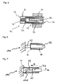
- FIG. 6 and 7 show the removal of the tissue sample 101 from the tissue to be treated 100.
- the probe head 42 projects beyond the distal end 62 of the support tube 60 and rests on the tissue 100 to be treated.
- the probe head 42 is thus in an extended position. Once the tissue is partially frozen to the probe head 42, this section, which finally the tissue sample 101, separated from the surrounding tissue 100 by the mutual movement of the probe 40 and support tube 60, and are taken up into the support tube 60.
- the probe head 42 and the tissue sample 101 are then located inside the support tube 60.
- This position shows Fig. 7 ,
- the support tube 60 is accelerated in the distal direction by the acceleration device 110 (see the direction of movement B). This is a relative movement to the probe 40.
- the distal end 62 of the support tube 60 strikes the tissue surface of the tissue 100 to be treated, this induces a pulse on the probe 40 comprising the probe body 43 and the probe head 42.
- This momentum depends against the direction of movement B of the support tube 60.
- the probe 40 is accelerated in the direction of movement A.
- the tissue sample 101 which is fixed to the probe head 42, is torn out of the tissue 100 to be treated.
- the 8 to 12 show numerous embodiments of the acceleration device 110. All exemplified acceleration devices 110 are integrated into a part of a handle device 20. Along the longitudinal axis of the accelerator devices 110 extends a probe channel 44, in which the probe 40 (not shown) is arranged. Preferably, the probe 40 is glued to the handle device 20.
- the connecting piece 64 can be displaced in the longitudinal direction relative to the handle device 20, as well as with respect to the probe 40 (see the direction of movement B). Permanently connected to the connector 64 is the support tube 60.
- FIGS 8 to 12 is still to be noted that contrary to the embodiment of Fig. 1 to 3 the connecting piece 64 protrudes into the gripping device.
- Fig. 8 shows a first embodiment of the accelerator 110, wherein the acceleration is ensured mechanically by the coil spring 114.
- the coil spring 114 is disposed in the cavity 66 formed by the handle device 20 and the connector 64.
- the coil spring 114 is applied both to the handle device 20 and the connecting piece 64.
- a triggering device 116 allows the engagement of the connector 64 in a cocked state. If necessary, the stored potential energy can be released by actuating the triggering device 116.
- Fig. 9 shows an electromagnetic accelerator. Annular coils 118, 118 'are arranged in the cavity 66, the probe channel 44 surrounding. A first electromagnetic coil 118 is connected to the handle assembly 20 and a second electromagnetic coil 118 'is connected to the connector 64. The electromagnetic coils 118, 118 'can be controlled so that they either attract or repel. As a result, the support tube 60 can be moved in the proximal or distal direction.
- Fig. 10 shows a pneumatic accelerator 110.
- a pneumatic accelerator 110 Around the probe channel 44 around an annular cylinder 120 is formed.
- a correspondingly shaped piston 122 which is connected via a linkage 123 with the connecting piece 64.
- the cylinder 120 which extends substantially longitudinally of the longitudinal axis of the accelerator 110, includes a first pressurized air conduit 124 that opens proximally into the piston 120 and a second pressurized air conduit 124 'that opens distally into the piston 120.
- the piston 122 By supplying compressed air via the first compressed air line 124 or via the second compressed air line 124 ', the piston 122 can be raised or lowered. As a result, the support tube 60 is moved.
- the acceleration of the support tube 60 can be controlled.
- Fig. 11 shows another electromagnetic accelerator 110.
- the movement of the support tube 60 is ensured by a motor 117 which is connected via a linkage 123 to the connector.
- Fig. 12 shows a pyrotechnic accelerator 110.
- the accelerator 110 is similar in construction to that of FIG Fig. 10 , It comprises an annular cylinder 120 and a corresponding annular piston 122 which is connected to the support tube 60. Inside the cylinder 120 is a pyrotechnic unit, which is triggered by an igniter 125. The released by the chemical reaction force is transmitted via piston 122 and linkage 123 to the connector 64.
Landscapes
- Health & Medical Sciences (AREA)
- Life Sciences & Earth Sciences (AREA)
- Surgery (AREA)
- Animal Behavior & Ethology (AREA)
- Public Health (AREA)
- Engineering & Computer Science (AREA)
- Biomedical Technology (AREA)
- Heart & Thoracic Surgery (AREA)
- Medical Informatics (AREA)
- Molecular Biology (AREA)
- Nuclear Medicine, Radiotherapy & Molecular Imaging (AREA)
- General Health & Medical Sciences (AREA)
- Veterinary Medicine (AREA)
- Otolaryngology (AREA)
- Pathology (AREA)
- Surgical Instruments (AREA)
- Liquid Crystal Substances (AREA)
- Lubricants (AREA)
- Silicon Polymers (AREA)
- Sampling And Sample Adjustment (AREA)
Description
- Die Erfindung betrifft ein kryochirurgisches Instrument zur Gewinnung einer Gewebeprobe.
- Die Kryobiopsie ist ein spezielles Verfahren im Bereich der Endoskopie, um Gewebeproben aus dem Körper eines Patienten zu entnehmen und somit die Diagnose über ein eventuelles Krankheitsbild nicht nur zu erleichtern, sondern auch zu verbessern.
- Der Entnahmeprozess verläuft wie folgt. Eine Kryosonde wird mit leichtem Druck auf das zu untersuchende Gewebe aufgelegt. Durch ein starkes Abkühlen des Sondenkopfs wird das Gewebe an dieser Stelle an die Sonde angefroren. Nach einer vorgegebenen Zeit wird das angefrorene Gewebe durch mechanischen Zug an der Sonde extrahiert.
- Das schnelle und starke Abkühlen des Sondenkopfs (ca. -50° C) wird durch den Joule-Thomson-Effekt erreicht. Hierbei macht man es sich zu Nutzen, dass sich Gas stark abkühlt, wenn es unter hohem Druck durch eine kleine Düse in einen großen Raum expandieren kann. Diese Expansion findet im Sondenkopf statt. Durch die Expansion des Gases entsteht Energie in Form von Kälte.
- Zur Durchführung einer Kryobiopsie sind unterschiedliche Geräte bekannt. Ein kryochirurgisches Gerät geht aus der
US 2003/0195436 A1 hervor. Dieses Instrument ist besonders zum Sichten und "Entkernen" von Tumoren geeignet. Das Instrument umfasst einen Handgriff, der mit einer Sonde verbunden ist. Die Sonde weist an ihrem distalen Ende einen Sondenkopf auf, der eine lanzenförmige Ausgestaltung hat. Der Sondenkopf lässt sich, wie beschrieben, stark abkühlen. Des Weiteren weist das Instrument eine Entnahmekanüle auf. Zur Entnahme wird das Gewebe mit der Lanze bzw. dem Sondenkopf aufgespießt und an diesem festgeeist. Durch ein Vorschieben der Entnahmekanüle wird ein Teil des festgeeisten Gewebes aus dem Tumor ausgeschnitten. Durch ein Abziehen des Instruments kann die ausgeschnittene Gewebeprobe entnommen werden. Um den Ausschneidevorgang zu erleichtern, weist dieUS 2003/0195436 A1 eine Beschleunigungsvorrichtung auf, die durch eine Feder angetrieben wird und die Kanüle mit einer vorbestimmten Kraft in das Gewebe treibt. - Zur Entnahme von Gewebeproben an Gewebeoberflächen ist dieses kryochirurgische Instrument nicht geeignet. Des Weiteren lassen sich hiermit nur relativ große Mengen von Gewebe entnehmen. Das entsprechende Verfahren verursacht eine tiefe Verletzung des zu behandelnden Gewebes.
- Ein weiteres kryochirurgisches Instrument ist durch die
EP 0 119 176 A bekannt, von der der Anspruch 1 abgeleitet wird. - Ausgehend von diesem Stand der Technik ist es Aufgabe der vorliegenden Erfindung, ein verbessertes kryochirurgisches Instrument bereit zu stellen. Das Instrument soll insbesondere dafür geeignet sein, Gewebeproben von Gewebewänden, insbesondere Schleimhäuten zu entnehmen. Dabei soll es zu einer möglichst geringen Verletzung des umliegenden Gewebes kommen und die Probe an sich sollte möglichst gut erhalten bleiben. Der Entnahmevorgang sollte einfach und effizient sein.
- Diese Aufgabe wird durch das kryochirurgische Instrument gemäß dem Anspruch 1 gelöst.
- Insbesondere wird die Aufgabe durch ein kryochirurgisches Instrument zur Gewinnung einer Gewebeprobe gelöst, wobei das Instrument Folgendes umfasst:
- eine Sonde mit einem Sondenkopf, der zur Fixierung eines Abschnitts einer Gewebewand durch eine Kühleinrichtung kühlbar ist;
- einen Stützschlauch mit einem Distalende, wobei die Sonde im Stützschlauch relativ zu diesem beweglich gelagert ist; und
- eine Beschleunigungsvorrichtung zur Beschleunigung des Stützschlauchs mit einer vorbestimmten Beschleunigungskraft relativ zur Sonde, wobei die Beschleunigungskraft derart gerichtet ist, dass die Sonde aus einer ausgefahrenen Position, in der der Sondenkopf das Distalende des Stützschlauchs überragt, in das Innere des Stützschlauchs zurückgezogen wird, wobei das Distalende des Stützschlauchs derart ausgestaltet ist, dass es bei einer Kontaktierung der Gewebewand eine Abrisskraft so induziert, dass durch die Sonde ein Abschnitt der Gewebewand herausgerissen wird.
- Ein zentraler Gedanke der vorliegenden Erfindung besteht also darin, dass die Gewebeprobe bzw. das Biopsat nicht aus der Gewebewand herausgeschnitten, sondern durch eine wohldefinierte Kraft herausgerissen wird. Erfindungsgemäß wird hierfür der Sondenkopf an der Gewebewand festgeeist und dann mit einer Abrisskraft in den Stützschlauch eingezogen. Um den Abrissvorgang erfolgreich durchführen zu können, ist es notwendig, einen geeigneten Impuls auf das angeeiste Gewebe auszuüben. Für den die Behandlung durchführenden Arzt ist es problematisch, den geeigneten Impuls mittels des Sondenkopfs auszuüben. Hierfür stellt die vorliegende Erfindung die Beschleunigungsvorrichtung bereit. Diese beschleunigt den Stützschlauch relativ zur Sonde. Durch das Auftreffen des beschleunigten Stützschlauchs auf die Gewebewand wird eine Abrisskraft freigesetzt, mittels derer der Sondenkopf einen Bereich der Gewebewand herausreißt. Die Abrisskraft wirkt im Wesentlichen in entgegen gesetzter Richtung wie die Beschleunigungskraft, die auf den Stützschlauch ausgeübt wird. Durch das Ausreißen kann eine vorteilhafte Abtrennung des Gewebes erzielt werden, bei der natürliche Zellgrenzen berücksichtigt werden.
- Der Sondenkopf kann einen Planarabschnitt zur Kontaktierung mit dem Gewebe umfassen. Dieser Abschnitt verläuft im Wesentlichen senkrecht zur Längsachse der Sonde und sollte derart ausgestaltet sein, dass eine möglichst großflächige Kontaktierung mit der Gewebewand möglich ist. Der Planarabschnitt kann entweder eben sein oder eine geeignete Oberflächenstruktur aufweisen. Beispielsweise könnte der Sondenkopf leicht abgerundet sein. Entscheidend ist, dass bei einem Andrücken des Sondenkopfs an das Gewebe eine großflächige Kontaktfläche hergestellt wird, die durch das Kühlen mit der Kühleinrichtung an dem Planarabschnitt festgeeist wird. Somit lässt sich die Abrisskraft problemlos auf das Gewebe übertragen.
- Die Beschleunigungsvorrichtung kann eine pneumatische und/oder eine elektromagnetische und/oder eine mechanische und/oder eine pyrotechnische Beschleunigungsvorrichtung umfassen. Somit kann eine vordefinierte Beschleunigungskraft bereitgestellt werden. Die definierte Abrisskraft führt bei dem Auslösen von Biopsat zu vorteilhaften Ergebnissen. Der Arzt muss den geeigneten Impuls nicht manuell festlegen. Bei jeder Biopsie wird die gleiche Menge an Kraft aufgebracht.
- Die Beschleunigungsvorrichtung kann eine Feder umfassen. Die Feder kann vor dem Eingriff gespannt werden und speichert eine definierte Menge an potentieller Energie.
- Die Beschleunigungsvorrichtung kann ein Verbindungsstück umfassen, das mit dem Stützschlauch in Wirkverbindung steht und mittelbar oder unmittelbar an die Sonde angekoppelt ist, wobei das Verbindungsstück ein Spannelement umfasst, das eine vorbestimmte Menge an potentieller Energie speichert. Vorzugsweise wird die oben beschriebene Feder im Inneren des Verbindungsstückes gelagert.
- Die Beschleunigungsvorrichtung kann eine Auslösevorrichtung umfassen, die die potentielle Energie freisetzt. Somit kann der Entnahmevorgang per Knopfdruck durchgeführt werden.
- Das kryochirurgische Instrument kann ein Griffstück umfassen, wobei die Sonde und/oder der Stützschlauch abnehmbar an dem Griffstück angekoppelt ist. Somit ist es möglich, Stützschlauch und/oder Sonde als Einweg-Geräte auszugestalten, während das Griffstück wieder verwendet werden kann.
- Das kryochirurgische Instrument kann derart ausgestaltet werden, dass der Überstand des Sondenkopfs in der ausgefahrenen Position mindestens 5, insbesondere 15 mm beträgt. Somit wird eine gute Einsicht auf die Sondenspitze sichergestellt. Der Arzt hat beim Gefriervorgang eine gute Sicht auf den Sondenkopf und dessen Position. Als Überstand wird der Abstand des Sondenkopfs zur Abschlussebene des Distalendes des Stützschlauchs bezeichnet.
- Der Stützschlauch kann aus Kunststoff gefertigt sein. Durch das Verwenden von Kunststoff kann eine ausreichende Knickfestigkeit des Stützschlauchs erzielt werden, so dass dieser beim Abrissvorgang nicht einknickt. Des Weiteren hat Kunststoff den Vorteil, dass es sich hierbei um einen thermischen Isolator handelt. Somit wird verhindert, dass das Distalende des Stützschlauchs beim Abkühlen des Sondenkopfs am Gewebe festfriert.
- Der Sondenkopf kann aus einem metallischen Werkstoff hergestellt sein.
- Bevorzugte Ausführungsformen der Erfindung ergeben sich aus den Unteransprüchen.
- Nachfolgend wird die Erfindung anhand von Ausführungsbeispielen beschrieben, die anhand der Abbildungen näher erläutert werden. Hierbei zeigen:
- - Fig. 1
- ein erfindungsgemäßes kryochirurgisches Instrument;
- - Fig. 2
- eine Kryosonde;
- - Fig. 3
- die Kryosonde aus
Fig. 2 mit einem Stützschlauch; - - Fig. 4
- einen Querschnitt durch das kryochirurgische Instrument aus
Fig. 1 ; - - Fig. 5
- das distale Ende der in einem Arbeitskanal eines Endoskops geführten Sonde mit Stützschlauch im Schnitt;
- - Fig. 6 und 7
- den erfindungsgemäßen Entnahmevorgang einer Gewebeprobe;
- - Fig. 8
- eine mechanische Beschleunigungsvorrichtung;
- - Fig. 9
- eine elektromagnetische Beschleunigungsvorrichtung;
- - Fig. 10
- eine pneumatische Beschleunigungsvorrichtung;
- - Fig. 11
- eine Beschleunigungsvorrichtung mit Elektromotor; und
- - Fig. 12
- eine pyrotechnische Beschleunigungsvorrichtung.
- In der nachfolgenden Beschreibung werden für gleiche und gleich wirkende Teile dieselben Bezugsziffern verwendet.
- Das erfindungsgemäße kryochirurgische Instrument besteht aus drei wesentlichen Baugruppen. Diese sind in
Fig. 1 dargestellt: - Der Stützschlauch 60 mit Verbindungsstück 64, der als Schutz und zum Herauslösen des Biopsats dient.
Der Stützschlauch 60 ist mittels Verbindungsstück 64 beweglich an einer Kupplungseinheit 70 fixiert. - Die Kupplungseinheit 70 mit Sonde 40.
Die Kupplungseinheit 70, umfassend eine Blattfeder 112, bildet einen Teil der Beschleunigungsvorrichtung 110 (Fig. 8-12 ). - Eine Griffeinrichtung 20 zum Halten des kryochirurgischen Instruments 10.
- Durch Kupplungen zwischen den einzelnen Baugruppen lassen sich die einzelnen Teile des kryochirurgischen Instruments 10 abnehmen und können nach Bedarf ausgetauscht oder gereinigt werden. Somit ist das System flexibel und für die Handhabung attraktiver, als komplett geschlossene Systeme. Die Griffeinrichtung 20 hat ein proximales Ende 21 und ein distales Ende 22. Die Kupplungseinheit 70 wird am distalen Ende 22 mit der Griffeinrichtung 20 verbunden.
-
Fig. 2 zeigt die Sonde 40 im Detail. Diese setzt sich aus einem Sondenkopf 42, einem Sondenkörper 43 und der Kupplungseinheit 70 zusammen. Das distale Ende 41 der Sonde 40 bildet also der Sondenkopf 42, der mit dem Sondenkörper 43 verklebt ist. Dieser Sondenkörper 43 ist am proximalen Ende der Sonde 40 mit der Kupplungseinheit 70 verbunden, die eine Blattfeder 112 zum Auslösen einer Beschleunigungseinrichtung 110 (Fig. 8-12 ) umfasst. -
Fig. 3 zeigt die Sonde 40 ausFig. 2 mit dem Stützschlauch 60. Dieser ist, wie bereits beschrieben, an seinem proximalen Ende 61 mit einem Verbindungsstück 64 verbunden. Das Verbindungsstück 64 hat eine zylindrische Form und lässt sich teilweise über die Kupplungseinheit 70 schieben. Beim Überschieben rastet ein Abschnitt der Blattfeder 112 in eine korrespondierende Öffnung des Verbindungsstücks 64 ein. Im Inneren des Verbindungsstücks 64 befindet sich ein Hohlraum 66 (vgl.Fig. 4 ), in dem eine Spiralfeder 114 (vgl.Fig. 8 ) angeordnet ist. Durch das Überziehen des Verbindungsstücks 64 wird diese Spiralfeder 114 gespannt. Bei einer Betätigung der Blattfeder 114 löst sich diese aus der Öffnung am Verbindungsstück 64 und setzt die in der gespannten Spiralfeder 114 gespeicherte potentielle Energie frei. Das Verbindungsstück 64 mit dem Stützschlauch 60 wird hierdurch gegenüber der Kupplungseinheit 70 mit der Sonde 40 in distale Richtung beschleunigt. Wie inFig. 3 gezeigt, ragt im eingerasteten Zustand der Sondenkopf 42 mehrere Millimeter über das Distalende 62 des Stützschlauchs 60 heraus. Beim Auslösen der vorgespannten Feder 114 schiebt sich der Stützschlauch 60 über den Sondenkopf 42. -
Fig. 4 zeigt einen Schnitt entlang der Längsachse des kryochirurgischen Instruments 10. In diesem Schnitt ist der Hohlraum 66, der im eingerasteten Zustand durch das Verbindungsstück 64 und die Kupplungseinheit 70 gebildet wird und sich ringförmig um den Sondenkörper 43 erstreckt, erkennbar. Die Spiralfeder 114 ist inFig. 4 nicht dargestellt. - Die Sonde 40 verläuft entlang der Längsachse des kryochirurgischen Instruments durch den Hohlraum 66. Zur Kühlung des Sondenkopfs 42 enthält die Sonde 40 eine Gaszuführleitung 50. Das distale Ende 41 der Sonde 40 ist genauer in der
Fig. 5 dargestellt, wobei der Stützschlauch 60 über den Sondenkopf 42 geschoben ist. Die Sonde 40 ist in dem Stützschlauch 60 geführt, wobei mindestens der Sondenkopf 42 in dem Stützschlauch 60 aufnehmbar und aus diesem wieder freigebbar ist. Ferner ist inFig. 5 ein Arbeitskanal 90 eines Endoskops gezeigt, in welchen die Sonde 40 mit Stützschlauch 60 eingeführt ist. Der Sondenkopf 42 weist am distalen Ende eine im Wesentlichen kugelförmige Ausbildung auf, die einen großflächigen Bereich zur Kontaktierung mit dem Gewebe 100 bereitstellt. Die Form des Sondenkopfes 42 unterstützt die Adhäsion von Gewebe 100 bei der Abkühlung. Das distale Ende 62 des Stützschlauchs 60 hat eine Aufsetzkante 63, die zur Gewebeentnahme auf der Gewebeoberfläche aufsetzt. -
Fig. 6 und 7 zeigen die Entnahme der Gewebeprobe 101 von dem zu behandelnden Gewebe 100. In derFig. 6 überragt der Sondenkopf 42 das distale Ende 62 des Stützschlauchs 60 und liegt auf dem zu behandelnden Gewebe 100 auf. Der Sondenkopf 42 befindet sich also in einer ausgefahrenen Position. Sobald das Gewebe bereichsweise an den Sondenkopf 42 angefroren ist, kann dieser Abschnitt, der schließlich die Gewebeprobe 101 bildet, durch das Gegeneinanderbewegen von Sonde 40 und Stützschlauch 60 von dem umliegenden Gewebe 100 abgetrennt und in den Stützschlauch 60 eingeholt werden. Der Sondenkopf 42 und die Gewebeprobe 101 befinden sich dann im Inneren des Stützschlauchs 60. Diese Position zeigtFig. 7 . Für die erfindungsgemäße Entnahme der Gewebeprobe 101 wird der Stützschlauch 60 durch die Beschleunigungsvorrichtung 110 in distaler Richtung beschleunigt (vgl. Bewegungsrichtung B). Hierbei handelt es sich um eine Relativbewegung zur Sonde 40. Sobald das Distalende 62 des Stützschlauchs 60 auf die Gewebeoberfläche des zu behandelnden Gewebes 100 trifft, induziert dies einen Impuls auf die Sonde 40, umfassend den Sondenkörper 43 und den Sondenkopf 42. Dieser Impuls richtet sich entgegen der Bewegungsrichtung B des Stützschlauchs 60. Somit wird die Sonde 40 in die Bewegungsrichtung A beschleunigt. Die Gewebeprobe 101, die am Sondenkopf 42 fixiert ist, wird aus dem zu behandelnden Gewebe 100 herausgerissen. - Die
Fig. 8 bis 12 zeigen zahlreiche Ausgestaltungen der Beschleunigungsvorrichtung 110. Sämtliche beispielhaft dargestellten Beschleunigungsvorrichtungen 110 sind in einen Teil einer Griffeinrichtung 20 integriert. Entlang der Längsachse der Beschleunigungsvorrichtungen 110 verläuft ein Sondenkanal 44, in dem die Sonde 40 (nicht dargestellt) angeordnet ist. Vorzugsweise ist die Sonde 40 mit der Griffeinrichtung 20 verklebt. Das Verbindungsstück 64 lässt sich gegenüber der Griffeinrichtung 20, so wie gegenüber der Sonde 40 in Längsrichtung verschieben (vgl. Bewegungsrichtung B). Fest mit dem Verbindungsstück 64 verbunden ist der Stützschlauch 60. Zu den beispielhaften Ausführungsformen aus denFig. 8 bis 12 ist noch anzumerken, dass hier entgegen dem Ausführungsbeispiel ausFig. 1 bis 3 das Verbindungsstück 64 in die Griffeinrichtung hineinragt. -
Fig. 8 zeigt ein erstes Ausführungsbeispiel der Beschleunigungsvorrichtung 110, wobei die Beschleunigung mechanisch durch die Spiralfeder 114 gewährleistet wird. Die Spiralfeder 114 ist in dem Hohlraum 66, der durch die Griffeinrichtung 20 und das Verbindungsstück 64 gebildet wird, angeordnet. Die Spiralfeder 114 setzt sowohl an der Griffeinrichtung 20 und dem Verbindungsstück 64 an. Eine Auslösevorrichtung 116 ermöglicht das Einrasten des Verbindungsstücks 64 in einem gespannten Zustand. Bei Bedarf kann die gespeicherte potentielle Energie durch das Betätigen der Auslösevorrichtung 116 freigesetzt werden. -
Fig. 9 zeigt eine elektromagnetische Beschleunigungsvorrichtung. Ringförmige Spulen 118, 118' sind in dem Hohlraum 66, den Sondenkanal 44 umgebend angeordnet. Eine erste elektromagnetische Spule 118 ist mit der Griffeinrichtung 20 und eine zweite elektromagnetische Spule 118' mit dem Verbindungsstück 64 verbunden. Die elektromagnetischen Spulen 118, 118' lassen sich derart ansteuern, dass sie sich entweder anziehen oder abstoßen. Hierdurch kann der Stützschlauch 60 in proximale oder distale Richtung bewegt werden. -
Fig. 10 zeigt eine pneumatische Beschleunigungsvorrichtung 110. Um den Sondenkanal 44 herum ist ein ringförmiger Zylinder 120 ausgebildet. In diesem Zylinder 120 befindet sich ein entsprechend geformter Kolben 122, der über ein Gestänge 123 mit dem Verbindungsstück 64 verbunden ist. Der Zylinder 120, der sich im Wesentlichen längs zur Längsachse der Beschleunigungsvorrichtung 110 erstreckt, umfasst eine erste Druckluftleitung 124, die proximal in den Kolben 120 mündet, und eine zweite Druckluftleitung 124', die distal in den Kolben 120 mündet. Durch ein Zuführen von Druckluft über die erste Druckluftleitung 124 oder über die zweite Druckluftleitung 124' lässt sich der Kolben 122 heben bzw. senken. Hierdurch wird der Stützschlauch 60 bewegt. Durch eine entsprechende Dosierung der Druckluft lässt sich die Beschleunigung des Stützschlauchs 60 steuern. -
Fig. 11 zeigt eine weitere elektromagnetische Beschleunigungsvorrichtung 110. Die Bewegung des Stützschlauchs 60 wird durch einen Motor 117, der über ein Gestänge 123 mit dem Verbindungsstück verbunden ist, gewährleistet. -
Fig. 12 zeigt eine pyrotechnische Beschleunigungsvorrichtung 110. Die Beschleunigungsvorrichtung 110 ist ähnlich aufgebaut wie die ausFig. 10 . Sie umfasst einen ringförmigen Zylinder 120 und einen entsprechend ringförmigen Kolben 122, der mit dem Stützschlauch 60 verbunden ist. Im Inneren des Zylinders 120 befindet sich eine pyrotechnische Einheit, die durch eine Zündeinrichtung 125 auslösbar ist. Die durch die chemische Reaktion freigesetzte Kraft wird über Kolben 122 und Gestänge 123 auf das Verbindungsstück 64 übertragen. -
- 10
- Kryochirurgisches Instrument
- 20
- Griffeinrichtung
- 21
- proximales Ende der Griffeinrichtung
- 22
- distales Ende der Griffeinrichtung
- 40
- Sonde
- 41
- distales Ende der Sonde
- 42
- Sondenkopf
- 43
- Sondenkörper
- 44
- Sondenkanal
- 50
- Gaszuführleitung
- 60
- Stützschlauch
- 61
- proximales Ende des Stützschlauchs
- 62
- distales Ende des Stützschlauchs
- 63
- Aufsetzkante
- 64
- Verbindungsstück
- 65
- Halteeinrichtung
- 66
- Hohlraum
- 70
- Kupplungseinheit
- 90
- Arbeitskanal eines Endoskops
- 100
- zu behandelndes Gewebe
- 101
- Gewebeprobe
- 110
- Beschleunigungsvorrichtung
- 112
- Blattfeder
- 114
- Spiralfeder
- 116
- Auslösevorrichtung
- 117
- Motor
- 118, 118'
- elektromagnetische Spule
- 120
- Zylinder
- 122
- Kolben
- 123
- Gestänge
- 124, 124'
- Druckluftleitung
- 125
- Zündeinrichtung
- A
- Bewegungsrichtung der Sonde
- B
- Bewegungsrichtung der Stützeinrichtung
Claims (10)
- Kryochirurgisches Instrument zur Gewinnung einer Gewebeprobe (101), umfassend:- eine Sonde (40) mit einem Sondenkopf (42) der zur Fixierung eines Abschnitts einer Gewebewand durch eine Kühleinrichtung kühlbar ist;- einen Stützschlauch (60) mit einem Distalende (62), wobei die Sonde (40) in diesem Stützschlauch (60) relativ zu diesem beweglich gelagert ist;gekennzeichnet durch:eine Beschleunigungsvorrichtung (110) zur Beschleunigung des Stützschlauchs (60) mit einer vorbestimmten Beschleunigungskraft relativ zur Sonde, wobei die Beschleunigungskraft derart gerichtet ist, dass die Sonde (40) aus einer ausgefahrenen Position, in der der Sondenkopf (42) das Distalende (62) des Stützschlauches (60) überragt, im Inneren des Stützschlauches (60) zu liegen kommt, wobei das Distalende (62) des Stützschlauches (60) derart ausgestaltet ist,dass es nach einer Beschleunigung durch die Beschleunigungsvorrichtung (110) bei einer Kontaktierung der Gewebewand eine Abrisskraft so induziert, dass durch die Sonde (40) ein Abschnitt der Gewebewand herausgerissen wird.
- Kryochirurgisches Instrument nach Anspruch 1,
dadurch gekennzeichnet, dass
der Sondenkopf (42) im Wesentlichen einen Planarabschnitt zur Kontaktierung mit der Gewebewand umfasst. - Kryochirurgisches Instrument nach einem der vorhergehenden Ansprüche,
dadurch gekennzeichnet, dass
die Beschleunigungsvorrichtung (110) eine pneumatische und/oder eine elektromagnetische und/oder eine mechanische und/oder pyrotechnische Beschleunigungsvorrichtung (110) umfasst. - Kryochirurgisches Instrument nach einem der vorhergehenden Ansprüche,
dadurch gekennzeichnet, dass
die Beschleunigungsvorrichtung (110) eine Feder (114) zur Speicherung einer vorbestimmten Menge an potentieller Energie umfasst. - Kryochirurgisches Instrument nach einem der vorhergehenden Ansprüche,
dadurch gekennzeichnet, dass
die Beschleunigungsvorrichtung (110) ein Verbindungsstück (64) umfasst, das mit dem Stützschlauch (60) in Wirkverbindung steht und mittelbar oder unmittelbar an die Sonde (40) angekuppelt ist, wobei das Verbindungsstück (64) ein Spannelement umfasst, das eine vorbestimmte Menge an potentieller Energie speichert. - Kryochirurgisches Instrument nach Anspruch 5,
dadurch gekennzeichnet, dass
die Beschleunigungsvorrichtung (110) eine Auslösevorrichtung (116) umfasst, die die potentielle Energie freisetzt. - Kryochirurgisches Instrument nach einem der vorhergehenden Ansprüche,
gekennzeichnet durch
ein Griffstück, wobei die Sonde (40) abnehmbar an das Griffstück angekuppelt ist. - Kryochirurgisches Instrument nach einem der vorhergehenden Ansprüche,
dadurch gekennzeichnet, dass
der Stützschlauch (60) und die Sonde (40) derart bemessen sind, dass der Überstand des Sondenkopfs (42) in der ausgefahrenen Position mindestens 5 Millimeter (mm) beträgt. - Kryochirurgisches Instrument nach einem der vorhergehenden Ansprüche,
dadurch gekennzeichnet, dass
der Stützschlauch (60) aus Kunststoff ist. - Kryochirurgisches Instrument nach einem der vorhergehenden Ansprüche,
dadurch gekennzeichnet, dass
der Sondenkopf (42) aus einem metallischen Werkstoff ist.
Applications Claiming Priority (3)
| Application Number | Priority Date | Filing Date | Title |
|---|---|---|---|
| DE102007029387 | 2007-06-26 | ||
| DE102008026635A DE102008026635B4 (de) | 2007-06-26 | 2008-06-04 | Kryobiopsiesonde |
| PCT/EP2008/005010 WO2009000477A1 (de) | 2007-06-26 | 2008-06-20 | Kryobiopsiesonde |
Publications (2)
| Publication Number | Publication Date |
|---|---|
| EP2170197A1 EP2170197A1 (de) | 2010-04-07 |
| EP2170197B1 true EP2170197B1 (de) | 2011-04-06 |
Family
ID=40076186
Family Applications (1)
| Application Number | Title | Priority Date | Filing Date |
|---|---|---|---|
| EP08773560A Not-in-force EP2170197B1 (de) | 2007-06-26 | 2008-06-20 | Kryobiopsiesonde |
Country Status (7)
| Country | Link |
|---|---|
| US (1) | US8216153B2 (de) |
| EP (1) | EP2170197B1 (de) |
| JP (1) | JP5431315B2 (de) |
| CN (1) | CN101711133B (de) |
| AT (1) | ATE504252T1 (de) |
| DE (2) | DE102008026635B4 (de) |
| WO (1) | WO2009000477A1 (de) |
Families Citing this family (10)
| Publication number | Priority date | Publication date | Assignee | Title |
|---|---|---|---|---|
| GB2487199A (en) * | 2011-01-11 | 2012-07-18 | Creo Medical Ltd | Electrosurgical device with fluid conduit |
| US10603114B2 (en) | 2014-04-17 | 2020-03-31 | Koninklijke Philips N.V. | Method and system for detecting a fast moving surgical device |
| CN105496472B (zh) * | 2016-01-26 | 2019-03-19 | 陆海鹤 | 弹力式细胞采集器 |
| PL3323366T3 (pl) | 2016-11-18 | 2021-01-25 | Erbe Elektromedizin Gmbh | Kriosonda i sposób jej wytwarzania |
| EP3758636B1 (de) * | 2018-03-02 | 2026-04-08 | The General Hospital Corporation | Systeme zur kryogenen biopsieprobenahme |
| EP3597112A1 (de) | 2018-07-17 | 2020-01-22 | Erbe Elektromedizin GmbH | Biopsatbergeeinrichtung |
| EP3769706A1 (de) | 2019-07-23 | 2021-01-27 | Erbe Elektromedizin GmbH | Kryosonde |
| WO2021026467A1 (en) * | 2019-08-07 | 2021-02-11 | Ictero Medical, Inc. | Systems, devices, and methods for ablation and defunctionalization of a gallbladder |
| EP4196028A4 (de) | 2020-08-14 | 2024-09-18 | Ictero Medical, Inc. | Systeme, vorrichtungen und verfahren zur ablation und defunktionalisierung einer gallenblase |
| CN121587780B (zh) * | 2026-01-29 | 2026-04-17 | 浙江伽奈维医疗科技有限公司 | 一种机械式冷冻旋切活检针 |
Family Cites Families (29)
| Publication number | Priority date | Publication date | Assignee | Title |
|---|---|---|---|---|
| US3439680A (en) * | 1965-04-12 | 1969-04-22 | Univ Northwestern | Surgical instrument for cataract removal |
| SE432353B (sv) * | 1983-02-11 | 1984-04-02 | Lkb Produkter Ab | Forfarande for att snitta ett medelst en nedkyld provtagningsnal taget, fryst vevnadsprov i en mikrotom samt provtagningsnal anvend vid forfarandet |
| US5353804A (en) * | 1990-09-18 | 1994-10-11 | Peb Biopsy Corporation | Method and device for percutaneous exisional breast biopsy |
| US5133360A (en) * | 1991-03-07 | 1992-07-28 | Spears Colin P | Spears retriever |
| JPH0636803B2 (ja) * | 1992-04-30 | 1994-05-18 | 株式会社エイコー・エンジニアリング | 外科用生体内凍結手術具及び生体組織採取装置 |
| US5526822A (en) * | 1994-03-24 | 1996-06-18 | Biopsys Medical, Inc. | Method and apparatus for automated biopsy and collection of soft tissue |
| US5868673A (en) * | 1995-03-28 | 1999-02-09 | Sonometrics Corporation | System for carrying out surgery, biopsy and ablation of a tumor or other physical anomaly |
| US5910104A (en) * | 1996-12-26 | 1999-06-08 | Cryogen, Inc. | Cryosurgical probe with disposable sheath |
| US6032675A (en) * | 1997-03-17 | 2000-03-07 | Rubinsky; Boris | Freezing method for controlled removal of fatty tissue by liposuction |
| US6488673B1 (en) * | 1997-04-07 | 2002-12-03 | Broncus Technologies, Inc. | Method of increasing gas exchange of a lung |
| DE19806693A1 (de) * | 1998-02-18 | 1999-08-19 | Daum Gmbh | Tumortherapie |
| US6546932B1 (en) * | 1999-04-05 | 2003-04-15 | Cryocath Technologies Inc. | Cryogenic method and apparatus for promoting angiogenesis |
| US6379348B1 (en) * | 2000-03-15 | 2002-04-30 | Gary M. Onik | Combined electrosurgical-cryosurgical instrument |
| US6494844B1 (en) * | 2000-06-21 | 2002-12-17 | Sanarus Medical, Inc. | Device for biopsy and treatment of breast tumors |
| US6527765B2 (en) * | 2000-10-06 | 2003-03-04 | Charles D. Kelman | Cryogenic surgical system and method of use in removal of tissue |
| JP4108473B2 (ja) * | 2000-10-16 | 2008-06-25 | サナルス・メディカル・インコーポレイテッド | 腫瘍の生体検査装置 |
| US6540694B1 (en) * | 2000-10-16 | 2003-04-01 | Sanarus Medical, Inc. | Device for biopsy tumors |
| EP1429679A2 (de) * | 2001-09-27 | 2004-06-23 | Galil Medical Ltd | Gerät und verfahren für die kryochirurgische behandlung von brusttumoren |
| US8123698B2 (en) * | 2002-10-07 | 2012-02-28 | Suros Surgical Systems, Inc. | System and method for minimally invasive disease therapy |
| JP4487055B2 (ja) * | 2003-09-17 | 2010-06-23 | 学校法人慶應義塾 | 組織穿孔用具、及び生検システム |
| US7402140B2 (en) * | 2004-02-12 | 2008-07-22 | Sanarus Medical, Inc. | Rotational core biopsy device with liquid cryogen adhesion probe |
| US20070043342A1 (en) * | 2005-08-16 | 2007-02-22 | Galil Medical Ltd. | Cryoprobe with reduced adhesion to frozen tissue, and cryosurgical methods utilizing same |
| US20070055173A1 (en) | 2005-08-23 | 2007-03-08 | Sanarus Medical, Inc. | Rotational core biopsy device with liquid cryogen adhesion probe |
| US20070191732A1 (en) * | 2006-02-10 | 2007-08-16 | Voegele James W | Cryogenic probe |
| US20070287933A1 (en) * | 2006-06-08 | 2007-12-13 | Chris Phan | Tissue debulking device and method of using the same |
| DE102007020582A1 (de) * | 2006-12-19 | 2008-06-26 | Erbe Elektromedizin Gmbh | Kryochirurgisches Instrument und Verfahren zum Abtrennen einer Gewebeprobe von umliegendem Gewebe eines zu behandelnden biologischen Gewebes |
| WO2008111070A2 (en) * | 2007-03-12 | 2008-09-18 | David Tolkowsky | Devices and methods for performing medical procedures in tree-like luminal structures |
| DE102008024946B4 (de) * | 2008-05-23 | 2010-07-22 | Erbe Elektromedizin Gmbh | Kryochirurgisches Instrument zur Gewinnung einer Gewebeprobe |
| DE102008061063B4 (de) * | 2008-10-29 | 2016-12-29 | Erbe Elektromedizin Gmbh | Kryosonde, Kryochirurgisches Gerät |
-
2008
- 2008-06-04 DE DE102008026635A patent/DE102008026635B4/de not_active Expired - Fee Related
- 2008-06-20 EP EP08773560A patent/EP2170197B1/de not_active Not-in-force
- 2008-06-20 JP JP2010513738A patent/JP5431315B2/ja not_active Expired - Fee Related
- 2008-06-20 DE DE502008003121T patent/DE502008003121D1/de active Active
- 2008-06-20 US US12/666,147 patent/US8216153B2/en active Active
- 2008-06-20 WO PCT/EP2008/005010 patent/WO2009000477A1/de not_active Ceased
- 2008-06-20 AT AT08773560T patent/ATE504252T1/de active
- 2008-06-20 CN CN2008800220451A patent/CN101711133B/zh active Active
Also Published As
| Publication number | Publication date |
|---|---|
| JP5431315B2 (ja) | 2014-03-05 |
| EP2170197A1 (de) | 2010-04-07 |
| DE102008026635B4 (de) | 2010-10-28 |
| DE102008026635A1 (de) | 2009-01-02 |
| WO2009000477A1 (de) | 2008-12-31 |
| CN101711133A (zh) | 2010-05-19 |
| ATE504252T1 (de) | 2011-04-15 |
| DE502008003121D1 (de) | 2011-05-19 |
| JP2010531178A (ja) | 2010-09-24 |
| US20100198202A1 (en) | 2010-08-05 |
| US8216153B2 (en) | 2012-07-10 |
| CN101711133B (zh) | 2011-09-14 |
Similar Documents
| Publication | Publication Date | Title |
|---|---|---|
| DE102008026635B4 (de) | Kryobiopsiesonde | |
| EP2229887B1 (de) | Lanzettensystem mit Sterilschutz | |
| EP2114276B1 (de) | Kryochirurgisches instrument zum abtrennen einer gewebeprobe von umliegendem gewebe eines zu behandelnden biologischen gewebes | |
| DE69227382T2 (de) | Angetriebener Trokar | |
| EP0983021B1 (de) | Endoskop für die Feinnadelaspriationsbiopsie | |
| DE69633750T2 (de) | Vorrichtung zur automatischen Biopsie- und Weichgewebeentnahme | |
| DE69434857T2 (de) | Instrument zum Sammeln von mehreren Biopsieproben | |
| EP2326272B1 (de) | Kryochirurgisches instrument zur gewinnung einer gewebeprobe | |
| EP0010321A1 (de) | Vorrichtung zur einhändigen Bedienung eines Biopsiegerätes | |
| DE102007013426A1 (de) | Vorrichtung zum Befestigen eines chirurgischen Fadens an einem Knochen | |
| EP1894529B1 (de) | Vorrichtung zum Einführen zumindest eines Ankerstücks in einen Hohlraum eines Lebewesens | |
| DE102021108057A1 (de) | Drehbare gewebeprobennahmevorrichtung | |
| EP2129297B1 (de) | Instrument für die medizinische untersuchung von engen körperkanälen | |
| DE102019105198A1 (de) | Katheteranordnung mit versatzvorrichtung zur gewebeprobenahme | |
| DE202004012970U1 (de) | Pränatale Biopsievorrichtung für die Entnahme von Flüssigkeits- und/oder Gewebeproben | |
| DE102012219342A1 (de) | Endoskopie- und Biopsie-Einwegsystem | |
| DE102009060921A1 (de) | Punktionsnadelsystem | |
| DE69433986T2 (de) | Visuell gesteuerter trokar | |
| EP3071114A1 (de) | Probennahmeeinheit, probennahmevorrichtung und verfahren zur entnahme einer probe | |
| DE202012011472U1 (de) | Endoskopievorrichtung | |
| EP4183357B1 (de) | Medizinisches instrument | |
| DE4421468C2 (de) | Vorrichtung zur Schleimhautsekretgewinnung aus Hohlorganen und inneren Körperhöhlen | |
| DE202008010236U1 (de) | Vorrichtung zum Einbringen eines endoskopischen Operationsschaftes | |
| DE102005050347A1 (de) | Biopsienadel mit Schneid-/Haltemechanismus | |
| DE202008010237U1 (de) | Vorrichtung zum Schaffen eines Zugangs für einen endoskopischen Eingriff |
Legal Events
| Date | Code | Title | Description |
|---|---|---|---|
| PUAI | Public reference made under article 153(3) epc to a published international application that has entered the european phase |
Free format text: ORIGINAL CODE: 0009012 |
|
| 17P | Request for examination filed |
Effective date: 20100122 |
|
| AK | Designated contracting states |
Kind code of ref document: A1 Designated state(s): AT BE BG CH CY CZ DE DK EE ES FI FR GB GR HR HU IE IS IT LI LT LU LV MC MT NL NO PL PT RO SE SI SK TR |
|
| AX | Request for extension of the european patent |
Extension state: AL BA MK RS |
|
| RIN1 | Information on inventor provided before grant (corrected) |
Inventor name: VOIGTLAENDER, MATTHIAS Inventor name: FISCHER, KLAUS Inventor name: SZYRACH, MARA Inventor name: SCHAELLER, DANIEL Inventor name: SIGLE, IRINA |
|
| DAX | Request for extension of the european patent (deleted) | ||
| GRAP | Despatch of communication of intention to grant a patent |
Free format text: ORIGINAL CODE: EPIDOSNIGR1 |
|
| GRAS | Grant fee paid |
Free format text: ORIGINAL CODE: EPIDOSNIGR3 |
|
| GRAA | (expected) grant |
Free format text: ORIGINAL CODE: 0009210 |
|
| AK | Designated contracting states |
Kind code of ref document: B1 Designated state(s): AT BE BG CH CY CZ DE DK EE ES FI FR GB GR HR HU IE IS IT LI LT LU LV MC MT NL NO PL PT RO SE SI SK TR |
|
| REG | Reference to a national code |
Ref country code: GB Ref legal event code: FG4D Free format text: NOT ENGLISH |
|
| REG | Reference to a national code |
Ref country code: CH Ref legal event code: EP |
|
| REG | Reference to a national code |
Ref country code: IE Ref legal event code: FG4D |
|
| REF | Corresponds to: |
Ref document number: 502008003121 Country of ref document: DE Date of ref document: 20110519 Kind code of ref document: P |
|
| REG | Reference to a national code |
Ref country code: DE Ref legal event code: R096 Ref document number: 502008003121 Country of ref document: DE Effective date: 20110519 |
|
| REG | Reference to a national code |
Ref country code: NL Ref legal event code: VDEP Effective date: 20110406 |
|
| PG25 | Lapsed in a contracting state [announced via postgrant information from national office to epo] |
Ref country code: SI Free format text: LAPSE BECAUSE OF FAILURE TO SUBMIT A TRANSLATION OF THE DESCRIPTION OR TO PAY THE FEE WITHIN THE PRESCRIBED TIME-LIMIT Effective date: 20110406 |
|
| LTIE | Lt: invalidation of european patent or patent extension |
Effective date: 20110406 |
|
| REG | Reference to a national code |
Ref country code: IE Ref legal event code: FD4D |
|
| PG25 | Lapsed in a contracting state [announced via postgrant information from national office to epo] |
Ref country code: HR Free format text: LAPSE BECAUSE OF FAILURE TO SUBMIT A TRANSLATION OF THE DESCRIPTION OR TO PAY THE FEE WITHIN THE PRESCRIBED TIME-LIMIT Effective date: 20110406 Ref country code: PT Free format text: LAPSE BECAUSE OF FAILURE TO SUBMIT A TRANSLATION OF THE DESCRIPTION OR TO PAY THE FEE WITHIN THE PRESCRIBED TIME-LIMIT Effective date: 20110808 Ref country code: SE Free format text: LAPSE BECAUSE OF FAILURE TO SUBMIT A TRANSLATION OF THE DESCRIPTION OR TO PAY THE FEE WITHIN THE PRESCRIBED TIME-LIMIT Effective date: 20110406 Ref country code: NO Free format text: LAPSE BECAUSE OF FAILURE TO SUBMIT A TRANSLATION OF THE DESCRIPTION OR TO PAY THE FEE WITHIN THE PRESCRIBED TIME-LIMIT Effective date: 20110706 Ref country code: LT Free format text: LAPSE BECAUSE OF FAILURE TO SUBMIT A TRANSLATION OF THE DESCRIPTION OR TO PAY THE FEE WITHIN THE PRESCRIBED TIME-LIMIT Effective date: 20110406 |
|
| PG25 | Lapsed in a contracting state [announced via postgrant information from national office to epo] |
Ref country code: CY Free format text: LAPSE BECAUSE OF FAILURE TO SUBMIT A TRANSLATION OF THE DESCRIPTION OR TO PAY THE FEE WITHIN THE PRESCRIBED TIME-LIMIT Effective date: 20110406 Ref country code: GR Free format text: LAPSE BECAUSE OF FAILURE TO SUBMIT A TRANSLATION OF THE DESCRIPTION OR TO PAY THE FEE WITHIN THE PRESCRIBED TIME-LIMIT Effective date: 20110707 Ref country code: LV Free format text: LAPSE BECAUSE OF FAILURE TO SUBMIT A TRANSLATION OF THE DESCRIPTION OR TO PAY THE FEE WITHIN THE PRESCRIBED TIME-LIMIT Effective date: 20110406 Ref country code: IS Free format text: LAPSE BECAUSE OF FAILURE TO SUBMIT A TRANSLATION OF THE DESCRIPTION OR TO PAY THE FEE WITHIN THE PRESCRIBED TIME-LIMIT Effective date: 20110806 Ref country code: ES Free format text: LAPSE BECAUSE OF FAILURE TO SUBMIT A TRANSLATION OF THE DESCRIPTION OR TO PAY THE FEE WITHIN THE PRESCRIBED TIME-LIMIT Effective date: 20110717 Ref country code: FI Free format text: LAPSE BECAUSE OF FAILURE TO SUBMIT A TRANSLATION OF THE DESCRIPTION OR TO PAY THE FEE WITHIN THE PRESCRIBED TIME-LIMIT Effective date: 20110406 |
|
| PG25 | Lapsed in a contracting state [announced via postgrant information from national office to epo] |
Ref country code: NL Free format text: LAPSE BECAUSE OF FAILURE TO SUBMIT A TRANSLATION OF THE DESCRIPTION OR TO PAY THE FEE WITHIN THE PRESCRIBED TIME-LIMIT Effective date: 20110406 Ref country code: MT Free format text: LAPSE BECAUSE OF FAILURE TO SUBMIT A TRANSLATION OF THE DESCRIPTION OR TO PAY THE FEE WITHIN THE PRESCRIBED TIME-LIMIT Effective date: 20110406 |
|
| BERE | Be: lapsed |
Owner name: ERBE ELEKTROMEDIZIN G.M.B.H. Effective date: 20110630 |
|
| PG25 | Lapsed in a contracting state [announced via postgrant information from national office to epo] |
Ref country code: IE Free format text: LAPSE BECAUSE OF FAILURE TO SUBMIT A TRANSLATION OF THE DESCRIPTION OR TO PAY THE FEE WITHIN THE PRESCRIBED TIME-LIMIT Effective date: 20110406 Ref country code: CZ Free format text: LAPSE BECAUSE OF FAILURE TO SUBMIT A TRANSLATION OF THE DESCRIPTION OR TO PAY THE FEE WITHIN THE PRESCRIBED TIME-LIMIT Effective date: 20110406 Ref country code: EE Free format text: LAPSE BECAUSE OF FAILURE TO SUBMIT A TRANSLATION OF THE DESCRIPTION OR TO PAY THE FEE WITHIN THE PRESCRIBED TIME-LIMIT Effective date: 20110406 |
|
| PLBE | No opposition filed within time limit |
Free format text: ORIGINAL CODE: 0009261 |
|
| STAA | Information on the status of an ep patent application or granted ep patent |
Free format text: STATUS: NO OPPOSITION FILED WITHIN TIME LIMIT |
|
| PG25 | Lapsed in a contracting state [announced via postgrant information from national office to epo] |
Ref country code: DK Free format text: LAPSE BECAUSE OF FAILURE TO SUBMIT A TRANSLATION OF THE DESCRIPTION OR TO PAY THE FEE WITHIN THE PRESCRIBED TIME-LIMIT Effective date: 20110406 Ref country code: RO Free format text: LAPSE BECAUSE OF FAILURE TO SUBMIT A TRANSLATION OF THE DESCRIPTION OR TO PAY THE FEE WITHIN THE PRESCRIBED TIME-LIMIT Effective date: 20110406 Ref country code: SK Free format text: LAPSE BECAUSE OF FAILURE TO SUBMIT A TRANSLATION OF THE DESCRIPTION OR TO PAY THE FEE WITHIN THE PRESCRIBED TIME-LIMIT Effective date: 20110406 Ref country code: PL Free format text: LAPSE BECAUSE OF FAILURE TO SUBMIT A TRANSLATION OF THE DESCRIPTION OR TO PAY THE FEE WITHIN THE PRESCRIBED TIME-LIMIT Effective date: 20110406 |
|
| 26N | No opposition filed |
Effective date: 20120110 |
|
| PG25 | Lapsed in a contracting state [announced via postgrant information from national office to epo] |
Ref country code: BE Free format text: LAPSE BECAUSE OF NON-PAYMENT OF DUE FEES Effective date: 20110630 |
|
| REG | Reference to a national code |
Ref country code: DE Ref legal event code: R097 Ref document number: 502008003121 Country of ref document: DE Effective date: 20120110 |
|
| REG | Reference to a national code |
Ref country code: CH Ref legal event code: PL |
|
| REG | Reference to a national code |
Ref country code: CH Ref legal event code: PL |
|
| PG25 | Lapsed in a contracting state [announced via postgrant information from national office to epo] |
Ref country code: LI Free format text: LAPSE BECAUSE OF NON-PAYMENT OF DUE FEES Effective date: 20120630 Ref country code: CH Free format text: LAPSE BECAUSE OF NON-PAYMENT OF DUE FEES Effective date: 20120630 Ref country code: MC Free format text: LAPSE BECAUSE OF NON-PAYMENT OF DUE FEES Effective date: 20110630 |
|
| PG25 | Lapsed in a contracting state [announced via postgrant information from national office to epo] |
Ref country code: LU Free format text: LAPSE BECAUSE OF NON-PAYMENT OF DUE FEES Effective date: 20110620 |
|
| PG25 | Lapsed in a contracting state [announced via postgrant information from national office to epo] |
Ref country code: BG Free format text: LAPSE BECAUSE OF FAILURE TO SUBMIT A TRANSLATION OF THE DESCRIPTION OR TO PAY THE FEE WITHIN THE PRESCRIBED TIME-LIMIT Effective date: 20110706 |
|
| PG25 | Lapsed in a contracting state [announced via postgrant information from national office to epo] |
Ref country code: TR Free format text: LAPSE BECAUSE OF FAILURE TO SUBMIT A TRANSLATION OF THE DESCRIPTION OR TO PAY THE FEE WITHIN THE PRESCRIBED TIME-LIMIT Effective date: 20110406 |
|
| PG25 | Lapsed in a contracting state [announced via postgrant information from national office to epo] |
Ref country code: HU Free format text: LAPSE BECAUSE OF FAILURE TO SUBMIT A TRANSLATION OF THE DESCRIPTION OR TO PAY THE FEE WITHIN THE PRESCRIBED TIME-LIMIT Effective date: 20110406 |
|
| REG | Reference to a national code |
Ref country code: AT Ref legal event code: MM01 Ref document number: 504252 Country of ref document: AT Kind code of ref document: T Effective date: 20130620 |
|
| PG25 | Lapsed in a contracting state [announced via postgrant information from national office to epo] |
Ref country code: AT Free format text: LAPSE BECAUSE OF NON-PAYMENT OF DUE FEES Effective date: 20130620 |
|
| REG | Reference to a national code |
Ref country code: FR Ref legal event code: PLFP Year of fee payment: 9 |
|
| REG | Reference to a national code |
Ref country code: FR Ref legal event code: PLFP Year of fee payment: 10 |
|
| REG | Reference to a national code |
Ref country code: FR Ref legal event code: PLFP Year of fee payment: 11 |
|
| PGFP | Annual fee paid to national office [announced via postgrant information from national office to epo] |
Ref country code: GB Payment date: 20240619 Year of fee payment: 17 |
|
| PGFP | Annual fee paid to national office [announced via postgrant information from national office to epo] |
Ref country code: DE Payment date: 20240627 Year of fee payment: 17 |
|
| PGFP | Annual fee paid to national office [announced via postgrant information from national office to epo] |
Ref country code: FR Payment date: 20240625 Year of fee payment: 17 |
|
| PGFP | Annual fee paid to national office [announced via postgrant information from national office to epo] |
Ref country code: IT Payment date: 20240619 Year of fee payment: 17 |
|
| REG | Reference to a national code |
Ref country code: DE Ref legal event code: R119 Ref document number: 502008003121 Country of ref document: DE |
|
| GBPC | Gb: european patent ceased through non-payment of renewal fee |
Effective date: 20250620 |
|
| PG25 | Lapsed in a contracting state [announced via postgrant information from national office to epo] |
Ref country code: GB Free format text: LAPSE BECAUSE OF NON-PAYMENT OF DUE FEES Effective date: 20250620 |
|
| PG25 | Lapsed in a contracting state [announced via postgrant information from national office to epo] |
Ref country code: DE Free format text: LAPSE BECAUSE OF NON-PAYMENT OF DUE FEES Effective date: 20260101 |
|
| PG25 | Lapsed in a contracting state [announced via postgrant information from national office to epo] |
Ref country code: IT Free format text: LAPSE BECAUSE OF NON-PAYMENT OF DUE FEES Effective date: 20250620 |
|
| PG25 | Lapsed in a contracting state [announced via postgrant information from national office to epo] |
Ref country code: FR Free format text: LAPSE BECAUSE OF NON-PAYMENT OF DUE FEES Effective date: 20250630 |