EP2169210A2 - Engine intake passage structure of front vehicle body and method of providing the same - Google Patents
Engine intake passage structure of front vehicle body and method of providing the same Download PDFInfo
- Publication number
- EP2169210A2 EP2169210A2 EP09010006A EP09010006A EP2169210A2 EP 2169210 A2 EP2169210 A2 EP 2169210A2 EP 09010006 A EP09010006 A EP 09010006A EP 09010006 A EP09010006 A EP 09010006A EP 2169210 A2 EP2169210 A2 EP 2169210A2
- Authority
- EP
- European Patent Office
- Prior art keywords
- duct
- intake passage
- inlet
- engine
- vehicle body
- Prior art date
- Legal status (The legal status is an assumption and is not a legal conclusion. Google has not performed a legal analysis and makes no representation as to the accuracy of the status listed.)
- Granted
Links
- 238000000034 method Methods 0.000 title claims description 9
- XLYOFNOQVPJJNP-UHFFFAOYSA-N water Substances O XLYOFNOQVPJJNP-UHFFFAOYSA-N 0.000 claims abstract description 61
- 210000003195 fascia Anatomy 0.000 claims description 66
- 239000000463 material Substances 0.000 claims description 9
- 239000011347 resin Substances 0.000 claims description 4
- 229920005989 resin Polymers 0.000 claims description 4
- 230000035515 penetration Effects 0.000 description 5
- 239000000498 cooling water Substances 0.000 description 3
- 238000010521 absorption reaction Methods 0.000 description 2
- 230000003466 anti-cipated effect Effects 0.000 description 2
- 238000001816 cooling Methods 0.000 description 2
- 239000004743 Polypropylene Substances 0.000 description 1
- 230000001419 dependent effect Effects 0.000 description 1
- 238000010586 diagram Methods 0.000 description 1
- 229920001971 elastomer Polymers 0.000 description 1
- 239000000806 elastomer Substances 0.000 description 1
- 238000012986 modification Methods 0.000 description 1
- 230000004048 modification Effects 0.000 description 1
- -1 polypropylene Polymers 0.000 description 1
- 229920001155 polypropylene Polymers 0.000 description 1
- 230000002787 reinforcement Effects 0.000 description 1
- 230000000630 rising effect Effects 0.000 description 1
- 230000035939 shock Effects 0.000 description 1
Images






Classifications
-
- F—MECHANICAL ENGINEERING; LIGHTING; HEATING; WEAPONS; BLASTING
- F02—COMBUSTION ENGINES; HOT-GAS OR COMBUSTION-PRODUCT ENGINE PLANTS
- F02M—SUPPLYING COMBUSTION ENGINES IN GENERAL WITH COMBUSTIBLE MIXTURES OR CONSTITUENTS THEREOF
- F02M35/00—Combustion-air cleaners, air intakes, intake silencers, or induction systems specially adapted for, or arranged on, internal-combustion engines
- F02M35/16—Combustion-air cleaners, air intakes, intake silencers, or induction systems specially adapted for, or arranged on, internal-combustion engines characterised by use in vehicles
- F02M35/161—Arrangement of the air intake system in the engine compartment, e.g. with respect to the bonnet or the vehicle front face
-
- F—MECHANICAL ENGINEERING; LIGHTING; HEATING; WEAPONS; BLASTING
- F02—COMBUSTION ENGINES; HOT-GAS OR COMBUSTION-PRODUCT ENGINE PLANTS
- F02M—SUPPLYING COMBUSTION ENGINES IN GENERAL WITH COMBUSTIBLE MIXTURES OR CONSTITUENTS THEREOF
- F02M35/00—Combustion-air cleaners, air intakes, intake silencers, or induction systems specially adapted for, or arranged on, internal-combustion engines
- F02M35/10—Air intakes; Induction systems
- F02M35/10006—Air intakes; Induction systems characterised by the position of elements of the air intake system in direction of the air intake flow, i.e. between ambient air inlet and supply to the combustion chamber
- F02M35/10013—Means upstream of the air filter; Connection to the ambient air
-
- F—MECHANICAL ENGINEERING; LIGHTING; HEATING; WEAPONS; BLASTING
- F02—COMBUSTION ENGINES; HOT-GAS OR COMBUSTION-PRODUCT ENGINE PLANTS
- F02M—SUPPLYING COMBUSTION ENGINES IN GENERAL WITH COMBUSTIBLE MIXTURES OR CONSTITUENTS THEREOF
- F02M35/00—Combustion-air cleaners, air intakes, intake silencers, or induction systems specially adapted for, or arranged on, internal-combustion engines
- F02M35/02—Air cleaners
Definitions
- the present invention relates to an engine intake passage structure of a front vehicle body in which outside air introduced through an air intake opening formed at a bumper fascia is guided to an inlet portion of an intake passage of an engine which is disposed above a heat exchanger.
- a heat exchanger to cool a cooling water of an engine is disposed at a front portion of a vehicle body of an automotive vehicle. Further, an air intake opening to introduce outside air for cooling the heat exchanger therein is formed at a specified portion of a bumper fascia which forms an outer face of the front portion of the vehicle body, the specified portion facing to the heat exchanger.
- the inlet portion of the intake passage of the engine is disposed above the heat exchanger, and part of the outside air introduced through the air intake opening is guided to the inlet portion of the engine intake passage via a space behind the bumper fascia.
- the rainwater contained in the outside air coming in through the air intake opening on a rainy day would reach the inlet portion of the engine intake passage, resulting in causing some damage to the engine.
- Japanese Patent Laid-Open Publication No. 2005-343244 discloses an example which may cope with this concern. That is, according to this example, there is provided a rainwater preventing member (an air guide member) which has a plurality of slits between an air intake opening and an inlet of an intake passage of an engine. The rainwater may be prevented from coming in by this preventing member.
- a rainwater preventing member an air guide member which has a plurality of slits between an air intake opening and an inlet of an intake passage of an engine. The rainwater may be prevented from coming in by this preventing member.
- an automotive vehicle traveling on the road may have the following problem even if the inlet of the engine intake passage is disposed above a heat exchanger. That is, when the automotive vehicle travels on the flooded road, as shown in FIG. 15 , the water may possibly come in a vehicle body through the air intake opening formed at the bumper fascia.
- the heat exchanger disposed behind the air intake opening may become an obstacle (wall) against the water coming in, so the water in front of the heat exchanger may rise up to the height of the inlet of the engine intake passage in a space between the bumper fascia and the heat exchanger. Consequently, the rising water may come into the inlet of the intake passage, resulting in causing the damage to the engine.
- an object of the present invention is to provide an engine intake passage structure of a front vehicle body which can properly reduce a risk of the water coming into the inlet of the intake passage of the engine even when the vehicle travels on the flooded road.
- an engine intake passage structure of a front vehicle body comprising an intake passage of an engine, an inlet of which is disposed above a heat exchanger which is provided at a front portion of a vehicle body, an air intake opening to introduce outside air therein, the air intake opening being formed at a bumper fascia which forms an outer face of the front portion of the vehicle body, and a duct to guide the outside air, an inlet portion of which is disposed so as to be exposed to an upper-side portion of the air intake opening and an outlet portion of which connects to the inlet of the intake passage of the engine.
- the heat exchanger may be a radiator to cool a cooling water of the engine an/or a radiator of an air condition for cooling a passenger's compartment or a combination of these radiators.
- the intake opening is formed at a specified portion of the bumper fascia, the specified portion facing to the heat exchanger.
- part of the air coming in through the air intake opening at the bumper fascia is guided to the inlet of the intake passage of the engine via the duct which has the inlet portion which is disposed so as to be exposed to the upper-side portion of the air intake opening and the outlet portion which connects or communicates to the inlet of the intake passage of the engine.
- the air intake opening is formed so as to extend substantially outward in a vehicle width direction beyond the heat exchanger in an elevation view of a vehicle, and/or the inlet portion of the duct is disposed so as to be exposed to a portion of the air intake opening which is positioned substantially outside of the heat exchanger.
- the inlet portion of the duct does not exist in front of the heat exchanger. Accordingly, even if the inlet portion of the duct is disposed so as to be exposed to the air intake opening, the air introduction toward the heat exchanger may not be prevented.
- the water height on the flooded road may change, so that a case in which the water height rises up above the inlet portion of the duct temporally should be anticipated. Further, if the water comes into the duct, the amount of air supplied to the engine may be reduced. Some countermeasures against this should be necessary as well.
- the inlet portion of the duct comprises a plurality of inlets which are disposed away from each other in a vehicle width direction, and there is provided a connection portion which connects downstream portions of the plural inlets and extends in the vehicle width direction at a positioned which is above the inlets of the duct and below the inlet of the intake passage of the engine.
- the water coming into the duct can be prevented properly from reaching the inlet of the engine intake passage, and the proper air flow to the inlet of the engine can be ensured.
- the plural inlets of the duct are provided, even when the water comes in through one of the inlets, the necessary amount of air for the engine can be effectively ensured.
- a drain portion is provided at the connection portion of the duct. Thereby, the water coming into the duct through the inlet portion is discharged from the drain portion. Accordingly, preventing the water from reaching the inlet of the engine intake duct can be improved.
- the duct includes the bumper fascia and a member which is provided so as to face to a back face of the bumper fascia.
- the member is preferably formed by or is integral with a bumper-fascia support member
- a lower duct portion of said duct comprises an eaves portion which can trap water coming from the inlet portion of said duct.
- said eaves portion projects substantially horizontally forward from said bumper-fascia support member.
- a gap is formed between a front end of a bottom face portion of a central portion of said bumper-fascia support member and said bumper fascia, said gap serving as the drain portion to separate water from the sucked air.
- said bumper-fascia support member comprises a body member and a pair of lower duct front portion members which form a front portion of a lower duct portion.
- said body member and said pair of lower duct front portion members are made from resin, wherein said pair of lower duct front portion members are preferably made from a material which has a lower rigidity than a material from which the body member is made.
- a method of providing an engine intake passage structure of a front vehicle body comprising the steps of:
- the method further comprising the step of forming said intake opening at a specified portion of the bumper fascia, said specified portion facing to the heat exchanger.
- the method further comprising the steps of forming said air intake opening so as to extend substantially outward in a vehicle width direction beyond the heat exchanger in an elevation view of a vehicle, and/or disposing said inlet portion of the duct so as to be exposed to a portion of the air intake opening which is positioned substantially outside of the heat exchanger.
- the method further comprising the steps of providing said inlet portion of the duct with a plurality of inlets which are disposed away from each other in a vehicle width direction, and providing a connection portion which connects downstream portions of the plural inlets and extends in the vehicle width direction at a position which is above the inlets of the duct and below said inlet of the intake passage of the engine.
- a bumper 2 is provided at a front end portion of an automotive vehicle 1 according to the present embodiment.
- An engine room where an engine is disposed is provided behind a bumper 2 , and a radiator Ra to cool a cooling water of the engine is provided at a front portion of the engine room.
- the radiator Ra is fixed to a vehicle body via a rectangular shroud member 3 .
- An inlet Eni of an intake passage En of the engine is provided above and in back of the radiator Ra.
- the bumper 2 comprises a bumper fascia 4 which forms a design face of the front end portion of the vehicle body and a bumper-fascia support member 5 which is provided so as to face to a back face of the bumper fascia 4 and attached to an upper portion 3a of the shroud member 3 to support the bumper fascia 4 from behind.
- An air intake opening 4a which introduces outside air therein is formed at a specified portion of the bumper fascia 4 which substantially faces to the heat exchanger Ra .
- the air intake opening 4a is formed so as to extend substantially outward in a vehicle width direction beyond the heat exchanger Ra in an elevation view of the vehicle.
- a grill member 6 which decorates this opening 4a (covers a bumper reinforcement R which extends in the vehicle width direction behind the opening 4a).
- a rectangular grill support member 7 to attach the grill member 6 to the bumper-fascia support member 5 .
- the grill support member 7 has preferably substantially the same shape as the above-described air intake opening 4a.
- the air intake opening 4a is preferably divided by the grill member 6 into two parts; an upper part (a portion between an upper edge portion of the opening 4a and an upper edge portion of the grill member 6 ) and a lower part (a portion between a lower edge portion of the opening 4a and a lower edge portion of the grill member 6 ).
- these will be referred to as an "upper-side portion” and a “lower-side portion” of the air intake opening 4a at need.
- the bumper-fascia support member 5 has preferably substantially the same width and height as the upper portion 3a of the shroud member 3 , and this member 5 is attached to the upper portion 3a of the shroud 3 and the like.
- the shroud member 3 which is preferably made from resin, is preferably fixed to a vehicle-body structure member, such as right and left side frames (not illustrated), and the upper portion 3a of the member 3 has opening portions 3b , 3b to penetrate right and left end portions thereof.
- the left-side opening portion 3b guides the air which has been introduced from the upper-side portion of the air intake opening 4a of the bumper fascia 4 to a portion of the engine room behind the shroud member 3 .
- the right-side opening portion 3b guides the air which has been introduced from the upper-side portion of the air intake opening 4a of the bumper fascia 4 to the inlet Eni of the engine intake passage En .
- Behind the right-side opening portion 3b is preferably provided a cylindrical connection flange portion 3e which extends rearward, and the inlet Eni of the engine intake passage En is connected to the flange portion 3e (see FIG. 5 ).
- the duct 10 which guides the air, which has been introduced from the upper-side portion of the air intake opening 4a of the bumper fascia 4 , to the portion of the engine room behind the shroud member 3 and the inlet Eni of the engine intake passage En respectively is preferably comprised of the bumper fascia 4 , bumper-fascia support member 5 , and shroud member 3 .
- the bumper-fascia support member 5 preferably comprises a fascia-central-portion support face portion 5a , fascia-upper-edge-portion support portions 5b, 5b , grill fixing portions 5c, 5c , support-member fixing portions 5d, 5d, and lower duct portions 5e, 5e .
- the fascia-central-portion support face portion 5a is located at a central portion in the vehicle width direction so as to extend substantially rearward and upward along an inner face of the bumper fascia 4 .
- the fascia-upper-edge-portion support portions 5b, 5b extend substantially laterally from both sides of upper rear ends of the fascia-centrai-portion support face portion 5a and support the upper edge portion of the bumper fascia 4 .
- the grill fixing portions 5c, 5c are preferably provided below the fascia-central-portion support face portion 5a and an upper side portion 7a of the grill support member 7 is preferably fixed to this grill fixing portions 5c, 5c.
- the support-member fixing portions 5d, 5d extend substantially rearward from both-side outward end portions of the fascia-upper-edge-portion support portions 5b, 5b and these portions 5d, 5d are fixed to an upper face of the upper portion 3a of the shroud member 3 .
- the lower duct portions 5e, 5e are preferably provided on both sides of the fascia-central-portion support face portion 5a respectively so as to form a lower portion of the duct 10 .
- An upper portion of the duct 10 is preferably formed by a face portion of the bumper fascia 4 which is located above the lower duct portions 5e, 5e.
- the lower duct portion 5e comprises preferably an inward side face portion 50a which is located substantially beside the fascia-central-portion support face portion 5a, a bottom face portion 50b which extends laterally from a lower end of the inward side face portion 50a, an outward side face portion 50c which is provided between an outward end of the bottom face portion 50b and the fascia-upper-edge-portion support portions 5b, a rear face portion 50d , and plural outlet opening portions 50e, 50e which are formed at a specified portion of the rear face portion 50d which is located in front of the opening portion 3b of the shroud member 3 .
- the lower duct portion 5e has a body portion 50f which is of a substantially box shape with its front side and upper side opening.
- the body portion 50f is, as apparent from FIG. 3 , positioned above the air intake opening 4a , and below an outward end of the body portion 50f is provided a gutter-shaped guide portion 50g which projects forward to guide the air to the body portion 50f.
- the guide portion 50g comprises a bottom face portion 51a which is provided substantially continuously to an air-guide face portion 6a extending horizontally along the upper edge portion of the grill member 6 , and a rear face portion 51c which rises from a rear end of the bottom face portion 51a to a position near a front end of the bottom face portion 50b of the body portion 50f .
- at both sides of the bottom face portion 51a are provided side face portions 51b, 51b which rise upward to prevent the water from coming in from the side of the guide portion 50g .
- a lower portion of the guide portion 50g is located at a position below the bottom face portion 50b so as to be exposed to a specified portion of the upper-side portion of the air intake opening 4a which is positioned substantially outside of the heat exchanger Ra .
- the lower portion of the guide portion 50g constitutes an inlet portion 10a of the duct 10 together with an upper edge portion 4a ' of the air intake opening 4a of the bumper fascia 4 .
- the bumper fascia 4 and the bumper-fascia support member 5 are formed substantially symmetrically, so that the inlet portion 10a comprises two inlets which are disposed away from each other so as to be exposed to specified portions of the upper-side portion of the air intake opening 4a which are located at both sides of the radiator Ra.
- an eaves portion 50h which projects forward substantially horizontally from an upper end of the rear face portion 51c of the guide portion 50g .
- the eaves portion 50h traps a water portion, such as rainwater, which comes from the inlet portion 10a of the duct 10 via the guide portion 50g and makes the water portion drop therefrom, thereby preventing the water portion from coming down to the downstream of the eaves portion 50h (toward the inlet Eni of the engine intake passage; to the upper portion in FIGS. 3 and 4 ).
- the eaves portion 50h prevents the water, which has come in from the inlet portion 10a of the duct 10 when the road is flooded, from flowing down to the downstream of the eaves portion 50h (the same as above).
- the eaves portion 50h is provided so as to extend toward the central portion of the vehicle over an almost whole width of the lower duct portion 5e .
- a guide portion 50i which projects obliquely forward and downward from a rear end portion of the eaves portion 50h of the guide portion 50g .
- the guide portion 50i is located on the central side of the guide portion 50g in such a manner that its central portion is positioned at a lower level so as to guide the water portion dropped from the eaves portion 50h and the water coming in from the inlet portion 10a of the duct 10 toward a drain portion 10d of a guide connection portion 52 , which will be described below.
- the upper side portion 7a of the grill support member 7 extends in the vehicle width direction along the rear face of the upper edge portion of the air intake opening 4a of the bumper fascia 4 .
- a horizontal lateral face portion 70a is formed above the guide portion 50g of the lower duct portion 50e .
- a rear end of the lateral face portion 70a is located substantially at a position of the front end of the eaves portion 50h in the longitudinal direction, so that the air coming in from the inlet portion 10a of the duct 10 can be made flow surely below the eaves portion 50h . Consequently, the water portion, such as raindrops, which is contained in the air can be shut out (trapped) surely by the eaves portion 50h.
- a projection wall portion 70b is preferably provided at a specified portion of the upper side portion 7a of the grill support member 7 which is located inward from the guide portion 50g of the lower duct portion 5e .
- the projection wall portion 70b projects obliquely rearward and downward from the inner face position of the bumper fascia 4 , and a tip end (rear end portion) of the projection wall portion 70b is located near the front end portion of the guide portion 50i.
- the guide connection portion 52 is preferably provided below the fascia-central-portion support face portion 5a of the bumper-fascia support member 5 .
- the guide connection portion 52 has a cross section with its front side opening so as to be continuous to the respective eaves portions 50h, 50h and guide portions 50i, 50i of the both-side lower duct portions 5e , 5e.
- the guide connection portion 52 and the both-side guide portions 50i, 50i extend substantially in the vehicle width direction at a level which is higher than the inlet portions 10a, 10a of the duct 10 and lower than the inlet Eni of the intake passage En .
- These guide connection portion 52 and guide portions 50i , 50i correspond to a connection portion in the claims (hereinafter, referred to as a "connection portion 10c " at need).
- a central portion 52' of the guide connection portion 52 is configured, as apparent from FIG. 3 , such that its bottom face portion 52a is located at a lower level than that of the right and left portions of the guide connection portion 52.
- a front end 52a' of the bottom face portion 52a of the central portion 52 ' and an upper edge portion 4a' (a lower end portion of the grill support member 7 ) of the air intake opening 4a of the bumper fascia 4 is preferably provided a gap 10d having a specified amount of distance in the longitudinal direction (the gap 10d corresponds to a drain portion in the claims; hereinafter, referred to as a "drain portion 10d" ).
- the water which flows to the central portion 52' of the guide connection portion 52 from the both sides is drained out of the drain portion 10d to the outside of the duct 10.
- this gap 10d is formed substantially over a whole width of the central portion 52' , so that the relatively large drain portion 10d can be made easily.
- the reason the bottom face portion 52a of the central portion 52 ' is located at the lower level than that of the right and left portions of the guide connection portion 52 is to prepare for a case in which the water could be collected and stored temporally even when the large amount of water flows in from the both sides at one time.
- the bumper-fascia support member 5 preferably comprises, as shown in FIG. 9 , lower duct front portion members 11, 11 which form a front portion of the lower duct portion 5e , specifically, the guide portion 50g, eaves portion 50h , guide portion 50i and a front potion 50c' of the outward side face portion 50c , and a body member 13 which forms other parts.
- FIG. 9 illustrates the grill support member 7 as well as the bumper-fascia support member 5 .
- These members 11, 13 are preferably made of resin, and the lower duct front portion members 11, 11 are made of a material which has a lower rigidity than a material which the body member 13 is made of. This is to improve a shock absorption function and to prevent the shroud member 3 from being broken against the vehicle frontal collision or the like. That is, while the guide portion 50g of the lower duct portion 5e is formed so as to project forward having the bottom face portion 51a and the side face portions 51b, 51b and thereby the rigidity of the portion 5g tends to become greater, the rigidity of the portion 5g is effectively weakened and adjusted by the above-described low-rigidity material.
- elastomer for example, may be preferably used as the low-rigidity material.
- polypropylene for example, may be preferably used as the material for the body member 13 .
- the body member 13 has openings 13d...13d to reduce the rigidity if the central portion of the bumper-fascia support member 5 at lower both-side portions of the fascia support face portion 5a.
- a substantially rectangular frame portion 13a is formed at the body member 13 at a location in front of the bottom face portion 50b of the lower duct portion 5e .
- the guide portion 50i of the lower duct front portion member 11 is placed on this frame portion 13a from above.
- Boss portions 13b, 13b which are formed at the bottom face portion 50b of the lower duct portion 5e of the body member and attachment piece portions 11a, 11a which are formed at the rear end of the eaves portion 50h of the lower duct front portion member 11 are overlapped substantially longitudinally, and these overlapped portions are fixed with screws, not illustrated (see FIGS. 2 and 3 ).
- Attachment portions 13c, 13c which are formed at a front side portion of the frame portion 13a of the body member 13 and attachment piece portions 11b, 11b which are formed at a front end of the guide portion 50i of the lower duct front portion member 11 are fixed with screws.
- attachment portions 13e, 13g which are formed at a back face of an emblem portion 13d which is provided at a central portion of the fascia support face portion 5a of the body member 13 and boss portions 4e, 4f which are formed at a back face of the bumper fascia 4 are fixed with screws.
- the fascia support face portion 5a of the body member 13 has a contact portion 13f to contact the central portion of the bumper fascia 4 as shown in FIG. 11 .
- a boss portion 70d which is formed at a rear end portion of the above-described projection wall portion 70b of the grill support member 7 and an attachment portion 13e (see FIG. 9 ) which is provided at the front side portion of the frame portion 13a of the body member 13 are fixed with screws.
- the air intake opening 4a is formed so as to extend substantially outward in the vehicle width direction beyond the heat exchanger Ra in the elevation view of the vehicle, and the inlet portion 10a of the duct 10 is disposed so as to be exposed to the portion of the air intake opening 4a which is positioned outside of the heat exchanger Ra.
- the inlet portion 10a of the duct 10 does not exist in front of the heat exchanger Ra. Accordingly, even if the inlet portion 10a of the duct 10 is disposed so as to be exposed to the air intake opening 4a, the air introduction toward the heat exchanger Ra is not prevented.
- the water height on the flooded road may change, so that a case in which the water height rises up above the inlet portion 10a of the duct 10 temporally should be anticipated. Further, if the water comes into the duct 10, the amount of air supplied to the engine may be reduced. Some countermeasures against this should be necessary as well.
- the inlet portion 10a of the duct 10 comprises two inlets which are disposed away from each other in the vehicle width direction, and there is provided the connection portion 10c which connects downstream portions of the inlets 10a and extends in the vehicle width direction at the positioned which is above the inlets 10a of the duct 10 and below the inlet Eni of the intake passage En of the engine.
- the connection portion 10c of the duct 10 which extends in the vehicle width direction at a middle level between the inlet portion 10a of the duct 10 and the inlet Eni of the engine intake passage En . Accordingly, even in case, as shown by dark arrows in FIGS.
- the height of the water on the flooded road increases temporarily up above the inlet portion 10a of the duct 10 and consequently the water comes in through the inlet portion 10a of the duct 10 , the water flows into the connection portion 10c , so that the duct 10 can be properly prevented from being filled with the water.
- the water coming into the duct 10 can be prevented properly from reaching the inlet Eni of the engine intake passage En , and the proper air flow to the inlet Eni of the engine can be ensured.
- the plural inlets 10a of the duct 10 are provided, even when the water comes in through one of the inlets 10a, the necessary amount of air for the engine can be effectively ensured.
- the eaves portion 50h is provided, the water coming in through the inlet portion 10a can be prevented properly from flowing to the downstream (upper) side of the eaves portion 50h , thereby preventing the water reaching the inlet Eni of the engine intake passage En more properly.
- the drain portion 10d is provided at the connection portion 10c of the duct 10 , the water coming into the duct 10 through the inlet portion 10a is discharged from the drain portion 10d as shown by dark arrows in FIGS. 3 and 8 even in the case the water comes into the duct 10 . Accordingly, preventing the water from reaching the inlet Eni of the engine intake duct En can be improved.
- the duct 10 since the duct 10 includes the bumper fascia 4 , the duct 10 can be formed properly by using a member which is generally provided at the automotive vehicle. Also, since the duct 10 includes the fascia support member 5 which is provided so as to face to the back face of the bumper fascia 4 , the duct 10 can be provided along with the bumper fascia 4 having its increased rigidity.
- the following function and advantage may be also obtained when the vehicle travels on rainy days, even not on the flooded road, according to the present embodiment.
- the eaves portion 50h extending substantially horizontally, the rainwater which has come in from the air intake opening 4a via the inlet portion 10a as shown by the dark arrows in FIGS. 3 and 4 when the vehicle travels on the rainy days or the like is trapped at the lower face of the eaves portion 50h and drops. Thus, the rainwater can be prevented from coming down to the downstream (upward) of the eaves portion 50h.
- the guide portions 50i are provided at the right and left eaves portions 50h , and the guide connection portion 52 to drain the water is provided so as to extend in the vehicle width direction between these both guide portions 50i , 50i and connect these portions.
- the rainwater which has dropped from the eaves portion 50h is guided to the guide connection portion 52 at the central portion, and then is drained to the outside from the drain portion 10c of the guide connection portion 52.
- the following advantage may be also obtained at the vehicle frontal collision or the like according to the present embodiment. That is, an impact load acts on the bumper 2 of the vehicle 1 from the front obliquely at the vehicle frontal collision or the like, and this impact load is inputted to the bumper-fascia support member 5 via the low-rigidity bumper fascia 4 .
- the lower duct front portion members 11 , 11 on the both sides of the bumper-fascia support member 5 are made of the low-rigidity member, the members 11, 11 may be broken properly, thereby absorbing the impact load effectively.
- the rigidity of the bumper-fascia support member 5 generally tends to increase with the duct 10 having a structure comprising walls, so that there is a concern that the impact load would not be absorbed properly.
- the lower duct front portion members 11, 11 are made of the low-rigidity member.
- the breakage of the lower duct front portion members 11, 11 which constitute the front portion of the lower duct portion 5e may properly prevent the body member 13 of the bumper-fascia support member 5 from being broken.
- the breakage of the shroud member 3 which is disposed behind the bumper-fascia support member 5 and the opening portion 3b of which the duct connects to, may be also prevented.
- the body member 13 has a sufficient rigidity, so that an improper deformation of the bumper fascia 4 can be prevented in its normal condition.
- a duct 110 is made of a particular member which interconnects an upper-portion side of an opening 104a of a bumper fascia 104 and an opening portion 103b of an upper side portion 103a of a shroud member 103 .
- the duct 110 has, as shown in FIG. 13 as well, fixing piece portions 110c, 110c, 110d, 110e, 110e to a back face of the bumper fascia 104 at its front end portion and middle portion.
- the fixing piece portions 110c, 110c of the upper front end of the duct 110 are preferably fixed to a boss 104b which is formed at a back face of an upper edge portion of the opening 104a of the bumper fascia 104 with screws.
- the fixing piece portion 110d of the lower front end of the duct 110 is preferably fixed to a boss 106a which is formed at a back face of an upper edge portion of the grill member 106 with screws.
- the fixing piece portions 110e, 110e of the middle portion of the duct 110 are preferably fixed to a boss 104c which is formed at a back face of a specified portion of the bumper fascia 104 which is located above the opening 104a with screws.
- a cylindrical penetration portion 103c is formed substantially at the upper side portion 103a of the shroud member 103 , and an outlet portion 110b of the duct 110 is connected to the front side of the penetration portion 103c , while the inlet Eni of the engine intake passage En is connected to the rear side of the penetration portion 103c .
- the outlet portion 110b of the duct 110 connects to the inlet Eni of the intake passage En via the penetration portion 103c.
- the inner diameter of the outlet portion 110b of the duct 110 is set to be slightly greater than the outer diameter of the penetration portion 103c , considering the forming accuracy or the like. Consequently, since there is a concern that the heat of the radiator Ra would come in through its gap, there is preferably provided a sponge member 111 to prevent this at a rear end portion of the outlet portion 110b of the duct 110 .
- water shutout portions 110f, 110f which can prevent the water coming in through the inlet portion 110a from reaching the outlet portion 110b are provided at two positions in the duct 110 near the inlet portion 110a and the outlet portion 110b respectively.
- a part of the air coming in through the air intake opening 104a at the bumper fascia 104 is guided to the inlet Eni of the intake passage En of the engine via the duct 110 which has the inlet portion 110a which is disposed so as to be exposed to the upper-side portion of the air intake opening 104a of the bumper fascia 104 and the outlet portion 110b of which connects to the inlet Eni of the intake passage En of the engine.
- the above-described advantages can be obtained by adding the duct with a simple structure even in a case in which the fascia support member like the first embodiment is not provided, or a fascia support member having a different structure.
Landscapes
- Engineering & Computer Science (AREA)
- Chemical & Material Sciences (AREA)
- Combustion & Propulsion (AREA)
- Mechanical Engineering (AREA)
- General Engineering & Computer Science (AREA)
- Cooling, Air Intake And Gas Exhaust, And Fuel Tank Arrangements In Propulsion Units (AREA)
Abstract
Description
- The present invention relates to an engine intake passage structure of a front vehicle body in which outside air introduced through an air intake opening formed at a bumper fascia is guided to an inlet portion of an intake passage of an engine which is disposed above a heat exchanger.
- In general, a heat exchanger (radiator) to cool a cooling water of an engine is disposed at a front portion of a vehicle body of an automotive vehicle. Further, an air intake opening to introduce outside air for cooling the heat exchanger therein is formed at a specified portion of a bumper fascia which forms an outer face of the front portion of the vehicle body, the specified portion facing to the heat exchanger.
- Herein, there may be a case in which the inlet portion of the intake passage of the engine is disposed above the heat exchanger, and part of the outside air introduced through the air intake opening is guided to the inlet portion of the engine intake passage via a space behind the bumper fascia. In this case, there is a concern that the rainwater contained in the outside air coming in through the air intake opening on a rainy day would reach the inlet portion of the engine intake passage, resulting in causing some damage to the engine.
- Japanese Patent Laid-Open Publication No.
2005-343244 - Herein, in case a road is flooded, an automotive vehicle traveling on the road may have the following problem even if the inlet of the engine intake passage is disposed above a heat exchanger. That is, when the automotive vehicle travels on the flooded road, as shown in
FIG. 15 , the water may possibly come in a vehicle body through the air intake opening formed at the bumper fascia. Herein, the heat exchanger disposed behind the air intake opening may become an obstacle (wall) against the water coming in, so the water in front of the heat exchanger may rise up to the height of the inlet of the engine intake passage in a space between the bumper fascia and the heat exchanger. Consequently, the rising water may come into the inlet of the intake passage, resulting in causing the damage to the engine. - Accordingly, an object of the present invention is to provide an engine intake passage structure of a front vehicle body which can properly reduce a risk of the water coming into the inlet of the intake passage of the engine even when the vehicle travels on the flooded road.
- The object is solved by the features of the independent claims. Preferred embodiments of the present invention are subject of the dependent claims.
- According to the present invention, there is provided an engine intake passage structure of a front vehicle body, comprising an intake passage of an engine, an inlet of which is disposed above a heat exchanger which is provided at a front portion of a vehicle body, an air intake opening to introduce outside air therein, the air intake opening being formed at a bumper fascia which forms an outer face of the front portion of the vehicle body, and a duct to guide the outside air, an inlet portion of which is disposed so as to be exposed to an upper-side portion of the air intake opening and an outlet portion of which connects to the inlet of the intake passage of the engine.
- The heat exchanger may be a radiator to cool a cooling water of the engine an/or a radiator of an air condition for cooling a passenger's compartment or a combination of these radiators. Preferably, the intake opening is formed at a specified portion of the bumper fascia, the specified portion facing to the heat exchanger.
- According to the present invention, part of the air coming in through the air intake opening at the bumper fascia is guided to the inlet of the intake passage of the engine via the duct which has the inlet portion which is disposed so as to be exposed to the upper-side portion of the air intake opening and the outlet portion which connects or communicates to the inlet of the intake passage of the engine. Thereby, even if the water coming in the vehicle front body through the air intake opening rises up to the height of the inlet of the engine intake passage in the space behind the inlet portion of the duct and before the heat exchanger, the water can be prevented from coming into the duct as long as the water height on the flooded road is lower than that of the inlet portion of the duct. Thus, the risk of the water coming into the inlet of the intake passage of the engine, which may cause some damage to the engine, can be reduced properly.
- According to an embodiment of the present invention, the air intake opening is formed so as to extend substantially outward in a vehicle width direction beyond the heat exchanger in an elevation view of a vehicle, and/or the inlet portion of the duct is disposed so as to be exposed to a portion of the air intake opening which is positioned substantially outside of the heat exchanger. Thereby, the inlet portion of the duct does not exist in front of the heat exchanger. Accordingly, even if the inlet portion of the duct is disposed so as to be exposed to the air intake opening, the air introduction toward the heat exchanger may not be prevented.
- In the meantime, the water height on the flooded road may change, so that a case in which the water height rises up above the inlet portion of the duct temporally should be anticipated. Further, if the water comes into the duct, the amount of air supplied to the engine may be reduced. Some countermeasures against this should be necessary as well.
- Thus, according to another embodiment of the present invention, the inlet portion of the duct comprises a plurality of inlets which are disposed away from each other in a vehicle width direction, and there is provided a connection portion which connects downstream portions of the plural inlets and extends in the vehicle width direction at a positioned which is above the inlets of the duct and below the inlet of the intake passage of the engine. Thereby, an enlarged space is ensured by the connection portion of the duct which extends in the vehicle width direction at a middle level between the inlet portion of the duct and the inlet of the engine intake passage. Accordingly, even in case the water comes in through the inlet portion of the duct, the duct can be properly prevented from being filled with the water. As a result, the water coming into the duct can be prevented properly from reaching the inlet of the engine intake passage, and the proper air flow to the inlet of the engine can be ensured. Moreover, since the plural inlets of the duct are provided, even when the water comes in through one of the inlets, the necessary amount of air for the engine can be effectively ensured.
- According to another embodiment of the present invention, a drain portion is provided at the connection portion of the duct. Thereby, the water coming into the duct through the inlet portion is discharged from the drain portion. Accordingly, preventing the water from reaching the inlet of the engine intake duct can be improved.
- According to another embodiment of the present invention, the duct includes the bumper fascia and a member which is provided so as to face to a back face of the bumper fascia. The member is preferably formed by or is integral with a bumper-fascia support member Thereby, since the duct includes the bumper fascia, the duct can be formed properly by using a member which is generally provided at the automotive vehicle. Further, since the duct includes the member which is provided so as to face to the back face of the bumper fascia, the duct can be provided along with the bumper fascia having its increased rigidity.
- According to another embodiment of the present invention, a lower duct portion of said duct comprises an eaves portion which can trap water coming from the inlet portion of said duct.
- According to another embodiment of the present invention, said eaves portion projects substantially horizontally forward from said bumper-fascia support member.
- According to another embodiment of the present invention, a gap is formed between a front end of a bottom face portion of a central portion of said bumper-fascia support member and said bumper fascia, said gap serving as the drain portion to separate water from the sucked air.
- According to another embodiment of the present invention, said bumper-fascia support member comprises a body member and a pair of lower duct front portion members which form a front portion of a lower duct portion.
- According to another embodiment of the present invention, said body member and said pair of lower duct front portion members are made from resin, wherein said pair of lower duct front portion members are preferably made from a material which has a lower rigidity than a material from which the body member is made.
- According to another aspect of the invention, there is provided a method of providing an engine intake passage structure of a front vehicle body, comprising the steps of:
- providing an inlet of an intake passage of an engine above a heat exchanger which is provided at a front portion of a vehicle body;
- forming an air intake opening to introduce outside air therein at a bumper fascia which forms an outer face of the front portion of the vehicle body; and
- providing a duct to guide the outside air, an inlet portion of which is disposed so as to be exposed to an upper-side portion of the air intake opening and an outlet portion of which connects to the inlet of the intake passage of the engine.
- According to another embodiment of the present invention, the method further comprising the step of forming said intake opening at a specified portion of the bumper fascia, said specified portion facing to the heat exchanger.
- According to another embodiment of the present invention, the method further comprising the steps of forming said air intake opening so as to extend substantially outward in a vehicle width direction beyond the heat exchanger in an elevation view of a vehicle, and/or disposing said inlet portion of the duct so as to be exposed to a portion of the air intake opening which is positioned substantially outside of the heat exchanger.
- According to another embodiment of the present invention, the method further comprising the steps of providing said inlet portion of the duct with a plurality of inlets which are disposed away from each other in a vehicle width direction, and providing a connection portion which connects downstream portions of the plural inlets and extends in the vehicle width direction at a position which is above the inlets of the duct and below said inlet of the intake passage of the engine.
- Other features, aspects, and advantages of the present invention will become apparent from the following description which refers to the accompanying drawings.
-
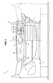
FIG. 1 is an elevation view of a front portion of an automotive vehicle according to a first embodiment of the present invention. -
FIG. 2 is a perspective view of a bumper fascia support member (herein, a left half of the figure shows a state in which a grill support member is attached). -
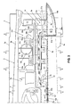
FIG. 3 is an enlarged view of a portion shown by an arrow A ofFIG. 1 . -
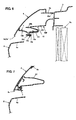
FIG. 4 is a sectional view (end face view) taken along line B-B ofFIG. 3 . -
FIG. 5 is a sectional view (end face view) taken along line C-C ofFIG. 3 . -
FIG. 6 is a sectional view (end face view) taken along line D-D ofFIG. 3 . -
FIG. 7 is a sectional view (end face view) taken along line E-E ofFIG. 3 . -
FIG. 8 is a sectional view (end face view) taken along line F-F ofFIG. 3 . -
FIG. 9 is a perspective view of the bumper fascia support member and the grill support member. -
FIG. 10 is a sectional view (end face view) taken along line G-G ofFIG. 3 . -
FIG. 11 is a sectional view (end face view) taken along line H-H ofFIG. 3 . -
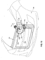
FIG. 12 is a perspective view of a front portion of an automotive vehicle according to a second embodiment of the present invention. -
FIG. 13 is a sectional view (end face view) taken along line J-J ofFIG. 12 . -
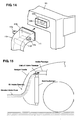
FIG. 14 is a perspective view of a duct and a shroud member, which are separated from each other at a connection portion. -
FIG. 15 is a diagram explaining a problem to be solved. - Although two embodiments are described separately, single features of one embodiment may be combined with the other embodiment.
- Hereinafter, front portion structures of an automotive vehicle according to preferred embodiments of the present invention will be described.
- As shown in
FIG. 1 , abumper 2 is provided at a front end portion of an automotive vehicle 1 according to the present embodiment. An engine room where an engine is disposed is provided behind abumper 2, and a radiator Ra to cool a cooling water of the engine is provided at a front portion of the engine room. The radiator Ra is fixed to a vehicle body via arectangular shroud member 3. An inlet Eni of an intake passage En of the engine is provided above and in back of the radiator Ra. - The
bumper 2 comprises abumper fascia 4 which forms a design face of the front end portion of the vehicle body and a bumper-fascia support member 5 which is provided so as to face to a back face of thebumper fascia 4 and attached to anupper portion 3a of theshroud member 3 to support thebumper fascia 4 from behind. - An
air intake opening 4a which introduces outside air therein is formed at a specified portion of thebumper fascia 4 which substantially faces to the heat exchanger Ra. Theair intake opening 4a is formed so as to extend substantially outward in a vehicle width direction beyond the heat exchanger Ra in an elevation view of the vehicle. - At the
air intake opening 4a is preferably provided agrill member 6 which decorates thisopening 4a (covers a bumper reinforcement R which extends in the vehicle width direction behind theopening 4a). Further, at theair intake opening 4a of thebumper fascia 4 is preferably provided a rectangulargrill support member 7 to attach thegrill member 6 to the bumper-fascia support member 5. Thegrill support member 7 has preferably substantially the same shape as the above-describedair intake opening 4a. Herein, theair intake opening 4a is preferably divided by thegrill member 6 into two parts; an upper part (a portion between an upper edge portion of theopening 4a and an upper edge portion of the grill member 6) and a lower part (a portion between a lower edge portion of theopening 4a and a lower edge portion of the grill member 6). Herein, these will be referred to as an "upper-side portion" and a "lower-side portion" of theair intake opening 4a at need. - The bumper-
fascia support member 5 has preferably substantially the same width and height as theupper portion 3a of theshroud member 3, and thismember 5 is attached to theupper portion 3a of theshroud 3 and the like. - The
shroud member 3, which is preferably made from resin, is preferably fixed to a vehicle-body structure member, such as right and left side frames (not illustrated), and theupper portion 3a of themember 3 has openingportions side opening portion 3b guides the air which has been introduced from the upper-side portion of theair intake opening 4a of thebumper fascia 4 to a portion of the engine room behind theshroud member 3. The right-side opening portion 3b guides the air which has been introduced from the upper-side portion of theair intake opening 4a of thebumper fascia 4 to the inlet Eni of the engine intake passage En. Behind the right-side opening portion 3b is preferably provided a cylindricalconnection flange portion 3e which extends rearward, and the inlet Eni of the engine intake passage En is connected to theflange portion 3e (seeFIG. 5 ). - Herein, according to the present embodiment, the
duct 10 which guides the air, which has been introduced from the upper-side portion of theair intake opening 4a of thebumper fascia 4, to the portion of the engine room behind theshroud member 3 and the inlet Eni of the engine intake passage En respectively is preferably comprised of thebumper fascia 4, bumper-fascia support member 5, andshroud member 3. - Hereinafter, the structure of these members constituting the
duct 10 will be described specifically. The bumper-fascia support member 5, as shown inFIG. 2 , preferably comprises a fascia-central-portionsupport face portion 5a, fascia-upper-edge-portion support portions grill fixing portions member fixing portions lower duct portions support face portion 5a is located at a central portion in the vehicle width direction so as to extend substantially rearward and upward along an inner face of thebumper fascia 4. The fascia-upper-edge-portion support portions support face portion 5a and support the upper edge portion of thebumper fascia 4. Thegrill fixing portions support face portion 5a and anupper side portion 7a of thegrill support member 7 is preferably fixed to thisgrill fixing portions member fixing portions portion support portions portions upper portion 3a of theshroud member 3. Thelower duct portions support face portion 5a respectively so as to form a lower portion of theduct 10. An upper portion of theduct 10 is preferably formed by a face portion of thebumper fascia 4 which is located above thelower duct portions - The
lower duct portion 5e, as shown inFIG. 3 , comprises preferably an inwardside face portion 50a which is located substantially beside the fascia-central-portionsupport face portion 5a, abottom face portion 50b which extends laterally from a lower end of the inwardside face portion 50a, an outwardside face portion 50c which is provided between an outward end of thebottom face portion 50b and the fascia-upper-edge-portion support portions 5b, arear face portion 50d, and pluraloutlet opening portions rear face portion 50d which is located in front of theopening portion 3b of theshroud member 3. Thus, thelower duct portion 5e has abody portion 50f which is of a substantially box shape with its front side and upper side opening. - The
body portion 50f is, as apparent fromFIG. 3 , positioned above theair intake opening 4a, and below an outward end of thebody portion 50f is provided a gutter-shapedguide portion 50g which projects forward to guide the air to thebody portion 50f. - As shown in
FIG. 4 , theguide portion 50g comprises abottom face portion 51a which is provided substantially continuously to an air-guide face portion 6a extending horizontally along the upper edge portion of thegrill member 6, and arear face portion 51c which rises from a rear end of thebottom face portion 51a to a position near a front end of thebottom face portion 50b of thebody portion 50f. Further, as apparent fromFIG. 3 , at both sides of thebottom face portion 51a are providedside face portions guide portion 50g. - A lower portion of the
guide portion 50g is located at a position below thebottom face portion 50b so as to be exposed to a specified portion of the upper-side portion of theair intake opening 4a which is positioned substantially outside of the heat exchanger Ra. Herein, the lower portion of theguide portion 50g constitutes aninlet portion 10a of theduct 10 together with anupper edge portion 4a' of theair intake opening 4a of thebumper fascia 4. Herein, as apparent fromFIGS. 1 ,2 and others, thebumper fascia 4 and the bumper-fascia support member 5 are formed substantially symmetrically, so that theinlet portion 10a comprises two inlets which are disposed away from each other so as to be exposed to specified portions of the upper-side portion of theair intake opening 4a which are located at both sides of the radiator Ra. - Further, as shown in
FIGS. 3 and4 , at thelower duct portion 5e is provided aneaves portion 50h which projects forward substantially horizontally from an upper end of therear face portion 51c of theguide portion 50g. Theeaves portion 50h traps a water portion, such as rainwater, which comes from theinlet portion 10a of theduct 10 via theguide portion 50g and makes the water portion drop therefrom, thereby preventing the water portion from coming down to the downstream of theeaves portion 50h (toward the inlet Eni of the engine intake passage; to the upper portion inFIGS. 3 and4 ). Moreover, theeaves portion 50h prevents the water, which has come in from theinlet portion 10a of theduct 10 when the road is flooded, from flowing down to the downstream of theeaves portion 50h (the same as above). Herein, theeaves portion 50h is provided so as to extend toward the central portion of the vehicle over an almost whole width of thelower duct portion 5e. - Further, as shown in
FIGS. 3 ,5 and6 , at thelower duct portion 5e is preferably provided aguide portion 50i which projects obliquely forward and downward from a rear end portion of theeaves portion 50h of theguide portion 50g. Theguide portion 50i is located on the central side of theguide portion 50g in such a manner that its central portion is positioned at a lower level so as to guide the water portion dropped from theeaves portion 50h and the water coming in from theinlet portion 10a of theduct 10 toward adrain portion 10d of aguide connection portion 52, which will be described below. - As apparent from
FIGS. 1 and2 , theupper side portion 7a of thegrill support member 7 extends in the vehicle width direction along the rear face of the upper edge portion of theair intake opening 4a of thebumper fascia 4. Further, as shown inFIG. 4 , a horizontallateral face portion 70a is formed above theguide portion 50g of thelower duct portion 50e. A rear end of thelateral face portion 70a is located substantially at a position of the front end of theeaves portion 50h in the longitudinal direction, so that the air coming in from theinlet portion 10a of theduct 10 can be made flow surely below theeaves portion 50h. Consequently, the water portion, such as raindrops, which is contained in the air can be shut out (trapped) surely by theeaves portion 50h. - Further, as apparent from
FIGS. 5 and6 , aprojection wall portion 70b is preferably provided at a specified portion of theupper side portion 7a of thegrill support member 7 which is located inward from theguide portion 50g of thelower duct portion 5e. Theprojection wall portion 70b projects obliquely rearward and downward from the inner face position of thebumper fascia 4, and a tip end (rear end portion) of theprojection wall portion 70b is located near the front end portion of theguide portion 50i. Thereby, a gap between the inner face of thebumper fascia 4 and the front end portion of theguide portion 50i is covered substantially, so that the water contained in the air which has come in from the specified portion of theair intake opening 4a which is located inward from the guide portion or the water supplied from below the vehicle body can be properly prevented from flowing into the space inside theduct 10. - Moreover, as apparent from
FIGS. 3 and7 , theguide connection portion 52 is preferably provided below the fascia-central-portionsupport face portion 5a of the bumper-fascia support member 5. Theguide connection portion 52 has a cross section with its front side opening so as to be continuous to therespective eaves portions portions lower duct portions guide connection portion 52 and the both-side guide portions inlet portions duct 10 and lower than the inlet Eni of the intake passage En. Theseguide connection portion 52 andguide portions connection portion 10c" at need). - A central portion 52' of the
guide connection portion 52 is configured, as apparent fromFIG. 3 , such that itsbottom face portion 52a is located at a lower level than that of the right and left portions of theguide connection portion 52. As apparent fromFIGS. 8 ,10 and 11 , between afront end 52a' of thebottom face portion 52a of the central portion 52' and anupper edge portion 4a' (a lower end portion of the grill support member 7) of theair intake opening 4a of thebumper fascia 4 is preferably provided agap 10d having a specified amount of distance in the longitudinal direction (thegap 10d corresponds to a drain portion in the claims; hereinafter, referred to as a "drain portion 10d"). The water which flows to the central portion 52' of theguide connection portion 52 from the both sides is drained out of thedrain portion 10d to the outside of theduct 10. Herein, thisgap 10d is formed substantially over a whole width of the central portion 52', so that the relativelylarge drain portion 10d can be made easily. The reason thebottom face portion 52a of the central portion 52' is located at the lower level than that of the right and left portions of theguide connection portion 52 is to prepare for a case in which the water could be collected and stored temporally even when the large amount of water flows in from the both sides at one time. - The bumper-
fascia support member 5 preferably comprises, as shown inFIG. 9 , lower ductfront portion members lower duct portion 5e, specifically, theguide portion 50g,eaves portion 50h,guide portion 50i and afront potion 50c' of the outwardside face portion 50c, and abody member 13 which forms other parts. Herein,FIG. 9 illustrates thegrill support member 7 as well as the bumper-fascia support member 5. - These
members front portion members body member 13 is made of. This is to improve a shock absorption function and to prevent theshroud member 3 from being broken against the vehicle frontal collision or the like. That is, while theguide portion 50g of thelower duct portion 5e is formed so as to project forward having thebottom face portion 51a and theside face portions body member 13. - The
body member 13 hasopenings 13d...13d to reduce the rigidity if the central portion of the bumper-fascia support member 5 at lower both-side portions of the fasciasupport face portion 5a. - Next, fixing and supporting among these
members bumper fascia 4, andgrill support member 7 will be described. - At first, the fixing between the
body member 13 and the lower ductfront portion members FIG. 9 . A substantiallyrectangular frame portion 13a is formed at thebody member 13 at a location in front of thebottom face portion 50b of thelower duct portion 5e. Theguide portion 50i of the lower ductfront portion member 11 is placed on thisframe portion 13a from above.Boss portions bottom face portion 50b of thelower duct portion 5e of the body member andattachment piece portions eaves portion 50h of the lower ductfront portion member 11 are overlapped substantially longitudinally, and these overlapped portions are fixed with screws, not illustrated (seeFIGS. 2 and3 ).Attachment portions frame portion 13a of thebody member 13 andattachment piece portions guide portion 50i of the lower ductfront portion member 11 are fixed with screws. - Further, as shown in
FIG. 10 ,attachment portions emblem portion 13d which is provided at a central portion of the fasciasupport face portion 5a of thebody member 13 andboss portions bumper fascia 4 are fixed with screws. - The fascia
support face portion 5a of thebody member 13 has acontact portion 13f to contact the central portion of thebumper fascia 4 as shown inFIG. 11 . - Moreover, as shown in
FIG. 6 , aboss portion 70d which is formed at a rear end portion of the above-describedprojection wall portion 70b of thegrill support member 7 and anattachment portion 13e (seeFIG. 9 ) which is provided at the front side portion of theframe portion 13a of thebody member 13 are fixed with screws. - Hereinafter, the function of the present embodiment will be described.
- At first, the flow of the air which has come in through the
air intake opening 4a of thebumper fascia 4 to the inlet Eni of the engine intake passage En will be described. A part of the air coming in through theair intake opening 4a at thebumper fascia 4 is guided to the inlet Eni of the intake passage En of the engine via theduct 10 which has theinlet portion 10a which is disposed so as to be exposed to the upper-side portion of theair intake opening 4a of thebumper fascia 4 and theoutlet portion 10b of which connects to the inlet Eni of the intake passage En of the engine, as shown by the white arrows inFIGS. 3 through 5 . - Thereby, even if the water coming in the vehicle front body through the
air intake opening 4a rises up to the height of the inlet Eni of the engine intake passage En in the space behind theinlet portion 10a of theduct 10 and before the heat exchanger Ra, the water can be prevented from coming into theduct 10 as long as the water height on the flooded road is lower than that of theinlet portion 10a of theduct 10. Thus, the risk of the water coming into the inlet Eni of the intake passage En of the engine, thereby causing damage to the engine, can be reduced properly. - Further, the
air intake opening 4a is formed so as to extend substantially outward in the vehicle width direction beyond the heat exchanger Ra in the elevation view of the vehicle, and theinlet portion 10a of theduct 10 is disposed so as to be exposed to the portion of theair intake opening 4a which is positioned outside of the heat exchanger Ra. Thereby, theinlet portion 10a of theduct 10 does not exist in front of the heat exchanger Ra. Accordingly, even if theinlet portion 10a of theduct 10 is disposed so as to be exposed to theair intake opening 4a, the air introduction toward the heat exchanger Ra is not prevented. - Herein, the water height on the flooded road may change, so that a case in which the water height rises up above the
inlet portion 10a of theduct 10 temporally should be anticipated. Further, if the water comes into theduct 10, the amount of air supplied to the engine may be reduced. Some countermeasures against this should be necessary as well. - According to the present embodiment, the
inlet portion 10a of theduct 10 comprises two inlets which are disposed away from each other in the vehicle width direction, and there is provided theconnection portion 10c which connects downstream portions of theinlets 10a and extends in the vehicle width direction at the positioned which is above theinlets 10a of theduct 10 and below the inlet Eni of the intake passage En of the engine. Thereby, an enlarged space is ensured by theconnection portion 10c of theduct 10 which extends in the vehicle width direction at a middle level between theinlet portion 10a of theduct 10 and the inlet Eni of the engine intake passage En. Accordingly, even in case, as shown by dark arrows inFIGS. 3 and4 , the height of the water on the flooded road increases temporarily up above theinlet portion 10a of theduct 10 and consequently the water comes in through theinlet portion 10a of theduct 10, the water flows into theconnection portion 10c, so that theduct 10 can be properly prevented from being filled with the water. As a result, the water coming into theduct 10 can be prevented properly from reaching the inlet Eni of the engine intake passage En, and the proper air flow to the inlet Eni of the engine can be ensured. Moreover, since theplural inlets 10a of theduct 10 are provided, even when the water comes in through one of theinlets 10a, the necessary amount of air for the engine can be effectively ensured. Further, since theeaves portion 50h is provided, the water coming in through theinlet portion 10a can be prevented properly from flowing to the downstream (upper) side of theeaves portion 50h, thereby preventing the water reaching the inlet Eni of the engine intake passage En more properly. - Moreover, since the
drain portion 10d is provided at theconnection portion 10c of theduct 10, the water coming into theduct 10 through theinlet portion 10a is discharged from thedrain portion 10d as shown by dark arrows inFIGS. 3 and8 even in the case the water comes into theduct 10. Accordingly, preventing the water from reaching the inlet Eni of the engine intake duct En can be improved. - Further, since the
duct 10 includes thebumper fascia 4, theduct 10 can be formed properly by using a member which is generally provided at the automotive vehicle. Also, since theduct 10 includes thefascia support member 5 which is provided so as to face to the back face of thebumper fascia 4, theduct 10 can be provided along with thebumper fascia 4 having its increased rigidity. - The following function and advantage may be also obtained when the vehicle travels on rainy days, even not on the flooded road, according to the present embodiment.
- Since there is provided the
eaves portion 50h extending substantially horizontally, the rainwater which has come in from theair intake opening 4a via theinlet portion 10a as shown by the dark arrows inFIGS. 3 and4 when the vehicle travels on the rainy days or the like is trapped at the lower face of theeaves portion 50h and drops. Thus, the rainwater can be prevented from coming down to the downstream (upward) of theeaves portion 50h. - Further, the
guide portions 50i are provided at the right and lefteaves portions 50h, and theguide connection portion 52 to drain the water is provided so as to extend in the vehicle width direction between these both guideportions eaves portion 50h is guided to theguide connection portion 52 at the central portion, and then is drained to the outside from thedrain portion 10c of theguide connection portion 52. - The following advantage may be also obtained at the vehicle frontal collision or the like according to the present embodiment. That is, an impact load acts on the
bumper 2 of the vehicle 1 from the front obliquely at the vehicle frontal collision or the like, and this impact load is inputted to the bumper-fascia support member 5 via the low-rigidity bumper fascia 4. Herein, since the lower ductfront portion members fascia support member 5 are made of the low-rigidity member, themembers - Herein, the rigidity of the bumper-
fascia support member 5 generally tends to increase with theduct 10 having a structure comprising walls, so that there is a concern that the impact load would not be absorbed properly. According to the present invention, however, the lower ductfront portion members duct 10 is formed. Further, the breakage of the lower ductfront portion members lower duct portion 5e may properly prevent thebody member 13 of the bumper-fascia support member 5 from being broken. The breakage of theshroud member 3, which is disposed behind the bumper-fascia support member 5 and theopening portion 3b of which the duct connects to, may be also prevented. - The
body member 13 has a sufficient rigidity, so that an improper deformation of thebumper fascia 4 can be prevented in its normal condition. - According to a second embodiment, as shown in
FIG. 12 , aduct 110 is made of a particular member which interconnects an upper-portion side of anopening 104a of abumper fascia 104 and anopening portion 103b of anupper side portion 103a of ashroud member 103. - The
duct 110 has, as shown inFIG. 13 as well, fixingpiece portions bumper fascia 104 at its front end portion and middle portion. The fixingpiece portions duct 110 are preferably fixed to aboss 104b which is formed at a back face of an upper edge portion of theopening 104a of thebumper fascia 104 with screws. The fixingpiece portion 110d of the lower front end of theduct 110 is preferably fixed to aboss 106a which is formed at a back face of an upper edge portion of the grill member 106 with screws. The fixingpiece portions duct 110 are preferably fixed to aboss 104c which is formed at a back face of a specified portion of thebumper fascia 104 which is located above theopening 104a with screws. - Further, as shown in
FIG. 14 , acylindrical penetration portion 103c is formed substantially at theupper side portion 103a of theshroud member 103, and anoutlet portion 110b of theduct 110 is connected to the front side of thepenetration portion 103c, while the inlet Eni of the engine intake passage En is connected to the rear side of thepenetration portion 103c. Thus, theoutlet portion 110b of theduct 110 connects to the inlet Eni of the intake passage En via thepenetration portion 103c. Herein, the inner diameter of theoutlet portion 110b of theduct 110 is set to be slightly greater than the outer diameter of thepenetration portion 103c, considering the forming accuracy or the like. Consequently, since there is a concern that the heat of the radiator Ra would come in through its gap, there is preferably provided asponge member 111 to prevent this at a rear end portion of theoutlet portion 110b of theduct 110. - Further,
water shutout portions inlet portion 110a from reaching theoutlet portion 110b are provided at two positions in theduct 110 near theinlet portion 110a and theoutlet portion 110b respectively. - According to the second embodiment, like the first embodiment, a part of the air coming in through the
air intake opening 104a at thebumper fascia 104 is guided to the inlet Eni of the intake passage En of the engine via theduct 110 which has theinlet portion 110a which is disposed so as to be exposed to the upper-side portion of theair intake opening 104a of thebumper fascia 104 and theoutlet portion 110b of which connects to the inlet Eni of the intake passage En of the engine. - Thereby, even if the water coming in the vehicle front body through the
air intake opening 104a rises up to the height of the inlet Eni of the engine intake passage En in the space behind theinlet portion 110a of theduct 110 and before the heat exchanger Ra, the water can be prevented from coming into theduct 110 as long as the water height on the flooded road is lower than that of theinlet portion 110a of theduct 110. Thus, the risk of the water coming into the inlet Eni of the intake passage En of the engine, thereby causing damage to the engine, can be reduced properly. - Moreover, according to the second embodiment, the above-described advantages can be obtained by adding the duct with a simple structure even in a case in which the fascia support member like the first embodiment is not provided, or a fascia support member having a different structure.
- The present invention should not be limited to the above-descried embodiments, and any other modifications and improvements may be applied within the scope the present invention, as defined by the appended claims.
Claims (15)
- An engine intake passage structure of a front vehicle body, comprising:an intake passage (En) of an engine, an inlet (Eni) of which is disposed above a heat exchanger (Ra) which is provided at a front portion of a vehicle body;an air intake opening (4a; 104a) to introduce outside air therein, the air intake opening (4a; 104a) being formed at a bumper fascia (4; 104) which forms an outer face of the front portion of the vehicle body; anda duct (10; 110) to guide the outside air, an inlet portion (10a; 110a) of which is disposed so as to be exposed to an upper-side portion of the air intake opening (4a; 104a) and an outlet portion (10b; 110b) of which connects to the inlet (Eni) of the intake passage (En) of the engine.
- The engine intake passage structure of a front vehicle body of claim 1, wherein said intake opening (4a; 104a) is formed at a specified portion of the bumper fascia (4; 104), said specified portion facing to the heat exchanger (Ra).
- The engine intake passage structure of a front vehicle body of any one of claims 1 or 2, wherein said air intake opening (4a; 104a) is formed so as to extend substantially outward in a vehicle width direction beyond the heat exchanger (Ra) in an elevation view of a vehicle (1), and/or said inlet portion (10a; 110a) of the duct (10; 110) is disposed so as to be exposed to a portion of the air intake opening (4a; 104a) which is positioned substantially outside of the heat exchanger (Ra).
- The engine intake passage structure of a front vehicle body of any one or more of the preceding claims, wherein said inlet portion (10a; 110a) of the duct (10) comprises a plurality of inlets (10a...10a) which are disposed away from each other in a vehicle width direction, and there is provided a connection portion (10c) which connects downstream portions of the plural inlets (10a...10a) and extends in the vehicle width direction at a position which is above the inlets (10a...10a) of the duct (10) and below said inlet (Eni) of the intake passage (En) of the engine.
- The engine intake passage structure of a front vehicle body of claim 4, wherein a drain portion (10d) is provided at said connection portion (10c) of the duct (10).
- The engine intake passage structure of a front vehicle body of any one or more of the preceding claims, wherein said duct (10) includes the bumper fascia (4) and a member (5) which is provided so as to face to a back face of the bumper fascia (4), said member being preferably formed by or being integral with a bumper-fascia support member (5).
- The engine intake passage structure of a front vehicle body of any one or more of the preceding claims, wherein a lower duct portion (5e) of said duct (10; 110) comprises an eaves portion (50h) which can trap water coming from the inlet portion (10a; 110a) of said duct (10; 110).
- The engine intake passage structure of a front vehicle body of any one or more of the preceding claims, wherein said eaves portion (50h) projects substantially horizontally forward from said bumper-fascia support member (5).
- The engine intake passage structure of a front vehicle body of any one or more of the preceding claims, wherein a gap is formed between a front end (52a') of a bottom face portion (52a) of a central portion (52') of said bumper-fascia support member (5) and said bumper fascia (4), said gap serving as the drain portion (10d) to separate water from the sucked air.
- The engine intake passage structure of a front vehicle body of any one or more of the preceding claims, wherein said bumper-fascia support member (5) comprises a body member (13) and a pair of lower duct front portion members (11, 11) which form a front portion of a lower duct portion (5e).
- The engine intake passage structure of a front vehicle body of any one or more of the preceding claim 10, wherein said body member (13) and said pair of lower duct front portion members (11, 11) are made from resin, wherein said pair of lower duct front portion members (11, 11) are preferably made from a material which has a lower rigidity than a material from which the body member (13) is made.
- A method of providing an engine intake passage structure of a front vehicle body, comprising the steps of:providing an inlet (Eni) of an intake passage (En) of an engine above a heat exchanger (Ra) which is provided at a front portion of a vehicle body;forming an air intake opening (4a; 104a) to introduce outside air therein at a bumper fascia (4; 104) which forms an outer face of the front portion of the vehicle body; andproviding a duct (10; 110) to guide the outside air, an inlet portion (10a; 110a) of which is disposed so as to be exposed to an upper-side portion of the air intake opening (4a; 104a) and an outlet portion (10b; 110b) of which connects to the inlet (Eni) of the intake passage (En) of the engine.
- The method of providing an engine intake passage structure of a front vehicle body of claim 12, further comprising the step of forming said intake opening (4a; 104a) at a specified portion of the bumper fascia (4; 104), said specified portion facing to the heat exchanger (Ra).
- The method of providing an engine intake passage structure of a front vehicle body of any one of claims 12 or 13, further comprising the steps of forming said air intake opening (4a; 104a) so as to extend substantially outward in a vehicle width direction beyond the heat exchanger (Ra) in an elevation view of a vehicle (1), and/or disposing said inlet portion (10a; 110a) of the duct (10; 110) so as to be exposed to a portion of the air intake opening (4a; 104a) which is positioned substantially outside of the heat exchanger (Ra).
- The method of providing an engine intake passage structure of a front vehicle body of any one or more of the preceding claims 12 to 14, further comprising the steps of providing said inlet portion (10a; 110a) of the duct (10) with a plurality of inlets (10a...10a) which are disposed away from each other in a vehicle width direction, and providing a connection portion (10c) which connects downstream portions of the plural inlets (10a...10a) and extends in the vehicle width direction at a position which is above the inlets (10a...10a) of the duct (10) and below said inlet (Eni) of the intake passage (En) of the engine.
Applications Claiming Priority (1)
| Application Number | Priority Date | Filing Date | Title |
|---|---|---|---|
| JP2008204070A JP4730411B2 (en) | 2008-08-07 | 2008-08-07 | Engine intake passage structure at the front of the vehicle body |
Publications (3)
| Publication Number | Publication Date |
|---|---|
| EP2169210A2 true EP2169210A2 (en) | 2010-03-31 |
| EP2169210A3 EP2169210A3 (en) | 2010-05-12 |
| EP2169210B1 EP2169210B1 (en) | 2012-06-06 |
Family
ID=41395960
Family Applications (1)
| Application Number | Title | Priority Date | Filing Date |
|---|---|---|---|
| EP09010006A Not-in-force EP2169210B1 (en) | 2008-08-07 | 2009-08-03 | Engine intake passage structure of front vehicle body and method of providing the same |
Country Status (4)
| Country | Link |
|---|---|
| US (1) | US8474558B2 (en) |
| EP (1) | EP2169210B1 (en) |
| JP (1) | JP4730411B2 (en) |
| CN (1) | CN101643023B (en) |
Cited By (3)
| Publication number | Priority date | Publication date | Assignee | Title |
|---|---|---|---|---|
| CN105612074A (en) * | 2013-10-07 | 2016-05-25 | 丰田自动车株式会社 | Mobile body in which fuel cell is mounted |
| DE102016101703A1 (en) * | 2016-02-01 | 2017-08-03 | Dr. Ing. H.C. F. Porsche Aktiengesellschaft | Drive system of a vehicle |
| CN109707542A (en) * | 2017-10-26 | 2019-05-03 | 丰田自动车株式会社 | Ventilation pipe |
Families Citing this family (34)
| Publication number | Priority date | Publication date | Assignee | Title |
|---|---|---|---|---|
| JP4730411B2 (en) * | 2008-08-07 | 2011-07-20 | マツダ株式会社 | Engine intake passage structure at the front of the vehicle body |
| DE102009031746A1 (en) * | 2009-07-06 | 2011-01-13 | GM Global Technology Operations, Inc., Detroit | Cooling air guiding device for a motor vehicle |
| GB201004451D0 (en) * | 2010-03-17 | 2010-05-05 | Trysome Ltd | Air intake structure |
| US8540043B2 (en) * | 2010-08-30 | 2013-09-24 | Honda Motor Co., Ltd. | Over bulkhead air intake for reduced snow ingestion |
| US8528679B2 (en) * | 2010-11-09 | 2013-09-10 | Honda Motor Co., Ltd. | Air separating intake scoop for air intake system |
| US8746386B2 (en) | 2011-01-13 | 2014-06-10 | Toyota Motor Engineering & Manufacturing North America, Inc. | Vehicle performance enhancing apparatus |
| JP5417350B2 (en) * | 2011-01-25 | 2014-02-12 | 本田技研工業株式会社 | Body front structure |
| DE102013006245B4 (en) * | 2013-04-11 | 2016-12-29 | Volkswagen Aktiengesellschaft | Air duct with water separation device in the front of a motor vehicle |
| KR101509703B1 (en) * | 2013-10-10 | 2015-04-07 | 현대자동차 주식회사 | Air cleaner for vehicle |
| DE102013223105A1 (en) * | 2013-11-13 | 2015-05-13 | Röchling Automotive SE & Co. KG | In vehicle carrier integrated gas, especially air guiding device |
| WO2015080688A1 (en) * | 2013-11-29 | 2015-06-04 | Heksagon Muhendislik Ve Tasarim Anonim Sirketi | A combustion system |
| JP6048388B2 (en) * | 2013-12-17 | 2016-12-21 | マツダ株式会社 | Automotive front structure |
| JP6048389B2 (en) * | 2013-12-17 | 2016-12-21 | マツダ株式会社 | Automotive front structure |
| US9211791B2 (en) | 2014-03-31 | 2015-12-15 | Honda Motor Co., Ltd. | Automobile over-bulkhead air intake system |
| FR3020322B1 (en) * | 2014-04-29 | 2016-05-27 | Valeo Systemes Thermiques | AIR GUIDE FOR MOTOR VEHICLE |
| JP6413782B2 (en) * | 2015-01-19 | 2018-10-31 | スズキ株式会社 | Engine intake system |
| US9487251B2 (en) * | 2015-03-17 | 2016-11-08 | GM Global Technology Operations LLC | Vehicle having an integrated air curtain and brake cooling duct |
| DE102015214313B4 (en) | 2015-07-29 | 2017-12-28 | Bayerische Motoren Werke Aktiengesellschaft | Motor vehicle with an air intake system for improved water passage |
| JP6579322B2 (en) * | 2015-12-25 | 2019-09-25 | スズキ株式会社 | Intake shroud structure |
| US9982638B2 (en) * | 2016-05-10 | 2018-05-29 | Ford Global Technologies Llc | Water/snow management for air intake system to active grill system interface |
| JP6549642B2 (en) * | 2017-06-14 | 2019-07-24 | 本田技研工業株式会社 | Vehicle intake structure |
| JP6438529B1 (en) * | 2017-06-14 | 2018-12-12 | 本田技研工業株式会社 | Vehicle intake structure |
| US10308287B2 (en) * | 2017-08-14 | 2019-06-04 | GM Global Technology Operations LLC | Air inlet splash panel assembly for a vehicle |
| DE102017119829B4 (en) * | 2017-08-29 | 2022-08-04 | Dr. Ing. H.C. F. Porsche Aktiengesellschaft | Motor vehicle with air guiding means and an air duct |
| USD1023061S1 (en) | 2020-02-09 | 2024-04-16 | Velossa Tech Engineering, Inc. | Ram-air intake |
| USD1019704S1 (en) | 2020-02-09 | 2024-03-26 | Velossa Tech Engineering, Inc. | Ram-air intake |
| US12180916B2 (en) | 2020-02-09 | 2024-12-31 | Velossa Tech Engineering Inc. | Interchangeable intake manifold assemblies |
| USD1031782S1 (en) | 2020-02-09 | 2024-06-18 | Velossa Tech Engineering, Inc. | Ram-air intake |
| CN114906085B (en) * | 2021-02-07 | 2023-09-29 | 广州汽车集团股份有限公司 | A vehicle wading treatment method, device and system |
| USD994872S1 (en) * | 2021-06-11 | 2023-08-08 | Velossa Tech Engineering Inc. | RAM-air intake |
| US11655752B2 (en) | 2021-09-30 | 2023-05-23 | Ford Global Technologies, Llc | Water separator to slow water ingestion |
| US11536230B1 (en) | 2021-10-26 | 2022-12-27 | Ford Global Technologies, Llc | Charge-air cooler and water distribution device to evenly proved water to engine cylinders |
| US11698037B1 (en) | 2022-04-08 | 2023-07-11 | Ford Global Technologies, Llc | Fuel system for a vehicle and method of controlling |
| FR3138081B1 (en) * | 2022-07-19 | 2025-12-26 | Psa Automobiles Sa | Bumper frame for motor vehicle |
Citations (1)
| Publication number | Priority date | Publication date | Assignee | Title |
|---|---|---|---|---|
| JP2005343244A (en) | 2004-06-01 | 2005-12-15 | Nissan Motor Co Ltd | Outside air introduction structure at the front of the vehicle body |
Family Cites Families (34)
| Publication number | Priority date | Publication date | Assignee | Title |
|---|---|---|---|---|
| JPS5778759U (en) | 1980-10-31 | 1982-05-15 | ||
| JPS59192618A (en) * | 1983-04-15 | 1984-11-01 | Toyota Motor Corp | Suction device of internal-combustion engine |
| US4653788A (en) * | 1986-01-17 | 1987-03-31 | Fiat Auto S.P.A. | Front bumper for motor vehicles |
| GB2198801B (en) * | 1986-12-19 | 1991-02-20 | Masco Ind Inc | Locking fastener |
| US4902059A (en) * | 1988-09-19 | 1990-02-20 | Tritton Richard F | Vehicle bumper system for forming part of engine cooling assembly |
| US5054567A (en) * | 1989-06-30 | 1991-10-08 | Navistar International Transportation Corp. | Truck hood reinforcement system |
| JPH0354080A (en) * | 1989-07-21 | 1991-03-08 | Nissan Motor Co Ltd | First cross member structure for automobile |
| US4932490A (en) * | 1989-09-29 | 1990-06-12 | Navistar International Transportation Corp. | Engine air induction system with air cleaner in hood |
| US5022479A (en) * | 1990-02-16 | 1991-06-11 | Navistar International Transportation Corp. | Motor vehicle engine air intake system including moisture elimination apparatus |
| IT1239473B (en) * | 1990-04-10 | 1993-11-02 | Alfa Lancia Spa | AIR INTAKE FOR THE POWER OF A MOTOR |
| US5042603A (en) * | 1990-04-23 | 1991-08-27 | Navistar International Transportation Corp. | Engine air intake apparatus |
| JP2526659Y2 (en) | 1991-06-24 | 1997-02-19 | マツダ株式会社 | Vehicle intake duct intake structure |
| US5618323A (en) * | 1994-01-28 | 1997-04-08 | Paccar Inc | Integral cab and engine air intake system for a vehicle |
| US5660243A (en) * | 1995-02-13 | 1997-08-26 | Chrysler Corporation | Air flow, atmospheric particle, and environmental element diverter system |
| US5860685A (en) * | 1997-05-08 | 1999-01-19 | Chrysler Corporation | Fresh air duct system for a vehicle |
| FR2782480B1 (en) * | 1998-08-24 | 2000-10-20 | Solvay | DEVICE AND METHOD FOR EXHAUSTING CALORIES FROM A COMPARTMENT |
| JP3577018B2 (en) * | 2001-08-31 | 2004-10-13 | 本田技研工業株式会社 | Air intake structure around the front grill of the vehicle |
| JP4048480B2 (en) * | 2002-09-30 | 2008-02-20 | スズキ株式会社 | Automobile grill with intercooler structure |
| US6945576B1 (en) * | 2004-04-23 | 2005-09-20 | General Motors Corporation | Multifunctional bumper assembly |
| US8201651B2 (en) * | 2004-07-12 | 2012-06-19 | Honda Motor Co., Ltd. | Automobile over-bulkhead air intake system |
| US7234555B2 (en) * | 2004-07-12 | 2007-06-26 | Honda Motor Co., Ltd. | Secondary path automobile air intake system |
| US7237635B2 (en) * | 2004-07-12 | 2007-07-03 | Honda Motor Co., Ltd. | Automobile over-bulkhead air intake system |
| US6966293B1 (en) * | 2004-08-19 | 2005-11-22 | Kevin Patillo | Fan induction blower box |
| DE102004045270A1 (en) | 2004-09-17 | 2006-03-23 | Bayerische Motoren Werke Ag | Arrangement of an air filter housing for an internal combustion engine in the engine compartment of a motor vehicle |
| JP4563869B2 (en) * | 2005-05-25 | 2010-10-13 | 本田技研工業株式会社 | Automobile intake structure |
| DE102005033659B4 (en) | 2005-07-19 | 2007-12-27 | Dr.Ing.H.C. F. Porsche Ag | Drive unit for a motor vehicle |
| JP5056041B2 (en) * | 2007-02-08 | 2012-10-24 | マツダ株式会社 | Automotive bumper structure |
| DE102007015863A1 (en) | 2007-04-02 | 2008-10-09 | GM Global Technology Operations, Inc., Detroit | Air intake device for supplying fresh air to engine in motor vehicle, has snorkel arranged upstream on filter housing along air flow direction and run over hollow bumper cross beam of motor vehicle |
| US8100209B2 (en) * | 2008-03-31 | 2012-01-24 | Honda Motor Co., Ltd. | Front bulkhead cover and air flow system |
| JP4730411B2 (en) * | 2008-08-07 | 2011-07-20 | マツダ株式会社 | Engine intake passage structure at the front of the vehicle body |
| US8011465B2 (en) * | 2008-11-13 | 2011-09-06 | International Truck Intellectual Property Company, Llc | Air intake plenum for air induction channel |
| JP4712096B2 (en) * | 2009-01-07 | 2011-06-29 | 本田技研工業株式会社 | Air intake structure for automobiles |
| US8540043B2 (en) * | 2010-08-30 | 2013-09-24 | Honda Motor Co., Ltd. | Over bulkhead air intake for reduced snow ingestion |
| US8528679B2 (en) * | 2010-11-09 | 2013-09-10 | Honda Motor Co., Ltd. | Air separating intake scoop for air intake system |
-
2008
- 2008-08-07 JP JP2008204070A patent/JP4730411B2/en not_active Expired - Fee Related
-
2009
- 2009-07-16 US US12/504,359 patent/US8474558B2/en not_active Expired - Fee Related
- 2009-08-03 EP EP09010006A patent/EP2169210B1/en not_active Not-in-force
- 2009-08-07 CN CN200910165250.XA patent/CN101643023B/en not_active Expired - Fee Related
Patent Citations (1)
| Publication number | Priority date | Publication date | Assignee | Title |
|---|---|---|---|---|
| JP2005343244A (en) | 2004-06-01 | 2005-12-15 | Nissan Motor Co Ltd | Outside air introduction structure at the front of the vehicle body |
Cited By (7)
| Publication number | Priority date | Publication date | Assignee | Title |
|---|---|---|---|---|
| CN105612074A (en) * | 2013-10-07 | 2016-05-25 | 丰田自动车株式会社 | Mobile body in which fuel cell is mounted |
| CN105612074B (en) * | 2013-10-07 | 2019-01-22 | 丰田自动车株式会社 | Mobile bodies equipped with fuel cells |
| DE102016101703A1 (en) * | 2016-02-01 | 2017-08-03 | Dr. Ing. H.C. F. Porsche Aktiengesellschaft | Drive system of a vehicle |
| DE102016101703B4 (en) | 2016-02-01 | 2023-03-23 | Dr. Ing. H.C. F. Porsche Aktiengesellschaft | drive system of a vehicle |
| CN109707542A (en) * | 2017-10-26 | 2019-05-03 | 丰田自动车株式会社 | Ventilation pipe |
| CN109707542B (en) * | 2017-10-26 | 2021-10-19 | 丰田自动车株式会社 | ventilation duct |
| US11181082B2 (en) | 2017-10-26 | 2021-11-23 | Toyota Jidosha Kabushiki Kaisha | Ventilation duct |
Also Published As
| Publication number | Publication date |
|---|---|
| JP2010036797A (en) | 2010-02-18 |
| US20100032220A1 (en) | 2010-02-11 |
| US8474558B2 (en) | 2013-07-02 |
| EP2169210A3 (en) | 2010-05-12 |
| EP2169210B1 (en) | 2012-06-06 |
| JP4730411B2 (en) | 2011-07-20 |
| CN101643023B (en) | 2014-03-05 |
| CN101643023A (en) | 2010-02-10 |
Similar Documents
| Publication | Publication Date | Title |
|---|---|---|
| EP2169210A2 (en) | Engine intake passage structure of front vehicle body and method of providing the same | |
| US7717204B2 (en) | Bumper structure of automotive vehicle | |
| US6322440B1 (en) | Outside air intake structure | |
| JP5034639B2 (en) | Automotive front structure | |
| JP2008247122A (en) | Body front structure | |
| JP2005297888A (en) | Auto body front structure | |
| EP2824001B1 (en) | Air guide structure | |
| JP2575909B2 (en) | Automotive air box structure | |
| JP2015116888A (en) | Front part structure of vehicle | |
| JP6979260B2 (en) | Vehicle structure | |
| JPH11129935A (en) | Vehicle front-end module structure | |
| JP6699186B2 (en) | Radiator support | |
| JP4403699B2 (en) | Front body structure of automobile | |
| EP1775200B1 (en) | Front construction of motor vehicle | |
| JP6308269B2 (en) | Vehicle cowl structure | |
| JP7198798B2 (en) | vehicle front structure | |
| JP2010083217A (en) | Structure for arranging heat exchanger of vehicle front body part | |
| JP2004249816A (en) | Body front structure | |
| JP4937778B2 (en) | Automotive front structure | |
| EP4431328A1 (en) | Intake duct | |
| JP4435626B2 (en) | Vehicle intake structure | |
| JP2025187345A (en) | Cowl cover | |
| CN118163868A (en) | Front structure | |
| JP6308272B2 (en) | Vehicle cowl structure | |
| JP6308271B2 (en) | Vehicle cowl structure |
Legal Events
| Date | Code | Title | Description |
|---|---|---|---|
| PUAI | Public reference made under article 153(3) epc to a published international application that has entered the european phase |
Free format text: ORIGINAL CODE: 0009012 |
|
| AK | Designated contracting states |
Kind code of ref document: A2 Designated state(s): AT BE BG CH CY CZ DE DK EE ES FI FR GB GR HR HU IE IS IT LI LT LU LV MC MK MT NL NO PL PT RO SE SI SK SM TR |
|
| AX | Request for extension of the european patent |
Extension state: AL BA RS |
|
| PUAL | Search report despatched |
Free format text: ORIGINAL CODE: 0009013 |
|
| AK | Designated contracting states |
Kind code of ref document: A3 Designated state(s): AT BE BG CH CY CZ DE DK EE ES FI FR GB GR HR HU IE IS IT LI LT LU LV MC MK MT NL NO PL PT RO SE SI SK SM TR |
|
| AX | Request for extension of the european patent |
Extension state: AL BA RS |
|
| 17P | Request for examination filed |
Effective date: 20101111 |
|
| RIC1 | Information provided on ipc code assigned before grant |
Ipc: F02M 35/10 20060101AFI20110630BHEP Ipc: F02M 35/16 20060101ALI20110630BHEP |
|
| GRAP | Despatch of communication of intention to grant a patent |
Free format text: ORIGINAL CODE: EPIDOSNIGR1 |
|
| GRAS | Grant fee paid |
Free format text: ORIGINAL CODE: EPIDOSNIGR3 |
|
| GRAA | (expected) grant |
Free format text: ORIGINAL CODE: 0009210 |
|
| AK | Designated contracting states |
Kind code of ref document: B1 Designated state(s): AT BE BG CH CY CZ DE DK EE ES FI FR GB GR HR HU IE IS IT LI LT LU LV MC MK MT NL NO PL PT RO SE SI SK SM TR |
|
| REG | Reference to a national code |
Ref country code: GB Ref legal event code: FG4D |
|
| REG | Reference to a national code |
Ref country code: AT Ref legal event code: REF Ref document number: 561163 Country of ref document: AT Kind code of ref document: T Effective date: 20120615 Ref country code: CH Ref legal event code: EP |
|
| REG | Reference to a national code |
Ref country code: IE Ref legal event code: FG4D |
|
| REG | Reference to a national code |
Ref country code: DE Ref legal event code: R096 Ref document number: 602009007410 Country of ref document: DE Effective date: 20120802 |
|
| REG | Reference to a national code |
Ref country code: NL Ref legal event code: VDEP Effective date: 20120606 |
|
| PG25 | Lapsed in a contracting state [announced via postgrant information from national office to epo] |
Ref country code: NO Free format text: LAPSE BECAUSE OF FAILURE TO SUBMIT A TRANSLATION OF THE DESCRIPTION OR TO PAY THE FEE WITHIN THE PRESCRIBED TIME-LIMIT Effective date: 20120906 Ref country code: SE Free format text: LAPSE BECAUSE OF FAILURE TO SUBMIT A TRANSLATION OF THE DESCRIPTION OR TO PAY THE FEE WITHIN THE PRESCRIBED TIME-LIMIT Effective date: 20120606 Ref country code: CY Free format text: LAPSE BECAUSE OF FAILURE TO SUBMIT A TRANSLATION OF THE DESCRIPTION OR TO PAY THE FEE WITHIN THE PRESCRIBED TIME-LIMIT Effective date: 20120606 Ref country code: FI Free format text: LAPSE BECAUSE OF FAILURE TO SUBMIT A TRANSLATION OF THE DESCRIPTION OR TO PAY THE FEE WITHIN THE PRESCRIBED TIME-LIMIT Effective date: 20120606 Ref country code: LT Free format text: LAPSE BECAUSE OF FAILURE TO SUBMIT A TRANSLATION OF THE DESCRIPTION OR TO PAY THE FEE WITHIN THE PRESCRIBED TIME-LIMIT Effective date: 20120606 |
|
| REG | Reference to a national code |
Ref country code: AT Ref legal event code: MK05 Ref document number: 561163 Country of ref document: AT Kind code of ref document: T Effective date: 20120606 |
|
| REG | Reference to a national code |
Ref country code: LT Ref legal event code: MG4D Effective date: 20120606 |
|
| PG25 | Lapsed in a contracting state [announced via postgrant information from national office to epo] |
Ref country code: SI Free format text: LAPSE BECAUSE OF FAILURE TO SUBMIT A TRANSLATION OF THE DESCRIPTION OR TO PAY THE FEE WITHIN THE PRESCRIBED TIME-LIMIT Effective date: 20120606 Ref country code: GR Free format text: LAPSE BECAUSE OF FAILURE TO SUBMIT A TRANSLATION OF THE DESCRIPTION OR TO PAY THE FEE WITHIN THE PRESCRIBED TIME-LIMIT Effective date: 20120907 Ref country code: HR Free format text: LAPSE BECAUSE OF FAILURE TO SUBMIT A TRANSLATION OF THE DESCRIPTION OR TO PAY THE FEE WITHIN THE PRESCRIBED TIME-LIMIT Effective date: 20120606 Ref country code: LV Free format text: LAPSE BECAUSE OF FAILURE TO SUBMIT A TRANSLATION OF THE DESCRIPTION OR TO PAY THE FEE WITHIN THE PRESCRIBED TIME-LIMIT Effective date: 20120606 |
|
| PG25 | Lapsed in a contracting state [announced via postgrant information from national office to epo] |
Ref country code: IS Free format text: LAPSE BECAUSE OF FAILURE TO SUBMIT A TRANSLATION OF THE DESCRIPTION OR TO PAY THE FEE WITHIN THE PRESCRIBED TIME-LIMIT Effective date: 20121006 Ref country code: NL Free format text: LAPSE BECAUSE OF FAILURE TO SUBMIT A TRANSLATION OF THE DESCRIPTION OR TO PAY THE FEE WITHIN THE PRESCRIBED TIME-LIMIT Effective date: 20120606 Ref country code: RO Free format text: LAPSE BECAUSE OF FAILURE TO SUBMIT A TRANSLATION OF THE DESCRIPTION OR TO PAY THE FEE WITHIN THE PRESCRIBED TIME-LIMIT Effective date: 20120606 Ref country code: AT Free format text: LAPSE BECAUSE OF FAILURE TO SUBMIT A TRANSLATION OF THE DESCRIPTION OR TO PAY THE FEE WITHIN THE PRESCRIBED TIME-LIMIT Effective date: 20120606 Ref country code: SK Free format text: LAPSE BECAUSE OF FAILURE TO SUBMIT A TRANSLATION OF THE DESCRIPTION OR TO PAY THE FEE WITHIN THE PRESCRIBED TIME-LIMIT Effective date: 20120606 Ref country code: CZ Free format text: LAPSE BECAUSE OF FAILURE TO SUBMIT A TRANSLATION OF THE DESCRIPTION OR TO PAY THE FEE WITHIN THE PRESCRIBED TIME-LIMIT Effective date: 20120606 Ref country code: EE Free format text: LAPSE BECAUSE OF FAILURE TO SUBMIT A TRANSLATION OF THE DESCRIPTION OR TO PAY THE FEE WITHIN THE PRESCRIBED TIME-LIMIT Effective date: 20120606 Ref country code: BE Free format text: LAPSE BECAUSE OF FAILURE TO SUBMIT A TRANSLATION OF THE DESCRIPTION OR TO PAY THE FEE WITHIN THE PRESCRIBED TIME-LIMIT Effective date: 20120606 |
|
| PG25 | Lapsed in a contracting state [announced via postgrant information from national office to epo] |
Ref country code: PL Free format text: LAPSE BECAUSE OF FAILURE TO SUBMIT A TRANSLATION OF THE DESCRIPTION OR TO PAY THE FEE WITHIN THE PRESCRIBED TIME-LIMIT Effective date: 20120606 Ref country code: IT Free format text: LAPSE BECAUSE OF FAILURE TO SUBMIT A TRANSLATION OF THE DESCRIPTION OR TO PAY THE FEE WITHIN THE PRESCRIBED TIME-LIMIT Effective date: 20120606 Ref country code: PT Free format text: LAPSE BECAUSE OF FAILURE TO SUBMIT A TRANSLATION OF THE DESCRIPTION OR TO PAY THE FEE WITHIN THE PRESCRIBED TIME-LIMIT Effective date: 20121008 |
|
| PG25 | Lapsed in a contracting state [announced via postgrant information from national office to epo] |
Ref country code: MC Free format text: LAPSE BECAUSE OF NON-PAYMENT OF DUE FEES Effective date: 20120831 |
|
| PLBE | No opposition filed within time limit |
Free format text: ORIGINAL CODE: 0009261 |
|
| STAA | Information on the status of an ep patent application or granted ep patent |
Free format text: STATUS: NO OPPOSITION FILED WITHIN TIME LIMIT |
|
| REG | Reference to a national code |
Ref country code: DE Ref legal event code: R084 Ref document number: 602009007410 Country of ref document: DE Effective date: 20130214 |
|
| PG25 | Lapsed in a contracting state [announced via postgrant information from national office to epo] |
Ref country code: ES Free format text: LAPSE BECAUSE OF FAILURE TO SUBMIT A TRANSLATION OF THE DESCRIPTION OR TO PAY THE FEE WITHIN THE PRESCRIBED TIME-LIMIT Effective date: 20120917 Ref country code: DK Free format text: LAPSE BECAUSE OF FAILURE TO SUBMIT A TRANSLATION OF THE DESCRIPTION OR TO PAY THE FEE WITHIN THE PRESCRIBED TIME-LIMIT Effective date: 20120606 |
|
| 26N | No opposition filed |
Effective date: 20130307 |
|
| REG | Reference to a national code |
Ref country code: FR Ref legal event code: ST Effective date: 20130430 |
|
| REG | Reference to a national code |
Ref country code: IE Ref legal event code: MM4A |
|
| REG | Reference to a national code |
Ref country code: DE Ref legal event code: R097 Ref document number: 602009007410 Country of ref document: DE Effective date: 20130307 |
|
| PG25 | Lapsed in a contracting state [announced via postgrant information from national office to epo] |
Ref country code: IE Free format text: LAPSE BECAUSE OF NON-PAYMENT OF DUE FEES Effective date: 20120803 Ref country code: BG Free format text: LAPSE BECAUSE OF FAILURE TO SUBMIT A TRANSLATION OF THE DESCRIPTION OR TO PAY THE FEE WITHIN THE PRESCRIBED TIME-LIMIT Effective date: 20120906 |
|
| PG25 | Lapsed in a contracting state [announced via postgrant information from national office to epo] |
Ref country code: FR Free format text: LAPSE BECAUSE OF NON-PAYMENT OF DUE FEES Effective date: 20120831 |
|
| PG25 | Lapsed in a contracting state [announced via postgrant information from national office to epo] |
Ref country code: MT Free format text: LAPSE BECAUSE OF FAILURE TO SUBMIT A TRANSLATION OF THE DESCRIPTION OR TO PAY THE FEE WITHIN THE PRESCRIBED TIME-LIMIT Effective date: 20120606 |
|
| REG | Reference to a national code |
Ref country code: CH Ref legal event code: PL |
|
| GBPC | Gb: european patent ceased through non-payment of renewal fee |
Effective date: 20130803 |
|
| PG25 | Lapsed in a contracting state [announced via postgrant information from national office to epo] |
Ref country code: CH Free format text: LAPSE BECAUSE OF NON-PAYMENT OF DUE FEES Effective date: 20130831 Ref country code: TR Free format text: LAPSE BECAUSE OF FAILURE TO SUBMIT A TRANSLATION OF THE DESCRIPTION OR TO PAY THE FEE WITHIN THE PRESCRIBED TIME-LIMIT Effective date: 20120606 Ref country code: LI Free format text: LAPSE BECAUSE OF NON-PAYMENT OF DUE FEES Effective date: 20130831 |
|
| PG25 | Lapsed in a contracting state [announced via postgrant information from national office to epo] |
Ref country code: SM Free format text: LAPSE BECAUSE OF FAILURE TO SUBMIT A TRANSLATION OF THE DESCRIPTION OR TO PAY THE FEE WITHIN THE PRESCRIBED TIME-LIMIT Effective date: 20120606 Ref country code: LU Free format text: LAPSE BECAUSE OF NON-PAYMENT OF DUE FEES Effective date: 20120803 |
|
| PG25 | Lapsed in a contracting state [announced via postgrant information from national office to epo] |
Ref country code: HU Free format text: LAPSE BECAUSE OF FAILURE TO SUBMIT A TRANSLATION OF THE DESCRIPTION OR TO PAY THE FEE WITHIN THE PRESCRIBED TIME-LIMIT Effective date: 20090803 Ref country code: GB Free format text: LAPSE BECAUSE OF NON-PAYMENT OF DUE FEES Effective date: 20130803 |
|
| PG25 | Lapsed in a contracting state [announced via postgrant information from national office to epo] |
Ref country code: MK Free format text: LAPSE BECAUSE OF FAILURE TO SUBMIT A TRANSLATION OF THE DESCRIPTION OR TO PAY THE FEE WITHIN THE PRESCRIBED TIME-LIMIT Effective date: 20120606 |
|
| PGFP | Annual fee paid to national office [announced via postgrant information from national office to epo] |
Ref country code: DE Payment date: 20180724 Year of fee payment: 10 |
|
| REG | Reference to a national code |
Ref country code: DE Ref legal event code: R119 Ref document number: 602009007410 Country of ref document: DE |
|
| PG25 | Lapsed in a contracting state [announced via postgrant information from national office to epo] |
Ref country code: DE Free format text: LAPSE BECAUSE OF NON-PAYMENT OF DUE FEES Effective date: 20200303 |