EP2169157A2 - Door lock apparatus - Google Patents
Door lock apparatus Download PDFInfo
- Publication number
- EP2169157A2 EP2169157A2 EP09171114A EP09171114A EP2169157A2 EP 2169157 A2 EP2169157 A2 EP 2169157A2 EP 09171114 A EP09171114 A EP 09171114A EP 09171114 A EP09171114 A EP 09171114A EP 2169157 A2 EP2169157 A2 EP 2169157A2
- Authority
- EP
- European Patent Office
- Prior art keywords
- latch
- conducting
- state
- detectable
- latched position
- Prior art date
- Legal status (The legal status is an assumption and is not a legal conclusion. Google has not performed a legal analysis and makes no representation as to the accuracy of the status listed.)
- Granted
Links
Images


Classifications
-
- E—FIXED CONSTRUCTIONS
- E05—LOCKS; KEYS; WINDOW OR DOOR FITTINGS; SAFES
- E05B—LOCKS; ACCESSORIES THEREFOR; HANDCUFFS
- E05B81/00—Power-actuated vehicle locks
- E05B81/12—Power-actuated vehicle locks characterised by the function or purpose of the powered actuators
- E05B81/20—Power-actuated vehicle locks characterised by the function or purpose of the powered actuators for assisting final closing or for initiating opening
-
- E—FIXED CONSTRUCTIONS
- E05—LOCKS; KEYS; WINDOW OR DOOR FITTINGS; SAFES
- E05B—LOCKS; ACCESSORIES THEREFOR; HANDCUFFS
- E05B81/00—Power-actuated vehicle locks
- E05B81/54—Electrical circuits
- E05B81/64—Monitoring or sensing, e.g. by using switches or sensors
-
- Y—GENERAL TAGGING OF NEW TECHNOLOGICAL DEVELOPMENTS; GENERAL TAGGING OF CROSS-SECTIONAL TECHNOLOGIES SPANNING OVER SEVERAL SECTIONS OF THE IPC; TECHNICAL SUBJECTS COVERED BY FORMER USPC CROSS-REFERENCE ART COLLECTIONS [XRACs] AND DIGESTS
- Y10—TECHNICAL SUBJECTS COVERED BY FORMER USPC
- Y10T—TECHNICAL SUBJECTS COVERED BY FORMER US CLASSIFICATION
- Y10T292/00—Closure fasteners
- Y10T292/08—Bolts
- Y10T292/1043—Swinging
- Y10T292/1044—Multiple head
- Y10T292/1045—Operating means
- Y10T292/1047—Closure
-
- Y—GENERAL TAGGING OF NEW TECHNOLOGICAL DEVELOPMENTS; GENERAL TAGGING OF CROSS-SECTIONAL TECHNOLOGIES SPANNING OVER SEVERAL SECTIONS OF THE IPC; TECHNICAL SUBJECTS COVERED BY FORMER USPC CROSS-REFERENCE ART COLLECTIONS [XRACs] AND DIGESTS
- Y10—TECHNICAL SUBJECTS COVERED BY FORMER USPC
- Y10T—TECHNICAL SUBJECTS COVERED BY FORMER US CLASSIFICATION
- Y10T292/00—Closure fasteners
- Y10T292/08—Bolts
- Y10T292/1043—Swinging
- Y10T292/1075—Operating means
- Y10T292/1082—Motor
Definitions
- the present invention relates to a door lock apparatus.
- a vehicle door when a vehicle door is ajar (e.g., door is in a slightly opened state), the vehicle door is operated to be closed so as to be In a fully closed state by rotating a latch of the door lock apparatus being in a half latched position so as to be in a fully latched position.
- an alarm apparatus may be provided in order to make a sound of an alarm to notice the closing operation of a user.
- the user may avoid the object insertion on the basis of the sound of the alarm, however; the alarm may not be appropriately recognized by a user, for example a user whose audibility is relatively low.
- a door lock apparatus includes a latch mechanism having a latch adapted to be supported by a vehicle door so as to be freely rotatable and being engagable with a striker provided at a vehicle body and having a pawl adapted to be supported by the vehicle door so as to be freely rotatable and stopping a rotation of the latch being engaged with the striker, at a half latched position and a fully latched position of the latch, in order to maintain the vehicle door at a slightly opened state and a fully closed state, a half latch detection mechanism coupled to the latch for detecting a state where the latch is in the half latched position, a full latch detection mechanism coupled to the latch for detecting a state where the latch is in the fully latched position, driving means for rotating the latch being in the half latched position toward the fully latched position, an intermediate position detection mechanism coupled to the latch for detecting that the latch is in an intermediate position between the half latched position and the fully latched position and controlling means
- the drive of the actuator is temporally stopped when the latch is slightly rotated from the half latched position and reaches the intermediate position.
- the closing operation of the vehicle door is temporally stopped. Accordingly, even for a person whose audibility is relatively low, he/she may physically recognize the temporal closing operation of the vehicle door on the basis of the temporal stop. Further, taking advantage of this temporal stop of the actuator (e.g., the temporal stop of the closing operation of the vehicle door), an object insertion between the vehicle door and the vehicle body may be avoidable.
- the intermediate position detection mechanism is an intermediate position detection switch that is a contact type switch and includes an intermediate position detectable fixed terminal adapted to be fixed to the vehicle door and an intermediate position detectable movable terminal connected to the latch so as to be rotatable integrally therewith and turning a state between the intermediate position detectable fixed terminal and the intermediate position detectable movable terminal from one of conducting and non-conducting states to the other of the conducting and non-conducting states, when the latch is in an intermediate position.
- the intermediate position detection switch which is a contact type switch and includes the intermediate position detectable fixed terminal and the intermediate position detectable movable terminal, may detect the intermediate position with high accuracy. Further, compared to another rotation sensor having a hall element and the like, the intermediate position detection switch is configured with a simpler structure and its cost may be reduced.
- the half latch detection mechanism is a half latch detection switch that is a contact type switch and includes a half latch detectable fixed terminal adapted to be fixed to the vehicle door and a half latch detectable movable terminal connected to the latch so as to be rotatable integrally therewith and turning a state between the half latch detectable fixed terminal and the half latch detectable movable terminal from one of conducting and non-conducting states to the other of the conducting and non-conducting states, when the latch is in a half latched position
- the full latch detection mechanism is a full latch detection switch that is a contact type switch and Includes a full latch detectable fixed terminal adapted to be fixed to the vehicle door and a full latch detectable movable terminal connected to the latch so as to be rotatable integrally therewith and turning a state between the full latch detectable fixed terminal and the full latch detectable movable terminal from one of conducting and non-conducting states to the other of the conducting and non-conducting states, when the latch is in a half latched position
- the intermediate position detection switch includes a switch structure in which the intermediate position detection switch is integrated with the half latch detection switch and the full latch detection switch, accordingly the door lock apparatus may be downsized.
- the door lock apparatus further includes a half/full latch detection switch having a dual function as the half latch detection switch and the full latch detection switch, and when the latch is in either one of the half latched position and the fully latched position, the half latched position is detected when a state between the half/full latch detectable fixed terminal, serving as a half latch detectable fixed terminal and a full latch detectable fixed terminal, and the half/full latch detectable movable terminal, serving as a half latch detectable movable terminal and a full latch detectable movable terminal, is in one of conducting and non-conducting states, and the fully latched position is detected when the state between the half/full latch detectable fixed terminal and the half/full latch detectable movable terminal is in the other of conducting and non-conducting states.
- a half/full latch detection switch having a dual function as the half latch detection switch and the full latch detection switch
- the half/full latch detection switch is used for both of the half latch detection and the full latch detection, the number of the parts of the door lock apparatus may be reduced. Further, because there is no need to provide plural terminals for the half/full latch detection switches, a cost for the terminal may be reduced, and furthermore, space in which the plural terminals are supposed to be provided may be saved. Consequently, workloads and costs related to the positional change of the surrounding components related to the half/full latch detection switch may be reduced.
- the half/full latch detection switch detects the half latch position, for example when the conducting state between the half/full latch detectable fixed terminal and the half/full latch detectable movable terminal is established, and the half/full latch detection switch detects the fully latched position, for example when the non-conducting state between the half/full latch detectable fixed terminal and the half/full latch detectable movable terminal is established, the half/full latch detection switch may detect the half latch position or the fully latched position without confusion.
- the door lock apparatus further includes a pawl switch changing a state thereof, when the pawl is rotated, from one of conducting and non-conducting states to the other of the conducting and non-conducting states, the half latched position and the fully latched position detected by the half/full latch detection switch are set in a range within which the pawl is rotated, the intermediate position detected by the intermediate position detection switch is set in a range within which the pawl is not rotated, the controlling means controls the driving means to start the drive of the driving means when the pawl switch being in the other of the conducting and non-conducting states Is changed so as to be in the one of the conducting and non-conducting states after the half latched position is detected by the half/full latch detection switch, and the controlling means controls the driving means to stop the drive of the driving means when the pawl switch being in the other of the conducting and non-conducting states is changed so as to be in the one of the conducting and non-conducting
- the intermediate position detection switch (the intermediate position detectable fixed terminal and the intermediate position detectable movable terminal) being in the conducting state is changed to be in the non-conducting state. Then the pawl is rotated in accordance with the rotation of the latch toward its fully latched position, accordingly, the pawl switch being in the non-conducting state is changed to be in the conducting state. While the pawl is rotated, the half/full latch detection switch (the half/full latch detectable fixed terminal and the half/full latch detectable movable terminal) being in the conducting state is changed to be in the non-conducting state.
- each period has a unique pattern of ON/OFF states of the half/full latch detection switch, the intermediate position detection switch and the pawl switch in a period between when the vehicle door is opened and when the closing operation of the vehicle door is completed. Accordingly, when the actuator needs to be driven in order to execute the closing operation of the vehicle door, an operational error on the actuator on the basis of a misdetection of the opened state of the vehicle door may be avoidable.
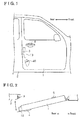
- Fig. 1 illustrates a front view of a vehicle door
- Fig. 2 illustrates a flat view of the vehicle door
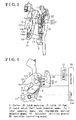
- Fig. 3 illustrates an oblique perspective view of a latch mechanism
- Fig. 4 illustrates a front view of the latch mechanism
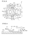
- Fig. 5 illustrates a front view of a latch switch
- Fig. 6 illustrates a cross section of the latch switch
- Fig. 7A illustrates a front view indicating an actuation of the latch mechanism
- Fig. 7B illustrates a front view indicating an actuation of the latch switch
- Fig. 8A illustrates a front view indicating an actuation of the latch mechanism
- Fig. 8B illustrates a front view indicating an actuation of the latch switch
- Fig. 9A illustrates a front view indicating an actuation of the latch mechanism
- Fig. 9B illustrates a front view indicating an actuation of the latch switch
- Fig. 10A illustrates a front view indicating an actuation of the latch mechanism
- Fig. 10B illustrates a front view indicating an actuation of the latch switch
- Fig. 11 illustrates a graph indicating correlations among a position of the vehicle door, output signals from the latch switch and a pawl switch and a drive signal outputted from an electric motor related to the embodiment
- Fig. 12 illustrates a graph Indicating correlations among a position of the vehicle door, output signals from the latch switch and a pawl switch and a drive signal outputted from an electric motor related to a modified embodiment.
- Fig. 1 illustrates a front view indicating a vehicle door 1 to which a door lock apparatus related to the present invention is applied.
- Fig. 2 illustrates a plain view of the vehicle door 1 in Fig. 1 .
- the vehicle door 1 is connected to a vehicle body 2 by means of a hinge allowing the vehicle door 1 to make a swing movement relative to the hinge in order to open/close a door opening of the vehicle body 2.
- a state where the door opening is opened will be referred to as a state where the vehicle door 1 is opened, and a state where the door opening is closed will be referred to as a state where the vehicle door 1 close.
- a latch mechanism 10 is mounted to the vehicle door 1 at a rear end portion thereof in a front-rear direction of the vehicle.
- the latch mechanism 10 is engagable with a striker 3 provided at the vehicle body 2 in order to hold the vehicle door 1 in a slightly opened state or in a fully closed state.
- the striker 3 is formed in a U-shape or an approximate U-shape having corners.
- the latch mechanism 10 is connected to each of an outside door handle 4 provided at an outer surface of the vehicle door 1 and an inside door handle 5 provided at an inner surface of the vehicle door 1, and in a case where one of the door handles 4 and 5 is operated, an operation force on the basis of the operation of the door handle 4 or 5 is transmitted to the latch mechanism 10 so that the latch mechanism 10 is operated so as to disengage the striker 3 in order to allow the vehicle door 1 to be opened.
- the latch mechanism 10 is also connected to an actuator 40 serving as a driving means and is mounted within the vehicle door 1 (e.g., provided between the inner surface and the outer surface of the vehicle door 1), and when the vehicle door 1 is in the slightly opened state and the actuator 40 is driven, a driving force of the actuator 40 is transmitted to the latch mechanism 10 so that the latch mechanism 10 is operated so as to be engaged with the striker 3 in order to move the vehicle door 1 toward the fully closed state (e.g., a closing operation of the vehicle door 1 is execute).
- an actuator 40 serving as a driving means and is mounted within the vehicle door 1 (e.g., provided between the inner surface and the outer surface of the vehicle door 1), and when the vehicle door 1 is in the slightly opened state and the actuator 40 is driven, a driving force of the actuator 40 is transmitted to the latch mechanism 10 so that the latch mechanism 10 is operated so as to be engaged with the striker 3 in order to move the vehicle door 1 toward the fully closed state (e.g., a closing operation of the vehicle door 1 is execute).
- FIG. 3 illustrates an oblique perspective view of the latch mechanism 10 and a structure of its surroundings.
- Fig. 4 illustrates a front view of the latch mechanism 10 and its surroundings.
- the latch mechanism 10 includes a rotational shaft 11 and a latch 12.
- the rotational shaft 11 is formed in a pin shape and rotatably supported by a bracket that Is fixed to the vehicle door 1 of the vehicle.
- the latch 12 is formed in a plate shape and attached to one end portion (a left end portion in Fig. 3 ) of the rotational shaft 11 so as to be integrally rotatable with the rotational shaft 11.
- the latch 12 is formed in an approximate U-shape having two arms and a mouth portion formed between the arms.
- the arms are referred to as first and second arm portions 12b and 12c, and the mouth portion is referred to as a striker receiving portion 12a.
- the first arm portion 12b is positioned at the side of the clockwise direction (e.g., at a right side), and the second arm portion 12c is positioned at the side of the counterclockwise direction (e.g., at a left side).
- a first engaging portion 12d is formed at an end portion of the first arm portion 12b at a position not facing the striker receiving portion 12a.
- a second engaging portion 12e is formed at an end portion of the second arm portion 12c at a position facing the striker receiving portion 12a.
- the latch 12 is biased by a latch biasing spring so as to rotate in a clockwise direction in Fig. 4 so as to be maintained at a predetermined position.
- the latch mechanism 10 further includes a rotational shaft 13 and a pawl 14.
- the rotational shaft 13 is formed in a pin shape and is provided at a lower portion of the latch 12 in Fig. 3 so as to be rotatably supported by the bracket.
- the pawl 14 is formed in a plate shape and is attached to an end portion (a left end portion in Fig. 3 ) of the rotational shaft 13 so as to be integrally rotatable with the rotational shaft 13.
- a position of the pawl 14 in an axial direction thereof is identical to that of the latch 12.
- An engagable end portion 14a is formed so as to protrude from the rotational shaft 13 in a radial direction thereof.
- the pawl 14 is biased by a pawl biasing spring so as to rotate in a counterclockwise direction in Fig. 4 so as to be maintained at a predetermined initial position.
- a pawl lift lever 15 is connected to the other end portion (the right end portion in Fig. 3 ) of the rotational shaft 13 so as to be integrally rotatable with the rotational shaft.
- the pawl lift lever 15 is formed in a plate shape, and the operation force from the door handles 4 or 5 is transmittable by the pawl lift lever 15.
- a pawl switch 16 is provided in order to detect a rotation of the pawl lift lever 15, in other words a rotation of the pawl 14.
- the pawl switch 16 is in a conductive state (ON state).
- the pawl switch 16 is in a nonconductive state (OFF state).
- a latch switch 31 including a rotary switch is connected to the other end portion (right end portion in Fig. 3 ) of the rotational shaft 11.
- a holder 30 formed in a tray shape and made of resin so as to extend in a direction being orthogonal to the rotation shaft 11 is fixed to the vehicle door 1 so as to face the other end portion of the rotational shaft 11.
- the latch switch 31 includes a stationary member 32 and a movable member 33.
- the stationary member 32 is attached to the holder 30, and the movable member 33 is engaged with a connecting pin 17 so as to rotate integrally with the latch 12.
- the connecting pin 17 is formed so as to extend toward the holder 30 and is arranged so as to be parallel to the rotational shaft 11.
- the stationary member 32 includes a commonly used electrode 34, a half/full latch detection electrode 35 and an intermediate position detection electrode 36.
- Each of the electrodes 34, 35 and 36 is arranged in a manner where a certain portion thereof is embedded in a terminal block 32a having insulation properties, and an electrode plane of each of the electrodes 34, 35 and 36 is exposed to the outside (see Fig. 6 ).
- the commonly used electrode 34 is formed so as to include a extending piece 34a formed so as to extend in a radial direction of the rotational shaft 11 and a commonly used terminal 34b formed in a sector shape at the end portion of the commonly used electrode 34 at the side of the rotational shaft 11 so as to extend in a circumferential direction relative to the rotational shaft 11.
- the half/full latch detection electrode 35 is formed so as to include an extending piece 35a and a half/full latch detectable fixed terminal 35b.
- the extending piece 35a is arranged below the extending piece 34a and is formed so as extend approximately parallel to the extending piece 34a.
- the half/full latch detectable fixed terminal 35b serving as a half latch detectable fixed terminal and a full latch detectable fixed terminal, is formed in a sector shape at an end of the extending piece 35a at the side of the rotational shaft 11 so as to extend upwardly toward the rotational shaft 11.
- the intermediate position detection electrode 36 is formed so as to include an extending piece 36a and an intermediate position detectable fixed terminal 36b.
- the extending piece 36a is arranged above the extending piece 34a and is formed so as to extend approximately parallel to the extending piece 34a.
- the intermediate position detectable fixed terminal 36b is formed in a sector shape at an end portion of the extending piece 36a at the side of the rotational shaft 11 so as to extend downwardly toward the rotational shaft 11.
- the commonly used electrode 34, the half/full latch detection electrode 35 and the intermediate position detection electrode 36 are provided in a manner where the commonly used terminal 34b, the half/full latch detectable fixed terminal 35b and the intermediate position detectable fixed terminal 36b are positioned on a concentric circle having a center point corresponding to an axis of the rotational shaft 11 and arranged so as to be distant from each other in a circumferential direction,
- a movable electrode 37 provided at the movable member 33 is supported by the stationary member 32 (the commonly used terminal 34b, the half/full latch detectable fixed terminal 35b and the intermediate position detectable fixed terminal 36b) in a manner where the movable electrode 37 contacts the stationary member 32 at points and is mainly slightly distant therefrom.
- the movable electrode 37 includes a ring portion 37a and a plurality of extending pieces, especially three radially extending pieces 37b, 37c and 37d.
- the ring portion 37a is formed in a ring shape, and the rotational shaft is inserted into the ring portion 37a so as to be rotatable.
- Each of the radially extending pieces 37b, 37c and 37d are formed so as to extend from the ring portion 37a outwardly in a radial direction. Each of the radially extending pieces 37b, 37c and 37d are arranged so as to be equally distant from each other.
- the movable electrode 37 further includes a pair of circumferentially extending pieces 37e and a pair of connecting terminals 37f.
- the circumferentially extending pieces 37e are formed so as to extend from the radially extending piece 37b toward the adjacent radially extending piece 37d in a circumferential direction.
- Each of the circumferentially extending pieces 37e is arranged on a concentric circle having a same central point. As illustrated in Fig.
- each of the circumferentially extending pieces 37e is bent downwardly toward the terminal block 32a (downwardly in Fig. 6 ) and further bent upwardly so as to form the V-shaped connecting terminal 37f.
- the connecting terminal 37f is normally slidable on the commonly used terminal 34b within a range of a rotation of the latch 12.
- the movable electrode 37 further includes a pair of circumferentially extending pieces 37g and a pair of half/full latch detectable movable terminals 37h.
- the circumferentially extending pieces 37g are formed so as to extend from the radially extending piece 37c toward the adjacent radially extending piece 37b in a circumferential direction.
- Each of the circumferentially extending pieces 37g is arranged on a concentric circle having a same central point.
- An end portion of the each of the circumferentially extending pieces 37g is bent downwardly toward the terminal block 32a (downwardly in Fig. 6 ) and further bent upwardly so as to form the V-shaped half/full latch detectable movable terminal 37h.
- the half/full latch detectable movable terminal 37h is normally slidable on the half/full latch detectable fixed terminal 35b.
- the half/full latch detectable movable terminal 37h forms a half/full latch detection switch 38, together with half/full latch detectable fixed terminal 36b, serving as a half latch detection switch (e.g., half latch detection mechanism) and serving also as a full latch detection switch (e.g., full latch detection mechanism), accordingly the half/full latch detection switch 38 is also referred to as a dual function switch,
- the half/full latch detection switch 38 is turned to be in the ON state when the commonly used electrode 34 and the half/full latch detection electrode 35 are conducted in a case where the half/full latch detectable movable terminal 37h slides on the half/full latch detectable fixed terminal 35b.
- the half/full latch detection switch 38 Is turned to be in the OFF state when the commonly used electrode 34 and the half/full latch detection electrode 35 are non-conducted in a case where the half/full latch detectable movable terminal 37h protrudes so as to be apart from the half/full latch detectable fixed terminal 35b,
- the movable electrode 37 further includes a pair of circumferentially extending pieces 37i and a pair of intermediate position detectable movable terminals 37j.
- the circumferentially extending pieces 37i are formed so as to extend from the radially extending piece 37d toward the adjacent radially extending piece 37c in a circumferential direction.
- Each of the circumferential extending pieces 37i is arranged on a concentric circle having a same central point.
- An end portion of the each of the circumferentially extending pieces 37i is bent downwardly toward the terminal block 32a (downwardly in Fig. 6 ) and further bent upwardly so as to form the V-shaped intermediate position detectable movable terminal 37j.
- the intermediate position detectable movable terminal 37j is normally slidable on the intermediate position detectable fixed terminal 36b.
- the intermediate position detectable movable terminal 37j forms, together with the intermediate position detectable fixed terminal 36b, the intermediate position detection switch 39 serving as an intermediate position detection mechanism.
- the intermediate position detection switch 39 is turned to be in the ON state when the commonly used electrode 34 and the intermediate position detection electrode 36 are conducted in a case where the Intermediate position detectable movable terminal 37j slides on the intermediate position detectable fixed terminal 36b.
- the intermediate position detection switch 39 is turned to be in the OFF state when the commonly used electrode 34 and the intermediate position detection electrode 36 are non-conducted in a case where the intermediate position detectable movable terminal 37j protrudes so as to be apart from the intermediate position detectable fixed terminal 36b.
- the latch switch 31 includes a single switch structure in which the intermediate position detection switch 39 and the half/full latch detection switch 38 (the half latch detection switch and the full latch detection switch) are integrated.
- the latch 12 is biased by the latch biasing spring so as to be held at the predetermined position and postures in a manner where the striker receiving portion 12a thereof opens in a direction where the striker 3 enters the striker receiving portion 12a by the closing operation of the vehicle door 1 (see Fig. 4 and Fig. 7A ).
- the pawl 14 is biased by the pawl biasing spring so as to be held at the Initial position in a manner where the engagable end portion 14a of the pawl 14 contacts an outer surface of the second arm portion 12c of the latch 12.
- a state of the latch mechanism 10 at this point is referred to as an unlatched state, and a position of the latch 12 corresponding to the latch mechanism 10 being in the unlatched state is referred to as an unlatched position.
- the striker 3 When the striker 3 enters within the striker receiving portion 12a in accordance with the closing operation of the vehicle door 1, the striker 3 pushes an inner surface of the striker receiving portion 12a, and the latch 12 is rotated in a counterclockwise direction against the biasing force of the latch biasing spring. At a position where the second engaging portion 12e of the latch 12 engages the engagable end portion 14a of the pawl 14, the rotation of the latch 12 is stopped by means of the latch 14. (see Fig. 8A ). The vehicle door 1 at this point is in a slightly opened state where the striker 3 is engaged with the striker receiving portion 12a so as not to come out therefrom.
- the state of the latch mechanism 10 at this point is referred to as a half latched state, and the position of the latch 12 corresponding to the latch mechanism 10 being in the half latched state is referred to as the half latch position.
- the pawl 14 is rotated in accordance with the rotation of the latch 12.
- the pawl 14 is returned to its initial position, thereby the rotation of the latch 12 is stopped. Then the rotation of the pawl 14 is stopped.
- the striker 3 when the striker 3 further enters the striker receiving portion 12a in accordance with the closing operation of the vehicle door 1, the striker 3 presses the inner surface of the striker receiving portion 12a, and the latch 12 is further rotated in the counterclockwise direction against the biasing force of the latch biasing spring, and then the first engaging portion 12d engages with the engagable end portion 14a so that the rotation of the latch 12 is stopped (see Fig. 10A ).
- the vehicle door 1 is in the fully closed state where the striker 3 is engaged with the striker receiving portion 12a so as not to come out therefrom.
- a state of the latch mechanism 10 at this point is referred to as the fully latched state, and the posture of the latch 12 corresponding to the latch mechanism 10 being in the fully latched state is referred to as the fully latched position.
- the pawl 14 is rotated in accordance with the rotation of the latch 12. After the latch 12 is rotated so as to reach the fully latched position, the pawl 14 is returned to its initial position, at the same time the rotation of the latch 12 is stopped by means of the pawl 14, and then the rotation of the pawl 14 is stopped.
- the pawl 14 at the half latched state or the fully latched state is rotated in the clockwise direction against the biasing force of the pawl biasing spring, and then the engagable end portion 14a is disengaged from the first engaging portion 12d or the second engaging portion 12e.
- the latch 12 is rotated in the clockwise direction in accordance with the biasing force applied by the latch biasing spring while the inner surface of the striker receiving portion 12a presses the striker 3. Then, the striker 3 is disengaged from the striker receiving portion 12a, and the vehicle door 1 is allowed to be opened.
- the latch 12 is connected to the electric motor 41 provided at the actuator 40 (see Fig. 4 ), and when the latch 12 is in the half latched state, the latch 12 is rotated in the counterclockwise direction by means of the electric motor 41, so that the latch mechanism 10 is turned to be in the fully latched state. In accordance with this operation, the vehicle door 1 is moved toward vehicle body 2 so as to be changed from the slightly opened state to the fully closed state.
- the half/full latch detectable movable terminal 37h contacts the half/full latch detectable fixed terminal 35b while the pawl 14 is rotated corresponding to the rotation of the latch 12, accordingly the half/full latch detection switch 38 is turned to be in the ON state from the OFF state in a range (time period) in which the pawl switch 16 is in the ON state.
- the intermediate position detectable movable terminal 37j is still contacting the intermediate position detectable fixed terminal 36b, the intermediate position detection switch 39 is in the ON state.
- the half/full latch detection switch 38 detects the half latch position or the fully latched position on the basis of the state between the half/full latch detectable fixed terminal 35b and the half/full latch detectable movable terminal 37h, and specifically, the half latch position is detected when the state between the terminals (the half/full latch detectable fixed terminal 35b and the half/full latch detectable movable terminal 37h) is in one of the conducting and non-conducting states, and the fully latched position is detected when the state between the terminals is in the other of the conducting and non-conducting states.
- the half/full latch detection switch 38 detects the half latch position when the conducting state between the half/full latch detectable fixed terminal 35b and the half/full latch detectable movable terminal 37h is established, and the half/full latch detection switch 38 detects the fully latched position when the non-conducting state between the half/full latch detectable fixed terminal 35b and the half/full latch detectable movable terminal 37h is established.
- the half/full latch detectable movable terminal 37h does not contact the half/full latch detectable fixed terminal 35b while the pawl 14 is rotated corresponding to the rotation of the latch 12, accordingly the half/full latch detection switch 38 is turned to be in the OFF state from the ON state in the range (time period) in which the pawl switch 16 is in the ON state.
- the intermediate position detectable movable terminal 37j does not contact the intermediate position detectable fixed terminal 36b, the intermediate position detection switch 39 is still in the OFF state.
- the latch switch 31 (the half/full latch detection switch 38 and the intermediate position detection switch 39) and the pawl switch 1G are electrically connected to a controller 50 serving as a controlling means, and the controller 50 controls the actuator 40 (electric motor 40), which Is electrically connected thereto, so as to be driven corresponding to output signals from the latch switch 31 and the pawl switch t6..
- Fig. 1 illustrates a graph indicating correlations among the position of the vehicle door 1 (opened/closed position) corresponding to the position of the latch 12, the output signal from the latch switch 31 (the half/full latch detection switch 38 and the intermediate position detection switch 39), the output signal from the pawl switch 16 and a drive signal outputted from the actuator 40 (electric motor 41).
- a range indicated by a shaded rectangle existing before and after each ON/OFF timing corresponds to a range of variability of the timing.
- the output signals from the latch switch 31 and the pawl switch 16 are set in a manner where ON/OFF timings thereof including the variability are not overlapping each other.
- the controller 50 detects the slightly opened state of the vehicle door 1 on the basis of the ON state of the output signal from the half/full latch detection switch 38, the ON state of the output signal from the intermediate position detection switch 39 and OFF state of the output signal from the pawl switch 16.
- the controller 50 turns on the drive signal from the electric motor 41 on the basis of the detection of the slightly opened state of the vehicle door 1 at timing T4. Then, the latch 12 is driven by the electric motor 41 and starts its rotation while the pawl 14 is in the initial position, and the closing operation of the vehicle door 1 is started. Once the latch 12 reaches the intermediate position, the output signal being in the ON state from the intermediate position detection switch 39 is turned to be in the OFF state (timing T5). On the basis of the OFF signal from the intermediate position detection switch 39, the controller 50 temporally turns off (OFF state) the drive signal of the electric motor 41, and then the controller 50 turns on (ON state) the drive signal of the electric motor 41 once again (returned).
- the closing operation of the vehicle door 1 is temporally stopped on the basis of the OFF state drive signal of the electric motor 41, and then the closing operation of the vehicle door 1 is started again on the basis of the ON state drive signal of the electric motor 41.
- a position of the vehicle door 1 (timing T5) at which the closing operation of the vehicle door 1 is temporally stopped is set to be closer to the position corresponding to the half latched state than the position corresponding to the fully latched state, so that the vehicle door 1 may be temporally stopped at a relatively early timing at which a motor output is relatively low and a door opening is relatively large.
- the controller 50 executes a time control for temporally turning off the drive signal of the electric motor 41 by use of an internal timer 50a.
- the controller 50 detects the fully closed state of the vehicle door 1 on the basis of OFF state of the output signal from the haif/full latch detection switch 38, the OFF state of the output signal from the intermediate position detection switch 39 and the OFF state of the output signal from the pawl switch 16.
- the controller 50 turns off the drive signal of the electric motor 41 on the basis of the detection of the fully closed state of the vehicle door 1. Then, the drive of the electric motor 41 is stopped, and the closing operation of the vehicle door 1 is completed.
- a period between the timings T0 and T1 is referred to as [1]
- a period between the timings T1 and T2 is referred to as [2]
- a period between the timings T2 and T3 is referred to as [3]
- a period between the timings T3 and T4 is referred to as [4]
- a period between the timings T4 and T5 is referred to as [5]
- a period between the timings T5 and T6 is referred to as [6]
- a period between the timings T6 and T7 is referred to as [7]
- a period between the timings T7 and T8 is referred to as [8].
- Each period [1] through [8] has a unique pattern of ON/OFF states of the half/full latch detection switch 38, the intermediate position detection switch 39 and the pawl switch 16. Specifically, in the period [1], the half/full latch detection switch 38 is in the OFF state, the intermediate position detection switch 39 is in the ON state and the pawl switch 16 is In the OFF state (OFF-ON-OFF). In the period [2], the half/full latch detection switch 38 is in the OFF state, the intermediate position detection switch 39 is in the ON state and the pawl switch 16 is in the ON state (OFF-ON-ON).
- the half/full latch detection switch 38 is in the ON state, the intermediate position detection switch 39 is in the ON state and the pawl switch 16 is in the ON state (ON-ON-ON).
- the half/full latch detection switch 38 is in the ON state, the intermediate position detection switch 39 is in the ON state and the pawl switch 16 is in the OFF state (ON-ON-OFF).
- the half/full latch detection switch 38 is in the ON state, the intermediate position detection switch 39 is in the OFF state and the pawl switch 16 is in the OFF state (ON-OFF-OFF).
- the half/full latch detection switch 38 is in the ON state, the intermediate position detection switch 39 is in the OFF state and the pawl switch 16 is in the ON state (ON-OFF-ON),
- the half/full latch detection switch 38 is in the OFF state, the intermediate position detection switch 39 is in the OFF state and the pawl switch 16 is in the ON state (OFF-OFF-ON).
- the half/full latch detection switch 38 is in the OFF state, the intermediate position detection switch 39 is in the OFF state and the pawl switch 16 is in the OFF state (OFF-OFF-OFF).
- ON/OFF patterns in the periods [4] through [7], in which the electric motor 41 is driven in order to rotate the vehicle door 1 being in the slightly opened state to be in the fully closed state, may not overlap any ON/OFF patterns in the periods [1] through [3].
- the vehicle door 1 may be controlled by the controller so as to start or continue the closing operation of the vehicle 1.
- the door lock apparatus in the embodiment may be modified as follows. As illustrated in the graph of Fig. 12 , timings where the half/full latch detection switch is turned ON/OFF may be reversed from the timings indicated in the graph of Fig. 11 . In other words, ON/OFF pattern of the half/full latch detection switch may be reversed. In this modified example, results similar to the embodiment may be obtained.
- the rotation of the pawl 14 in the embodiment may be directly detected by the pawl switch, not using the pawl lift lever 15. Further, a half latch detection switch and a full latch detection switch may be provided separately instead of the integrated half/full latch detection switch.
- the door lock apparatus in the embodiment may include the intermediate position detection switch having a switch structure in which one of the half latch detection switch and the full latch detection switch is integrated. Further, each of the half latch detection switch, the full latch detection switch and the intermediate position detection switch may include a separated switch structure.
- the intermediate position at which the drive of the actuator is temporally stopped may be detected by a rotation sensor including a hall element.
- the intermediate position may be detected on the basis of the elapsed time after the vehicle door 1 is rotated so as to reach the slightly opened state.
- the door lock apparatus in the embodiment may be applied to a slide type vehicle door.
- a door lock apparatus includes a latch mechanism having a latch adapted to be supported by a vehicle door so as to be freely rotatable and being engagable with a striker provided at a vehicle body and having a pawl adapted to be supported by the vehicle door so as to be freely rotatable and stopping a rotation of the latch being engaged with the striker, at a half latched position and a fully latched position of the latch, in order to maintain the vehicle door at a slightly opened state and a fully closed state, half latch detection mechanism coupled to the latch for detecting a state where the latch is in the half latched position, full latch detection mechanism coupled to the latch for detecting a state where the latch is in the fully latched position, driving means for rotating the latch being in the half latched position toward the fully latched position, intermediate position detection mechanism coupled to the latch for detecting that the latch is in an intermediate position between the half latched position and the fully latched position and controlling means for controlling the driving means to start the drive of the driving means in
- the drive of the actuator 40 Is temporally stopped when the latch 12 is slightly rotated from the half latch position and reaches the intermediate position.
- the closing operation of the vehicle door 1 is temporally stopped. Accordingly, even for a person whose audibility is relatively low, he/she may physically recognize the temporal closing operation of the vehicle door 1 on the basis of the temporal stop. Further, taking advantage of this temporal stop of the actuator 40 (e.g., the temporal stop of the closing operation of the vehicle door 1), an object insertion between the vehicle door 1 and the vehicle body 2 may be avoidable.
- the intermediate position detection mechanism is an intermediate position detection switch that is a contact type switch and Includes an intermediate position detectable fixed terminal adapted to be fixed to the vehicle door and an intermediate position detectable movable terminal connected to the latch so as to be rotatable integrally therewith and turning a state between the intermediate position detectable fixed terminal and the intermediate position detectable movable terminal from one of conducting and non-conducting states to the other of the conducting and non-conducting states, when the latch is in an intermediate position.
- the intermediate position detection switch 39 which is a contact type switch and includes the intermediate position detectable fixed terminal 36b and the intermediate position detectable movable terminal 37j, may detect the intermediate position with high accuracy, Further, compared to another rotation sensor having a hall element and the like, the intermediate position detection switch 39 is configured with a simpler structure and its cost may be reduced.
- the half latch detection mechanism is a half latch detection switch that is a contact type switch and includes a half latch detectable fixed terminal adapted to be fixed to the vehicle door and a half latch detectable movable terminal connected to the latch so as to be rotatable integrally therewith and turning a state between the half latch detectable fixed terminal and the half latch detectable movable terminal from one of conducting and non-conducting states to the other of the conducting and non-conducting states, when the latch is in a half latched position
- the full latch detection mechanism is a full latch detection switch that is a contact type switch and includes a full latch detectable fixed terminal adapted to be fixed to the vehicle door and a full latch detectable movable terminal connected to the latch so as to be rotatable integrally therewith and turning a state between the full latch detectable fixed terminal and the full latch detectable movable terminal from one of conducting and non-conducting states to the other of the conducting and non-conducting states, when the latch is in a fully latched position, and
- the intermediate position detection switch 39 includes a switch structure (e.g., a rotary switch) in which the intermediate position detection switch 39 is integrated with the half/full latch detection switch 38 (the half latch detection switch and the full latch detection switch), accordingly the door lock apparatus may be downsized.
- a switch structure e.g., a rotary switch
- the door lock apparatus further includes the half/full latch detection switch having a dual function as the half latch detection switch and the full latch detection switch, and when the latch is in either one of the half latched position and the fully latched position, the half latched position is detected when a state between the half/full latch detectable fixed terminal, serving as a half latch detectable fixed terminal and a full latch detectable fixed terminal, and the half/full latch detectable movable terminal, serving as a half latch detectable movable terminal and a full latch detectable movable terminal, is in one of conducting and non-conducting states, and the fully latched position is detected when the state between the half/full latch detectable fixed terminal and the half/full latch detectable movable terminal is in the other of conducting and non-conducting states.
- the half/full latch detection switch having a dual function as the half latch detection switch and the full latch detection switch
- the half/full latch detection switch 38 is used for both of the half latch detection and the full latch detection, the number of the parts of the door lock apparatus may be reduced. Further, because there is no need to provide plural terminals for the half/full latch detection switches, a cost for the terminal may be reduced, and furthermore, space in which the plural terminals are supposed to be provided may be saved. Consequently, workloads and costs related to the positional change of the surrounding components related to the half/full latch detection switch may be reduced.
- the half/full latch detection switch 38 detects the half latch position when the conducting state between the half/full latch detectable fixed terminal 35b and the half/full latch detectable movable terminal 37h is established, and the half/full latch detection switch 38 detects the fully latched position when the non-conducting state between the half/full latch detectable fixed terminal 35b and the half/full latch detectable movable terminal 37h is established, the half/full latch detection switch 38 may detect the half latch position or the fully latched position without confusion.
- the door lock apparatus further includes a pawl switch changing a state thereof, when the pawl is rotated, from one of conducting and non-conducting states to the other of the conducting and non-conducting states, the half latched position and the fully latched position detected by the half/full latch detection switch are set in a range within which the pawl is rotated, the intermediate position detected by the intermediate position detection switch is set in a range within which the pawl is not rotated, the controlling means controls the driving means to start the drive of the driving means when the state of the pawl switch is changed so as to be in one of the conducting and non-conducting states after the half latched position is detected by the half/full latch detection switch, and the controlling means controls the driving means to stop the drive of the driving means when the state of the pawl switch is changed so as to be in one of the conducting and non-conducting states after the fully latched position is detected by the half/full latch detection switch,
- the intermediate position detection switch (the intermediate position detectable fixed terminal and the intermediate position detectable movable terminal) being in the conducting state is changed to be in the non-conducting state. Then the pawl Is rotated in accordance with the rotation of the latch toward its fully latched position, accordingly, the pawl switch being in the non-conducting state is changed to be in the conducting state. While the pawl is rotated, the half/full latch detection switch (the half/full latch detectable fixed terminal and the half/full latch detectable movable terminal) being in the conducting state is changed to be in the non-conducting state.
- each period has a unique pattern of ON/OFF states of the half/full latch detection switch 38, the intermediate position detection switch 39 and the pawl switch 16 in a period between when the vehicle door 1 is opened and when the closing operation of the vehicle door is completed. Accordingly, when the actuator 40 needs to be driven in order to execute the closing operation of the vehicle door 1, an operational error on the actuator 40 on the basis of a misdetection of the opened state of the vehicle door 1 may be avoidable.
- vehicle door 1 may be controlled by the controller so as to start or continue the closing operation of the vehicle 1.
- a position of the vehicle door 1 (timing T5) at which the closing operation of the vehicle door 1 is temporally stopped is set to be closer to the position corresponding to the half latched state (timing T3) than the position corresponding to the fully latched state (timing T8), so that the vehicle door 1 may be temporally stopped at a relatively early timing at which a motor output is relatively low and a door opening is relatively large.
Landscapes
- Lock And Its Accessories (AREA)
Abstract
Description
- The present invention relates to a door lock apparatus.
- According to a known door lock apparatus, for example disclosed in JPH9291737A, when a vehicle door is ajar (e.g., door is in a slightly opened state), the vehicle door is operated to be closed so as to be In a fully closed state by rotating a latch of the door lock apparatus being in a half latched position so as to be in a fully latched position.
- Because the closing operation of the door lock apparatus general continues till the vehicle door reaches its fully closed state, there is a need to consider various measures for avoiding an object insertion between the vehicle door and a vehicle body. For example, an alarm apparatus may be provided in order to make a sound of an alarm to notice the closing operation of a user. In this case, the user may avoid the object insertion on the basis of the sound of the alarm, however; the alarm may not be appropriately recognized by a user, for example a user whose audibility is relatively low.
- A need thus exists to provide a door lock apparatus of the vehicle by which an object insertion between a vehicle door and a vehicle body may surely be avoided by a user so as to surely recognize a closing operation of the vehicle door being in a slightly opened state toward its fully closed state.
- According to an aspect of the present invention, a door lock apparatus includes a latch mechanism having a latch adapted to be supported by a vehicle door so as to be freely rotatable and being engagable with a striker provided at a vehicle body and having a pawl adapted to be supported by the vehicle door so as to be freely rotatable and stopping a rotation of the latch being engaged with the striker, at a half latched position and a fully latched position of the latch, in order to maintain the vehicle door at a slightly opened state and a fully closed state, a half latch detection mechanism coupled to the latch for detecting a state where the latch is in the half latched position, a full latch detection mechanism coupled to the latch for detecting a state where the latch is in the fully latched position, driving means for rotating the latch being in the half latched position toward the fully latched position, an intermediate position detection mechanism coupled to the latch for detecting that the latch is in an intermediate position between the half latched position and the fully latched position and controlling means for controlling the driving means to start the drive of the driving means in order to rotate the latch toward the fully latched position on the basis of the detection that the latch is in the half latched position, to stop the drive of the driving means on the basis of the detection that the latch is in the fully latched position and to temporally stop the drive of the driving means on the basis of the detection that the latch is in the intermediate position.
- Thus, after an actuator is driven in order to rotate the latch being in the half latch position so as to be in the fully latched position, the drive of the actuator is temporally stopped when the latch is slightly rotated from the half latched position and reaches the intermediate position. Specifically, after the vehicle door being in the slightly opened state is slightly rotated toward the fully closed state (a slight actuation is executed), the closing operation of the vehicle door is temporally stopped. Accordingly, even for a person whose audibility is relatively low, he/she may physically recognize the temporal closing operation of the vehicle door on the basis of the temporal stop. Further, taking advantage of this temporal stop of the actuator (e.g., the temporal stop of the closing operation of the vehicle door), an object insertion between the vehicle door and the vehicle body may be avoidable.
- According to another aspect of the present invention, the intermediate position detection mechanism is an intermediate position detection switch that is a contact type switch and includes an intermediate position detectable fixed terminal adapted to be fixed to the vehicle door and an intermediate position detectable movable terminal connected to the latch so as to be rotatable integrally therewith and turning a state between the intermediate position detectable fixed terminal and the intermediate position detectable movable terminal from one of conducting and non-conducting states to the other of the conducting and non-conducting states, when the latch is in an intermediate position.
- Thus, the intermediate position detection switch, which is a contact type switch and includes the intermediate position detectable fixed terminal and the intermediate position detectable movable terminal, may detect the intermediate position with high accuracy. Further, compared to another rotation sensor having a hall element and the like, the intermediate position detection switch is configured with a simpler structure and its cost may be reduced.
- According to further aspect of the present invention, the half latch detection mechanism is a half latch detection switch that is a contact type switch and includes a half latch detectable fixed terminal adapted to be fixed to the vehicle door and a half latch detectable movable terminal connected to the latch so as to be rotatable integrally therewith and turning a state between the half latch detectable fixed terminal and the half latch detectable movable terminal from one of conducting and non-conducting states to the other of the conducting and non-conducting states, when the latch is in a half latched position, the full latch detection mechanism is a full latch detection switch that is a contact type switch and Includes a full latch detectable fixed terminal adapted to be fixed to the vehicle door and a full latch detectable movable terminal connected to the latch so as to be rotatable integrally therewith and turning a state between the full latch detectable fixed terminal and the full latch detectable movable terminal from one of conducting and non-conducting states to the other of the conducting and non-conducting states, when the latch is in a fully latched position, and the door lock apparatus has a structure where the intermediate position detection switch is integrated with at least one of the half latch detection switch and the full latch detection switch.
- Thus, the intermediate position detection switch includes a switch structure in which the intermediate position detection switch is integrated with the half latch detection switch and the full latch detection switch, accordingly the door lock apparatus may be downsized.
- According to another aspect of the present invention, the door lock apparatus further includes a half/full latch detection switch having a dual function as the half latch detection switch and the full latch detection switch, and when the latch is in either one of the half latched position and the fully latched position, the half latched position is detected when a state between the half/full latch detectable fixed terminal, serving as a half latch detectable fixed terminal and a full latch detectable fixed terminal, and the half/full latch detectable movable terminal, serving as a half latch detectable movable terminal and a full latch detectable movable terminal, is in one of conducting and non-conducting states, and the fully latched position is detected when the state between the half/full latch detectable fixed terminal and the half/full latch detectable movable terminal is in the other of conducting and non-conducting states.
- Thus, because the half/full latch detection switch is used for both of the half latch detection and the full latch detection, the number of the parts of the door lock apparatus may be reduced. Further, because there is no need to provide plural terminals for the half/full latch detection switches, a cost for the terminal may be reduced, and furthermore, space in which the plural terminals are supposed to be provided may be saved. Consequently, workloads and costs related to the positional change of the surrounding components related to the half/full latch detection switch may be reduced. Moreover, because the half/full latch detection switch detects the half latch position, for example when the conducting state between the half/full latch detectable fixed terminal and the half/full latch detectable movable terminal is established, and the half/full latch detection switch detects the fully latched position, for example when the non-conducting state between the half/full latch detectable fixed terminal and the half/full latch detectable movable terminal is established, the half/full latch detection switch may detect the half latch position or the fully latched position without confusion.
- According to an aspect of the present invention, the door lock apparatus further includes a pawl switch changing a state thereof, when the pawl is rotated, from one of conducting and non-conducting states to the other of the conducting and non-conducting states, the half latched position and the fully latched position detected by the half/full latch detection switch are set in a range within which the pawl is rotated, the intermediate position detected by the intermediate position detection switch is set in a range within which the pawl is not rotated, the controlling means controls the driving means to start the drive of the driving means when the pawl switch being in the other of the conducting and non-conducting states Is changed so as to be in the one of the conducting and non-conducting states after the half latched position is detected by the half/full latch detection switch, and the controlling means controls the driving means to stop the drive of the driving means when the pawl switch being in the other of the conducting and non-conducting states is changed so as to be in the one of the conducting and non-conducting states after the fully latched position is detected by the half/full latch detection switch.
- In this configuration, when the vehicle door being in the opened state is closed, because the pawl is rotated in accordance with the rotation of the latch rotating so as to be in the half latched position, the pawl switch being in the non-conducting state is changed to be in the conducting states, and while the pawl switch is in the conducting state (while the pawl is rotating), the half/full latch detection switch (the half/full latch detectable fixed terminal and the half/full latch detectable movable terminal) being in the non-conducting state is changed to be in the conducting state. When the rotation of the pawl is finished, the pawl switch being in the conducting state is changed to be in the non-conducting state. At this timing, the drive of the driving means is started, and the vehicle door starts or continues its closing operation.
- While the pawl is not rotated, the intermediate position detection switch (the intermediate position detectable fixed terminal and the intermediate position detectable movable terminal) being in the conducting state is changed to be in the non-conducting state. Then the pawl is rotated in accordance with the rotation of the latch toward its fully latched position, accordingly, the pawl switch being in the non-conducting state is changed to be in the conducting state. While the pawl is rotated, the half/full latch detection switch (the half/full latch detectable fixed terminal and the half/full latch detectable movable terminal) being in the conducting state is changed to be in the non-conducting state. Then, the rotation of the pawl is finished, and the pawl switch being in the conducting state is changed to be in the non-conducting state. At this point, the drive of the driving means is stopped, as a result, the closing operation of the vehicle door is finished.
- Accordingly, even though the haif/futi latch detection switch has a dual function as the half latch detection and the full latch detection, each period has a unique pattern of ON/OFF states of the half/full latch detection switch, the intermediate position detection switch and the pawl switch in a period between when the vehicle door is opened and when the closing operation of the vehicle door is completed. Accordingly, when the actuator needs to be driven in order to execute the closing operation of the vehicle door, an operational error on the actuator on the basis of a misdetection of the opened state of the vehicle door may be avoidable.
- The foregoing and additional features and characteristics of the present invention will become more apparent from the following detailed description considered with the reference to the accompanying drawings, wherein:
-
Fig. 1 illustrates a front view of a vehicle door; -
Fig. 2 illustrates a flat view of the vehicle door; -
Fig. 3 illustrates an oblique perspective view of a latch mechanism; -
Fig. 4 illustrates a front view of the latch mechanism; -
Fig. 5 illustrates a front view of a latch switch; -
Fig. 6 illustrates a cross section of the latch switch; -
Fig. 7A illustrates a front view indicating an actuation of the latch mechanism; -
Fig. 7B illustrates a front view indicating an actuation of the latch switch;: -
Fig. 8A illustrates a front view indicating an actuation of the latch mechanism; -
Fig. 8B illustrates a front view indicating an actuation of the latch switch; -
Fig. 9A illustrates a front view indicating an actuation of the latch mechanism; -
Fig. 9B illustrates a front view indicating an actuation of the latch switch; -
Fig. 10A illustrates a front view indicating an actuation of the latch mechanism; -
Fig. 10B illustrates a front view indicating an actuation of the latch switch; -
Fig. 11 illustrates a graph indicating correlations among a position of the vehicle door, output signals from the latch switch and a pawl switch and a drive signal outputted from an electric motor related to the embodiment; and -
Fig. 12 illustrates a graph Indicating correlations among a position of the vehicle door, output signals from the latch switch and a pawl switch and a drive signal outputted from an electric motor related to a modified embodiment. - An embodiment related to the present invention will be explained in accordance with the attached drawings.
Fig. 1 illustrates a front view indicating avehicle door 1 to which a door lock apparatus related to the present invention is applied.Fig. 2 illustrates a plain view of thevehicle door 1 inFig. 1 . As illustrated in the plain view ofFig. 2 , thevehicle door 1 is connected to avehicle body 2 by means of a hinge allowing thevehicle door 1 to make a swing movement relative to the hinge in order to open/close a door opening of thevehicle body 2. Hereinafter, a state where the door opening is opened will be referred to as a state where thevehicle door 1 is opened, and a state where the door opening is closed will be referred to as a state where thevehicle door 1 close. Alatch mechanism 10 is mounted to thevehicle door 1 at a rear end portion thereof in a front-rear direction of the vehicle. Thelatch mechanism 10 is engagable with astriker 3 provided at thevehicle body 2 in order to hold thevehicle door 1 in a slightly opened state or in a fully closed state. Thestriker 3 is formed in a U-shape or an approximate U-shape having corners. Thelatch mechanism 10 is connected to each of anoutside door handle 4 provided at an outer surface of thevehicle door 1 and aninside door handle 5 provided at an inner surface of thevehicle door 1, and in a case where one of the door handles 4 and 5 is operated, an operation force on the basis of the operation of thedoor handle latch mechanism 10 so that thelatch mechanism 10 is operated so as to disengage thestriker 3 in order to allow thevehicle door 1 to be opened. - The
latch mechanism 10 is also connected to anactuator 40 serving as a driving means and is mounted within the vehicle door 1 (e.g., provided between the inner surface and the outer surface of the vehicle door 1), and when thevehicle door 1 is in the slightly opened state and theactuator 40 is driven, a driving force of theactuator 40 is transmitted to thelatch mechanism 10 so that thelatch mechanism 10 is operated so as to be engaged with thestriker 3 in order to move thevehicle door 1 toward the fully closed state (e.g., a closing operation of thevehicle door 1 is execute). - A structure of the
latch mechanism 10 will be explained on the basis ofFigs. 3 and 4. Fig. 3 illustrates an oblique perspective view of thelatch mechanism 10 and a structure of its surroundings.Fig. 4 illustrates a front view of thelatch mechanism 10 and its surroundings. Thelatch mechanism 10 includes arotational shaft 11 and alatch 12. Therotational shaft 11 is formed in a pin shape and rotatably supported by a bracket that Is fixed to thevehicle door 1 of the vehicle.
Thelatch 12 is formed in a plate shape and attached to one end portion (a left end portion inFig. 3 ) of therotational shaft 11 so as to be integrally rotatable with therotational shaft 11. Thelatch 12 is formed in an approximate U-shape having two arms and a mouth portion formed between the arms. In the embodiment, the arms are referred to as first andsecond arm portions striker receiving portion 12a. InFig. 4 , thefirst arm portion 12b is positioned at the side of the clockwise direction (e.g., at a right side), and thesecond arm portion 12c is positioned at the side of the counterclockwise direction (e.g., at a left side). A first engagingportion 12d is formed at an end portion of thefirst arm portion 12b at a position not facing thestriker receiving portion 12a. A secondengaging portion 12e is formed at an end portion of thesecond arm portion 12c at a position facing thestriker receiving portion 12a. Thelatch 12 is biased by a latch biasing spring so as to rotate in a clockwise direction inFig. 4 so as to be maintained at a predetermined position. - The
latch mechanism 10 further includes arotational shaft 13 and apawl 14. Therotational shaft 13 is formed in a pin shape and is provided at a lower portion of thelatch 12 inFig. 3 so as to be rotatably supported by the bracket. Thepawl 14 is formed in a plate shape and is attached to an end portion (a left end portion inFig. 3 ) of therotational shaft 13 so as to be integrally rotatable with therotational shaft 13. A position of thepawl 14 in an axial direction thereof is identical to that of thelatch 12. Anengagable end portion 14a is formed so as to protrude from therotational shaft 13 in a radial direction thereof. Thepawl 14 is biased by a pawl biasing spring so as to rotate in a counterclockwise direction inFig. 4 so as to be maintained at a predetermined initial position. - A
pawl lift lever 15 is connected to the other end portion (the right end portion inFig. 3 ) of therotational shaft 13 so as to be integrally rotatable with the rotational shaft. Thepawl lift lever 15 is formed in a plate shape, and the operation force from the door handles 4 or 5 is transmittable by thepawl lift lever 15. In the vicinity of thepawl lift lever 15, apawl switch 16 is provided in order to detect a rotation of thepawl lift lever 15, in other words a rotation of thepawl 14. When thepawl 14 is rotated, thepawl switch 16 is in a conductive state (ON state). On the other hand, when the rotation is stopped in accordance with returning to the initial position, thepawl switch 16 is in a nonconductive state (OFF state). - Further, a
latch switch 31 including a rotary switch is connected to the other end portion (right end portion inFig. 3 ) of therotational shaft 11. Specifically, aholder 30 formed in a tray shape and made of resin so as to extend in a direction being orthogonal to therotation shaft 11 is fixed to thevehicle door 1 so as to face the other end portion of therotational shaft 11. Thelatch switch 31 includes astationary member 32 and amovable member 33. Thestationary member 32 is attached to theholder 30, and themovable member 33 is engaged with a connecting pin 17 so as to rotate integrally with thelatch 12. The connecting pin 17 is formed so as to extend toward theholder 30 and is arranged so as to be parallel to therotational shaft 11. - As illustrated in
Fig. 5 , thestationary member 32 includes a commonly usedelectrode 34, a half/fulllatch detection electrode 35 and an intermediateposition detection electrode 36. Each of theelectrodes terminal block 32a having insulation properties, and an electrode plane of each of theelectrodes Fig. 6 ). - The commonly used
electrode 34 is formed so as to include a extendingpiece 34a formed so as to extend in a radial direction of therotational shaft 11 and a commonly used terminal 34b formed in a sector shape at the end portion of the commonly usedelectrode 34 at the side of therotational shaft 11 so as to extend in a circumferential direction relative to therotational shaft 11. The half/fulllatch detection electrode 35 is formed so as to include an extendingpiece 35a and a half/full latch detectable fixed terminal 35b. The extendingpiece 35a is arranged below the extendingpiece 34a and is formed so as extend approximately parallel to the extendingpiece 34a. The half/full latch detectable fixed terminal 35b, serving as a half latch detectable fixed terminal and a full latch detectable fixed terminal, is formed in a sector shape at an end of the extendingpiece 35a at the side of therotational shaft 11 so as to extend upwardly toward therotational shaft 11. The intermediateposition detection electrode 36 is formed so as to include an extendingpiece 36a and an intermediate position detectable fixed terminal 36b. The extendingpiece 36a is arranged above the extendingpiece 34a and is formed so as to extend approximately parallel to the extendingpiece 34a. The intermediate position detectable fixed terminal 36b is formed in a sector shape at an end portion of the extendingpiece 36a at the side of therotational shaft 11 so as to extend downwardly toward therotational shaft 11. The commonly usedelectrode 34, the half/fulllatch detection electrode 35 and the intermediateposition detection electrode 36 are provided in a manner where the commonly used terminal 34b, the half/full latch detectable fixed terminal 35b and the intermediate position detectable fixed terminal 36b are positioned on a concentric circle having a center point corresponding to an axis of therotational shaft 11 and arranged so as to be distant from each other in a circumferential direction, - On the other hand, a
movable electrode 37 provided at themovable member 33 is supported by the stationary member 32 (the commonly used terminal 34b, the half/full latch detectable fixed terminal 35b and the intermediate position detectable fixed terminal 36b) in a manner where themovable electrode 37 contacts thestationary member 32 at points and is mainly slightly distant therefrom. Themovable electrode 37 includes aring portion 37a and a plurality of extending pieces, especially three radially extendingpieces ring portion 37a is formed in a ring shape, and the rotational shaft is inserted into thering portion 37a so as to be rotatable. Each of theradially extending pieces ring portion 37a outwardly in a radial direction. Each of theradially extending pieces movable electrode 37 further includes a pair of circumferentially extendingpieces 37e and a pair of connectingterminals 37f. Thecircumferentially extending pieces 37e are formed so as to extend from theradially extending piece 37b toward the adjacent radially extendingpiece 37d in a circumferential direction. Each of thecircumferentially extending pieces 37e is arranged on a concentric circle having a same central point. As illustrated inFig. 6 , an and portion of each of thecircumferentially extending pieces 37e is bent downwardly toward theterminal block 32a (downwardly inFig. 6 ) and further bent upwardly so as to form the V-shaped connecting terminal 37f. The connecting terminal 37f is normally slidable on the commonly used terminal 34b within a range of a rotation of thelatch 12. - The
movable electrode 37 further includes a pair of circumferentially extendingpieces 37g and a pair of half/full latch detectablemovable terminals 37h. Thecircumferentially extending pieces 37g are formed so as to extend from theradially extending piece 37c toward the adjacent radially extendingpiece 37b in a circumferential direction. Each of thecircumferentially extending pieces 37g is arranged on a concentric circle having a same central point. An end portion of the each of thecircumferentially extending pieces 37g is bent downwardly toward theterminal block 32a (downwardly inFig. 6 ) and further bent upwardly so as to form the V-shaped half/full latch detectable movable terminal 37h. The half/full latch detectable movable terminal 37h is normally slidable on the half/full latch detectable fixed terminal 35b. The half/full latch detectable movable terminal 37h forms a half/fulllatch detection switch 38, together with half/full latch detectable fixed terminal 36b, serving as a half latch detection switch (e.g., half latch detection mechanism) and serving also as a full latch detection switch (e.g., full latch detection mechanism), accordingly the half/fulllatch detection switch 38 is also referred to as a dual function switch, The half/fulllatch detection switch 38 is turned to be in the ON state when the commonly usedelectrode 34 and the half/fulllatch detection electrode 35 are conducted in a case where the half/full latch detectable movable terminal 37h slides on the half/full latch detectable fixed terminal 35b. On the other hand, the half/fulllatch detection switch 38 Is turned to be in the OFF state when the commonly usedelectrode 34 and the half/fulllatch detection electrode 35 are non-conducted in a case where the half/full latch detectable movable terminal 37h protrudes so as to be apart from the half/full latch detectable fixed terminal 35b, - The
movable electrode 37 further includes a pair of circumferentially extending pieces 37i and a pair of intermediate position detectablemovable terminals 37j. The circumferentially extending pieces 37i are formed so as to extend from theradially extending piece 37d toward the adjacent radially extendingpiece 37c in a circumferential direction. Each of the circumferential extending pieces 37i is arranged on a concentric circle having a same central point. An end portion of the each of the circumferentially extending pieces 37i is bent downwardly toward theterminal block 32a (downwardly inFig. 6 ) and further bent upwardly so as to form the V-shaped intermediate position detectable movable terminal 37j. The intermediate position detectable movable terminal 37j is normally slidable on the intermediate position detectable fixed terminal 36b. The intermediate position detectable movable terminal 37j forms, together with the intermediate position detectable fixed terminal 36b, the intermediateposition detection switch 39 serving as an intermediate position detection mechanism. The intermediateposition detection switch 39 is turned to be in the ON state when the commonly usedelectrode 34 and the intermediateposition detection electrode 36 are conducted in a case where the Intermediate position detectable movable terminal 37j slides on the intermediate position detectable fixed terminal 36b. On the other hand, the intermediateposition detection switch 39 is turned to be in the OFF state when the commonly usedelectrode 34 and the intermediateposition detection electrode 36 are non-conducted in a case where the intermediate position detectable movable terminal 37j protrudes so as to be apart from the intermediate position detectable fixed terminal 36b. - The
latch switch 31 includes a single switch structure in which the intermediateposition detection switch 39 and the half/full latch detection switch 38 (the half latch detection switch and the full latch detection switch) are integrated. - A basic actuation of the
latch mechanism 10 will be explained. When thevehicle door 1 is opened, thelatch 12 is biased by the latch biasing spring so as to be held at the predetermined position and postures in a manner where thestriker receiving portion 12a thereof opens in a direction where thestriker 3 enters thestriker receiving portion 12a by the closing operation of the vehicle door 1 (seeFig. 4 andFig. 7A ). Thepawl 14 is biased by the pawl biasing spring so as to be held at the Initial position in a manner where theengagable end portion 14a of thepawl 14 contacts an outer surface of thesecond arm portion 12c of thelatch 12. A state of thelatch mechanism 10 at this point is referred to as an unlatched state, and a position of thelatch 12 corresponding to thelatch mechanism 10 being in the unlatched state is referred to as an unlatched position. - When the
striker 3 enters within thestriker receiving portion 12a in accordance with the closing operation of thevehicle door 1, thestriker 3 pushes an inner surface of thestriker receiving portion 12a, and thelatch 12 is rotated in a counterclockwise direction against the biasing force of the latch biasing spring. At a position where the secondengaging portion 12e of thelatch 12 engages theengagable end portion 14a of thepawl 14, the rotation of thelatch 12 is stopped by means of thelatch 14. (seeFig. 8A ). Thevehicle door 1 at this point is in a slightly opened state where thestriker 3 is engaged with thestriker receiving portion 12a so as not to come out therefrom. The state of thelatch mechanism 10 at this point is referred to as a half latched state, and the position of thelatch 12 corresponding to thelatch mechanism 10 being in the half latched state is referred to as the half latch position. When thelatch 12 is rotated so as to change its posture from the unlatched position to the half latch position, thepawl 14 is rotated in accordance with the rotation of thelatch 12. After thelatch 12 reaches the half latched position, thepawl 14 is returned to its initial position, thereby the rotation of thelatch 12 is stopped. Then the rotation of thepawl 14 is stopped. - Then, when the
striker 3 further enters thestriker receiving portion 12a in accordance with a further closing operation of thevehicle door 1, thestriker 3 presses the inner surface of thestriker receiving portion 12a, and thelatch 12 is further rotated in an counterclockwise direction against the biasing force of the latch biasing spring, while thepawl 14 remains in an initial position (seeFig. 9A ). - Furthermore, when the
striker 3 further enters thestriker receiving portion 12a in accordance with the closing operation of thevehicle door 1, thestriker 3 presses the inner surface of thestriker receiving portion 12a, and thelatch 12 is further rotated in the counterclockwise direction against the biasing force of the latch biasing spring, and then the first engagingportion 12d engages with theengagable end portion 14a so that the rotation of thelatch 12 is stopped (seeFig. 10A ). At this point, thevehicle door 1 is in the fully closed state where thestriker 3 is engaged with thestriker receiving portion 12a so as not to come out therefrom. A state of thelatch mechanism 10 at this point is referred to as the fully latched state, and the posture of thelatch 12 corresponding to thelatch mechanism 10 being in the fully latched state is referred to as the fully latched position. When thelatch 12 is rotated so as to change its posture from the half latch position to the fully latched position, thepawl 14 is rotated in accordance with the rotation of thelatch 12. After thelatch 12 is rotated so as to reach the fully latched position, thepawl 14 is returned to its initial position, at the same time the rotation of thelatch 12 is stopped by means of thepawl 14, and then the rotation of thepawl 14 is stopped. - When the operation force is transmitted from one of the door handles 4 and 5 by means of the
pawl lift lever 15, thepawl 14 at the half latched state or the fully latched state is rotated in the clockwise direction against the biasing force of the pawl biasing spring, and then theengagable end portion 14a is disengaged from the first engagingportion 12d or the secondengaging portion 12e. At this point, thelatch 12 is rotated in the clockwise direction in accordance with the biasing force applied by the latch biasing spring while the inner surface of thestriker receiving portion 12a presses thestriker 3. Then, thestriker 3 is disengaged from thestriker receiving portion 12a, and thevehicle door 1 is allowed to be opened. - The
latch 12 is connected to the electric motor 41 provided at the actuator 40 (seeFig. 4 ), and when thelatch 12 is in the half latched state, thelatch 12 is rotated in the counterclockwise direction by means of the electric motor 41, so that thelatch mechanism 10 is turned to be in the fully latched state. In accordance with this operation, thevehicle door 1 is moved towardvehicle body 2 so as to be changed from the slightly opened state to the fully closed state. - An actuation of each of the half/full
latch detection switch 38, the intermediateposition detection switch 39 and thepawl switch 16, corresponding to the actuation of thelatch mechanism 10 when theactuator 40 is driven in order to close thevehicle door 1, will be explained. - As illustrated in the drawings of
Figs. 7A and 7B , when thelatch 12 is in the unlatched position, because the half/full latch detectablemovable terminal 37h does not contact the half/full latch detectable fixed terminal 35b, the state between the commonly usedelectrode 34 and the half/fulllatch detection electrode 35 is in a non-conducting state, accordingly the half/fulllatch detection switch 38 is turned to be in the OFF state. On the other hand, because the intermediate position detectable movable terminal 37j contacts the intermediate position detectable fixed terminal 36b so as to establish a conducting state, a state between the commonly usedelectrode 34 and the intermediateposition detection electrode 36 is in a conducting state, accordingly the intermediateposition detection switch 39 is turned to be in the ON state. - Further, as illustrated in the drawings of
Figs. 8A and 8B , when thelatch 12 is rotated to be in the half latch position, because the half/full latch detectable movable terminal 37h contacts the half/full latch detectable fixed terminal 35b so as to establish a conducting state, a state between the commonly usedelectrode 34 and the half/fulllatch detection electrode 35 is in a conducting state, accordingly the half/fulllatch detection switch 38 is turned to be in the ON state. According to the embodiment, the half/full latch detectable movable terminal 37h contacts the half/full latch detectable fixed terminal 35b while thepawl 14 is rotated corresponding to the rotation of thelatch 12, accordingly the half/fulllatch detection switch 38 is turned to be in the ON state from the OFF state in a range (time period) in which thepawl switch 16 is in the ON state. On the other hand, because the intermediate position detectable movable terminal 37j is still contacting the intermediate position detectable fixed terminal 36b, the intermediateposition detection switch 39 is in the ON state. - Further, as illustrated in
Figs. 9A and 9B , when thelatch 12 being in the half latch position is slightly rotated so as to be in the intermediate position, the half/full latch detectable movable terminal 37h is still contacting the half/full latch detectable fixed terminal 35b, accordingly the half/fulllatch detection switch 38 is still in the ON state. On the other hand, because the intermediate position detectable movable terminal 37j protrudes so as to be apart from the intermediate position detectable fixed terminal 36b at this point, a non-conducting state between the commonly usedelectrode 34 and the intermediateposition detection electrode 36 is established, accordingly the intermediateposition detection switch 39 is turned to be in the OFF state. - As illustrated in the drawings of
Figs, 10A and 10B , when thelatch 12 is in the fully latched position, because the half/full latch detectable movable terminal 37h protrudes so as to be apart from the half/full latch detectable fixed terminal 35b, the non-conducting state between the commonly usedelectrode 34 and the half/fulllatch detection electrode 35 is established, accordingly, the half/fulllatch detection switch 38 is returned to be in the OFF state (returned). Thus, the half/fulllatch detection switch 38 detects the half latch position or the fully latched position on the basis of the state between the half/full latch detectable fixed terminal 35b and the half/full latch detectablemovable terminal 37h, and specifically, the half latch position is detected when the state between the terminals (the half/full latch detectable fixed terminal 35b and the half/full latch detectable movable terminal 37h) is in one of the conducting and non-conducting states, and the fully latched position is detected when the state between the terminals is in the other of the conducting and non-conducting states. In the embodiment, the half/fulllatch detection switch 38 detects the half latch position when the conducting state between the half/full latch detectable fixed terminal 35b and the half/full latch detectable movable terminal 37h is established, and the half/fulllatch detection switch 38 detects the fully latched position when the non-conducting state between the half/full latch detectable fixed terminal 35b and the half/full latch detectable movable terminal 37h is established. Further, according to the embodiment, the half/full latch detectablemovable terminal 37h does not contact the half/full latch detectable fixed terminal 35b while thepawl 14 is rotated corresponding to the rotation of thelatch 12, accordingly the half/fulllatch detection switch 38 is turned to be in the OFF state from the ON state in the range (time period) in which thepawl switch 16 is in the ON state. On the other hand, because the intermediate position detectable movable terminal 37j does not contact the intermediate position detectable fixed terminal 36b, the intermediateposition detection switch 39 is still in the OFF state. - Further, as illustrated in the drawing of
Fig. 4 , the latch switch 31 (the half/fulllatch detection switch 38 and the intermediate position detection switch 39) and the pawl switch 1G are electrically connected to acontroller 50 serving as a controlling means, and thecontroller 50 controls the actuator 40 (electric motor 40), which Is electrically connected thereto, so as to be driven corresponding to output signals from thelatch switch 31 and the pawl switch t6.. -
Fig. 1 illustrates a graph indicating correlations among the position of the vehicle door 1 (opened/closed position) corresponding to the position of thelatch 12, the output signal from the latch switch 31 (the half/fulllatch detection switch 38 and the intermediate position detection switch 39), the output signal from thepawl switch 16 and a drive signal outputted from the actuator 40 (electric motor 41). A range indicated by a shaded rectangle existing before and after each ON/OFF timing corresponds to a range of variability of the timing. Thus, the output signals from thelatch switch 31 and thepawl switch 16 are set in a manner where ON/OFF timings thereof including the variability are not overlapping each other. - As illustrated in the graph of
Fig. 11 , at the initial state (a timing T0) at which thevehicle door 1 is opened, the output signal from the half/fulllatch detection switch 38 is "OFF", the output signal from the intermediateposition detection switch 39 is "ON", the output signal from thepawl switch 16 is "OFF", and the drive signal from the electric motor 41 is "OFF". - In this state, when the
vehicle door 1 is operated to be in the slightly opened state in accordance with the closing operation of thevehicle door 1, because thepawl 14 starts to be rotated corresponding to the rotation of thelatch 12, the output signal from thepawl switch 16 is turned to be in the ON state (the timing T1). Then, once thelatch 12 reaches the half latch position, the output signal of the half/fulllatch detection switch 38 is turned to be in the ON state from the OFF state (timing T2). Further, after thelatch 12 is rotated to be in the half latch position, because the rotation of thepawl 14 for stopping the rotation of thelatch 12 is stopped, the output signal being in the ON state from thepawl switch 16 is turned to be in the OFF state (timing T3). In the embodiment, thecontroller 50 detects the slightly opened state of thevehicle door 1 on the basis of the ON state of the output signal from the half/fulllatch detection switch 38, the ON state of the output signal from the intermediateposition detection switch 39 and OFF state of the output signal from thepawl switch 16. - The
controller 50 turns on the drive signal from the electric motor 41 on the basis of the detection of the slightly opened state of thevehicle door 1 at timing T4. Then, thelatch 12 is driven by the electric motor 41 and starts its rotation while thepawl 14 is in the initial position, and the closing operation of thevehicle door 1 is started. Once thelatch 12 reaches the intermediate position, the output signal being in the ON state from the intermediateposition detection switch 39 is turned to be in the OFF state (timing T5). On the basis of the OFF signal from the intermediateposition detection switch 39, thecontroller 50 temporally turns off (OFF state) the drive signal of the electric motor 41, and then thecontroller 50 turns on (ON state) the drive signal of the electric motor 41 once again (returned). At this point, the closing operation of thevehicle door 1 is temporally stopped on the basis of the OFF state drive signal of the electric motor 41, and then the closing operation of thevehicle door 1 is started again on the basis of the ON state drive signal of the electric motor 41. A position of the vehicle door 1 (timing T5) at which the closing operation of thevehicle door 1 is temporally stopped is set to be closer to the position corresponding to the half latched state than the position corresponding to the fully latched state, so that thevehicle door 1 may be temporally stopped at a relatively early timing at which a motor output is relatively low and a door opening is relatively large, Thecontroller 50 executes a time control for temporally turning off the drive signal of the electric motor 41 by use of aninternal timer 50a. - While the
vehicle door 1 is further rotated toward the fully closed state in accordance with the closing operation of thevehicle door 1, because thepawl 14 starts rotating corresponding to the rotation of thelatch 12, the output signal from thepawl switch 16 is turned to be in the ON state again (timing T6). Then, once thelatch 12 reaches the fully latched position, the output signal from the half/fulllatch detection switch 38 is turned to be in the OFF state from the ON state (timing T7). Then, after the rotation of thelatch 12 to the fully latched position is completed, because thepawl 14 for stopping the rotation of thelatch 12 stops its rotation, the output signal from thepawl switch 16 is turned to be in the OFF state from the ON state again (timing T8). In the embodiment, thecontroller 50 detects the fully closed state of thevehicle door 1 on the basis of OFF state of the output signal from the haif/fulllatch detection switch 38, the OFF state of the output signal from the intermediateposition detection switch 39 and the OFF state of the output signal from thepawl switch 16. - Then, the
controller 50 turns off the drive signal of the electric motor 41 on the basis of the detection of the fully closed state of thevehicle door 1. Then, the drive of the electric motor 41 is stopped, and the closing operation of thevehicle door 1 is completed. - In the graph of
Fig. 11 , a period between the timings T0 and T1 is referred to as [1], a period between the timings T1 and T2 is referred to as [2], a period between the timings T2 and T3 is referred to as [3], a period between the timings T3 and T4 is referred to as [4], a period between the timings T4 and T5 is referred to as [5], a period between the timings T5 and T6 is referred to as [6], a period between the timings T6 and T7 is referred to as [7], and a period between the timings T7 and T8 is referred to as [8]. Each period [1] through [8] has a unique pattern of ON/OFF states of the half/fulllatch detection switch 38, the intermediateposition detection switch 39 and thepawl switch 16. Specifically, in the period [1], the half/fulllatch detection switch 38 is in the OFF state, the intermediateposition detection switch 39 is in the ON state and thepawl switch 16 is In the OFF state (OFF-ON-OFF). In the period [2], the half/fulllatch detection switch 38 is in the OFF state, the intermediateposition detection switch 39 is in the ON state and thepawl switch 16 is in the ON state (OFF-ON-ON). In the period [3], the half/fulllatch detection switch 38 is in the ON state, the intermediateposition detection switch 39 is in the ON state and thepawl switch 16 is in the ON state (ON-ON-ON). In the period [4], the half/fulllatch detection switch 38 is in the ON state, the intermediateposition detection switch 39 is in the ON state and thepawl switch 16 is in the OFF state (ON-ON-OFF). In the period [5], the half/fulllatch detection switch 38 is in the ON state, the intermediateposition detection switch 39 is in the OFF state and thepawl switch 16 is in the OFF state (ON-OFF-OFF). In the period [6], the half/fulllatch detection switch 38 is in the ON state, the intermediateposition detection switch 39 is in the OFF state and thepawl switch 16 is in the ON state (ON-OFF-ON), In the period [7], the half/fulllatch detection switch 38 is in the OFF state, the intermediateposition detection switch 39 is in the OFF state and thepawl switch 16 is in the ON state (OFF-OFF-ON). In the period [8], the half/fulllatch detection switch 38 is in the OFF state, the intermediateposition detection switch 39 is in the OFF state and thepawl switch 16 is in the OFF state (OFF-OFF-OFF). Accordingly, ON/OFF patterns in the periods [4] through [7], in which the electric motor 41 is driven in order to rotate thevehicle door 1 being in the slightly opened state to be in the fully closed state, may not overlap any ON/OFF patterns in the periods [1] through [3]. Thus, even when the closing operation of thevehicle door 1 is stopped due to an Increase of a reaction force of the door, it may be detectable whether or not thevehicle door 1 is in one of the periods [4] through [7] on the basis of the pattern of the signals, accordingly thevehicle door 1 may be controlled by the controller so as to start or continue the closing operation of thevehicle 1. - The door lock apparatus in the embodiment may be modified as follows. As illustrated in the graph of
Fig. 12 , timings where the half/full latch detection switch is turned ON/OFF may be reversed from the timings indicated in the graph ofFig. 11 . In other words, ON/OFF pattern of the half/full latch detection switch may be reversed. In this modified example, results similar to the embodiment may be obtained. - The rotation of the
pawl 14 in the embodiment may be directly detected by the pawl switch, not using thepawl lift lever 15. Further, a half latch detection switch and a full latch detection switch may be provided separately instead of the integrated half/full latch detection switch. - The door lock apparatus in the embodiment may include the intermediate position detection switch having a switch structure in which one of the half latch detection switch and the full latch detection switch is integrated. Further, each of the half latch detection switch, the full latch detection switch and the intermediate position detection switch may include a separated switch structure.
- The intermediate position at which the drive of the actuator is temporally stopped may be detected by a rotation sensor including a hall element. Alternatively, the intermediate position may be detected on the basis of the elapsed time after the
vehicle door 1 is rotated so as to reach the slightly opened state. - The door lock apparatus in the embodiment may be applied to a slide type vehicle door.
- A door lock apparatus includes a latch mechanism having a latch adapted to be supported by a vehicle door so as to be freely rotatable and being engagable with a striker provided at a vehicle body and having a pawl adapted to be supported by the vehicle door so as to be freely rotatable and stopping a rotation of the latch being engaged with the striker, at a half latched position and a fully latched position of the latch, in order to maintain the vehicle door at a slightly opened state and a fully closed state, half latch detection mechanism coupled to the latch for detecting a state where the latch is in the half latched position, full latch detection mechanism coupled to the latch for detecting a state where the latch is in the fully latched position, driving means for rotating the latch being in the half latched position toward the fully latched position, intermediate position detection mechanism coupled to the latch for detecting that the latch is in an intermediate position between the half latched position and the fully latched position and controlling means for controlling the driving means to start the drive of the driving means in order to rotate the latch toward the fully latched position on the basis of the detection that the latch is in the half latched position, to stop the drive of the driving means on the basis of the detection that the latch is in the fully latched position and to temporally stop the drive of the driving means on the basis of the detection that the latch is in the intermediate position.
- According to the embodiment, after the actuator 40 (electric motor 41) is driven in order to rotate the
latch 12 being in the half latch position so as to be in the fully latched position, the drive of theactuator 40 Is temporally stopped when thelatch 12 is slightly rotated from the half latch position and reaches the intermediate position. Specifically, after thevehicle door 1 being in the slightly opened state is slightly rotated toward the fully closed state (a slight actuation is executed), the closing operation of thevehicle door 1 is temporally stopped. Accordingly, even for a person whose audibility is relatively low, he/she may physically recognize the temporal closing operation of thevehicle door 1 on the basis of the temporal stop. Further, taking advantage of this temporal stop of the actuator 40 (e.g., the temporal stop of the closing operation of the vehicle door 1), an object insertion between thevehicle door 1 and thevehicle body 2 may be avoidable. - Further, the intermediate position detection mechanism is an intermediate position detection switch that is a contact type switch and Includes an intermediate position detectable fixed terminal adapted to be fixed to the vehicle door and an intermediate position detectable movable terminal connected to the latch so as to be rotatable integrally therewith and turning a state between the intermediate position detectable fixed terminal and the intermediate position detectable movable terminal from one of conducting and non-conducting states to the other of the conducting and non-conducting states, when the latch is in an intermediate position.
- In the embodiment, the intermediate
position detection switch 39, which is a contact type switch and includes the intermediate position detectable fixed terminal 36b and the intermediate position detectable movable terminal 37j, may detect the intermediate position with high accuracy, Further, compared to another rotation sensor having a hall element and the like, the intermediateposition detection switch 39 is configured with a simpler structure and its cost may be reduced. - The half latch detection mechanism is a half latch detection switch that is a contact type switch and includes a half latch detectable fixed terminal adapted to be fixed to the vehicle door and a half latch detectable movable terminal connected to the latch so as to be rotatable integrally therewith and turning a state between the half latch detectable fixed terminal and the half latch detectable movable terminal from one of conducting and non-conducting states to the other of the conducting and non-conducting states, when the latch is in a half latched position, the full latch detection mechanism is a full latch detection switch that is a contact type switch and includes a full latch detectable fixed terminal adapted to be fixed to the vehicle door and a full latch detectable movable terminal connected to the latch so as to be rotatable integrally therewith and turning a state between the full latch detectable fixed terminal and the full latch detectable movable terminal from one of conducting and non-conducting states to the other of the conducting and non-conducting states, when the latch is in a fully latched position, and the door lock apparatus has a structure where the intermediate position detection switch is integrated with at least one of the half latch detection switch and the full latch detection switch.
- In the embodiment, the intermediate
position detection switch 39 includes a switch structure (e.g., a rotary switch) in which the intermediateposition detection switch 39 is integrated with the half/full latch detection switch 38 (the half latch detection switch and the full latch detection switch), accordingly the door lock apparatus may be downsized. - The door lock apparatus further includes the half/full latch detection switch having a dual function as the half latch detection switch and the full latch detection switch, and when the latch is in either one of the half latched position and the fully latched position, the half latched position is detected when a state between the half/full latch detectable fixed terminal, serving as a half latch detectable fixed terminal and a full latch detectable fixed terminal, and the half/full latch detectable movable terminal, serving as a half latch detectable movable terminal and a full latch detectable movable terminal, is in one of conducting and non-conducting states, and the fully latched position is detected when the state between the half/full latch detectable fixed terminal and the half/full latch detectable movable terminal is in the other of conducting and non-conducting states.
- In the embodiment, because the half/full
latch detection switch 38 is used for both of the half latch detection and the full latch detection, the number of the parts of the door lock apparatus may be reduced. Further, because there is no need to provide plural terminals for the half/full latch detection switches, a cost for the terminal may be reduced, and furthermore, space in which the plural terminals are supposed to be provided may be saved. Consequently, workloads and costs related to the positional change of the surrounding components related to the half/full latch detection switch may be reduced. Moreover, because the half/fulllatch detection switch 38 detects the half latch position when the conducting state between the half/full latch detectable fixed terminal 35b and the half/full latch detectable movable terminal 37h is established, and the half/fulllatch detection switch 38 detects the fully latched position when the non-conducting state between the half/full latch detectable fixed terminal 35b and the half/full latch detectable movable terminal 37h is established, the half/fulllatch detection switch 38 may detect the half latch position or the fully latched position without confusion. - The door lock apparatus further includes a pawl switch changing a state thereof, when the pawl is rotated, from one of conducting and non-conducting states to the other of the conducting and non-conducting states, the half latched position and the fully latched position detected by the half/full latch detection switch are set in a range within which the pawl is rotated, the intermediate position detected by the intermediate position detection switch is set in a range within which the pawl is not rotated, the controlling means controls the driving means to start the drive of the driving means when the state of the pawl switch is changed so as to be in one of the conducting and non-conducting states after the half latched position is detected by the half/full latch detection switch, and the controlling means controls the driving means to stop the drive of the driving means when the state of the pawl switch is changed so as to be in one of the conducting and non-conducting states after the fully latched position is detected by the half/full latch detection switch,
- In this configuration, when the
vehicle door 1 being in the opened state is closed, because thepawl 14 is rotated in accordance with the rotation of the latch rotating so as to be in the half latched position, the pawl switch being in the non-conducting state is changed to be in the conducting states, and while the pawl switch is in the conducting state (while the pawl is rotating), the half/full latch detection switch (the half/full latch detectable fixed terminal and the half/full latch detectable movable terminal) being in the non-conducting state is changed to be in the conducting state. When the rotation of the pawl is finished, the pawl switch being in the conducting state is changed to be in the non-conducting state. At this timing, the drive of the driving means is started, and thevehicle door 1 starts or continues its closing operation. - While the pawl is not rotated, the intermediate position detection switch (the intermediate position detectable fixed terminal and the intermediate position detectable movable terminal) being in the conducting state is changed to be in the non-conducting state. Then the pawl Is rotated in accordance with the rotation of the latch toward its fully latched position, accordingly, the pawl switch being in the non-conducting state is changed to be in the conducting state. While the pawl is rotated, the half/full latch detection switch (the half/full latch detectable fixed terminal and the half/full latch detectable movable terminal) being in the conducting state is changed to be in the non-conducting state. Then, the rotation of the pawl is finished, and the pawl switch being in the conducting state is changed to be in the non-conducting state. At this point, the drive of the driving means is stopped, as a result, the closing operation of the vehicle door is finished.
- In the embodiment, even though the half/full latah detection switch has a dual function as the half latch detection and the full latch detection, each period has a unique pattern of ON/OFF states of the half/full
latch detection switch 38, the intermediateposition detection switch 39 and thepawl switch 16 in a period between when thevehicle door 1 is opened and when the closing operation of the vehicle door is completed. Accordingly, when theactuator 40 needs to be driven in order to execute the closing operation of thevehicle door 1, an operational error on theactuator 40 on the basis of a misdetection of the opened state of thevehicle door 1 may be avoidable. For example, even when the closing operation of thevehicle door 1 is stopped due to an increase of a reaction force of the door, it may be detectable where of not thevehicle door 1 is in one of the periods [4] through [7] on the basis of the pattern of the signals, accordinglyvehicle door 1 may be controlled by the controller so as to start or continue the closing operation of thevehicle 1. - According to the embodiment, a position of the vehicle door 1 (timing T5) at which the closing operation of the
vehicle door 1 is temporally stopped is set to be closer to the position corresponding to the half latched state (timing T3) than the position corresponding to the fully latched state (timing T8), so that thevehicle door 1 may be temporally stopped at a relatively early timing at which a motor output is relatively low and a door opening is relatively large.
Claims (5)
- A door lock apparatus comprising:a latch mechanism (10) having a latch (2) adapted to be supported by a vehicle door (1) so as to be freely rotatable and being engagable with a striker (3) provided at a vehicle body (2) and having a pawl (14) adapted to be supported by the vehicle door (1) so as to be freely rotatable and stopping a rotation of the latch (2) being engaged with the striker (3), at a half latched position and a fully latched position of the latch, in order to maintain the vehicle door (1) at a slightly opened state and a fully closed state;a half latch detection mechanism (38) coupled to the latch for detecting a state where the latch is in the half latched position;a full latch detection mechanism (38) coupled to the latch for detecting a state where the latch is in the fully latched position;driving means (40) for rotating the latch (2) being in the half latched position toward the fully latched position;an intermediate position detection mechanism (39) coupled to the latch for detecting that the latch (2) is in an intermediate position between the half latched position and the fully latched position; andcontrolling means (50) for controlling the driving means to start the drive of the driving means (40) in order to rotate the latch (2) toward the fully latched position on the basis of the detection that the latch (2) is in the half latched position, to stop the drive of the driving means (40) on the basis of the detection that the latch (2) is in the fully latched position and to temporally stop the drive of the driving means (40) on the basis of the detection that the latch (2) is in the intermediate position.
- The door lock apparatus according to Claim 1, wherein the intermediate position detection mechanism (39) is an intermediate position detection switch that is a contact type switch and includes an intermediate position detectable fixed terminal (36b) adapted to be fixed to the vehicle door (1) and an intermediate position detectable movable terminal (37j) connected to the latch (12) so as to be rotatable integrally therewith and turning a state between the intermediate position detectable fixed terminal (36b) and the intermediate position detectable movable terminal (37j) from one of conducting and non-conducting states to the other of the conducting and non-conducting states, when the latch (12) is in an intermediate position.
- The door lock apparatus according to Claim 2, wherein the half latch detection mechanism (38) is a half latch detection switch (38) that is a contact type switch and includes a half latch detectable fixed terminal (35b) adapted to be fixed to the vehicle door and a half latch detectable movable terminal (37h) connected to the latch (12) so as to be rotatable integrally therewith and turning a state between the half latch detectable fixed terminal (35b) and the half latch detectable movable terminal (37h) from one of conducting and non-conducting states to the other of the conducting and non-conducting states, when the latch (12) is in a half latched position, the full latch detection mechanism (38) is a full latch detection switch (38) that is a contact type switch and includes a full latch detectable fixed terminal (35b) adapted to be fixed to the vehicle door and a full latch detectable movable terminal (37h) connected to the latch (12) so as to be rotatable Integrally therewith and turning a state between the full latch detectable fixed terminal (35b) and the full latch detectable movable terminal (37h) from one of conducting and non-conducting states to the other of the conducting and non-conducting states, when the latch (12) is in a fully latched position, and the door lock apparatus has a structure where the intermediate position detection switch (39) is integrated with at least one of the half latch detection switch (38) and the full latch detection switch (38).
- The door lock apparatus according to Claim 3 further includes a the half/full latch detection switch (38) having a dual function as the half latch detection switch and the full latch detection switch, and when the latch (12) is in either one of the half latched position and the fully latched position, the half latched position is detected when a state between the half/full latch detectable fixed terminal (35b), serving as a half latch detectable fixed terminal and a full latch detectable fixed terminal, and the haif/full latch detectable movable terminal (37h), serving as a half latch detectable movable terminal and a full latch detectable movable terminal, is in one of conducting and non-conducting states, and the fully latched position is detected when the state between the half/full latch detectable fixed terminal (35b) and the half/full latch detectable movable terminal (37j) is in the other of conducting and non-conducting states.
- The door lock apparatus according to Claim 4, wherein the door lock apparatus further includes a pawl switch (16) changing a state thereof, when the pawl (14) is rotated, from one of conducting and non-conducting states to the other of the conducting and non-conducting states, the half latched position and the fully latched position detected by the half/full latch detection switch (38) are set in a range within which the pawl (14) is rotated, the intermediate position detected by the intermediate position detection switch (39) is set in a range within which the pawl (14) is not rotated, the controlling means (50) controls the driving means to start the drive of the driving means (40) when the pawl switch (16) being in the other of the conducting and non-conducting states is changed so as to be in the one of the conducting and non-conducting states after the half latched position is detected by the half/full latch detection switch (38), and the controlling means (60) controls the driving means to stop the drive of the driving means (40) when the pawl switch (16) being in the other of the conducting and non-conducting states is changed so as to be in the one of the conducting and non-conducting states after the fully latched position is detected by the half/full latch detection switch (38).
Applications Claiming Priority (1)
| Application Number | Priority Date | Filing Date | Title |
|---|---|---|---|
| JP2008250937A JP5332458B2 (en) | 2008-09-29 | 2008-09-29 | Door lock device |
Publications (3)
| Publication Number | Publication Date |
|---|---|
| EP2169157A2 true EP2169157A2 (en) | 2010-03-31 |
| EP2169157A3 EP2169157A3 (en) | 2015-01-14 |
| EP2169157B1 EP2169157B1 (en) | 2017-07-26 |
Family
ID=41559551
Family Applications (1)
| Application Number | Title | Priority Date | Filing Date |
|---|---|---|---|
| EP09171114.3A Not-in-force EP2169157B1 (en) | 2008-09-29 | 2009-09-23 | Door lock apparatus |
Country Status (4)
| Country | Link |
|---|---|
| US (1) | US8651537B2 (en) |
| EP (1) | EP2169157B1 (en) |
| JP (1) | JP5332458B2 (en) |
| CN (1) | CN101713268B (en) |
Cited By (1)
| Publication number | Priority date | Publication date | Assignee | Title |
|---|---|---|---|---|
| GB2480860A (en) * | 2010-06-04 | 2011-12-07 | Meritor Technology Inc | Latch assembly with intermediate safety position comprising a pair of latch pawls |
Families Citing this family (17)
| Publication number | Priority date | Publication date | Assignee | Title |
|---|---|---|---|---|
| GB2480490B (en) * | 2010-05-21 | 2016-06-08 | Inteva Products Usa Llc | Latch assembly |
| FR2966489B1 (en) * | 2010-10-22 | 2012-12-14 | Valeo Securite Habitacle | CONTROL DEVICE FOR VEHICLE DOOR LATCHING SYSTEM |
| JP5741266B2 (en) * | 2011-07-13 | 2015-07-01 | アイシン精機株式会社 | Vehicle door lock device |
| JP5978484B2 (en) | 2011-08-31 | 2016-08-24 | 三井金属アクト株式会社 | Vehicle door latch device |
| CN103015810B (en) * | 2011-09-23 | 2016-02-17 | 伊利诺斯工具制品有限公司 | Door lock and the equipment being provided with identical door lock |
| JP5826641B2 (en) * | 2012-01-18 | 2015-12-02 | アイシン機工株式会社 | Door latch release force transmission mechanism |
| JP6069763B2 (en) * | 2013-04-25 | 2017-02-01 | 株式会社ホンダロック | Latch control device for vehicle door |
| DE112014006280A5 (en) * | 2014-01-28 | 2016-10-06 | Kiekert Aktiengesellschaft | Automotive closure |
| US10604969B2 (en) * | 2014-11-25 | 2020-03-31 | Aisin Seiki Kabushiki Kaisha | Vehicle door lock device |
| DE102015108739A1 (en) | 2015-06-02 | 2016-12-08 | Kiekert Ag | Method for controlling a motor vehicle door lock |
| DE102015108738A1 (en) * | 2015-06-02 | 2016-12-08 | Kiekert Ag | Motor vehicle door lock |
| JP6925821B2 (en) * | 2017-02-20 | 2021-08-25 | ダイハツ工業株式会社 | Vehicle door closer control device |
| JP6836169B2 (en) * | 2017-03-30 | 2021-02-24 | アイシン精機株式会社 | Vehicle door lock device |
| JP7083577B2 (en) * | 2018-09-26 | 2022-06-13 | ダイハツ工業株式会社 | Vehicle door closer device |
| US10914098B2 (en) * | 2019-05-30 | 2021-02-09 | Digilock Asia Ltd. | Enclosure latch system |
| GB2604641B (en) * | 2021-03-12 | 2024-11-20 | Jaguar Land Rover Ltd | Sensor arrangement for a power cinch system of a vehicle side door latch apparatus |
| US20240209658A1 (en) * | 2022-12-22 | 2024-06-27 | Brose Schließsysteme GmbH & Co. Kommanditgesellschaft | Switch configuration for motor vehicle latch |
Family Cites Families (14)
| Publication number | Priority date | Publication date | Assignee | Title |
|---|---|---|---|---|
| JP2505445Y2 (en) | 1990-02-23 | 1996-07-31 | 株式会社大井製作所 | Door lock half latch and full latch detection device |
| US5618068A (en) * | 1993-04-07 | 1997-04-08 | Mitsui Kinzoku Kogyo Kabushiki Kaisha | Door lock apparatus with automatic door closing mechanism |
| JP3324223B2 (en) | 1993-06-04 | 2002-09-17 | アイシン精機株式会社 | Door lock device |
| JP2840039B2 (en) * | 1994-12-12 | 1998-12-24 | 株式会社大井製作所 | Door closure |
| JP3121744B2 (en) | 1995-06-01 | 2001-01-09 | 三井金属鉱業株式会社 | Full latch detection switch in vehicle door lock device |
| JP3622337B2 (en) * | 1996-04-26 | 2005-02-23 | アイシン精機株式会社 | Door closer equipment |
| US6386599B1 (en) * | 1999-08-12 | 2002-05-14 | John Phillip Chevalier | Latch arrangement for automotive door |
| JP4474811B2 (en) * | 2000-11-27 | 2010-06-09 | 株式会社デンソー | Door lock drive device |
| JP4295992B2 (en) * | 2003-01-07 | 2009-07-15 | 株式会社大井製作所 | Door automatic closing device |
| JP4239785B2 (en) | 2003-10-21 | 2009-03-18 | 三菱自動車工業株式会社 | Vehicle door member opener device |
| JP2006009485A (en) * | 2004-06-29 | 2006-01-12 | Mitsuba Corp | Control method for automatic closing door of automobile |
| US8444189B2 (en) * | 2006-12-07 | 2013-05-21 | Yazaki Corporation | Door open/close system for a vehicle |
| CN101109246B (en) | 2007-08-10 | 2010-12-01 | 宁波信泰机械有限公司 | Full-automatic electric door lock for vehicle |
| CN201087626Y (en) | 2007-08-10 | 2008-07-16 | 宁波信泰机械有限公司 | Full-automatic electric door lock for vehicle |
-
2008
- 2008-09-29 JP JP2008250937A patent/JP5332458B2/en not_active Expired - Fee Related
-
2009
- 2009-09-22 US US12/564,227 patent/US8651537B2/en not_active Expired - Fee Related
- 2009-09-23 EP EP09171114.3A patent/EP2169157B1/en not_active Not-in-force
- 2009-09-24 CN CN2009101756072A patent/CN101713268B/en not_active Expired - Fee Related
Cited By (4)
| Publication number | Priority date | Publication date | Assignee | Title |
|---|---|---|---|---|
| GB2480860A (en) * | 2010-06-04 | 2011-12-07 | Meritor Technology Inc | Latch assembly with intermediate safety position comprising a pair of latch pawls |
| US8657348B2 (en) | 2010-06-04 | 2014-02-25 | Inteva Products, Llc | Latch assembly |
| GB2480860B (en) * | 2010-06-04 | 2014-05-21 | Body Systems Usa Llc | Latch assembly |
| US10041280B2 (en) | 2010-06-04 | 2018-08-07 | Inteva Products, Llc | Latch assembly |
Also Published As
| Publication number | Publication date |
|---|---|
| JP2010084321A (en) | 2010-04-15 |
| CN101713268B (en) | 2013-09-11 |
| US20100078945A1 (en) | 2010-04-01 |
| CN101713268A (en) | 2010-05-26 |
| EP2169157A3 (en) | 2015-01-14 |
| US8651537B2 (en) | 2014-02-18 |
| JP5332458B2 (en) | 2013-11-06 |
| EP2169157B1 (en) | 2017-07-26 |
Similar Documents
| Publication | Publication Date | Title |
|---|---|---|
| EP2169157B1 (en) | Door lock apparatus | |
| US8919828B2 (en) | Lock unit comprising two pawls and position detection means | |
| US6422617B1 (en) | Door lock device for motor vehicles | |
| KR101261947B1 (en) | Switch of clutch pedal for vehicle | |
| US9428935B2 (en) | Driving device of vehicle door latch unit | |
| US10125524B2 (en) | Vehicle door latch control device | |
| KR20020041287A (en) | Door lock drive unit | |
| JP4303059B2 (en) | Operation switch and start / stop system for vehicle engine | |
| US9903143B2 (en) | Switch assembly of vehicle door latch device | |
| KR20110096955A (en) | Lever Type Digilog Door Lock | |
| JP2017020189A (en) | Vehicle door latch apparatus | |
| EP3032012B1 (en) | Vehicle door latch device | |
| KR20140096188A (en) | Door opening and closing device for car | |
| CN111502422B (en) | Lockset and household appliance | |
| CN109236094A (en) | Motor vehicle door arrangement | |
| JP2002121947A (en) | Door locking device | |
| JP2003065901A (en) | On-off durability testing equipment for on-off body | |
| JPH11236778A (en) | Locking-unlocking device for door body | |
| JP7187796B2 (en) | door closer | |
| JP2013019215A (en) | Vehicular door lock device | |
| CN114278162B (en) | Smart lock that identifies the direction of handle movement | |
| JP2021038521A (en) | Lock device | |
| JP4445306B2 (en) | Vehicle door, vehicle door control device, and vehicle door outside handle | |
| JP2010161031A (en) | Switch device and power source system | |
| JPH0996646A (en) | Shock detector |
Legal Events
| Date | Code | Title | Description |
|---|---|---|---|
| PUAI | Public reference made under article 153(3) epc to a published international application that has entered the european phase |
Free format text: ORIGINAL CODE: 0009012 |
|
| AK | Designated contracting states |
Kind code of ref document: A2 Designated state(s): AT BE BG CH CY CZ DE DK EE ES FI FR GB GR HR HU IE IS IT LI LT LU LV MC MK MT NL NO PL PT RO SE SI SK SM TR |
|
| PUAL | Search report despatched |
Free format text: ORIGINAL CODE: 0009013 |
|
| AK | Designated contracting states |
Kind code of ref document: A3 Designated state(s): AT BE BG CH CY CZ DE DK EE ES FI FR GB GR HR HU IE IS IT LI LT LU LV MC MK MT NL NO PL PT RO SE SI SK SM TR |
|
| RIC1 | Information provided on ipc code assigned before grant |
Ipc: E05B 47/00 20060101ALI20141209BHEP Ipc: E05B 65/20 00000000AFI20141209BHEP |
|
| 17P | Request for examination filed |
Effective date: 20150714 |
|
| RBV | Designated contracting states (corrected) |
Designated state(s): AT BE BG CH CY CZ DE DK EE ES FI FR GB GR HR HU IE IS IT LI LT LU LV MC MK MT NL NO PL PT RO SE SI SK SM TR |
|
| REG | Reference to a national code |
Ref country code: DE Ref legal event code: R079 Ref document number: 602009047316 Country of ref document: DE Free format text: PREVIOUS MAIN CLASS: E05B0065200000 Ipc: E05B0047000000 |
|
| GRAP | Despatch of communication of intention to grant a patent |
Free format text: ORIGINAL CODE: EPIDOSNIGR1 |
|
| STAA | Information on the status of an ep patent application or granted ep patent |
Free format text: STATUS: GRANT OF PATENT IS INTENDED |
|
| RIC1 | Information provided on ipc code assigned before grant |
Ipc: E05B 47/00 20060101AFI20170119BHEP |
|
| INTG | Intention to grant announced |
Effective date: 20170216 |
|
| GRAS | Grant fee paid |
Free format text: ORIGINAL CODE: EPIDOSNIGR3 |
|
| GRAA | (expected) grant |
Free format text: ORIGINAL CODE: 0009210 |
|
| STAA | Information on the status of an ep patent application or granted ep patent |
Free format text: STATUS: THE PATENT HAS BEEN GRANTED |
|
| AK | Designated contracting states |
Kind code of ref document: B1 Designated state(s): AT BE BG CH CY CZ DE DK EE ES FI FR GB GR HR HU IE IS IT LI LT LU LV MC MK MT NL NO PL PT RO SE SI SK SM TR |
|
| REG | Reference to a national code |
Ref country code: GB Ref legal event code: FG4D |
|
| REG | Reference to a national code |
Ref country code: CH Ref legal event code: EP |
|
| REG | Reference to a national code |
Ref country code: FR Ref legal event code: PLFP Year of fee payment: 9 |
|
| REG | Reference to a national code |
Ref country code: AT Ref legal event code: REF Ref document number: 912533 Country of ref document: AT Kind code of ref document: T Effective date: 20170815 |
|
| REG | Reference to a national code |
Ref country code: IE Ref legal event code: FG4D |
|
| REG | Reference to a national code |
Ref country code: DE Ref legal event code: R096 Ref document number: 602009047316 Country of ref document: DE |
|
| REG | Reference to a national code |
Ref country code: NL Ref legal event code: MP Effective date: 20170726 |
|
| REG | Reference to a national code |
Ref country code: LT Ref legal event code: MG4D |
|
| REG | Reference to a national code |
Ref country code: AT Ref legal event code: MK05 Ref document number: 912533 Country of ref document: AT Kind code of ref document: T Effective date: 20170726 |
|
| PG25 | Lapsed in a contracting state [announced via postgrant information from national office to epo] |
Ref country code: NO Free format text: LAPSE BECAUSE OF FAILURE TO SUBMIT A TRANSLATION OF THE DESCRIPTION OR TO PAY THE FEE WITHIN THE PRESCRIBED TIME-LIMIT Effective date: 20171026 Ref country code: FI Free format text: LAPSE BECAUSE OF FAILURE TO SUBMIT A TRANSLATION OF THE DESCRIPTION OR TO PAY THE FEE WITHIN THE PRESCRIBED TIME-LIMIT Effective date: 20170726 Ref country code: SE Free format text: LAPSE BECAUSE OF FAILURE TO SUBMIT A TRANSLATION OF THE DESCRIPTION OR TO PAY THE FEE WITHIN THE PRESCRIBED TIME-LIMIT Effective date: 20170726 Ref country code: AT Free format text: LAPSE BECAUSE OF FAILURE TO SUBMIT A TRANSLATION OF THE DESCRIPTION OR TO PAY THE FEE WITHIN THE PRESCRIBED TIME-LIMIT Effective date: 20170726 Ref country code: NL Free format text: LAPSE BECAUSE OF FAILURE TO SUBMIT A TRANSLATION OF THE DESCRIPTION OR TO PAY THE FEE WITHIN THE PRESCRIBED TIME-LIMIT Effective date: 20170726 Ref country code: LT Free format text: LAPSE BECAUSE OF FAILURE TO SUBMIT A TRANSLATION OF THE DESCRIPTION OR TO PAY THE FEE WITHIN THE PRESCRIBED TIME-LIMIT Effective date: 20170726 Ref country code: HR Free format text: LAPSE BECAUSE OF FAILURE TO SUBMIT A TRANSLATION OF THE DESCRIPTION OR TO PAY THE FEE WITHIN THE PRESCRIBED TIME-LIMIT Effective date: 20170726 |
|
| PG25 | Lapsed in a contracting state [announced via postgrant information from national office to epo] |
Ref country code: ES Free format text: LAPSE BECAUSE OF FAILURE TO SUBMIT A TRANSLATION OF THE DESCRIPTION OR TO PAY THE FEE WITHIN THE PRESCRIBED TIME-LIMIT Effective date: 20170726 Ref country code: IS Free format text: LAPSE BECAUSE OF FAILURE TO SUBMIT A TRANSLATION OF THE DESCRIPTION OR TO PAY THE FEE WITHIN THE PRESCRIBED TIME-LIMIT Effective date: 20171126 Ref country code: LV Free format text: LAPSE BECAUSE OF FAILURE TO SUBMIT A TRANSLATION OF THE DESCRIPTION OR TO PAY THE FEE WITHIN THE PRESCRIBED TIME-LIMIT Effective date: 20170726 Ref country code: PL Free format text: LAPSE BECAUSE OF FAILURE TO SUBMIT A TRANSLATION OF THE DESCRIPTION OR TO PAY THE FEE WITHIN THE PRESCRIBED TIME-LIMIT Effective date: 20170726 Ref country code: BG Free format text: LAPSE BECAUSE OF FAILURE TO SUBMIT A TRANSLATION OF THE DESCRIPTION OR TO PAY THE FEE WITHIN THE PRESCRIBED TIME-LIMIT Effective date: 20171026 Ref country code: GR Free format text: LAPSE BECAUSE OF FAILURE TO SUBMIT A TRANSLATION OF THE DESCRIPTION OR TO PAY THE FEE WITHIN THE PRESCRIBED TIME-LIMIT Effective date: 20171027 |
|
| PG25 | Lapsed in a contracting state [announced via postgrant information from national office to epo] |
Ref country code: RO Free format text: LAPSE BECAUSE OF FAILURE TO SUBMIT A TRANSLATION OF THE DESCRIPTION OR TO PAY THE FEE WITHIN THE PRESCRIBED TIME-LIMIT Effective date: 20170726 Ref country code: DK Free format text: LAPSE BECAUSE OF FAILURE TO SUBMIT A TRANSLATION OF THE DESCRIPTION OR TO PAY THE FEE WITHIN THE PRESCRIBED TIME-LIMIT Effective date: 20170726 Ref country code: CZ Free format text: LAPSE BECAUSE OF FAILURE TO SUBMIT A TRANSLATION OF THE DESCRIPTION OR TO PAY THE FEE WITHIN THE PRESCRIBED TIME-LIMIT Effective date: 20170726 |
|
| REG | Reference to a national code |
Ref country code: CH Ref legal event code: PL Ref country code: DE Ref legal event code: R097 Ref document number: 602009047316 Country of ref document: DE |
|
| PG25 | Lapsed in a contracting state [announced via postgrant information from national office to epo] |
Ref country code: SK Free format text: LAPSE BECAUSE OF FAILURE TO SUBMIT A TRANSLATION OF THE DESCRIPTION OR TO PAY THE FEE WITHIN THE PRESCRIBED TIME-LIMIT Effective date: 20170726 Ref country code: MC Free format text: LAPSE BECAUSE OF FAILURE TO SUBMIT A TRANSLATION OF THE DESCRIPTION OR TO PAY THE FEE WITHIN THE PRESCRIBED TIME-LIMIT Effective date: 20170726 Ref country code: IT Free format text: LAPSE BECAUSE OF FAILURE TO SUBMIT A TRANSLATION OF THE DESCRIPTION OR TO PAY THE FEE WITHIN THE PRESCRIBED TIME-LIMIT Effective date: 20170726 Ref country code: SM Free format text: LAPSE BECAUSE OF FAILURE TO SUBMIT A TRANSLATION OF THE DESCRIPTION OR TO PAY THE FEE WITHIN THE PRESCRIBED TIME-LIMIT Effective date: 20170726 Ref country code: EE Free format text: LAPSE BECAUSE OF FAILURE TO SUBMIT A TRANSLATION OF THE DESCRIPTION OR TO PAY THE FEE WITHIN THE PRESCRIBED TIME-LIMIT Effective date: 20170726 |
|
| PLBE | No opposition filed within time limit |
Free format text: ORIGINAL CODE: 0009261 |
|
| STAA | Information on the status of an ep patent application or granted ep patent |
Free format text: STATUS: NO OPPOSITION FILED WITHIN TIME LIMIT |
|
| GBPC | Gb: european patent ceased through non-payment of renewal fee |
Effective date: 20171026 |
|
| REG | Reference to a national code |
Ref country code: IE Ref legal event code: MM4A |
|
| REG | Reference to a national code |
Ref country code: BE Ref legal event code: MM Effective date: 20170930 |
|
| PG25 | Lapsed in a contracting state [announced via postgrant information from national office to epo] |
Ref country code: LU Free format text: LAPSE BECAUSE OF NON-PAYMENT OF DUE FEES Effective date: 20170923 |
|
| 26N | No opposition filed |
Effective date: 20180430 |
|
| PG25 | Lapsed in a contracting state [announced via postgrant information from national office to epo] |
Ref country code: CH Free format text: LAPSE BECAUSE OF NON-PAYMENT OF DUE FEES Effective date: 20170930 Ref country code: GB Free format text: LAPSE BECAUSE OF NON-PAYMENT OF DUE FEES Effective date: 20171026 Ref country code: IE Free format text: LAPSE BECAUSE OF NON-PAYMENT OF DUE FEES Effective date: 20170923 Ref country code: LI Free format text: LAPSE BECAUSE OF NON-PAYMENT OF DUE FEES Effective date: 20170930 |
|
| REG | Reference to a national code |
Ref country code: FR Ref legal event code: PLFP Year of fee payment: 10 |
|
| PG25 | Lapsed in a contracting state [announced via postgrant information from national office to epo] |
Ref country code: BE Free format text: LAPSE BECAUSE OF NON-PAYMENT OF DUE FEES Effective date: 20170930 Ref country code: SI Free format text: LAPSE BECAUSE OF FAILURE TO SUBMIT A TRANSLATION OF THE DESCRIPTION OR TO PAY THE FEE WITHIN THE PRESCRIBED TIME-LIMIT Effective date: 20170726 |
|
| PG25 | Lapsed in a contracting state [announced via postgrant information from national office to epo] |
Ref country code: MT Free format text: LAPSE BECAUSE OF NON-PAYMENT OF DUE FEES Effective date: 20170923 |
|
| PG25 | Lapsed in a contracting state [announced via postgrant information from national office to epo] |
Ref country code: HU Free format text: LAPSE BECAUSE OF FAILURE TO SUBMIT A TRANSLATION OF THE DESCRIPTION OR TO PAY THE FEE WITHIN THE PRESCRIBED TIME-LIMIT; INVALID AB INITIO Effective date: 20090923 |
|
| PG25 | Lapsed in a contracting state [announced via postgrant information from national office to epo] |
Ref country code: CY Free format text: LAPSE BECAUSE OF NON-PAYMENT OF DUE FEES Effective date: 20170726 |
|
| PGFP | Annual fee paid to national office [announced via postgrant information from national office to epo] |
Ref country code: DE Payment date: 20190910 Year of fee payment: 11 |
|
| PG25 | Lapsed in a contracting state [announced via postgrant information from national office to epo] |
Ref country code: MK Free format text: LAPSE BECAUSE OF FAILURE TO SUBMIT A TRANSLATION OF THE DESCRIPTION OR TO PAY THE FEE WITHIN THE PRESCRIBED TIME-LIMIT Effective date: 20170726 |
|
| PG25 | Lapsed in a contracting state [announced via postgrant information from national office to epo] |
Ref country code: TR Free format text: LAPSE BECAUSE OF FAILURE TO SUBMIT A TRANSLATION OF THE DESCRIPTION OR TO PAY THE FEE WITHIN THE PRESCRIBED TIME-LIMIT Effective date: 20170726 |
|
| PG25 | Lapsed in a contracting state [announced via postgrant information from national office to epo] |
Ref country code: PT Free format text: LAPSE BECAUSE OF FAILURE TO SUBMIT A TRANSLATION OF THE DESCRIPTION OR TO PAY THE FEE WITHIN THE PRESCRIBED TIME-LIMIT Effective date: 20170726 |
|
| PGFP | Annual fee paid to national office [announced via postgrant information from national office to epo] |
Ref country code: FR Payment date: 20200812 Year of fee payment: 12 |
|
| REG | Reference to a national code |
Ref country code: DE Ref legal event code: R119 Ref document number: 602009047316 Country of ref document: DE |
|
| PG25 | Lapsed in a contracting state [announced via postgrant information from national office to epo] |
Ref country code: DE Free format text: LAPSE BECAUSE OF NON-PAYMENT OF DUE FEES Effective date: 20210401 |
|
| PG25 | Lapsed in a contracting state [announced via postgrant information from national office to epo] |
Ref country code: FR Free format text: LAPSE BECAUSE OF NON-PAYMENT OF DUE FEES Effective date: 20210930 |