EP2168800A1 - A corner portion for a hidden frame window run, a sealing gasket forming this run and a sealing system incorporating it - Google Patents
A corner portion for a hidden frame window run, a sealing gasket forming this run and a sealing system incorporating it Download PDFInfo
- Publication number
- EP2168800A1 EP2168800A1 EP08016966A EP08016966A EP2168800A1 EP 2168800 A1 EP2168800 A1 EP 2168800A1 EP 08016966 A EP08016966 A EP 08016966A EP 08016966 A EP08016966 A EP 08016966A EP 2168800 A1 EP2168800 A1 EP 2168800A1
- Authority
- EP
- European Patent Office
- Prior art keywords
- pin
- corner
- designed
- pillar
- connecting portion
- Prior art date
- Legal status (The legal status is an assumption and is not a legal conclusion. Google has not performed a legal analysis and makes no representation as to the accuracy of the status listed.)
- Withdrawn
Links
- 238000007789 sealing Methods 0.000 title claims abstract description 42
- 239000005357 flat glass Substances 0.000 claims abstract description 28
- 230000001174 ascending effect Effects 0.000 claims abstract description 14
- 239000011521 glass Substances 0.000 claims abstract description 14
- 230000032683 aging Effects 0.000 claims abstract description 6
- 238000006073 displacement reaction Methods 0.000 claims abstract description 6
- 238000004873 anchoring Methods 0.000 claims description 10
- 238000002347 injection Methods 0.000 claims description 7
- 239000007924 injection Substances 0.000 claims description 7
- 239000000203 mixture Substances 0.000 claims description 5
- 230000035515 penetration Effects 0.000 claims description 3
- 239000004033 plastic Substances 0.000 claims description 3
- 239000013536 elastomeric material Substances 0.000 claims description 2
- 238000000465 moulding Methods 0.000 claims description 2
- 229920001971 elastomer Polymers 0.000 description 4
- 239000005060 rubber Substances 0.000 description 3
- 229920006342 thermoplastic vulcanizate Polymers 0.000 description 3
- 229920002943 EPDM rubber Polymers 0.000 description 2
- 238000001746 injection moulding Methods 0.000 description 2
- 239000000463 material Substances 0.000 description 2
- 229920002725 thermoplastic elastomer Polymers 0.000 description 2
- 239000004952 Polyamide Substances 0.000 description 1
- 229920001577 copolymer Polymers 0.000 description 1
- 239000000806 elastomer Substances 0.000 description 1
- 239000002184 metal Substances 0.000 description 1
- 230000002093 peripheral effect Effects 0.000 description 1
- 229920002647 polyamide Polymers 0.000 description 1
- 230000002787 reinforcement Effects 0.000 description 1
Images



Classifications
-
- B—PERFORMING OPERATIONS; TRANSPORTING
- B60—VEHICLES IN GENERAL
- B60J—WINDOWS, WINDSCREENS, NON-FIXED ROOFS, DOORS, OR SIMILAR DEVICES FOR VEHICLES; REMOVABLE EXTERNAL PROTECTIVE COVERINGS SPECIALLY ADAPTED FOR VEHICLES
- B60J10/00—Sealing arrangements
- B60J10/80—Sealing arrangements specially adapted for opening panels, e.g. doors
- B60J10/86—Sealing arrangements specially adapted for opening panels, e.g. doors arranged on the opening panel
- B60J10/88—Sealing arrangements specially adapted for opening panels, e.g. doors arranged on the opening panel mounted on, or integral with, the glass-run seals
-
- B—PERFORMING OPERATIONS; TRANSPORTING
- B60—VEHICLES IN GENERAL
- B60J—WINDOWS, WINDSCREENS, NON-FIXED ROOFS, DOORS, OR SIMILAR DEVICES FOR VEHICLES; REMOVABLE EXTERNAL PROTECTIVE COVERINGS SPECIALLY ADAPTED FOR VEHICLES
- B60J10/00—Sealing arrangements
- B60J10/20—Sealing arrangements characterised by the shape
- B60J10/21—Sealing arrangements characterised by the shape having corner parts or bends
-
- B—PERFORMING OPERATIONS; TRANSPORTING
- B60—VEHICLES IN GENERAL
- B60J—WINDOWS, WINDSCREENS, NON-FIXED ROOFS, DOORS, OR SIMILAR DEVICES FOR VEHICLES; REMOVABLE EXTERNAL PROTECTIVE COVERINGS SPECIALLY ADAPTED FOR VEHICLES
- B60J10/00—Sealing arrangements
- B60J10/30—Sealing arrangements characterised by the fastening means
-
- B—PERFORMING OPERATIONS; TRANSPORTING
- B60—VEHICLES IN GENERAL
- B60J—WINDOWS, WINDSCREENS, NON-FIXED ROOFS, DOORS, OR SIMILAR DEVICES FOR VEHICLES; REMOVABLE EXTERNAL PROTECTIVE COVERINGS SPECIALLY ADAPTED FOR VEHICLES
- B60J10/00—Sealing arrangements
- B60J10/30—Sealing arrangements characterised by the fastening means
- B60J10/36—Sealing arrangements characterised by the fastening means using separately inserted fastening means, e.g. using clips, beads or strips
Definitions
- the present invention relates to a corner connecting portion for a sealing gasket of a motor vehicle window glass, the gasket forming a window glass run channel of the hidden frame type.
- the invention also concerns such a sealing gasket incorporating it, and a sealing system for a motor vehicle window glass comprising a frame and this sealing gasket, in particular for a partially or fully stamped door.
- a side window glass run channel of the hidden frame type is generally defined by a top or horizontal extruded segment connected to two ascending or vertical also extruded segments, and it usually comprises a co-extruded mounting clip of U-shaped right section with first and second mutually parallel limbs (this mounting or clamping clip is often called “carrier” by the man of the art), the first limb having first sealing lips which are designed to be mounted under and in contact with the vehicle bodywork, whereas the second limb is provided with two main secondary legs which both extend perpendicularly from this second limb and which have sealing lips towards their ends.
- the top segment is connected in a known manner to both ascending segments by two injection moulded corner portions which each comprise an upper part mounted on a pillar of the frame and designed to be sealingly mounted under the vehicle bodywork and a lower part surrounding this pillar and designed to be sealingly in contact with the window glass of the corresponding door.
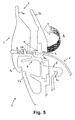
- FIG. 5 Another known embodiment for such a corner connecting portion is shown in Figure 5 which is attached to the present description, in which the upper part 1 of the corner portion 2 has an upper face 3 having upper sealing lips 3a and 3b designed to be mounted under the bodywork, and a lower face 4 differing from that of document EP-A-1 619 060 in that it is provided with a small overmoulded pin 5 designed to protrude into a hole 6a of the pillar 6. As visible in figure 5 , the pin 5 is embedded into a lower zone of the upper part 1 and mutually connects both lips 3 only in this lower face 4.
- the lower part 7 of the corner portion 2 is connected to the upper part 1 so as to surround the pillar outer end 6b and has lower sealing lips 7a and 7b designed to be in contact with the window glass, this lower part 7 also comprising an embedded anchoring hook 8 for fixing the corner portion 2 to a pillar inner end 6c.
- a major drawback of the corner connecting portions according both to this document and to the prior art of figure 5 is that the application point of the force undergone by the corner portion during each door slam, which is located near the upper face of the corner upper part, is thus far above the anchoring point of the corner portion.
- This significant distance between both force application and anchoring points results in a stretching of the rubber material of the corner portion above this anchoring point after each door slam, which may cause after some time the corner portion turn out from its original position (see arrows A and B in figure 5 ) between the corresponding segments of the glass run channel, thus with a possible loss of contact of the sealing gasket with the outer face of the window glass.
- One purpose of the present invention is to provide a corner connecting portion for a sealing gasket of a motor vehicle side window glass which remedies these drawbacks, the gasket forming a window glass run channel of the hidden frame type which comprises a top segment and two ascending segments, the corner portion being designed to connect said top segment to at least one of said ascending segments when mounted on a pillar of the frame, said corner portion comprising:
- said mounting means comprise a pin which is inserted into a corresponding through hole formed in said upper part so as to extend from said upper face to said lower face, said pin being designed to be pushed through an opening of said pillar in an assembly position of the pin, so that the assembled pin minimizes the displacements of the gasket in response to ageing and fatigue cycles of this corner portion due to slams of a door provided with this gasket.
- such a pin to be mounted through the pillar thus extends throughout the most stressed area of the corner portion during each door slam, namely that which undergoes the closing force of the door, so that the glass run channel may not be affected by the ageing and fatigue cycles of the stressed rubber of the corner portion and lastingly remains in its needed functional position as regards the window glass, the pillar and the bodywork of the vehicle.
- the mounting pin of the invention is separately inserted into said beforehand-shaped through hole, so as to occupy several positions throughout the latter including said assembly position where the pin partially goes beneath said lower face of the upper part and at least another preassembly position, as will be explained below. In this assembly position, this pin shall be sealingly in contact with the wall of said through hole.
- outer end and inner end of the pillar it is meant in instant description laterally outer and inner ends, in the Y lateral direction of the width of the vehicle.
- said pin may be a taper pin of either polygonal of circular cross-section, and said hole being formed during moulding of the corner portion.
- said pin may be made of a more or less rigid plastic or elastomeric material or of a combination thereof, the remaining of the corner portion being preferably made of an injection moulded elastomeric composition based on at least one elastomer which may be either a usual rubber such as an EPDM, or a thermoplastic elastomer (TPE) such as a thermoplastic vulcanizate (TPV) or a styrene-ethylene-butylene-styrene copolymer (SEBS).
- a usual rubber such as an EPDM
- TPE thermoplastic elastomer
- TPV thermoplastic vulcanizate
- SEBS styrene-ethylene-butylene-styrene copolymer
- Said pin may be independent from the remaining of the corner portion, being separately inserted into said through hole.
- said pin may advantageously be connected to the remaining of the corner portion by a connecting means such as an attachment thread or string, which is initially placed inside the injection mould with the attached pin being offset therein and upon which said elastomeric composition is overmoulded, so that the pin remains connected to the corner portion prior to be inserted into the through hole and is thus not able to be lost.
- inventive corner portion could be extruded and then cut according to the desired format, instead of being injection moulded.
- said hole may have a symmetry axis which is substantially perpendicular to said lower face (i.e. a substantially vertical axis) and which preferably makes an angle of between 5 and 20° with the Z vertical direction in such a manner that this axis extends towards both the lower part and the inside of the corner portion in the Y lateral direction thereof.
- said pin is also able to occupy a preassembly position where it has a tapered free end which is substantially flush with said lower face of the corner upper part, before to be brought to said assembly position by a pushing force exerted on an opposite pushing end of the pin, so that said free end goes beyond said lower face.
- said pin may be provided with preassembly helping means, such as gripping teeth or fins, that are formed in a preassembly part of the pin which is adjacent said pushing end, these preassembly helping means being able to limit the penetration of the pin through said hole and also preferably to prevent an undesirable withdrawal of the pin from said assembly position.
- preassembly helping means such as gripping teeth or fins
- the assembly of the pin can be done either by the sealing gasket manufacturer or by the customer assembly line, on receiving the gasket with each corner connecting portion including said pin in a retracted preassembly position.
- said pin may have a substantially rectangular cross-section, said preassembly part being provided with teeth or fins on at least two opposite faces thereof which are designed to be in frictional contact with the wall of said hole, the pin having an assembly part adjacent said free end which may extend in a tapered manner from a widening shoulder formed between both parts.
- said pushing end of the pin may be provided with a pushing head substantially forming a "T" with said preassembly and assembly parts.
- said pin may have a substantially circular cross-section and may have an assembly part adjacent said free end which is provided with circumferential ribs, said pin being continuously tapered.
- said corner lower part may comprise anchoring means designed to cooperate with said pillar for the fixation of the corner portion thereto.
- Said anchoring means may advantageously comprise a hook which is embedded in said lower part of the corner portion, preferably by overmoulding, and which is designed to be hooked on an inner end of said pillar.
- said upper face of its upper part may be defined by two sealing lips which are designed to be mounted under and in contact with the vehicle bodywork and which are connected together by the wall of said hole, and said lower part of this corner portion may comprise at least two other sealing lips which are designed to be in contact with the window glass.
- the corner connecting portion may have in side view substantially an arrows shape, having an arrow point defined by said corner upper part, and a shaft ending with a fletching both defined by said corner lower part.
- a sealing gasket for a motor vehicle window glass forms a side window glass run channel of the hidden frame type which comprises a top segment and two ascending segments, this gasket comprising a co-extruded mounting clip of U-shaped right section with first and second mutually parallel limbs, the first limb having first sealing lips which are designed to be mounted under and in contact with the vehicle bodywork, the second limb being provided with a main leg and a secondary leg which both extend perpendicularly from this second limb and which have sealing lips towards their respective ends, this glass run channel incorporating at least one corner connecting portion designed to connect said top segment to one of said ascending segments when mounted on a pillar of the frame.
- This sealing gasket of the invention is characterized in that said at least one corner portion is as defined above.
- a sealing system according to the invention for a motor vehicle side window glass comprises a frame and such a sealing gasket, and it is characterized in that this sealing gasket is mounted on a A-pillar and/or a B-pillar and/or a C-pillar of the vehicle, being preferably mounted on a visible B-pillar or C-pillar.
- visible pillar it is meant as commonly known by the man of the art that the bodywork frame (i.e. the bodyside or bodycase) is visible from the outside of the vehicle, contrary to the door frame which of course remains invisible because of the sealing gasket mounted thereon.
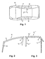
- FIG 1 a vehicle 10 whose front and rear side windows 11 and 12 extend in three different directions X, Y and Z (respectively representing the length, width and height direction of the vehicle 10) and which are each designed to receive a side window sealing gasket according to the invention.
- Each sealing gasket comprises a glass run channel 13, 13' of the hidden frame type (see figures 2 and 3 ) which is usually defined by a top segment 14, 14' connected to two ascending segments 15 and 16, 15' and 16' (i.e. substantially vertical segments) by respective corner connecting portions 17.
- At least one of these corner portions 17 is to be mounted:
- the top segment 14 of the glass run channel 13 of the hidden frame type which is shown in figure 4 comprises a mounting clip or clamping carrier 18 of U-shaped right section in which there is embedded metal reinforcement 19 also of U-shaped right section, two asymmetrical legs 20 and 21 constituting respectively a main leg and a secondary leg which project at substantially 90° from one of the limbs 18a of the mounting clip 18 and which terminate in sealing lips 22 suitable for coming into sliding contact with both faces of the window glass 11 or 12.
- the other limb 18b of the mounting clip 18 supports sealing lips 23 suitable for coming into contact with the bodywork of the vehicle 10.
- the corner connecting portion 17 connects together such a top segment 14 or 14' and an ascending segment 15, 16 or 15', 16' of the glass run channel 13, 13'.
- the corner portion 17 may have substantially an arrows shape, having an arrow point 17a defined by a corner upper part 24 and a shaft 17b ending with a fletching 17c, the shaft 17b and the fletching 17c defining together a corner lower part 28 (both upper and lower parts 24, 26 of the inventive corner portion 17 are shown in figure 6 ).
- the corner portion 17 is preferably obtained by injection moulding and comprises:
- the through hole 24a may be pre-formed during the injection moulding process, and has a symmetry axis Z' which is substantially perpendicular to the lower face by preferably making an angle ⁇ of between 5 and 20° with the vertical direction Z in such a manner that this axis Z' extends towards both the lower part 28 and the inside in the Y direction.
- the pin 27, 27' is designed to be pushed (downwards in the Z direction) through the pillar opening 30a into an assembly position, so that the assembled pin 27, 27', 27" minimizes the displacements of the whole glass run channel 13, 13' in response to ageing and fatigue cycles of the corner portion 17 after a number of slams of the corresponding door.
- This pin 27, 27', 27" is made of a rigid plastic material, such as PA 6.6 (polyamide 6.6), and the remaining of the corner portion 17 is preferably made of an injection moulded elastomeric composition for instance based on an EPDM, a TPV or a SEBS.
- PA 6.6 polyamide 6.6
- the taper pin 27, the through hole 24a and the corresponding pillar opening 30a may be of rectangular cross-section, in such a manner that a small peripheral gap of about 1 or 2 mm be provided between the opening 30a and the pin free end 27a.
- the pin 27 is provided with preassembly helping means comprising gripping fins 27b that are formed in an outer preassembly part 27c ("outer” means “upper” in the Z direction, considering figures 10 and 11 ) of the pin 27, this fins 27b being adjacent a pin pushing end 27d opposite to its free end 27a and being located on two opposite faces of this preassembly part 27c.
- gripping fins 27 are suitable to limit the penetration of the pin 27 through the hole 24a in the preassembly position of figure 10 , by frictional contact with the wall of this hole 24a and also to prevent its undesirable withdrawal from the assembly position of figure 11 (i.e. upwards in the Z direction).
- the pin has an assembly part 27e which includes its free end 27a and which extends in a tapered manner (e.g. in a frustum pyramidal shape) from a widening shoulder 27f formed between the preassembly and assembly parts 27c and 27e, and each fin 27b obliquely extends towards the pin pushing end 27d (i.e. opposite to the downwards pushing direction) from the corresponding face of the preassembly part 27c.
- a tapered manner e.g. in a frustum pyramidal shape
- each fin 27b obliquely extends towards the pin pushing end 27d (i.e. opposite to the downwards pushing direction) from the corresponding face of the preassembly part 27c.
- said pushing end of the pin 27' may be provided with a pushing head 27d' substantially forming a "T" with the preassembly (to allow a better push) and assembly parts 27c and 27e.
- a couple of upper fins 27b' i.e. which are the most adjacent this pushing head 27d'
- these upper fins 27b' mainly allowing to account that the positioning of the pin 27' inside the hole 24a is not too deep.
- the illustrated transverse dimensions of the different faces of the pin 27' may be the following:
- the pin 27" may also be of circular cross-section, having for instance a substantially frustum conical shape between its outer pushing end 27d" and its inner free end 27a", also with preassembly helping means 27b" consisting in this example of circumferential ribs.
- the inventive pin could be used for the inventive pin to make it cooperate in a frictional way with the internal wall of the hole 24a (which may be either cylindrical or prismatic), so that the either frustum conical or frustum pyramidal form of the taper pin deforms this hole wall into a tapered one, as visible in figures 10 and 11 .
- the pin free end 27a is substantially flush with the lower face 26 of the corner upper part 24, before to be brought to the assembly position of figure 11 by a pushing force F exerted on the opposite pin pushing end 27d', so that the pin free end 27a goes beyond this lower face 26 and thus wedges the corner portion 17 without any risk of displacement of the latter and of the whole glass run channel 13, 13' after a number of door slams, due to the fact that the pin 27' extends during each door slam throughout the most stressed area of the corner portion 17.
Landscapes
- Engineering & Computer Science (AREA)
- Mechanical Engineering (AREA)
- Seal Device For Vehicle (AREA)
Abstract
The present invention relates to a corner connecting portion for a sealing gasket of a motor vehicle window glass, the gasket forming a window glass run channel of the hidden frame type.
This corner connecting portion (17) is designed to connect a top segment to an ascending segment of the glass run channel, and it comprises:
- an upper part (24) comprising an upper face designed to be sealingly mounted under the vehicle bodywork and a lower face (26) designed to be mounted on said pillar by mounting means, and
- a lower part (28) which is connected to the upper part by forming a "c" designed to surround an outer end (30b) of said pillar and which is designed to be sealingly in contact with the window glass.
- an upper part (24) comprising an upper face designed to be sealingly mounted under the vehicle bodywork and a lower face (26) designed to be mounted on said pillar by mounting means, and
- a lower part (28) which is connected to the upper part by forming a "c" designed to surround an outer end (30b) of said pillar and which is designed to be sealingly in contact with the window glass.
Said mounting means comprise a pin (27') which is inserted into a corresponding through hole (24a) formed in the upper part so as to extend from the upper face to the lower face, the pin being pushed through a pillar opening (30a) in an assembly position, to minimize the displacements of the gasket in response to ageing and fatigue cycles due to slams of the door.
Description
- The present invention relates to a corner connecting portion for a sealing gasket of a motor vehicle window glass, the gasket forming a window glass run channel of the hidden frame type. The invention also concerns such a sealing gasket incorporating it, and a sealing system for a motor vehicle window glass comprising a frame and this sealing gasket, in particular for a partially or fully stamped door.
- A side window glass run channel of the hidden frame type is generally defined by a top or horizontal extruded segment connected to two ascending or vertical also extruded segments, and it usually comprises a co-extruded mounting clip of U-shaped right section with first and second mutually parallel limbs (this mounting or clamping clip is often called "carrier" by the man of the art), the first limb having first sealing lips which are designed to be mounted under and in contact with the vehicle bodywork, whereas the second limb is provided with two main secondary legs which both extend perpendicularly from this second limb and which have sealing lips towards their ends. The top segment is connected in a known manner to both ascending segments by two injection moulded corner portions which each comprise an upper part mounted on a pillar of the frame and designed to be sealingly mounted under the vehicle bodywork and a lower part surrounding this pillar and designed to be sealingly in contact with the window glass of the corresponding door.
- It is known by document
EP-A-1 619 060 to design such a corner connecting portion which is injection moulded and which comprises: - an upper part with an upper face designed to be sealingly mounted under the vehicle bodywork and a lower face designed to be mounted on the pillar, and
- a lower part which is connected to the upper part so as to surround a pillar outer end and which is designed to be sealingly in contact with the window glass, this lower part comprising embedded anchoring means made of a hook designed to fix the corner portion to a pillar inner end.
- Another known embodiment for such a corner connecting portion is shown in
Figure 5 which is attached to the present description, in which theupper part 1 of thecorner portion 2 has anupper face 3 having upper sealing lips 3a and 3b designed to be mounted under the bodywork, and a lower face 4 differing from that of documentEP-A-1 619 060 in that it is provided with a smallovermoulded pin 5 designed to protrude into a hole 6a of the pillar 6. As visible infigure 5 , thepin 5 is embedded into a lower zone of theupper part 1 and mutually connects bothlips 3 only in this lower face 4. As for the lower part 7 of thecorner portion 2, it is connected to theupper part 1 so as to surround the pillar outer end 6b and has lower sealing lips 7a and 7b designed to be in contact with the window glass, this lower part 7 also comprising an embedded anchoring hook 8 for fixing thecorner portion 2 to a pillar inner end 6c. - A major drawback of the corner connecting portions according both to this document and to the prior art of
figure 5 is that the application point of the force undergone by the corner portion during each door slam, which is located near the upper face of the corner upper part, is thus far above the anchoring point of the corner portion. This significant distance between both force application and anchoring points results in a stretching of the rubber material of the corner portion above this anchoring point after each door slam, which may cause after some time the corner portion turn out from its original position (see arrows A and B infigure 5 ) between the corresponding segments of the glass run channel, thus with a possible loss of contact of the sealing gasket with the outer face of the window glass. - As a consequence of the glass run channel moving from its nominal position after ageing and door closing cycles to a non-functional position on the door frame, it is also to be mentioned that the lips designed to be sealingly mounted under the vehicle bodywork may assure no satisfactory contact with the latter. Moreover, such displacements of the connecting corner portions and of the whole window sealing gasket may thus result at length in a bad acoustic performance for the vehicle.
- One purpose of the present invention is to provide a corner connecting portion for a sealing gasket of a motor vehicle side window glass which remedies these drawbacks, the gasket forming a window glass run channel of the hidden frame type which comprises a top segment and two ascending segments, the corner portion being designed to connect said top segment to at least one of said ascending segments when mounted on a pillar of the frame, said corner portion comprising:
- a corner upper part comprising an upper face designed to be sealingly mounted under the vehicle bodywork and a lower face designed to be mounted on said pillar by mounting means, and
- a corner lower part which is connected to said upper part by substantially forming a "⊂" designed to surround an outer end of said pillar and which is designed to be sealingly in contact with the window glass.
- For this purpose, said mounting means comprise a pin which is inserted into a corresponding through hole formed in said upper part so as to extend from said upper face to said lower face, said pin being designed to be pushed through an opening of said pillar in an assembly position of the pin, so that the assembled pin minimizes the displacements of the gasket in response to ageing and fatigue cycles of this corner portion due to slams of a door provided with this gasket.
- It is to be noted that such a pin to be mounted through the pillar thus extends throughout the most stressed area of the corner portion during each door slam, namely that which undergoes the closing force of the door, so that the glass run channel may not be affected by the ageing and fatigue cycles of the stressed rubber of the corner portion and lastingly remains in its needed functional position as regards the window glass, the pillar and the bodywork of the vehicle.
- It will also be noted that the mounting pin of the invention is separately inserted into said beforehand-shaped through hole, so as to occupy several positions throughout the latter including said assembly position where the pin partially goes beneath said lower face of the upper part and at least another preassembly position, as will be explained below. In this assembly position, this pin shall be sealingly in contact with the wall of said through hole.
- By "outer end" and "inner end" of the pillar, it is meant in instant description laterally outer and inner ends, in the Y lateral direction of the width of the vehicle.
- According to another feature of the invention, said pin may be a taper pin of either polygonal of circular cross-section, and said hole being formed during moulding of the corner portion.
- Advantageously, said pin may be made of a more or less rigid plastic or elastomeric material or of a combination thereof, the remaining of the corner portion being preferably made of an injection moulded elastomeric composition based on at least one elastomer which may be either a usual rubber such as an EPDM, or a thermoplastic elastomer (TPE) such as a thermoplastic vulcanizate (TPV) or a styrene-ethylene-butylene-styrene copolymer (SEBS).
- Said pin may be independent from the remaining of the corner portion, being separately inserted into said through hole. In a variant embodiment, said pin may advantageously be connected to the remaining of the corner portion by a connecting means such as an attachment thread or string, which is initially placed inside the injection mould with the attached pin being offset therein and upon which said elastomeric composition is overmoulded, so that the pin remains connected to the corner portion prior to be inserted into the through hole and is thus not able to be lost.
- Alternatively, the inventive corner portion could be extruded and then cut according to the desired format, instead of being injection moulded.
- According to another feature of the invention, said hole may have a symmetry axis which is substantially perpendicular to said lower face (i.e. a substantially vertical axis) and which preferably makes an angle of between 5 and 20° with the Z vertical direction in such a manner that this axis extends towards both the lower part and the inside of the corner portion in the Y lateral direction thereof.
- Advantageously and as mentioned above, said pin is also able to occupy a preassembly position where it has a tapered free end which is substantially flush with said lower face of the corner upper part, before to be brought to said assembly position by a pushing force exerted on an opposite pushing end of the pin, so that said free end goes beyond said lower face.
- According to another feature of the invention, said pin may be provided with preassembly helping means, such as gripping teeth or fins, that are formed in a preassembly part of the pin which is adjacent said pushing end, these preassembly helping means being able to limit the penetration of the pin through said hole and also preferably to prevent an undesirable withdrawal of the pin from said assembly position.
- It will be noted that the assembly of the pin can be done either by the sealing gasket manufacturer or by the customer assembly line, on receiving the gasket with each corner connecting portion including said pin in a retracted preassembly position.
- In a first embodiment of the invention, said pin may have a substantially rectangular cross-section, said preassembly part being provided with teeth or fins on at least two opposite faces thereof which are designed to be in frictional contact with the wall of said hole, the pin having an assembly part adjacent said free end which may extend in a tapered manner from a widening shoulder formed between both parts.
- According to this first embodiment, said pushing end of the pin may be provided with a pushing head substantially forming a "T" with said preassembly and assembly parts.
- In a second embodiment of the invention, said pin may have a substantially circular cross-section and may have an assembly part adjacent said free end which is provided with circumferential ribs, said pin being continuously tapered.
- According to another feature of the invention, said corner lower part may comprise anchoring means designed to cooperate with said pillar for the fixation of the corner portion thereto. Said anchoring means may advantageously comprise a hook which is embedded in said lower part of the corner portion, preferably by overmoulding, and which is designed to be hooked on an inner end of said pillar.
- According to another feature of the invention, said upper face of its upper part may be defined by two sealing lips which are designed to be mounted under and in contact with the vehicle bodywork and which are connected together by the wall of said hole, and said lower part of this corner portion may comprise at least two other sealing lips which are designed to be in contact with the window glass.
- According to another feature of the invention, the corner connecting portion may have in side view substantially an arrows shape, having an arrow point defined by said corner upper part, and a shaft ending with a fletching both defined by said corner lower part.
- A sealing gasket for a motor vehicle window glass according to the invention forms a side window glass run channel of the hidden frame type which comprises a top segment and two ascending segments, this gasket comprising a co-extruded mounting clip of U-shaped right section with first and second mutually parallel limbs, the first limb having first sealing lips which are designed to be mounted under and in contact with the vehicle bodywork, the second limb being provided with a main leg and a secondary leg which both extend perpendicularly from this second limb and which have sealing lips towards their respective ends, this glass run channel incorporating at least one corner connecting portion designed to connect said top segment to one of said ascending segments when mounted on a pillar of the frame.
- This sealing gasket of the invention is characterized in that said at least one corner portion is as defined above.
- A sealing system according to the invention for a motor vehicle side window glass comprises a frame and such a sealing gasket, and it is characterized in that this sealing gasket is mounted on a A-pillar and/or a B-pillar and/or a C-pillar of the vehicle, being preferably mounted on a visible B-pillar or C-pillar. By "visible pillar", it is meant as commonly known by the man of the art that the bodywork frame (i.e. the bodyside or bodycase) is visible from the outside of the vehicle, contrary to the door frame which of course remains invisible because of the sealing gasket mounted thereon.
- The above-mentioned characteristics of the present invention, along with others, will be understood more clearly on reading the following description of several examples of the invention, which are given for illustrative purposes and are not intended to limit the invention, said description referring to the attached drawings, wherein:
-
figure 1 is a top view of a vehicle having doors whose side windows extend in three different directions and which are each designed to receive a sealing gasket according to the invention, -
figures 2 and 3 are diagrammatic side views of two glass run channels according to the invention, respectively for the front door and the rear door of the vehicle offigure 1 , -
figure 4 is a section view of a sealing gasket forming a top segment of a glass run channel of the hidden frame type according to an example of the invention, -
figure 4a is a side view of a corner connecting portion of the invention which connects a top segment according tofigure 4 and an ascending segment of a glass run channel according to eitherfigure 2 or 3 , -
figure 5 is a lateral section view, taken along the V-V section line offigure 4a , of a corner connecting portion according to the prior art, -
figure 6 is a lateral section view, taken along the same section line asfigure 5 , of a corner connecting portion according to the invention which is devoid of its pin to be mounted through the corner upper part, -
figures 7 and 8 are two perspective views respectively showing two first and second embodiments for a pin of the invention to be inserted through the corner upper part and partially through a frame pillar, -
figure 9 is a perspective view at an enlarged scale of an inventive pin according to a variant embodiment of that offigure 7 , and -
figures 10 and 11 are two lateral section views, each taken along the same section line asfigure 5 , of the inventive corner connecting portion according tofigure 6 provided with the pin offigure 9 ,figure 10 showing this pin in dotted lines in a preassembly position whereasfigure 11 shows it also in dotted lines but in an assembly position. - In
figure 1 is shown a vehicle 10 whose front andrear side windows glass run channel 13, 13' of the hidden frame type (seefigures 2 and 3 ) which is usually defined by atop segment 14, 14' connected to twoascending segments corner connecting portions 17. - According to the invention, at least one of these
corner portions 17 is to be mounted: - in the case of a
front side window 11 shown infigure 2 , on a A-pillar and/or on a B-pillar of the vehicle V (thecorner portion 17 being then preferably mounted on the B-pillar as visible infigure 2 ), or - in the case of a
rear side window 12 shown infigure 3 , on a visible B-pillar and/or on a visible C-pillar of the vehicle V. - The
top segment 14 of theglass run channel 13 of the hidden frame type which is shown infigure 4 comprises a mounting clip or clamping carrier 18 of U-shaped right section in which there is embeddedmetal reinforcement 19 also of U-shaped right section, twoasymmetrical legs lips 22 suitable for coming into sliding contact with both faces of thewindow glass lips 23 suitable for coming into contact with the bodywork of the vehicle 10. - The
corner connecting portion 17 according to an embodiment of the invention which is shown inFigure 4a connects together such atop segment 14 or 14' and anascending segment glass run channel 13, 13'. As visible infigure 4a , thecorner portion 17 may have substantially an arrows shape, having an arrow point 17a defined by a cornerupper part 24 and a shaft 17b ending with a fletching 17c, the shaft 17b and the fletching 17c defining together a corner lower part 28 (both upper andlower parts inventive corner portion 17 are shown infigure 6 ). - As visible in
figure 6 , thecorner portion 17 is preferably obtained by injection moulding and comprises: - the corner
upper part 24 having anupper face 25 defined by twosealing lips 25a and 25b suitable for coming into contact under the vehicle bodywork, and alower face 26 designed to be mounted on a pillar 30 (e.g. a metallic B-pillar) by apin figures 7-11 ) which is subsequently inserted into a throughhole 24a extending from theupper face 25 to thelower face 26 betweenlips 25a and 25b and which is designed to protrude below anopposite opening 30a of thepillar 30 so as to wedge thisupper part 24 on thepillar 30 in the lateral direction Y, and - the corner
lower part 28 which is connected to theupper part 24 by forming a "⊂" designed to surround a lateralouter end 30b of thepillar 30 and which has several sealing lips 28a to 28d suitable for coming into contact with thewindow glass lower part 28 further having anovermoulded hook 29 designed to cooperate with a lateralinner end 30c of thepillar 30 for the anchoring of thecorner portion 17 thereto. - More specifically, the
through hole 24a may be pre-formed during the injection moulding process, and has a symmetry axis Z' which is substantially perpendicular to the lower face by preferably making an angle α of between 5 and 20° with the vertical direction Z in such a manner that this axis Z' extends towards both thelower part 28 and the inside in the Y direction. As will be explained below, thepin 27, 27' is designed to be pushed (downwards in the Z direction) through the pillar opening 30a into an assembly position, so that the assembledpin glass run channel 13, 13' in response to ageing and fatigue cycles of thecorner portion 17 after a number of slams of the corresponding door. Thispin corner portion 17 is preferably made of an injection moulded elastomeric composition for instance based on an EPDM, a TPV or a SEBS. - As visible in the first embodiment of
figure 7 , thetaper pin 27, the throughhole 24a and the corresponding pillar opening 30a may be of rectangular cross-section, in such a manner that a small peripheral gap of about 1 or 2 mm be provided between theopening 30a and the pinfree end 27a. Thepin 27 is provided with preassembly helping means comprisinggripping fins 27b that are formed in an outerpreassembly part 27c ("outer" means "upper" in the Z direction, consideringfigures 10 and 11 ) of thepin 27, thisfins 27b being adjacent apin pushing end 27d opposite to itsfree end 27a and being located on two opposite faces of thispreassembly part 27c. Thesegripping fins 27 are suitable to limit the penetration of thepin 27 through thehole 24a in the preassembly position offigure 10 , by frictional contact with the wall of thishole 24a and also to prevent its undesirable withdrawal from the assembly position offigure 11 (i.e. upwards in the Z direction). - More specifically, the pin has an
assembly part 27e which includes itsfree end 27a and which extends in a tapered manner (e.g. in a frustum pyramidal shape) from a wideningshoulder 27f formed between the preassembly andassembly parts fin 27b obliquely extends towards thepin pushing end 27d (i.e. opposite to the downwards pushing direction) from the corresponding face of thepreassembly part 27c. - As visible in the variant embodiment of
figure 9 , said pushing end of the pin 27' may be provided with a pushinghead 27d' substantially forming a "T" with the preassembly (to allow a better push) andassembly parts upper fins 27b' (i.e. which are the most adjacent this pushinghead 27d') are longer than theother fins 27b in the Y direction, theseupper fins 27b' mainly allowing to account that the positioning of the pin 27' inside thehole 24a is not too deep. Only by way of example, the illustrated transverse dimensions of the different faces of the pin 27' may be the following: - a = 6 mm (maximum cross-width of the
preassembly part 27c in the Y direction, from oneupper fin 27b' to the other one), - b = 5.4 mm (cross-width of the
preassembly part 27c in the Y direction, from onelower fin 27b to the other one), - c = 5 mm (cross-width of the pin
free end 27a in the Y direction), and - d = 2 mm (depth of the pin
free end 27a in the X direction). - As shown in the second embodiment of
figure 8 , thepin 27" may also be of circular cross-section, having for instance a substantially frustum conical shape between its outer pushingend 27d" and its innerfree end 27a", also with preassembly helping means 27b" consisting in this example of circumferential ribs. - It will be noted that other shapes could be used for the inventive pin to make it cooperate in a frictional way with the internal wall of the
hole 24a (which may be either cylindrical or prismatic), so that the either frustum conical or frustum pyramidal form of the taper pin deforms this hole wall into a tapered one, as visible infigures 10 and 11 . - In the preassembly position of
figure 10 , the pinfree end 27a is substantially flush with thelower face 26 of the cornerupper part 24, before to be brought to the assembly position offigure 11 by a pushing force F exerted on the oppositepin pushing end 27d', so that the pinfree end 27a goes beyond thislower face 26 and thus wedges thecorner portion 17 without any risk of displacement of the latter and of the wholeglass run channel 13, 13' after a number of door slams, due to the fact that the pin 27' extends during each door slam throughout the most stressed area of thecorner portion 17.
Claims (17)
- A corner connecting portion (17) for a sealing gasket of a motor vehicle side window glass (11, 12), the gasket forming a window glass run channel (13, 13') of the hidden frame type which comprises a top segment (14, 14') and two ascending segments (15 and 16, 15' and 16'), the corner portion being designed to connect said top segment to at least one of said ascending segments when mounted on a pillar (30) of the frame, this corner portion comprising:- a corner upper part (24) comprising an upper face (25) designed to be sealingly mounted under the vehicle bodywork and a lower face (26) designed to be mounted on said pillar by mounting means, and- a corner lower part (28) which is connected to said upper part by substantially forming a "⊂" designed to surround an outer end (30b) of said pillar and which is designed to be sealingly in contact with the window glass,characterized in that said mounting means comprise a pin (27, 27', 27") which is inserted into a corresponding through hole (24a) formed in said upper part so as to extend from said upper face to said lower face, said pin being designed to be pushed through an opening (30a) of said pillar in an assembly position of the pin, so that the assembled pin minimizes the displacements of the gasket in response to ageing and fatigue cycles of this corner portion due to slams of a door provided with this gasket.
- A corner connecting portion (17) according to claim 1, wherein said pin (27, 27', 27") is a taper pin of either polygonal of circular cross-section, said hole (24a) being formed during moulding of the corner portion.
- A corner connecting portion (17) according to claim 2, wherein said pin (27, 27', 27") is made of a plastic or elastomeric material or of a combination thereof, the remaining of the corner portion being preferably made of an injection moulded elastomeric composition.
- A corner connecting portion (17) according to any of claims 1 to 3, wherein said pin (27, 27', 27") is independent from the remaining of the corner portion, being separately inserted into said through hole (24a).
- A corner connecting portion (17) according to claim 3, wherein said pin (27, 27', 27") is connected to the remaining of the corner portion by connecting means, such as an attachment thread or string, upon a part of which said elastomeric composition is overmoulded so that the pin remains connected to the corner portion prior to be inserted into said through hole (24a).
- A corner connecting portion (17) according to any of the preceding claims, wherein said hole (24a) has a symmetry axis which is substantially perpendicular to said lower face (26).
- A corner connecting portion (17) according to any of the preceding claims, wherein said pin (27, 27', 27") is also able to occupy a preassembly position where it has a tapered free end (27a, 27a") which is substantially flush with said lower face (26) of the corner upper part (24), before to be brought to said assembly position by a pushing force (F) exerted on an opposite pushing end (27d, 27d', 27d") of the pin, so that said free end goes beyond said lower face.
- A corner connecting portion (17) according to claim 7, wherein said pin (27, 27', 27") is provided with preassembly helping means (27b, 27b', 27b"), such as gripping teeth or fins, that are formed in a preassembly part (27c) of the pin which is adjacent said pushing end (27d, 27d', 27d"), these preassembly helping means being able to limit the penetration of the pin through said hole (24) and also preferably to prevent an undesirable withdrawal of the pin from said assembly position.
- A corner connecting portion (17) according to claim 8, wherein said pin (27, 27') has a substantially rectangular cross-section, said preassembly part (27c) being provided with teeth or fins (27b, 27b') on at least two opposite faces thereof which are designed to be in frictional contact with the wall of said hole (24a), the pin having an assembly part (27e) adjacent said free end (27a) and extending in a tapered manner from a widening shoulder (27f) formed between both parts.
- A corner connecting portion (17) according to claim 9, wherein said pushing end (27d') of the pin (17') is provided with a pushing head substantially forming a "T" with said preassembly and assembly parts (27c and 27e).
- A corner connecting portion (17) according to claim 8, wherein said pin (27") has a substantially circular cross-section and has an assembly part adjacent said free end (27a") which is provided with circumferential ribs (27b"), said pin being continuously tapered.
- A corner connecting portion (17) according to any of the preceding claims, wherein said corner lower part (28) comprises anchoring means (29) designed to cooperate with said pillar (30) for the fixation of the corner portion thereto.
- A corner connecting portion (17) according to claim 12, wherein said anchoring means comprise a hook (29) which is embedded in said lower part (28) preferably by overmoulding, and which is designed to be hooked on an inner end (30c) of said pillar (30).
- A corner connecting portion (17) according to any of the preceding claims, wherein said upper face (25) of its upper part (24) is defined by two sealing lips (25a and 25b) which are designed to be mounted under and in contact with the vehicle bodywork and which are connected together by the wall of said hole (24a), and in that said lower part (28) of this corner portion comprises at least two other sealing lips (28a and 28b) which are designed to be in contact with the window glass (11, 12).
- A corner connecting portion (17) according to any of the preceding claims, wherein it has in side view substantially an arrows shape, having an arrow point (17a) defined by said corner upper part (24), and a shaft (17b) ending with a fletching (17c) both defined by said corner lower part (28).
- A sealing gasket for a motor vehicle window glass (11, 12), the gasket forming a side window glass run channel (13, 13') of the hidden frame type which comprises a top segment (14, 14') and two ascending segments (15 and 16, 15' and 16'), this gasket comprising a co-extruded mounting clip (18) of U-shaped right section with first and second mutually parallel limbs (18a and 18b), the first limb (18b) having first sealing lips (23) which are designed to be mounted under and in contact with the vehicle bodywork, the second limb (18a) being provided with a main leg (20) and a secondary leg (21) which both extend perpendicularly from this second limb and which have sealing lips (22) towards their respective ends, this glass run channel incorporating at least one corner connecting portion (17) designed to connect said top segment to one of said ascending segments when mounted on a pillar (30) of the frame, characterized in that said at least one corner portion is as defined in any of the preceding claims.
- A sealing system for a motor vehicle side window glass (11, 12), comprising a frame and a sealing gasket according to claim 16, characterized in that this sealing gasket is mounted on a A-pillar and/or a B-pillar and/or a C-pillar of the vehicle, being preferably mounted on a visible B-pillar or C-pillar.
Priority Applications (2)
| Application Number | Priority Date | Filing Date | Title |
|---|---|---|---|
| EP08016966A EP2168800A1 (en) | 2008-09-26 | 2008-09-26 | A corner portion for a hidden frame window run, a sealing gasket forming this run and a sealing system incorporating it |
| US12/566,109 US20100077670A1 (en) | 2008-09-26 | 2009-09-24 | Corner portion for a hidden frame window run, a sealing gasket forming this run and a sealing system incorporating it |
Applications Claiming Priority (1)
| Application Number | Priority Date | Filing Date | Title |
|---|---|---|---|
| EP08016966A EP2168800A1 (en) | 2008-09-26 | 2008-09-26 | A corner portion for a hidden frame window run, a sealing gasket forming this run and a sealing system incorporating it |
Publications (1)
| Publication Number | Publication Date |
|---|---|
| EP2168800A1 true EP2168800A1 (en) | 2010-03-31 |
Family
ID=40042528
Family Applications (1)
| Application Number | Title | Priority Date | Filing Date |
|---|---|---|---|
| EP08016966A Withdrawn EP2168800A1 (en) | 2008-09-26 | 2008-09-26 | A corner portion for a hidden frame window run, a sealing gasket forming this run and a sealing system incorporating it |
Country Status (2)
| Country | Link |
|---|---|
| US (1) | US20100077670A1 (en) |
| EP (1) | EP2168800A1 (en) |
Cited By (2)
| Publication number | Priority date | Publication date | Assignee | Title |
|---|---|---|---|---|
| EP2223818A3 (en) * | 2009-02-27 | 2011-09-21 | Volkswagen Aktiengesellschaft | Device and method for mounting an elastic rubber seal profile and fastening element for fastening the seal profile |
| CN111301130A (en) * | 2019-11-18 | 2020-06-19 | 浙江零跑科技有限公司 | A frameless door sealing structure |
Families Citing this family (11)
| Publication number | Priority date | Publication date | Assignee | Title |
|---|---|---|---|---|
| DE102013101896A1 (en) * | 2013-02-26 | 2014-08-28 | Bayerische Motoren Werke Aktiengesellschaft | weatherstrip |
| US9649921B2 (en) * | 2013-09-03 | 2017-05-16 | Tokai Kogyo Co., Ltd. | Run channel |
| US9694660B2 (en) * | 2015-06-03 | 2017-07-04 | Nishikawa Rubber Co., Ltd. | Glass run |
| DE102015210829B4 (en) * | 2015-06-12 | 2025-12-04 | Bayerische Motoren Werke Aktiengesellschaft | Sealing arrangement for a side door of a motor vehicle |
| JP6760741B2 (en) * | 2016-03-08 | 2020-09-23 | 西川ゴム工業株式会社 | Glass run for car doors |
| JP6781037B2 (en) * | 2016-04-12 | 2020-11-04 | 西川ゴム工業株式会社 | Vehicle door glass run |
| US10569629B2 (en) * | 2016-04-12 | 2020-02-25 | Nishikawa Rubber Co., Ltd. | Glass run for automobile door |
| FR3078657B1 (en) * | 2018-03-12 | 2020-03-20 | Compagnie Plastic Omnium | OPTIMIZED TAILGATE AMOUNTS |
| USD930536S1 (en) * | 2019-07-12 | 2021-09-14 | Jinhao Guo | Weatherstrip for car door |
| CN111597743B (en) * | 2020-04-20 | 2023-05-23 | 中国第一汽车股份有限公司 | Durability analysis method, device, equipment and storage medium of door switch |
| FR3157279A1 (en) * | 2023-12-22 | 2025-06-27 | Hutchinson | SLIDE FOR A MOVABLE WINDOW FRAME OF A VEHICLE AND METHOD FOR MANUFACTURING SAME |
Citations (7)
| Publication number | Priority date | Publication date | Assignee | Title |
|---|---|---|---|---|
| DE8431541U1 (en) * | 1984-10-26 | 1985-05-15 | Metzeler Kautschuk GmbH, 8000 München | Door seal for an oven |
| FR2642809A1 (en) * | 1989-01-13 | 1990-08-10 | Smadja Jean Claude | Sealing device particularly for motor vehicles including at least one tubular profiled component |
| EP1211116A2 (en) * | 2000-11-24 | 2002-06-05 | METZELER Automotive Profiles GmbH | Sealing profile |
| US20040247827A1 (en) * | 2003-03-28 | 2004-12-09 | Yoshihisa Kubo | Weather strip and manufacturing method therefor |
| EP1619060A2 (en) | 2004-07-22 | 2006-01-25 | Seat, S.A. | Sealing joint between vehicle bodywork components |
| US7010886B2 (en) * | 2003-03-14 | 2006-03-14 | Nishikawa Rubber Co., Ltd. | Fixing structure of a door weather strip |
| US20070028524A1 (en) * | 2005-08-05 | 2007-02-08 | Toyoda Gosei Co., Ltd. | Sealing structure for vehicle door |
Family Cites Families (4)
| Publication number | Priority date | Publication date | Assignee | Title |
|---|---|---|---|---|
| KR100537921B1 (en) * | 1999-08-24 | 2005-12-21 | 니시카와고무고교가부시키가이샤 | Retainerless weather strip |
| JP2004291901A (en) * | 2003-03-28 | 2004-10-21 | Toyoda Gosei Co Ltd | Weather strip |
| JP4254318B2 (en) * | 2003-04-11 | 2009-04-15 | 豊田合成株式会社 | Door weather strip |
| US8667737B2 (en) * | 2006-07-26 | 2014-03-11 | Honda Motor Co., Ltd | Weather seal for a vehicle door |
-
2008
- 2008-09-26 EP EP08016966A patent/EP2168800A1/en not_active Withdrawn
-
2009
- 2009-09-24 US US12/566,109 patent/US20100077670A1/en not_active Abandoned
Patent Citations (7)
| Publication number | Priority date | Publication date | Assignee | Title |
|---|---|---|---|---|
| DE8431541U1 (en) * | 1984-10-26 | 1985-05-15 | Metzeler Kautschuk GmbH, 8000 München | Door seal for an oven |
| FR2642809A1 (en) * | 1989-01-13 | 1990-08-10 | Smadja Jean Claude | Sealing device particularly for motor vehicles including at least one tubular profiled component |
| EP1211116A2 (en) * | 2000-11-24 | 2002-06-05 | METZELER Automotive Profiles GmbH | Sealing profile |
| US7010886B2 (en) * | 2003-03-14 | 2006-03-14 | Nishikawa Rubber Co., Ltd. | Fixing structure of a door weather strip |
| US20040247827A1 (en) * | 2003-03-28 | 2004-12-09 | Yoshihisa Kubo | Weather strip and manufacturing method therefor |
| EP1619060A2 (en) | 2004-07-22 | 2006-01-25 | Seat, S.A. | Sealing joint between vehicle bodywork components |
| US20070028524A1 (en) * | 2005-08-05 | 2007-02-08 | Toyoda Gosei Co., Ltd. | Sealing structure for vehicle door |
Cited By (2)
| Publication number | Priority date | Publication date | Assignee | Title |
|---|---|---|---|---|
| EP2223818A3 (en) * | 2009-02-27 | 2011-09-21 | Volkswagen Aktiengesellschaft | Device and method for mounting an elastic rubber seal profile and fastening element for fastening the seal profile |
| CN111301130A (en) * | 2019-11-18 | 2020-06-19 | 浙江零跑科技有限公司 | A frameless door sealing structure |
Also Published As
| Publication number | Publication date |
|---|---|
| US20100077670A1 (en) | 2010-04-01 |
Similar Documents
| Publication | Publication Date | Title |
|---|---|---|
| EP2168800A1 (en) | A corner portion for a hidden frame window run, a sealing gasket forming this run and a sealing system incorporating it | |
| EP2602139B1 (en) | Glass run channel assembly | |
| EP1838545B1 (en) | Encapsulated fixed window module | |
| US9969250B2 (en) | Sealing member of door for car | |
| KR101952146B1 (en) | Glass panel having an encapsulated profiled joint and insert attached to the joint, element for attaching the insert for the glass panel, and method for manufacturing the glass panel | |
| CA2326871C (en) | Window molding | |
| JP2015506877A (en) | Sealing device for vehicle window, method for manufacturing the sealing device and use thereof | |
| EP2885477B1 (en) | Plastic channel assembly-below belt bracket for glassrun system | |
| JP6566744B2 (en) | Automotive door seals | |
| EP1630024A1 (en) | Ascending/descending door glass support structure | |
| CN111094037A (en) | Easy-to-install window molding profiles | |
| KR20110001926A (en) | Filler with integrated fixing aid | |
| US20170225555A1 (en) | Weatherstrip fixing structure | |
| US20200172024A1 (en) | Weather strip, weather strip attachment structure, and weather strip attachment method | |
| JP2013086767A (en) | Door weatherstrip for vehicle | |
| JP6032434B2 (en) | Weather strip | |
| EP1619060A2 (en) | Sealing joint between vehicle bodywork components | |
| KR100776653B1 (en) | Door frame sealing structure of automobile | |
| JP6584944B2 (en) | Weather strip and weather strip mounting structure | |
| KR20190033308A (en) | Corner cover of door frame | |
| CN113939416A (en) | Exterior weatherstrip with adaptive trim | |
| JP2024152455A (en) | Automotive sealants | |
| JP2021160448A (en) | Inner Weather Strip | |
| JP2010202056A (en) | Mounting structure of door weather strip | |
| KR20060032289A (en) | Door inside belt weather strip for car |
Legal Events
| Date | Code | Title | Description |
|---|---|---|---|
| PUAI | Public reference made under article 153(3) epc to a published international application that has entered the european phase |
Free format text: ORIGINAL CODE: 0009012 |
|
| AK | Designated contracting states |
Kind code of ref document: A1 Designated state(s): AT BE BG CH CY CZ DE DK EE ES FI FR GB GR HR HU IE IS IT LI LT LU LV MC MT NL NO PL PT RO SE SI SK TR |
|
| AX | Request for extension of the european patent |
Extension state: AL BA MK RS |
|
| AKY | No designation fees paid | ||
| REG | Reference to a national code |
Ref country code: DE Ref legal event code: 8566 |
|
| STAA | Information on the status of an ep patent application or granted ep patent |
Free format text: STATUS: THE APPLICATION IS DEEMED TO BE WITHDRAWN |
|
| 18D | Application deemed to be withdrawn |
Effective date: 20101001 |