EP2168727A1 - Substrate conveying arm - Google Patents
Substrate conveying arm Download PDFInfo
- Publication number
- EP2168727A1 EP2168727A1 EP09011925A EP09011925A EP2168727A1 EP 2168727 A1 EP2168727 A1 EP 2168727A1 EP 09011925 A EP09011925 A EP 09011925A EP 09011925 A EP09011925 A EP 09011925A EP 2168727 A1 EP2168727 A1 EP 2168727A1
- Authority
- EP
- European Patent Office
- Prior art keywords
- substrate
- conveying arm
- work stage
- conveying
- suction
- Prior art date
- Legal status (The legal status is an assumption and is not a legal conclusion. Google has not performed a legal analysis and makes no representation as to the accuracy of the status listed.)
- Granted
Links
Images


Classifications
-
- B—PERFORMING OPERATIONS; TRANSPORTING
- B25—HAND TOOLS; PORTABLE POWER-DRIVEN TOOLS; MANIPULATORS
- B25J—MANIPULATORS; CHAMBERS PROVIDED WITH MANIPULATION DEVICES
- B25J15/00—Gripping heads and other end effectors
- B25J15/06—Gripping heads and other end effectors with vacuum or magnetic holding means
- B25J15/0616—Gripping heads and other end effectors with vacuum or magnetic holding means with vacuum
-
- H—ELECTRICITY
- H05—ELECTRIC TECHNIQUES NOT OTHERWISE PROVIDED FOR
- H05K—PRINTED CIRCUITS; CASINGS OR CONSTRUCTIONAL DETAILS OF ELECTRIC APPARATUS; MANUFACTURE OF ASSEMBLAGES OF ELECTRICAL COMPONENTS
- H05K13/00—Apparatus or processes specially adapted for manufacturing or adjusting assemblages of electric components
- H05K13/02—Feeding of components
-
- B—PERFORMING OPERATIONS; TRANSPORTING
- B65—CONVEYING; PACKING; STORING; HANDLING THIN OR FILAMENTARY MATERIAL
- B65G—TRANSPORT OR STORAGE DEVICES, e.g. CONVEYORS FOR LOADING OR TIPPING, SHOP CONVEYOR SYSTEMS OR PNEUMATIC TUBE CONVEYORS
- B65G47/00—Article or material-handling devices associated with conveyors; Methods employing such devices
- B65G47/74—Feeding, transfer, or discharging devices of particular kinds or types
- B65G47/90—Devices for picking-up and depositing articles or materials
- B65G47/91—Devices for picking-up and depositing articles or materials incorporating pneumatic, e.g. suction, grippers
Definitions
- the present invention relates to a substrate conveying arm for conveying a printed board or a glass substrate for a liquid crystal panel while holding it by means of vacuum suction, particularly to the structure of a substrate conveying arm capable of allowing a work stage, which uses vacuum suction, to adsorb and hold it even if the substrate has a bend.
- printed circuit boards and glass substrates used for liquid crystal panels can be conveyed either by a method for scooping and bringing a substrate upward with a conveying arm (e.g., Japanese Laid-open Application No. 4052826 ) or a method for adsorbing and suspending a substrate with multiple pads mounted on a conveying arm (e.g., Japanese Laid-open Application No. 4048464 ).
- a conveying arm e.g., Japanese Laid-open Application No. 4052826
- a method for adsorbing and suspending a substrate with multiple pads mounted on a conveying arm e.g., Japanese Laid-open Application No. 4048464 .
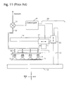
- Fig. 11 is a view showing the configuration of a conveying device provided with a conveying arm for conveying a substrate by suspending it with suction pads.
- the conveying device in Fig. 11 is seen sideways.
- the conveying arm 10 is provided with multiple suction pads 1 for holding a substrate to be conveyed 11 downward.
- the suction pad 1 is mainly constituted of a pad part 2 and an axis part 3.
- the pad part 2 is a portion that comes into contact with a substrate and is made of soft deformable resin.
- the axis part 3 is a portion that fixes the suction arm to the conveying arm, and extends and contracts within the range of several mm.
- a vacuum supply passage is formed inside the axial part.
- an area where the pad part 2 of the suction pad 1 is allowed to attach On the surface of the substrate to be conveyed 11 is formed an area where the pad part 2 of the suction pad 1 is allowed to attach, and the suction pad 1 is mounted on the conveying arm 10 in alignment with the area.
- the area where the suction pad 1 is allowed to attach is often a place between two patterns of a circuit formed on the substrate 11 or a peripheral portion of the substrate where no pattern is formed.
- a vacuum piping is connected to the axis part 3 of each suction pad 1, and a vacuum is supplied at the time of adsorbing and holding the substrate 11.
- a conveying arm moving mechanism 20 is mounted on the conveying arm 10.
- the conveying arm moving mechanism 20 allows moving the substrate 11, which is being held, to a desired position.
- a substrate is held by the conveying arm 10, conveyed to the position above a work stage, mounted on the work stage to be held there by vacuum suction, and then subjected to the exposure treatment.
- the substrate that was subjected to the exposure treatment is adsorbed and held by the conveying arm 10 and conveyed from the work stage to the next step.
- the conveying arm moving mechanism 20 is constituted of an X direction drive part 21 and a Z direction drive part 22 that move the conveying arm in the Z direction (i.e., the vertical direction in the drawing) and the X direction (i.e., the horizontal direction in the drawing) along a Z direction guide 13 and an X direction guide 14, respectively.
- the Z direction guide 13 is mounted on a base plate, and the X direction guide is mounted on the Z direction drive part 22 to be moved in the Z direction.
- a control part 30 not only controls the abovementioned X direction drive part 21 and the Z direction drive part 22 to move the conveying arm to a desired position, but also controls the supply of a vacuum to the suction pad 1 of the conveying arm 10 by driving an electromagnetic valve 31 to regulate the suction, holding and release of the substrate 11 by means of the suction pad 1.
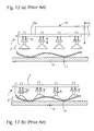
- Fig. 12 shows an enlarged portion of the conveying arm 10 in Fig. 11 .
- a description of the operation of the conveying arm 10 is given below with reference to this drawing.
- the vacuum piping connected to the suction pad 1 is not shown here.
- the suction pad 1 is mainly formed of a pad part 2 and an axis part 3.
- the pad part 2 is a portion that comes into contact with a substrate.
- the pad part 2 is made of soft resin that is deformable to a certain degree.
- the suction pad 1 is mounted on a plate 10a for the conveying arm 10 at the axis part 3.
- a spring 3a is mounted on the axis part 3, and therefore the suction pad 1 is movable in the vertical direction in the drawing (i.e., the Z direction) relative to the plate 10a, on which the suction pad is mounted, within the range of several mm.
- the substrate 11 conveyed by the conveying arm 10 may have a bend.
- a printed circuit board may have a bend as a result of the treatment processing in the previous steps.
- Fig. 12 shows a substrate having a bend (the bend in the drawing is exaggerated because the actual bend of the substrate is only a few mm).
- a vacuum is supplied to the suction pad 1 of the conveying arm 10.
- the conveying arm 10 moves to a location just above the stage 15 on which the substrate 11 is mounted, and then descends.
- the pad part 2 of the suction pad 1 is brought into contact with the substrate 11.
- the position of the axis part 3 changes vertically (i.e., in the Z direction) in a manner of agreeing with the shape of the substrate.
- the shape of the pad 2 also changes because it is soft. Accordingly, the substrate 11 is attached and held by the suction pad 1.
- the conveying arm 10 ascends, and then the substrate 11 is conveyed away from the stage 15.
- the conveying arm 10 is capable of connecting and holding a substrate as a result of the vertical movement of the axis part 3 in agreement with the bend and the change in the shape of the pad part 2 in the suction pad 1 and conveying it.
- any bending of the substrate must be corrected and the substrate made to lie flat along the surface of the stage.
- a conventional conveying arm it may not be possible for a conventional conveying arm to connect to and hold a bent substrate in a flat condition.
- a primary object of the present invention is to correct a bent substrate and make it lie flat along the surface of a work stage by pressing the substrate down toward the work stage at the time of mounting the substrate on the work stage, thereby preventing any leakage of a vacuum used for suction between the substrate and the work stage and allowing the work stage to hold the substrate.
- the present invention provides a substrate conveying arm for conveying a substrate while holding it with a suction pad on the underside thereof and mounting the substrate on a work stage used for holding it with vacuum suction, the substrate conveying arm having the following configuration.
- an elastic member which is shorter than the length of the suction pad, is provided on the side that the suction pad of the substrate conveying arm is provided.
- the elastic member is made shorter than the length of the suction pad and provided above the tip end of the suction pad so that the substrate is unlikely to come off the suction pad at a time when the substrate is conveyed by the substrate conveying arm.
- the substrate is mounted on a work stage, it is pressed down by the elastic member causing the substrate to be made flat.
- the elastic member be mounted at a position where a peripheral portion of a substrate can be pressed toward the work stage side.
- the configuration is such that a substrate can be pressed toward the stage side by means of an elastic member provided on the same side as that of the suction pad at a time when a conveying arm mounts the bent substrate on the work stage.
- the substrate is made flat along the surface of the stage. Accordingly, a gap between the substrate and the stage disappears, which leads to the disappearance of any leakage of a vacuum supplied to the work stage for suctioning of the substrate. As a result, the work stage can hold the substrate.
- Fig. 1 is a view showing the configuration of a conveying device provided with a conveying arm according to an embodiment of the present invention.
- Figs. 2(a) & 2(b) are sectional views taken along line A-A line in Fig. 1 .
- Fig. 3 is a perspective view showing the arrangement of suction pads and flat springs attached to a conveying arm.
- Figs. 4(a) & 4(b) are views for explaining a first operation of the conveying arm according to the present embodiment.
- Figs. 5(a) & 5(b) are views for explaining a second operation of the conveying arm according to the present embodiment.
- Figs. 6(a)-6(c) are views for explaining a third operation of the conveying arm according to the present embodiment.
- Fig. 7 is a view for explaining a fourth operation of the conveying arm according to the present embodiment.
- Fig. 8(a) & 8(b) are views for explaining a fifth operation of the conveying arm according to the present embodiment.
- Fig. 9(a)-9(c) are views showing suction pad variations.
- Fig. 10(a) & 10(b) are views showing other examples for mounting a flat spring and Fig. 10(c) shows an example of using an elastic body other than a flat spring.
- Fig. 11 is a view showing the configuration of a conveying device according to the prior art provided with a conveying arm for conveying a substrate by suspending it with suction pads.
- Fig. 12 is a view for explaining the operation in the prior art of holding a bent substrate with a conveying arm.
- Fig. 1 is a view showing the configuration of a conveying device provided with the conveying arm according to an embodiment of the present invention.
- Fig. 1 differs from Fig. 11 in that multiple flat springs 4 are mounted, as elastic members, on the side of the conveying arm 10 at which the substrate 11 is held.
- the conveying arm 10 is provided with multiple suction pads 1 directed downward that are used for attaching the substrate 11 and made of a pad part 2 and an axis part 3.
- the pad part 2 is made of soft deformable resin, and a vacuum supply passage is formed inside the axis part 3.
- the suction pad 1 is provided at a position corresponding to a peripheral portion of the substrate, for example, as described above, or at a position that corresponds to a place between two patterns of a circuit or the like formed on the substrate 11.
- the conveying arm 10 is mounted on a conveying arm moving mechanism 20.
- the conveying arm moving mechanism 20 allows moving of the substrate 11, which is being held, to a desired location.
- the conveying arm moving mechanism 20 has an X direction drive part 21 and a Z direction drive part 22 for moving the conveying arm 10 along a Z direction guide 13 and an X direction guide 14, for example.
- the configuration may be such that the conveying arm can be moved in the Y direction (i.e., the front and back direction in the drawing) with a Y direction drive and guide.
- a control part 30 not only controls the abovementioned X direction drive part 21 and the Z direction drive part 22 to move the conveying arm to a desired location, but also controls the supply of a vacuum to the suction pad 1 of the conveying arm 10 by driving an electromagnetic valve 31 to regulate the suction, holding and release of the substrate 11 by means of the suction pad 1.
- FIG. 3 is a perspective view showing the arrangement of suction pads and flat springs attached to a conveying arm. In the drawing, a plate on which the alternating sequence of suction pads and flat springs are mounted is shown with a dotted line.
- each suction pad 1 is mounted on a plate 10a of the conveying arm 10 in such a way that it can suck the substrate 11 at a position that where it is allowed to come into contact therewith (i.e., a position where no pattern is formed, such as a peripheral portion).
- the suction pad 1 is movable in the vertical direction (i.e., the Z direction) relative to the plate 10 on which it is mounted within the range of several mm. Also, the suction pad is made of soft resin that is deformable to a certain degree.
- the suction pad 1 according to the present embodiment is a type as shown in Fig. 9(a) .
- Other shapes are also acceptable as far as they are flexible enough to adjust themselves to the deformation of a substrate to a certain degree.
- Other examples of suitable suction pads include one with bellows as shown in Fig. 9(b) and one formed of a sponge as shown in Fig. 9(c) .
- the elastic member can be a flat spring 4 that is mounted on a peripheral portion of the plate 10a of the conveying arm 10. Since the flat spring 4 is brought into contact with the substrate 11 at a time when the substrate 11 is placed on the work stage as described below, the position where the flat spring 4 is provided is also one that is allowed to come into contact with the substrate 11 (i.e., a position where no pattern is formed).
- One end of the flat spring 4 is fixed to a mounting block 4a with a screw 4b, for example.
- the block for mounting the flat spring 4a is fixed to the plate 10a for the conveying arm 10.
- the other end of the flat spring 4 extends to the place where the suction pads 1 are arranged and are open.
- the flat spring 4 is shorter (in the height) than the length of the suction pad 1.
- the free end portion of the flat spring 4 is slightly bent back away from the tip end of the suction pad 1 to prevent the flat spring 4 striking and tearing the substrate off the suction pad 1 when the suction pad 1 attaches and conveys the substrate and the upward pressure is released.
- the actual design is such that there is a gap of about 0.5 mm between the tip end of the flat spring 4 and the substrate at a time when the suction pad 1 holds the substrate.
- a description of the operation of the conveying arm according to the present invention is given below with reference to Figs 4-8 , wherein a substrate is conveyed from a stage on which the substrate is mounted to a work stage having a vacuum suction mechanism, mounted on the work stage, and then is held there by suction.
- a vacuum line connected to the suction pad is not shown in these figures, but is as shown in Fig. 11 .
- the conveying arm 10 is moved to the place just above the stage 15 on which the substrate 11 is mounted and then starts descending. Also, a vacuum is supplied to suction pads 1 mounted on the conveying arm 10
- the position of the suction pads 1 in the vertical direction (i.e., the Z direction) and the shape of the pad part 2 change according to the shape of the substrate 11, and then, the substrate 11 is held by the suction pads 1 under the action of the supplied vacuum.
- Fig. 6(a) is a view of a flat spring 4 as seen sideways at this stage. The substrate 11 and the flat spring 4 have not been brought into contact with each other yet.
- the conveying arm 10 holding the bent substrate 11 starts descending, and part of the bent substrate 11 comes into contact with the surface of the work stage 16, and vacuum is supplied to vacuum suction grooves 16 formed on the surface of the work stage 16.
- Fig. 6(b) is a view of a flat spring 4 as seen sideways on this stage.
- the suction pad 1 moves toward the side of the plate 10a, and then the peripheral portion of the substrate 11 on the upwardly bent side comes into contact with the flat spring 4. Although it tries to push the flat spring 4 upward, the substrate 11 is instead pressed down toward the work stage 16 by the elastic force of the flat spring 4.
- the conveying arm 10 is further brought downward.
- the flat spring 4 further presses the peripheral portion of the substrate on the upwardly bent side down toward the work stage 16.
- the peripheral portion of the substrate 11 is corrected to be made flat along the surface of the work stage 16.
- the conveying arm 10 is brought further downward.
- the peripheral portion of the substrate 11 is pressed down toward the work stage 16 by the flat springs 4 and caused to be made flat along the surface of the work stage 16.
- the gap between the work stage 16 and the substrate 11 disappears, which leads to the disappearance of any leakage of a vacuum supplied to vacuum suction grooves 16a.
- Fig. 8(b) the supply of a vacuum to the suction pads 1 is stopped.
- the conveying arm 10 releases its hold on the substrate 11 and moves upward.
- the structure may be such that air can be supplied to the vacuum line to create a back pressure at the time of releasing the holding of the substrate 11.
- the flat spring 4 used for pressing down the substrate 11 is mounted in such a manner that the substrate 11 is pressed outwardly by the spring 4 which extends outward from the mounting block which is located inward of the suction pad.
- the spring 4 may also be mounted in such a manner that the substrate is pressed inwardly by the spring 4 extending inward from the mounting block which is located outward of the suction pad as shown in Fig. 10(a) .
- a work stage 16 used for holding the substrate 11, wherein a lip seal is mounted on the peripheral portion thereof so that the bent substrate can easily be held by vacuum.
- the position of the substrate 11 to be pressed down by the flat spring 4 is preferably in agreement with the position where the lip seal 16a is provided, as shown in Fig. 10(b) . In this manner, it is easier to prevent a vacuum from leaking from a peripheral portion of the substrate 11.
- the suction pads 1 and the flat springs 4 are provided in an alternating sequence so that the number of the suction pads 1 is nearly the same as the number of the flat springs 4.
- the number of the flat springs 4 may be decreased or increased.
- the level of the force used for correcting a bend i.e., the force used for pressing down the bent substrate toward the work stage
- the position and number of the flat springs 4 (elastic members) provided for the conveying arm 10 can optionally be designed depending on the type of substrate to be conveyed.
- a flat spring is used as an elastic member.
- the elastic member is not limited to a flat spring.
- a coil spring may be used as shown in Fig. 10(c) .
- any other type of elastic member e.g., a block of elastic material, can be used so long as it can produce a force sufficient to press the peripheral portion of a bent substrate down toward a work stage.
- the tip of an elastic member must slightly be above the tip end of a suction pad in the state that no substrate is held so that the elastic member will not push the substrate off the suction pad during conveying of the substrate.
Landscapes
- Engineering & Computer Science (AREA)
- Mechanical Engineering (AREA)
- Robotics (AREA)
- Manufacturing & Machinery (AREA)
- Microelectronics & Electronic Packaging (AREA)
- Manipulator (AREA)
- Container, Conveyance, Adherence, Positioning, Of Wafer (AREA)
- Feeding Of Articles By Means Other Than Belts Or Rollers (AREA)
- Exposure And Positioning Against Photoresist Photosensitive Materials (AREA)
- Sheets, Magazines, And Separation Thereof (AREA)
- Liquid Crystal (AREA)
Abstract
Description
- The present invention relates to a substrate conveying arm for conveying a printed board or a glass substrate for a liquid crystal panel while holding it by means of vacuum suction, particularly to the structure of a substrate conveying arm capable of allowing a work stage, which uses vacuum suction, to adsorb and hold it even if the substrate has a bend.
- In the process for producing printed circuit boards and liquid crystal panels, printed circuit boards and glass substrates used for liquid crystal panels can be conveyed either by a method for scooping and bringing a substrate upward with a conveying arm (e.g., Japanese Laid-open Application No.
4052826 4048464 -
Fig. 11 is a view showing the configuration of a conveying device provided with a conveying arm for conveying a substrate by suspending it with suction pads. The conveying device inFig. 11 is seen sideways. - The conveying
arm 10 is provided withmultiple suction pads 1 for holding a substrate to be conveyed 11 downward. Thesuction pad 1 is mainly constituted of apad part 2 and anaxis part 3. Thepad part 2 is a portion that comes into contact with a substrate and is made of soft deformable resin. Theaxis part 3 is a portion that fixes the suction arm to the conveying arm, and extends and contracts within the range of several mm. A vacuum supply passage is formed inside the axial part. - On the surface of the substrate to be conveyed 11 is formed an area where the
pad part 2 of thesuction pad 1 is allowed to attach, and thesuction pad 1 is mounted on the conveyingarm 10 in alignment with the area. The area where thesuction pad 1 is allowed to attach is often a place between two patterns of a circuit formed on thesubstrate 11 or a peripheral portion of the substrate where no pattern is formed. - A vacuum piping is connected to the
axis part 3 of eachsuction pad 1, and a vacuum is supplied at the time of adsorbing and holding thesubstrate 11. - A conveying
arm moving mechanism 20 is mounted on the conveyingarm 10. The conveyingarm moving mechanism 20 allows moving thesubstrate 11, which is being held, to a desired position. For example, in the case of an exposure device, a substrate is held by the conveyingarm 10, conveyed to the position above a work stage, mounted on the work stage to be held there by vacuum suction, and then subjected to the exposure treatment. - After the exposure treatment, the substrate that was subjected to the exposure treatment is adsorbed and held by the conveying
arm 10 and conveyed from the work stage to the next step. - The conveying
arm moving mechanism 20 is constituted of an X direction drivepart 21 and a Z direction drivepart 22 that move the conveying arm in the Z direction (i.e., the vertical direction in the drawing) and the X direction (i.e., the horizontal direction in the drawing) along aZ direction guide 13 and anX direction guide 14, respectively. TheZ direction guide 13 is mounted on a base plate, and the X direction guide is mounted on the Zdirection drive part 22 to be moved in the Z direction. - Although there is no moving mechanism in the Y direction (i.e., the front and back direction in the drawing) shown in the drawing, there are some conveying arms provided with a mechanism that moves in the Y direction (i.e., the front and back direction in the drawing).
- A
control part 30 not only controls the abovementioned X direction drivepart 21 and the Z direction drivepart 22 to move the conveying arm to a desired position, but also controls the supply of a vacuum to thesuction pad 1 of the conveyingarm 10 by driving anelectromagnetic valve 31 to regulate the suction, holding and release of thesubstrate 11 by means of thesuction pad 1. -
Fig. 12 shows an enlarged portion of theconveying arm 10 inFig. 11 . A description of the operation of the conveyingarm 10 is given below with reference to this drawing. The vacuum piping connected to thesuction pad 1 is not shown here. - As described above, the
suction pad 1 is mainly formed of apad part 2 and anaxis part 3. Thepad part 2 is a portion that comes into contact with a substrate. Thepad part 2 is made of soft resin that is deformable to a certain degree. - The
suction pad 1 is mounted on aplate 10a for the conveyingarm 10 at theaxis part 3. Aspring 3a is mounted on theaxis part 3, and therefore thesuction pad 1 is movable in the vertical direction in the drawing (i.e., the Z direction) relative to theplate 10a, on which the suction pad is mounted, within the range of several mm. - The
substrate 11 conveyed by the conveyingarm 10 may have a bend. Particularly, a printed circuit board may have a bend as a result of the treatment processing in the previous steps.Fig. 12 shows a substrate having a bend (the bend in the drawing is exaggerated because the actual bend of the substrate is only a few mm). - A description of the operation of holding a substrate having a bend by means of a conveying arm is given below with reference to
Figs. 12(a) & 12(b) . - In
Fig. 12(a) , a vacuum is supplied to thesuction pad 1 of theconveying arm 10. The conveyingarm 10 moves to a location just above thestage 15 on which thesubstrate 11 is mounted, and then descends. - Next, as shown in
Fig. 12(b) , thepad part 2 of thesuction pad 1 is brought into contact with thesubstrate 11. Although thesubstrate 11 is bent, the position of theaxis part 3 changes vertically (i.e., in the Z direction) in a manner of agreeing with the shape of the substrate. The shape of thepad 2 also changes because it is soft. Accordingly, thesubstrate 11 is attached and held by thesuction pad 1. Next, the conveyingarm 10 ascends, and then thesubstrate 11 is conveyed away from thestage 15. - Even though the substrate is bent, as shown in
Fig. 12(b) , theconveying arm 10 is capable of connecting and holding a substrate as a result of the vertical movement of theaxis part 3 in agreement with the bend and the change in the shape of thepad part 2 in thesuction pad 1 and conveying it. - However, when the
bent substrate 11 is mounted on a work stage with the conveyingarm 10 and held there by vacuum suction, there occurs a gap between the work stage and thebent substrate 11 because the surface of the stage is flat. A vacuum used for suction supplied to the work stage leaks through the gap. As a result, the work stage cannot hold the substrate. - In order to mount the
substrate 11 on a work stage with the conveyingarm 10 and allow it to be held there, any bending of the substrate must be corrected and the substrate made to lie flat along the surface of the stage. However, it may not be possible for a conventional conveying arm to connect to and hold a bent substrate in a flat condition. - The present invention was made to solve the abovementioned problems. Thus. A primary object of the present invention is to correct a bent substrate and make it lie flat along the surface of a work stage by pressing the substrate down toward the work stage at the time of mounting the substrate on the work stage, thereby preventing any leakage of a vacuum used for suction between the substrate and the work stage and allowing the work stage to hold the substrate.
- In order to solve the abovementioned problems, the present invention provides a substrate conveying arm for conveying a substrate while holding it with a suction pad on the underside thereof and mounting the substrate on a work stage used for holding it with vacuum suction, the substrate conveying arm having the following configuration.
- On the side that the suction pad of the substrate conveying arm is provided, an elastic member, which is shorter than the length of the suction pad, is provided. The elastic member is made shorter than the length of the suction pad and provided above the tip end of the suction pad so that the substrate is unlikely to come off the suction pad at a time when the substrate is conveyed by the substrate conveying arm. However, when the substrate is mounted on a work stage, it is pressed down by the elastic member causing the substrate to be made flat.
- It is preferred that the elastic member be mounted at a position where a peripheral portion of a substrate can be pressed toward the work stage side.
- In the present invention, the configuration is such that a substrate can be pressed toward the stage side by means of an elastic member provided on the same side as that of the suction pad at a time when a conveying arm mounts the bent substrate on the work stage.
- Thus, the substrate is made flat along the surface of the stage. Accordingly, a gap between the substrate and the stage disappears, which leads to the disappearance of any leakage of a vacuum supplied to the work stage for suctioning of the substrate. As a result, the work stage can hold the substrate.
-
Fig. 1 is a view showing the configuration of a conveying device provided with a conveying arm according to an embodiment of the present invention. -
Figs. 2(a) & 2(b) are sectional views taken along line A-A line inFig. 1 . -
Fig. 3 is a perspective view showing the arrangement of suction pads and flat springs attached to a conveying arm. -
Figs. 4(a) & 4(b) are views for explaining a first operation of the conveying arm according to the present embodiment. -
Figs. 5(a) & 5(b) are views for explaining a second operation of the conveying arm according to the present embodiment. -
Figs. 6(a)-6(c) are views for explaining a third operation of the conveying arm according to the present embodiment. -
Fig. 7 is a view for explaining a fourth operation of the conveying arm according to the present embodiment. -
Fig. 8(a) & 8(b) are views for explaining a fifth operation of the conveying arm according to the present embodiment. -
Fig. 9(a)-9(c) are views showing suction pad variations. -
Fig. 10(a) & 10(b) are views showing other examples for mounting a flat spring andFig. 10(c) shows an example of using an elastic body other than a flat spring. -
Fig. 11 is a view showing the configuration of a conveying device according to the prior art provided with a conveying arm for conveying a substrate by suspending it with suction pads. -
Fig. 12 is a view for explaining the operation in the prior art of holding a bent substrate with a conveying arm. -
Fig. 1 is a view showing the configuration of a conveying device provided with the conveying arm according to an embodiment of the present invention.Fig. 1 differs fromFig. 11 in that multipleflat springs 4 are mounted, as elastic members, on the side of the conveyingarm 10 at which thesubstrate 11 is held. - The other aspects are basically the same as the configuration in
Fig. 11 . In other words, the conveyingarm 10 is provided withmultiple suction pads 1 directed downward that are used for attaching thesubstrate 11 and made of apad part 2 and anaxis part 3. As described above, thepad part 2 is made of soft deformable resin, and a vacuum supply passage is formed inside theaxis part 3. Thesuction pad 1 is provided at a position corresponding to a peripheral portion of the substrate, for example, as described above, or at a position that corresponds to a place between two patterns of a circuit or the like formed on thesubstrate 11. - The conveying
arm 10 is mounted on a conveyingarm moving mechanism 20. The conveyingarm moving mechanism 20 allows moving of thesubstrate 11, which is being held, to a desired location. - As described above, the conveying
arm moving mechanism 20 has an X direction drivepart 21 and a Z direction drivepart 22 for moving the conveyingarm 10 along aZ direction guide 13 and anX direction guide 14, for example. The configuration may be such that the conveying arm can be moved in the Y direction (i.e., the front and back direction in the drawing) with a Y direction drive and guide. Acontrol part 30 not only controls the abovementioned X direction drivepart 21 and the Z direction drivepart 22 to move the conveying arm to a desired location, but also controls the supply of a vacuum to thesuction pad 1 of the conveyingarm 10 by driving anelectromagnetic valve 31 to regulate the suction, holding and release of thesubstrate 11 by means of thesuction pad 1. -
Fig 2 (a) & 2 (b) show sectional views of a portion inFig. 1 taken by the A-A dotted line.Fig. 3 is a perspective view showing the arrangement of suction pads and flat springs attached to a conveying arm. In the drawing, a plate on which the alternating sequence of suction pads and flat springs are mounted is shown with a dotted line. - As shown in
Figs. 2 &3 , eachsuction pad 1 is mounted on aplate 10a of the conveyingarm 10 in such a way that it can suck thesubstrate 11 at a position that where it is allowed to come into contact therewith (i.e., a position where no pattern is formed, such as a peripheral portion). - As described in the Background of the Invention section above, the
suction pad 1 is movable in the vertical direction (i.e., the Z direction) relative to theplate 10 on which it is mounted within the range of several mm. Also, the suction pad is made of soft resin that is deformable to a certain degree. - The
suction pad 1 according to the present embodiment is a type as shown inFig. 9(a) . However, other shapes are also acceptable as far as they are flexible enough to adjust themselves to the deformation of a substrate to a certain degree. Other examples of suitable suction pads include one with bellows as shown inFig. 9(b) and one formed of a sponge as shown inFig. 9(c) . - As shown in
Figs. 2 &3 , the elastic member can be aflat spring 4 that is mounted on a peripheral portion of theplate 10a of the conveyingarm 10. Since theflat spring 4 is brought into contact with thesubstrate 11 at a time when thesubstrate 11 is placed on the work stage as described below, the position where theflat spring 4 is provided is also one that is allowed to come into contact with the substrate 11 (i.e., a position where no pattern is formed). - One end of the
flat spring 4 is fixed to amounting block 4a with ascrew 4b, for example. The block for mounting theflat spring 4a is fixed to theplate 10a for the conveyingarm 10. The other end of theflat spring 4 extends to the place where thesuction pads 1 are arranged and are open. - As shown in
Fig. 2(b) , when upward force is applied to theflat spring 4, an oppositely directed elastic force is exerted. - The
flat spring 4 is shorter (in the height) than the length of thesuction pad 1. The free end portion of theflat spring 4 is slightly bent back away from the tip end of thesuction pad 1 to prevent theflat spring 4 striking and tearing the substrate off thesuction pad 1 when thesuction pad 1 attaches and conveys the substrate and the upward pressure is released. - The actual design is such that there is a gap of about 0.5 mm between the tip end of the
flat spring 4 and the substrate at a time when thesuction pad 1 holds the substrate. - Next, a description of the operation of the conveying arm according to the present invention is given below with reference to
Figs 4-8 , wherein a substrate is conveyed from a stage on which the substrate is mounted to a work stage having a vacuum suction mechanism, mounted on the work stage, and then is held there by suction. A vacuum line connected to the suction pad is not shown in these figures, but is as shown inFig. 11 . - As shown in
Fig. 4(a) , the conveyingarm 10 is moved to the place just above thestage 15 on which thesubstrate 11 is mounted and then starts descending. Also, a vacuum is supplied tosuction pads 1 mounted on the conveyingarm 10 - As shown in
Fig. 4(b) , the position of thesuction pads 1 in the vertical direction (i.e., the Z direction) and the shape of thepad part 2 change according to the shape of thesubstrate 11, and then, thesubstrate 11 is held by thesuction pads 1 under the action of the supplied vacuum. - Next, the conveying
arm 10 is lifted, and thesubstrate 11 is conveyed out of thestage 15. The abovementioned description is the same as that in the Background of the Invention section above. At this time,flat springs 4 are shorter than the length of thesuction pads 1 and are located above the tip ends of the suction pads. Therefore, theflat springs 4 have not yet been brought into use. - As shown in
Fig. 5(a) , the conveyingarm 10 holding thebent substrate 11 is moved to a location above awork stage 16 where vacuum suctioning is performed to hold the substrate.Fig. 6(a) is a view of aflat spring 4 as seen sideways at this stage. Thesubstrate 11 and theflat spring 4 have not been brought into contact with each other yet. - As shown in
Fig. 5(b) , the conveyingarm 10 holding thebent substrate 11 starts descending, and part of thebent substrate 11 comes into contact with the surface of thework stage 16, and vacuum is supplied tovacuum suction grooves 16 formed on the surface of thework stage 16. -
Fig. 6(b) is a view of aflat spring 4 as seen sideways on this stage. When part of thesubstrate 11 comes into contact with the surface of thework stage 16, the peripheral portion of thesubstrate 11 on the upwardly bent side (i.e., the side that is away from the work stage) is brought upward by reaction. - The
suction pad 1 moves toward the side of theplate 10a, and then the peripheral portion of thesubstrate 11 on the upwardly bent side comes into contact with theflat spring 4. Although it tries to push theflat spring 4 upward, thesubstrate 11 is instead pressed down toward thework stage 16 by the elastic force of theflat spring 4. - As shown in
Fig. 7 , the conveyingarm 10 is further brought downward. As shown inFig. 6(c) , theflat spring 4 further presses the peripheral portion of the substrate on the upwardly bent side down toward thework stage 16. The peripheral portion of thesubstrate 11 is corrected to be made flat along the surface of thework stage 16. - As shown in
Fig. 8(a) , the conveyingarm 10 is brought further downward. The peripheral portion of thesubstrate 11 is pressed down toward thework stage 16 by theflat springs 4 and caused to be made flat along the surface of thework stage 16. The gap between thework stage 16 and thesubstrate 11 disappears, which leads to the disappearance of any leakage of a vacuum supplied tovacuum suction grooves 16a. Even if there is a bend at the central portion of thesubstrate 11, and therefore, there is a space between the central portion of thesubstrate 11 and thework stage 16, this space is also pulled and a vacuum is created over time because there is no leakage of a vacuum from the peripheral portions of the substrate. As a result, thesubstrate 11 is drawn down and held against thework stage 16. - Next, as shown in
Fig. 8(b) , the supply of a vacuum to thesuction pads 1 is stopped. The conveyingarm 10 releases its hold on thesubstrate 11 and moves upward. The structure may be such that air can be supplied to the vacuum line to create a back pressure at the time of releasing the holding of thesubstrate 11. - In the abovementioned embodiment, as shown in
Fig. 2 , for example, theflat spring 4 used for pressing down thesubstrate 11 is mounted in such a manner that thesubstrate 11 is pressed outwardly by thespring 4 which extends outward from the mounting block which is located inward of the suction pad. However, thespring 4 may also be mounted in such a manner that the substrate is pressed inwardly by thespring 4 extending inward from the mounting block which is located outward of the suction pad as shown inFig. 10(a) . - Moreover, there may be a
work stage 16 used for holding thesubstrate 11, wherein a lip seal is mounted on the peripheral portion thereof so that the bent substrate can easily be held by vacuum. In the case of a work stage provided with such a lip seal, the position of thesubstrate 11 to be pressed down by the flat spring 4 (an elastic member) is preferably in agreement with the position where thelip seal 16a is provided, as shown inFig. 10(b) . In this manner, it is easier to prevent a vacuum from leaking from a peripheral portion of thesubstrate 11. - Furthermore, as shown in
Figs. 1 &3 and the like, thesuction pads 1 and the flat springs 4 (elastic members) are provided in an alternating sequence so that the number of thesuction pads 1 is nearly the same as the number of theflat springs 4. However, the number of the flat springs 4 (elastic members) may be decreased or increased. The level of the force used for correcting a bend (i.e., the force used for pressing down the bent substrate toward the work stage) varies depending on the thickness of thesubstrate 11 and the difference in material properties. The position and number of the flat springs 4 (elastic members) provided for the conveyingarm 10 can optionally be designed depending on the type of substrate to be conveyed. - In the abovementioned embodiment, a flat spring is used as an elastic member. However, the elastic member is not limited to a flat spring. A coil spring may be used as shown in
Fig. 10(c) . In fact, any other type of elastic member, e.g., a block of elastic material, can be used so long as it can produce a force sufficient to press the peripheral portion of a bent substrate down toward a work stage. - In this case, again, the tip of an elastic member must slightly be above the tip end of a suction pad in the state that no substrate is held so that the elastic member will not push the substrate off the suction pad during conveying of the substrate.
Claims (7)
- A substrate conveying device for conveying a substrate, comprising:a conveying arm,a plurality of suction pads mounted on the underside of the conveying arm for holding a substrate with vacuum,and a plurality of elastic members which are shorter in length than the suction pads mounted on the underside of the conveying arm so that free ends thereof are located above tip ends of the suction pads so as to not engage the substrate held by the suction pads during conveyance of the substrate.
- Substrate conveying device according to claim 1, wherein the elastic members are flat springs.
- Substrate conveying device according to claim 1, wherein the elastic members are coil springs.
- Substrate conveying device according to any one of claims 1 to 3, wherein the elastic members are arranged between neighboring suction pads.
- Substrate conveying device according to any one of claims 1 to 4, wherein the elastic members are mounted on mounting blocks attached to the underside of the conveying arm.
- Substrate conveying device according to any one of claims 1 to 5, wherein the elastic members are arranged so as to press onto a surface of the substrate at a time when the substrate is placed on the work stage.
- Substrate conveying device according to claim 6, wherein the elastic members are arranged so as to press onto a peripheral portion of the substrate at a time when the substrate is placed on the work stage.
Applications Claiming Priority (1)
| Application Number | Priority Date | Filing Date | Title |
|---|---|---|---|
| JP2008250046A JP2010076929A (en) | 2008-09-29 | 2008-09-29 | Substrate conveying arm |
Publications (2)
| Publication Number | Publication Date |
|---|---|
| EP2168727A1 true EP2168727A1 (en) | 2010-03-31 |
| EP2168727B1 EP2168727B1 (en) | 2011-07-13 |
Family
ID=41509047
Family Applications (1)
| Application Number | Title | Priority Date | Filing Date |
|---|---|---|---|
| EP09011925A Not-in-force EP2168727B1 (en) | 2008-09-29 | 2009-09-18 | Substrate conveying arm |
Country Status (7)
| Country | Link |
|---|---|
| US (1) | US20100080680A1 (en) |
| EP (1) | EP2168727B1 (en) |
| JP (1) | JP2010076929A (en) |
| KR (1) | KR101288757B1 (en) |
| CN (1) | CN101712155A (en) |
| AT (1) | ATE516121T1 (en) |
| TW (1) | TW201012728A (en) |
Cited By (3)
| Publication number | Priority date | Publication date | Assignee | Title |
|---|---|---|---|---|
| WO2013083149A1 (en) * | 2011-12-05 | 2013-06-13 | Banc De Sang I Teixits | Apparatus for handling and transporting deformable plastic containers for liquids |
| CN105416654A (en) * | 2015-12-21 | 2016-03-23 | 武汉华星光电技术有限公司 | Pick-and-place device |
| WO2022073679A1 (en) * | 2020-10-08 | 2022-04-14 | Asml Netherlands B.V. | Substrate holder, carrier system comprising a substrate holder and lithographic apparatus |
Families Citing this family (39)
| Publication number | Priority date | Publication date | Assignee | Title |
|---|---|---|---|---|
| DK2146821T3 (en) | 2007-04-26 | 2012-07-02 | Adept Technology Inc | VACUUM GRIP UNIT |
| US8914143B1 (en) * | 2010-04-30 | 2014-12-16 | Applied Materials, Inc. | Method and system for handling substrates |
| NL2009549A (en) * | 2011-10-27 | 2013-05-07 | Asml Netherlands Bv | Lithographic apparatus and substrate handling method. |
| CN102407958A (en) * | 2011-11-08 | 2012-04-11 | 杭州娃哈哈集团有限公司 | Automatic grabbing and throwing device for suction pipe |
| CN102495492A (en) * | 2011-12-02 | 2012-06-13 | 深圳市华星光电技术有限公司 | Chip picking and placing method in universal virtual machine (UVM) manufacture process and chip picking combination device used for implementing same |
| CN102658897B (en) * | 2012-04-27 | 2014-01-01 | 深圳市华星光电技术有限公司 | Substrate unpacking device |
| JP6074961B2 (en) * | 2012-09-10 | 2017-02-08 | トヨタ自動車株式会社 | Transport device |
| KR102173674B1 (en) * | 2013-02-04 | 2020-11-03 | 니폰 덴키 가라스 가부시키가이샤 | Sheet material handling method, and sheet material handling device |
| JP6101095B2 (en) * | 2013-02-05 | 2017-03-22 | 東京応化工業株式会社 | Transport hand, transport device, and transport method |
| TWI583605B (en) * | 2013-04-16 | 2017-05-21 | xi-cong Lin | A glass panel capture device and a method of capturing a glass panel |
| CN103676241B (en) * | 2013-12-23 | 2017-01-25 | 合肥京东方光电科技有限公司 | Device for dismounting backlight source |
| CN103708713A (en) * | 2013-12-26 | 2014-04-09 | 深圳市华星光电技术有限公司 | Clamping mechanism, liquid crystal panel cutting machine and liquid crystal panel cutting process |
| CN103777383B (en) * | 2013-12-31 | 2016-06-08 | 深圳市华星光电技术有限公司 | Crystal liquid substrate orientation check system |
| JP6255259B2 (en) * | 2014-01-30 | 2017-12-27 | 株式会社ディスコ | Transport mechanism |
| CN103831820B (en) * | 2014-03-20 | 2017-01-04 | 湃思科技(苏州)有限公司 | FPC automatic clamping and placing machine |
| JP6325906B2 (en) * | 2014-06-09 | 2018-05-16 | 三益半導体工業株式会社 | Submerged wafer isolation method and submerged wafer isolation device |
| CN104128887B (en) * | 2014-07-30 | 2016-08-31 | 苏州市职业大学 | Closed dedusting burnishing device |
| CN104261130B (en) * | 2014-09-24 | 2016-06-22 | 常熟市隆成无纺机械有限公司 | The robot manipulator structure of automatic polishing production line |
| JP5878269B1 (en) * | 2015-03-31 | 2016-03-08 | 株式会社メイコー | Substrate adsorption apparatus and substrate adsorption method |
| US9815653B2 (en) * | 2015-05-06 | 2017-11-14 | Xerox Corporation | System, apparatus and method for damping and stabilizing automation picking and stacking |
| JP6666094B2 (en) * | 2015-09-15 | 2020-03-13 | 株式会社東芝 | Suction support device and article holding device |
| TWI587968B (en) | 2015-10-08 | 2017-06-21 | 財團法人工業技術研究院 | Support device, support unit system and support unit control system |
| KR102461287B1 (en) * | 2016-02-24 | 2022-11-01 | 삼성디스플레이 주식회사 | Transfer apparatus and method of transfer |
| TWI648211B (en) * | 2016-12-20 | 2019-01-21 | 亞智科技股份有限公司 | Method for sucking substrate and suction device |
| CN109065490B (en) * | 2018-08-17 | 2021-08-17 | 浙江雅市晶科技有限公司 | A kind of automatic handling equipment for semiconductor substrate feeding |
| JP2020080390A (en) * | 2018-11-14 | 2020-05-28 | 株式会社ディスコ | Chuck table and processing apparatus |
| CN109823831B (en) * | 2019-01-24 | 2021-06-25 | 业成科技(成都)有限公司 | Feeding mechanism, feeding method and laminating device |
| WO2021054265A1 (en) * | 2019-09-20 | 2021-03-25 | 東京エレクトロン株式会社 | Joining device and joining method |
| CN110713004A (en) * | 2019-10-22 | 2020-01-21 | 苏州富强科技有限公司 | Tray carrying mechanism |
| CN111037909A (en) * | 2019-12-12 | 2020-04-21 | 荆门微田智能科技有限公司 | Non-contact high-precision conformal laminating manipulator for flexible curved electronic film |
| CN114761187A (en) * | 2019-12-19 | 2022-07-15 | 利乐拉瓦尔集团及财务有限公司 | Gripper unit |
| CN111237276B (en) * | 2020-01-17 | 2022-03-04 | 安婷 | Integrated gas circuit control method and device and storage medium |
| JP7267215B2 (en) * | 2020-01-22 | 2023-05-01 | 東京エレクトロン株式会社 | Conveying device, processing system and conveying method |
| CN113733143A (en) * | 2020-05-29 | 2021-12-03 | 深超光电(深圳)有限公司 | Vacuum adsorption device |
| CN113306281B (en) * | 2021-04-15 | 2023-03-10 | 青岛海佰利机械有限公司 | Full-automatic printing system and assembly |
| TWI803942B (en) * | 2021-08-17 | 2023-06-01 | 致茂電子股份有限公司 | Test component extraction module |
| CN115703245A (en) * | 2021-08-17 | 2023-02-17 | 致茂电子(苏州)有限公司 | Extraction device for components under test |
| CN119238594A (en) * | 2024-12-04 | 2025-01-03 | 深圳市升达康科技有限公司 | Suction cup robot |
| JP7826557B1 (en) * | 2025-10-01 | 2026-03-09 | タツモ株式会社 | Support device and chuck system |
Citations (6)
| Publication number | Priority date | Publication date | Assignee | Title |
|---|---|---|---|---|
| US3884368A (en) * | 1973-04-23 | 1975-05-20 | Robert L Ballard | Panel destacker |
| JPH0448464A (en) | 1990-06-13 | 1992-02-18 | Nec Corp | Magnetic recording and reproducing device |
| JPH0452826A (en) | 1990-06-15 | 1992-02-20 | Fujitsu Ltd | Difference control processing system for generation-sorted load module library |
| JPH0725459A (en) * | 1991-12-03 | 1995-01-27 | Ube Ind Ltd | Suction transfer device for extruded plate |
| JP2001180822A (en) * | 1999-12-24 | 2001-07-03 | Kanegafuchi Chem Ind Co Ltd | Substrate delivery method and apparatus |
| JP2001305562A (en) * | 2000-04-24 | 2001-10-31 | Sintokogio Ltd | Method and apparatus for loading / unloading glass substrate to / from seal material hardening surface plate |
Family Cites Families (11)
| Publication number | Priority date | Publication date | Assignee | Title |
|---|---|---|---|---|
| US3773318A (en) * | 1971-11-08 | 1973-11-20 | Didde Glaser Inc | Sheet feeder sucker and hold down assembly |
| BE791606A (en) * | 1972-07-10 | 1973-03-16 | Pilot Pen Co Ltd | PROCESS AND APPARATUS FOR SUCTION AND LIFTING THE UPPER LEAF FROM A PILE OF THIS TYPE |
| US3833251A (en) * | 1972-10-06 | 1974-09-03 | Aerovac Corp | Longitudinally stiffened flexible lifter for arcuate objects |
| JPS62147641U (en) * | 1986-03-11 | 1987-09-18 | ||
| JP3225340B2 (en) * | 1995-07-27 | 2001-11-05 | 株式会社新川 | Lead frame suction holding device |
| NO310385B1 (en) * | 1999-11-17 | 2001-06-25 | Torstein Ljungmann | Device for automatic adhesion of cover glass to slides |
| DE20112633U1 (en) * | 2001-07-31 | 2002-02-21 | Festo AG & Co, 73734 Esslingen | Handling device, in particular for handling plates and foils |
| JP4371939B2 (en) * | 2004-08-03 | 2009-11-25 | パナソニック株式会社 | Board loading apparatus, component mounting apparatus, and board loading method |
| US7942403B2 (en) * | 2005-05-20 | 2011-05-17 | Hewlett-Packard Development Company, L.P. | Sheet lifting with corner projections |
| TWI333248B (en) * | 2006-08-18 | 2010-11-11 | King Yuan Electronics Co Ltd | Pick-up head device with a pushing mechanism |
| US7604231B2 (en) * | 2007-01-30 | 2009-10-20 | Eastman Kodak Company | Method and apparatus for separating media combinations from a media stack |
-
2008
- 2008-09-29 JP JP2008250046A patent/JP2010076929A/en active Pending
-
2009
- 2009-07-24 TW TW098125068A patent/TW201012728A/en unknown
- 2009-08-05 KR KR1020090072049A patent/KR101288757B1/en not_active Expired - Fee Related
- 2009-09-18 AT AT09011925T patent/ATE516121T1/en not_active IP Right Cessation
- 2009-09-18 EP EP09011925A patent/EP2168727B1/en not_active Not-in-force
- 2009-09-18 US US12/562,274 patent/US20100080680A1/en not_active Abandoned
- 2009-09-25 CN CN200910204420A patent/CN101712155A/en active Pending
Patent Citations (6)
| Publication number | Priority date | Publication date | Assignee | Title |
|---|---|---|---|---|
| US3884368A (en) * | 1973-04-23 | 1975-05-20 | Robert L Ballard | Panel destacker |
| JPH0448464A (en) | 1990-06-13 | 1992-02-18 | Nec Corp | Magnetic recording and reproducing device |
| JPH0452826A (en) | 1990-06-15 | 1992-02-20 | Fujitsu Ltd | Difference control processing system for generation-sorted load module library |
| JPH0725459A (en) * | 1991-12-03 | 1995-01-27 | Ube Ind Ltd | Suction transfer device for extruded plate |
| JP2001180822A (en) * | 1999-12-24 | 2001-07-03 | Kanegafuchi Chem Ind Co Ltd | Substrate delivery method and apparatus |
| JP2001305562A (en) * | 2000-04-24 | 2001-10-31 | Sintokogio Ltd | Method and apparatus for loading / unloading glass substrate to / from seal material hardening surface plate |
Cited By (4)
| Publication number | Priority date | Publication date | Assignee | Title |
|---|---|---|---|---|
| WO2013083149A1 (en) * | 2011-12-05 | 2013-06-13 | Banc De Sang I Teixits | Apparatus for handling and transporting deformable plastic containers for liquids |
| CN105416654A (en) * | 2015-12-21 | 2016-03-23 | 武汉华星光电技术有限公司 | Pick-and-place device |
| WO2022073679A1 (en) * | 2020-10-08 | 2022-04-14 | Asml Netherlands B.V. | Substrate holder, carrier system comprising a substrate holder and lithographic apparatus |
| US12399436B2 (en) | 2020-10-08 | 2025-08-26 | Asml Netherlands B.V. | Substrate holder, carrier system comprising a substrate holder and lithographic apparatus |
Also Published As
| Publication number | Publication date |
|---|---|
| US20100080680A1 (en) | 2010-04-01 |
| CN101712155A (en) | 2010-05-26 |
| ATE516121T1 (en) | 2011-07-15 |
| JP2010076929A (en) | 2010-04-08 |
| EP2168727B1 (en) | 2011-07-13 |
| KR20100036166A (en) | 2010-04-07 |
| KR101288757B1 (en) | 2013-07-23 |
| TW201012728A (en) | 2010-04-01 |
Similar Documents
| Publication | Publication Date | Title |
|---|---|---|
| EP2168727B1 (en) | Substrate conveying arm | |
| JP3828808B2 (en) | Component mounting apparatus and component mounting method | |
| KR20120046084A (en) | Hand for transferring substrates and substrate transfer apparatus equipped therewith | |
| TWI701476B (en) | Attaching device | |
| CN1201648C (en) | Method and device for supporting substrates in automated machines implanting components, base plate and support rod | |
| KR20130036154A (en) | Sticking apparatus | |
| KR101541643B1 (en) | Detaching apparatus | |
| JP4545681B2 (en) | Adsorption conveyance device and conveyance method for plate workpiece | |
| KR20060042061A (en) | Robot for conveying glass substrate | |
| JP2014160788A (en) | Component mounting apparatus and component mounting method | |
| KR101651544B1 (en) | Substrate holder unit and apparatus for treatmenting substrate having the same | |
| CN101859041B (en) | Mounting processing operation device, operation method and display substrate module assembly line | |
| CN109205301B (en) | Hand of industrial robot and industrial robot | |
| CN104704940A (en) | Backup pin and board processing apparatus | |
| JP2012045571A (en) | Press molding die structure and method of press molding workpiece | |
| JP2007048828A (en) | Deformation processing apparatus and deformation processing method of plate-shaped structure | |
| KR101651545B1 (en) | Substrate holder unit and apparatus for treatmenting substrate having the same | |
| KR20180073862A (en) | Apparatus and Method for Bonding Substrates | |
| JP2011047984A (en) | Fpd module mounting device and method mounting the same | |
| JP4084393B2 (en) | Component mounting apparatus and component mounting method | |
| KR101470614B1 (en) | Apparatus for aligning circuit board | |
| TW202228943A (en) | Workpiece transfer hand | |
| CN216069439U (en) | Assembling equipment for mounting and transferring | |
| JP4610508B2 (en) | Preform mounting table | |
| KR101261489B1 (en) | Substrate bonding apparatus |
Legal Events
| Date | Code | Title | Description |
|---|---|---|---|
| PUAI | Public reference made under article 153(3) epc to a published international application that has entered the european phase |
Free format text: ORIGINAL CODE: 0009012 |
|
| AK | Designated contracting states |
Kind code of ref document: A1 Designated state(s): AT BE BG CH CY CZ DE DK EE ES FI FR GB GR HR HU IE IS IT LI LT LU LV MC MK MT NL NO PL PT RO SE SI SK SM TR |
|
| AX | Request for extension of the european patent |
Extension state: AL BA RS |
|
| 17P | Request for examination filed |
Effective date: 20100622 |
|
| RIC1 | Information provided on ipc code assigned before grant |
Ipc: B25J 15/06 20060101AFI20110128BHEP |
|
| GRAP | Despatch of communication of intention to grant a patent |
Free format text: ORIGINAL CODE: EPIDOSNIGR1 |
|
| GRAS | Grant fee paid |
Free format text: ORIGINAL CODE: EPIDOSNIGR3 |
|
| GRAA | (expected) grant |
Free format text: ORIGINAL CODE: 0009210 |
|
| AK | Designated contracting states |
Kind code of ref document: B1 Designated state(s): AT BE BG CH CY CZ DE DK EE ES FI FR GB GR HR HU IE IS IT LI LT LU LV MC MK MT NL NO PL PT RO SE SI SK SM TR |
|
| REG | Reference to a national code |
Ref country code: GB Ref legal event code: FG4D |
|
| REG | Reference to a national code |
Ref country code: CH Ref legal event code: EP |
|
| REG | Reference to a national code |
Ref country code: IE Ref legal event code: FG4D |
|
| REG | Reference to a national code |
Ref country code: DE Ref legal event code: R096 Ref document number: 602009001767 Country of ref document: DE Effective date: 20110901 |
|
| REG | Reference to a national code |
Ref country code: SE Ref legal event code: TRGR |
|
| REG | Reference to a national code |
Ref country code: NL Ref legal event code: T3 |
|
| REG | Reference to a national code |
Ref country code: AT Ref legal event code: MK05 Ref document number: 516121 Country of ref document: AT Kind code of ref document: T Effective date: 20110713 |
|
| PG25 | Lapsed in a contracting state [announced via postgrant information from national office to epo] |
Ref country code: LT Free format text: LAPSE BECAUSE OF FAILURE TO SUBMIT A TRANSLATION OF THE DESCRIPTION OR TO PAY THE FEE WITHIN THE PRESCRIBED TIME-LIMIT Effective date: 20110713 Ref country code: IS Free format text: LAPSE BECAUSE OF FAILURE TO SUBMIT A TRANSLATION OF THE DESCRIPTION OR TO PAY THE FEE WITHIN THE PRESCRIBED TIME-LIMIT Effective date: 20111113 Ref country code: HR Free format text: LAPSE BECAUSE OF FAILURE TO SUBMIT A TRANSLATION OF THE DESCRIPTION OR TO PAY THE FEE WITHIN THE PRESCRIBED TIME-LIMIT Effective date: 20110713 Ref country code: NO Free format text: LAPSE BECAUSE OF FAILURE TO SUBMIT A TRANSLATION OF THE DESCRIPTION OR TO PAY THE FEE WITHIN THE PRESCRIBED TIME-LIMIT Effective date: 20111013 Ref country code: BE Free format text: LAPSE BECAUSE OF FAILURE TO SUBMIT A TRANSLATION OF THE DESCRIPTION OR TO PAY THE FEE WITHIN THE PRESCRIBED TIME-LIMIT Effective date: 20110713 Ref country code: FI Free format text: LAPSE BECAUSE OF FAILURE TO SUBMIT A TRANSLATION OF THE DESCRIPTION OR TO PAY THE FEE WITHIN THE PRESCRIBED TIME-LIMIT Effective date: 20110713 Ref country code: PT Free format text: LAPSE BECAUSE OF FAILURE TO SUBMIT A TRANSLATION OF THE DESCRIPTION OR TO PAY THE FEE WITHIN THE PRESCRIBED TIME-LIMIT Effective date: 20111114 |
|
| PG25 | Lapsed in a contracting state [announced via postgrant information from national office to epo] |
Ref country code: GR Free format text: LAPSE BECAUSE OF FAILURE TO SUBMIT A TRANSLATION OF THE DESCRIPTION OR TO PAY THE FEE WITHIN THE PRESCRIBED TIME-LIMIT Effective date: 20111014 Ref country code: PL Free format text: LAPSE BECAUSE OF FAILURE TO SUBMIT A TRANSLATION OF THE DESCRIPTION OR TO PAY THE FEE WITHIN THE PRESCRIBED TIME-LIMIT Effective date: 20110713 Ref country code: AT Free format text: LAPSE BECAUSE OF FAILURE TO SUBMIT A TRANSLATION OF THE DESCRIPTION OR TO PAY THE FEE WITHIN THE PRESCRIBED TIME-LIMIT Effective date: 20110713 Ref country code: CY Free format text: LAPSE BECAUSE OF FAILURE TO SUBMIT A TRANSLATION OF THE DESCRIPTION OR TO PAY THE FEE WITHIN THE PRESCRIBED TIME-LIMIT Effective date: 20110713 Ref country code: SI Free format text: LAPSE BECAUSE OF FAILURE TO SUBMIT A TRANSLATION OF THE DESCRIPTION OR TO PAY THE FEE WITHIN THE PRESCRIBED TIME-LIMIT Effective date: 20110713 Ref country code: LV Free format text: LAPSE BECAUSE OF FAILURE TO SUBMIT A TRANSLATION OF THE DESCRIPTION OR TO PAY THE FEE WITHIN THE PRESCRIBED TIME-LIMIT Effective date: 20110713 |
|
| PG25 | Lapsed in a contracting state [announced via postgrant information from national office to epo] |
Ref country code: SK Free format text: LAPSE BECAUSE OF FAILURE TO SUBMIT A TRANSLATION OF THE DESCRIPTION OR TO PAY THE FEE WITHIN THE PRESCRIBED TIME-LIMIT Effective date: 20110713 Ref country code: MC Free format text: LAPSE BECAUSE OF NON-PAYMENT OF DUE FEES Effective date: 20110930 Ref country code: CZ Free format text: LAPSE BECAUSE OF FAILURE TO SUBMIT A TRANSLATION OF THE DESCRIPTION OR TO PAY THE FEE WITHIN THE PRESCRIBED TIME-LIMIT Effective date: 20110713 |
|
| PLBE | No opposition filed within time limit |
Free format text: ORIGINAL CODE: 0009261 |
|
| STAA | Information on the status of an ep patent application or granted ep patent |
Free format text: STATUS: NO OPPOSITION FILED WITHIN TIME LIMIT |
|
| PG25 | Lapsed in a contracting state [announced via postgrant information from national office to epo] |
Ref country code: RO Free format text: LAPSE BECAUSE OF FAILURE TO SUBMIT A TRANSLATION OF THE DESCRIPTION OR TO PAY THE FEE WITHIN THE PRESCRIBED TIME-LIMIT Effective date: 20110713 Ref country code: IT Free format text: LAPSE BECAUSE OF FAILURE TO SUBMIT A TRANSLATION OF THE DESCRIPTION OR TO PAY THE FEE WITHIN THE PRESCRIBED TIME-LIMIT Effective date: 20110713 Ref country code: EE Free format text: LAPSE BECAUSE OF FAILURE TO SUBMIT A TRANSLATION OF THE DESCRIPTION OR TO PAY THE FEE WITHIN THE PRESCRIBED TIME-LIMIT Effective date: 20110713 |
|
| 26N | No opposition filed |
Effective date: 20120416 |
|
| REG | Reference to a national code |
Ref country code: IE Ref legal event code: MM4A |
|
| REG | Reference to a national code |
Ref country code: FR Ref legal event code: ST Effective date: 20120531 |
|
| PG25 | Lapsed in a contracting state [announced via postgrant information from national office to epo] |
Ref country code: DK Free format text: LAPSE BECAUSE OF FAILURE TO SUBMIT A TRANSLATION OF THE DESCRIPTION OR TO PAY THE FEE WITHIN THE PRESCRIBED TIME-LIMIT Effective date: 20110713 |
|
| PG25 | Lapsed in a contracting state [announced via postgrant information from national office to epo] |
Ref country code: IE Free format text: LAPSE BECAUSE OF NON-PAYMENT OF DUE FEES Effective date: 20110918 |
|
| REG | Reference to a national code |
Ref country code: DE Ref legal event code: R097 Ref document number: 602009001767 Country of ref document: DE Effective date: 20120416 |
|
| PG25 | Lapsed in a contracting state [announced via postgrant information from national office to epo] |
Ref country code: FR Free format text: LAPSE BECAUSE OF NON-PAYMENT OF DUE FEES Effective date: 20110930 |
|
| PG25 | Lapsed in a contracting state [announced via postgrant information from national office to epo] |
Ref country code: MT Free format text: LAPSE BECAUSE OF FAILURE TO SUBMIT A TRANSLATION OF THE DESCRIPTION OR TO PAY THE FEE WITHIN THE PRESCRIBED TIME-LIMIT Effective date: 20110713 Ref country code: MK Free format text: LAPSE BECAUSE OF FAILURE TO SUBMIT A TRANSLATION OF THE DESCRIPTION OR TO PAY THE FEE WITHIN THE PRESCRIBED TIME-LIMIT Effective date: 20110713 |
|
| PG25 | Lapsed in a contracting state [announced via postgrant information from national office to epo] |
Ref country code: SM Free format text: LAPSE BECAUSE OF FAILURE TO SUBMIT A TRANSLATION OF THE DESCRIPTION OR TO PAY THE FEE WITHIN THE PRESCRIBED TIME-LIMIT Effective date: 20110713 Ref country code: ES Free format text: LAPSE BECAUSE OF FAILURE TO SUBMIT A TRANSLATION OF THE DESCRIPTION OR TO PAY THE FEE WITHIN THE PRESCRIBED TIME-LIMIT Effective date: 20111024 |
|
| PG25 | Lapsed in a contracting state [announced via postgrant information from national office to epo] |
Ref country code: LU Free format text: LAPSE BECAUSE OF NON-PAYMENT OF DUE FEES Effective date: 20110918 |
|
| PG25 | Lapsed in a contracting state [announced via postgrant information from national office to epo] |
Ref country code: BG Free format text: LAPSE BECAUSE OF FAILURE TO SUBMIT A TRANSLATION OF THE DESCRIPTION OR TO PAY THE FEE WITHIN THE PRESCRIBED TIME-LIMIT Effective date: 20111013 |
|
| PG25 | Lapsed in a contracting state [announced via postgrant information from national office to epo] |
Ref country code: TR Free format text: LAPSE BECAUSE OF FAILURE TO SUBMIT A TRANSLATION OF THE DESCRIPTION OR TO PAY THE FEE WITHIN THE PRESCRIBED TIME-LIMIT Effective date: 20110713 |
|
| PG25 | Lapsed in a contracting state [announced via postgrant information from national office to epo] |
Ref country code: HU Free format text: LAPSE BECAUSE OF FAILURE TO SUBMIT A TRANSLATION OF THE DESCRIPTION OR TO PAY THE FEE WITHIN THE PRESCRIBED TIME-LIMIT Effective date: 20110713 |
|
| PGFP | Annual fee paid to national office [announced via postgrant information from national office to epo] |
Ref country code: NL Payment date: 20130810 Year of fee payment: 5 Ref country code: SE Payment date: 20130911 Year of fee payment: 5 Ref country code: DE Payment date: 20130911 Year of fee payment: 5 |
|
| REG | Reference to a national code |
Ref country code: CH Ref legal event code: PL |
|
| GBPC | Gb: european patent ceased through non-payment of renewal fee |
Effective date: 20130918 |
|
| PG25 | Lapsed in a contracting state [announced via postgrant information from national office to epo] |
Ref country code: CH Free format text: LAPSE BECAUSE OF NON-PAYMENT OF DUE FEES Effective date: 20130930 Ref country code: GB Free format text: LAPSE BECAUSE OF NON-PAYMENT OF DUE FEES Effective date: 20130918 Ref country code: LI Free format text: LAPSE BECAUSE OF NON-PAYMENT OF DUE FEES Effective date: 20130930 |
|
| REG | Reference to a national code |
Ref country code: DE Ref legal event code: R119 Ref document number: 602009001767 Country of ref document: DE |
|
| REG | Reference to a national code |
Ref country code: SE Ref legal event code: EUG |
|
| PG25 | Lapsed in a contracting state [announced via postgrant information from national office to epo] |
Ref country code: SE Free format text: LAPSE BECAUSE OF NON-PAYMENT OF DUE FEES Effective date: 20140919 |
|
| PG25 | Lapsed in a contracting state [announced via postgrant information from national office to epo] |
Ref country code: NL Free format text: LAPSE BECAUSE OF NON-PAYMENT OF DUE FEES Effective date: 20150401 |
|
| PG25 | Lapsed in a contracting state [announced via postgrant information from national office to epo] |
Ref country code: DE Free format text: LAPSE BECAUSE OF NON-PAYMENT OF DUE FEES Effective date: 20150401 |