EP2168496A1 - Video signal selector and medical image filing system therewith - Google Patents
Video signal selector and medical image filing system therewith Download PDFInfo
- Publication number
- EP2168496A1 EP2168496A1 EP09012033A EP09012033A EP2168496A1 EP 2168496 A1 EP2168496 A1 EP 2168496A1 EP 09012033 A EP09012033 A EP 09012033A EP 09012033 A EP09012033 A EP 09012033A EP 2168496 A1 EP2168496 A1 EP 2168496A1
- Authority
- EP
- European Patent Office
- Prior art keywords
- video signal
- selector
- image
- endoscopic
- ultrasonic
- Prior art date
- Legal status (The legal status is an assumption and is not a legal conclusion. Google has not performed a legal analysis and makes no representation as to the accuracy of the status listed.)
- Withdrawn
Links
- 230000004044 response Effects 0.000 claims abstract description 35
- 230000003902 lesion Effects 0.000 description 10
- 238000012336 endoscopic ultrasonography Methods 0.000 description 8
- 210000003238 esophagus Anatomy 0.000 description 8
- XLYOFNOQVPJJNP-UHFFFAOYSA-N water Substances O XLYOFNOQVPJJNP-UHFFFAOYSA-N 0.000 description 5
- 238000001514 detection method Methods 0.000 description 4
- 230000002159 abnormal effect Effects 0.000 description 3
- 238000010586 diagram Methods 0.000 description 3
- 239000000284 extract Substances 0.000 description 3
- 238000003780 insertion Methods 0.000 description 3
- 230000037431 insertion Effects 0.000 description 3
- 239000000523 sample Substances 0.000 description 3
- 238000006243 chemical reaction Methods 0.000 description 2
- 239000002131 composite material Substances 0.000 description 2
- 230000001934 delay Effects 0.000 description 2
- 210000001198 duodenum Anatomy 0.000 description 2
- 238000012986 modification Methods 0.000 description 2
- 230000004048 modification Effects 0.000 description 2
- 210000000056 organ Anatomy 0.000 description 2
- 206010028980 Neoplasm Diseases 0.000 description 1
- 208000025865 Ulcer Diseases 0.000 description 1
- 210000003445 biliary tract Anatomy 0.000 description 1
- 201000011510 cancer Diseases 0.000 description 1
- 239000012141 concentrate Substances 0.000 description 1
- 210000002249 digestive system Anatomy 0.000 description 1
- 238000001839 endoscopy Methods 0.000 description 1
- 230000003287 optical effect Effects 0.000 description 1
- 230000035515 penetration Effects 0.000 description 1
- 238000001454 recorded image Methods 0.000 description 1
- 230000006641 stabilisation Effects 0.000 description 1
- 238000011105 stabilization Methods 0.000 description 1
- 210000002784 stomach Anatomy 0.000 description 1
- 231100000397 ulcer Toxicity 0.000 description 1
Images

Classifications
-
- A—HUMAN NECESSITIES
- A61—MEDICAL OR VETERINARY SCIENCE; HYGIENE
- A61B—DIAGNOSIS; SURGERY; IDENTIFICATION
- A61B8/00—Diagnosis using ultrasonic, sonic or infrasonic waves
- A61B8/12—Diagnosis using ultrasonic, sonic or infrasonic waves in body cavities or body tracts, e.g. by using catheters
-
- A—HUMAN NECESSITIES
- A61—MEDICAL OR VETERINARY SCIENCE; HYGIENE
- A61B—DIAGNOSIS; SURGERY; IDENTIFICATION
- A61B8/00—Diagnosis using ultrasonic, sonic or infrasonic waves
- A61B8/44—Constructional features of the ultrasonic, sonic or infrasonic diagnostic device
- A61B8/4416—Constructional features of the ultrasonic, sonic or infrasonic diagnostic device related to combined acquisition of different diagnostic modalities, e.g. combination of ultrasound and X-ray acquisitions
Definitions
- the present invention relates to a video signal selector and a medical image filing system therewith, and particularly relates to the video signal selector that automatically selects one of an endoscopic video signal and another medical video signal such as an ultrasonic video signal and the medical image filing system therewith.
- EUS endoscopic ultrasonography
- an ultrasonic transducer provided at a distal end of the tube applies ultrasonic waves to an internal body part, and receives reflected waves therefrom to form an image.
- the EUS can visualize an inner wall of an organ in its thickness (penetration) direction. Accordingly, the EUS is preferably used in examination of, for example, the digestive system including esophagus and duodenum, for the purpose of precisely finding out the depth of a lesion such as cancer and ulcer cells.
- a medical image filing system for the EUS is generally constituted of an ultrasonic endoscope, an endoscopic video signal processor, an ultrasonic video signal processor, a monitor and a video server.
- the ultrasonic endoscope has the ultrasonic transducer and an image sensor such as CCD at a distal end of an insert section.
- the endoscopic video signal processor produces an endoscopic video signal from a pickup signal of the image sensor.
- the ultrasonic video signal processor produces an ultrasonic video signal from a detection signal of the ultrasonic transducer.
- the monitor receives the endoscopic video signal and ultrasonic video signal, and selectively or simultaneously displays endoscopic video and ultrasonic video on its screen.
- the video server obtains the endoscopic or ultrasonic video signal, and saves part or whole of the signal as a still image or moving images.
- a combination of an ultrasonic probe and the electronic endoscope may be used.
- the ultrasonic probe is inserted into a medical instrument insertion port of the electronic endoscope, and protrudes from a distal end of an insert section to emit ultrasonic waves inside the patient's body.
- the video server requires two-channel input for the entry of both of the endoscopic and ultrasonic video signals.
- the video server just has single channel input in most cases. Preparing a video server with the two-channel input brings about increase in equipment cost of a hospital.
- a switch was conventionally provided between the video signal processors and the video server.
- the switch selects one of the endoscopic video signal and ultrasonic video signal, and inputs the selected signal into the video server.
- Providing the switch enables the use of the conventional video server with the single-channel input, and hence prevents increase in equipment cost (refer to Japanese Patent Laid-Open Publication No. 10-211201 ).
- An object of the present invention is to provide a video signal selector and a medical image filing system that can certainly prevent mis-recording of an image.
- a video signal selector includes a selector switch for selecting one of a first output mode and a second output mode, and a selector control circuit for controlling the selector switch.
- the selector switch outputs an endoscopic video signal as an output video signal in the first output mode, and outputs another medical video signal as the output video signal in the second output mode.
- the endoscopic and medical video signals are inputted in parallel to the selector switch.
- the selector control circuit controls the selector switch so as to switch from the first output mode to the second output mode in response to a first image capture command for capturing an image from the medical video signal.
- the selector control circuit further controls the selector switch so as to switch from the second output mode to the first output mode in response to a second image capture command.
- the first or second image capture command is issued in response to operation of a corresponding operating member.
- the video signal selector has an input side and an output side. To the input side, an endoscopic video signal processor for producing the endoscopic video signal and a medical video signal processor for producing the medical video signal are connected. To the output side, an image server for storing an image is connected. The image server captures the image from the output video signal selected by the selector switch in response to the first or second image capture command.
- the selector control circuit may send the first or second image capture command to the image server with a delay of predetermined time.
- the selector control circuit may control the selector switch so as to switch from the second output mode to the first output mode, when the image server has completed saving the image captured from the medical video signal.
- An electronic endoscope is connected to the endoscopic video signal processor.
- An ultrasonic transducer array for taking an ultrasonic video signal as the medical video signal is connected to the medical video signal processor.
- the ultrasonic transducer array is fixedly or detachably attached to the electronic endoscope.
- the selector control circuit may control the selector switch so as to select the first output mode by default.
- the selector control circuit may control the selector switch so as to switch over to the first output mode, when predetermined time has elapsed since the selector switch selected the second output mode.
- the predetermined time may be variable.
- selector control circuit refuse acceptance of the second image capture command, while the selector switch is in the second output mode.
- a medical image filing system includes an endoscopic video signal processor for producing an endoscopic video signal, a medical video signal processor for producing another medical video signal, a video signal selector to which the endoscopic video signal processor and the medical video signal processor are connected, and an image server.
- the video signal selector includes a selector switch for selecting one of a first output mode and a second output mode, and a selector control circuit for controlling the selector switch.
- the selector switch outputs the endoscopic video signal as an output video signal in the first output mode, and outputs the medical video signal as the output video signal in the second output mode.
- the endoscopic video signal and the medical video signal are inputted in parallel to the selector switch.
- the selector control circuit controls the selector switch so as to switch from the first output mode to the second output mode in response to a first image capture command, and switch from the second output mode to the first output mode in response to a second image capture command.
- the image server captures an image from the output video signal, and saves the image therein in response to the first or second image capture command.
- the first or second image capture command is issued in response to operation of a corresponding operating member.
- An electronic endoscope may be connected to the endoscopic video signal processor.
- An ultrasonic transducer array for taking an ultrasonic video signal as the medical video signal may be connected to the medical video signal processor.
- the ultrasonic transducer array is fixedly or detachably attached to the electronic endoscope.
- the image is a still image or moving images.
- the selector switch since the selector switch is automatically switched over in response to the first or second image capture command, it is possible to certainly prevent human error such as forgetting switching operation.
- a medical image filing system 2 for endoscopic ultrasonography is constituted of an ultrasonic endoscope 10 for taking a video inside a human body cavity, an endoscopic video signal processor 12 for producing an endoscopic video signal, an ultrasonic video signal processor 14 for producing an ultrasonic video signal, an video server 16, and a video signal selector 18.
- the video signal selector 18 selects one of the endoscopic video signal and ultrasonic video signal, and outputs the selected signal to the video server 16.
- the video server 16 captures an endoscopic or ultrasonic image from the inputted video signal, and saves the image therein.
- the ultrasonic endoscope 10 has an insert section 20 to be inserted into the human body cavity, and a handling section 22 coupled to a proximal end of the insert section 20.
- a universal cord is connected to the handling section 22 .
- An end of the universal cord is provided with a multi-connector that is connected to both of the endoscopic video signal processor 12 and ultrasonic video signal processor 14.
- the ultrasonic endoscope 10 is detachably connected to the endoscopic video signal processor 12 and ultrasonic video signal processor 14 via the multi-connector.
- a light source unit is also connected for supplying light to the inside of the body cavity.
- the flexible insert section 20 has a tubular shape, round in cross section.
- the insert section 20 has a CCD for optical photography and an ultrasonic transducer array for the EUS at its distal end.
- a balloon that is inflatable with water, air or the like is also attached to the distal end of the insert section 20. The balloon is used in the case of, for example, impounding water in the body cavity to prevent attenuation of ultrasonic waves.
- an endoscopic image release button 24 or first operating member is provided for issue of an endoscopic image capture command to the video server 16.
- the endoscopic image release button 24 is electrically connected to the endoscopic video signal processor 12 through the universal cord and the like.
- the endoscopic video signal processor 12 sends a drive signal to the ultrasonic endoscope 10, and actuates the CCD in the ultrasonic endoscope 10.
- the endoscopic video signal processor 12 receives an analog pickup signal from the CCD, and produces an endoscopic video signal by applying A/D conversion and various video processing to the pickup signal.
- the endoscopic video signal is outputted to the video signal selector 18.
- An endoscopic video monitor 26 is connected to the endoscopic video signal processor 12.
- the endoscopic video signal processor 12 converts the endoscopic video signal into a component or composite video signal compliant with the endoscopic video monitor 26, and outputs the video signal to the endoscopic video monitor 26. Accordingly, the endoscopic video monitor 26 displays a live endoscopic video image on its screen.
- the endoscopic video signal processor 12 In response to a press of the endoscopic image release button 24, the endoscopic video signal processor 12 issues the endoscopic image capture command to the video signal selector 18.
- the ultrasonic video signal processor 14 feeds the ultrasonic endoscope 10 with exciting pulses (pulse voltage) for making the ultrasonic transducer array produce ultrasonic waves.
- the ultrasonic transducer array applies the ultrasonic waves to an inner wall of an organ inside the body cavity, and receives reflected waves therefrom.
- the reflected waves are converted into an electric detection signal by piezoelectric elements in the ultrasonic transducer array, and the detection signal is outputted to the ultrasonic video signal processor 14.
- the ultrasonic video signal processor 14 applies A/D conversion and various video processing to the detection signal, and produces an ultrasonic video signal.
- the ultrasonic video signal is outputted to the video signal selector 18.
- An ultrasonic video monitor 28 is connected to the ultrasonic video signal processor 14.
- the ultrasonic video signal processor 14 converts the ultrasonic video signal into a component or composite video signal compliant with the ultrasonic video monitor 28, and outputs the video signal to the ultrasonic video monitor 28. Accordingly, the ultrasonic video monitor 28 displays a live ultrasonic video image on its screen.
- a keyboard 30 is connected for entry of various operation commands into the ultrasonic video signal processor 14.
- the keyboard 30 is provided with an ultrasonic image release button 32 or second operating member for issue of an ultrasonic image capture command to the video server 16.
- the ultrasonic video signal processor 14 outputs the ultrasonic image capture command to the video signal selector 18.
- the video server 16 is provided with a server control circuit 40, a capture circuit 42, and an image file memory 44.
- the server control circuit 40 controls the entire video server 16.
- the capture circuit 42 receives the endoscopic or ultrasonic video signal from the video signal selector 18.
- the capture circuit 42 extracts data of a single endoscopic still image from the endoscopic video signal, and generates an endoscopic image file 46 in response to a command from the server control circuit 40.
- the capture circuit 42 extracts data of a single ultrasonic still image from the ultrasonic video signal, and generates an ultrasonic image file 48.
- a folder 50 is created in the image file memory 44.
- the image file memory 44 has a plurality of folders 50 that are created on an examination basis.
- the capture circuit 42 generates the endoscopic and ultrasonic image files 46 and 48, and sequentially writes the files 46 and 48 into the corresponding folder 50. Accordingly, a number of endoscopic and ultrasonic image files 46 and 48 taken in the single examination are stored in the folder 50 of the image file memory 44 in proper time sequence.
- the video signal selector 18 is provided with a selector switch 60 or signal switching device, a selector control circuit 62 for controlling the selector switch 60, a first timer 64, a second timer 66, and a timer setting dial 68 for setting the second timer 66.
- the endoscopic video signal and ultrasonic video signal are inputted into the selector switch 60 from the endoscopic video signal processor 12 and ultrasonic video signal processor 14, respectively.
- the selector switch 60 selects one of the endoscopic video signal and ultrasonic video signal in response to a command from the selector control circuit 62, and outputs the selected signal to the capture circuit 42.
- a well-known switching device such as relay and multiplexer is available.
- the selector control circuit 62 controls the selector switch 60 in response to the input of each capture command.
- the selector control circuit 62 is connected to the server control circuit 40 of the video server 16. Upon receiving the endoscopic or ultrasonic image capture command, the selector control circuit 62 transfers the inputted capture command to the server control circuit 40, besides control of the selector switch 60. The server control circuit 40 commands the capture circuit 42 to get the endoscopic or ultrasonic image in response to the capture command from the selector control circuit 62.
- the selector control circuit 62 controls the selector switch 60 so as to select the endoscopic video signal by default, and switch to the ultrasonic video signal only when the ultrasonic image capture command is inputted.
- the selector switch 60 is switched from the endoscopic video signal to the ultrasonic video signal in response to a selection switch command from the selector control circuit 62. Accordingly, the ultrasonic video signal is outputted to the capture circuit 42.
- the selector control circuit 62 After issue of the selection switch command to the selector switch 60, the selector control circuit 62 actuates the first timer 64 to start counting. While the first timer 64 is counting a predetermined time, the selector control circuit 62 holds the ultrasonic image capture command. The instant when the count of the first timer 64 has reached the predetermined time, the selector control circuit 62 outputs the ultrasonic image capture command to the server control circuit 40.
- the server control circuit 40 commands the capture circuit 42 to get the ultrasonic image in response to the ultrasonic image capture command.
- the capture circuit 42 extracts the ultrasonic image data from the ultrasonic video signal outputted from the selector switch 60, and generates the ultrasonic image file 48. Then, the capture circuit 42 writes the ultrasonic image file 48 into the appropriate folder 50 in the image file memory 44.
- the selector control circuit 62 outputs the ultrasonic image capture command to the server control circuit 40 with a delay of predetermined time.
- an output signal becomes unstable immediately after switching the selector switch 60, and it takes some time to stabilize the signal. Accordingly, if the ultrasonic image capture command is outputted immediately after switching the selector switch 60, the capture circuit 42 may read the unstable video signal and generate an abnormal ultrasonic image file 48.
- the selector control circuit 62 delays the output of the ultrasonic image capture command in order to prevent the generation of the strange ultrasonic image file 48.
- the first timer 64 is set at, for example, 0.3 seconds, in consideration of time for stabilization of the selector switch 60.
- the first timer 64 may be set at appropriate time in accordance with the performance of the selector switch 60.
- the selector control circuit 62 actuates the second timer 66.
- the selector control circuit 62 commands the switching of the selector switch 60.
- the selector switch 60 is switched from the ultrasonic video signal to the endoscopic video signal.
- the second timer 66 is set at an appropriate time in accordance with time that the capture circuit 42 normally writes the ultrasonic image file 48 into the image file memory 44.
- the set time varies depending on the performance of the connected video server 16. Accordingly, the set time of the second timer 66 (time to keep selecting the ultrasonic video signal) is variable by the timer setting dial 68. Therefore, since the selector switch 60 is not switched while the capture circuit 42 writes the ultrasonic image file 48 into the image file memory 44, it is possible to prevent abnormal write of the ultrasonic image file 48.
- the timer setting dial 68 is a well-known operating part such as sliding knob or dial.
- the timer setting dial 68 is provided on a surface of a case of the video signal selector 18 for easy setting by a doctor.
- the doctor operates the timer setting dial 68 to set the second timer 66 in accordance with the performance of the video server 16.
- the second timer 66 is set variably between, for example, 0.1 seconds and 1.0 second by the timer setting dial 68.
- the selector control circuit 62 does not accept the endoscopic image capture command from the ultrasonic video signal processor 12 while the second timer 66 operates.
- the selector control circuit 62 makes the selector switch 60 select the endoscopic video signal by default.
- the selector control circuit 62 immediately transfers the endoscopic image capture command to the server control circuit 40, without switching of the selector switch 60 and actuation of the first timer 64.
- the server control circuit 40 commands the capture circuit 42 to carry out image capture operation.
- the capture circuit 42 generates the endoscopic image file 46 from the endoscopic video signal outputted from the selector switch 60. Then, the capture circuit 42 writes the endoscopic image file 46 into the appropriate folder 50 of the image file memory 44.
- the doctor sets up every part as shown in Fig. 1 , and turns the power on.
- live video is displayed on the endoscopic and ultrasonic video monitors 26 and 28 (video outside the body cavity at this time, because the insert section 22 has not been inserted yet).
- the selector control circuit 62 commands the selector switch 60 or signal switching device to select the endoscopic video signal, so that the endoscopic video signal is outputted to the capture circuit 42.
- the doctor checks the operation of individual parts. At this time, the doctor operates the timer setting dial 68 as necessary, in order to appropriately set the second timer 66 in accordance with the video server 16. Then, the doctor presses an examination start button, which is provided on the endoscopic video signal processor 12, to start an examination. Upon starting the examination, the folder 50 for storing images is newly created in the image file memory 44.
- the doctor introduces the insert section 20 of the ultrasonic endoscope 10 into the patient's body cavity while looking at the live endoscopic video on the endoscopic video monitor 26, and starts observing inside the body cavity. If the doctor has found out a lesion in the esophagus in the endoscopic video, the balloon provided at the distal end of the insert section 20 is inflated by a syringe pump or the like in order to block the esophagus at a point slightly beyond the lesion.
- the doctor adjusts the position of the ultrasonic endoscope 10 so that the lesion is displayed on the endoscopic video monitor 26, and presses the endoscopic image release button (freeze button) 24.
- the endoscopic video signal processor 12 issues the endoscopic image capture command.
- the endoscopic image capture command is transmitted to the server control circuit 40 through the selector control circuit 62.
- the server control circuit 40 commands the capture circuit 42 to capture the endoscopic image from the endoscopic video signal outputted from the selector switch 60.
- the capture circuit 42 generates the endoscopic image file 46 having a single frame of a still image from the endoscopic video signal. Accordingly, the endoscopic image file 46 that depicts the surface of the lesion in the esophagus is saved in the folder 50.
- the doctor observes the ultrasonic video on the ultrasonic video monitor 28, and presses the ultrasonic image release button (freeze button) 32 at appropriate timing to obtain a desired ultrasonic image.
- the ultrasonic image release button 32 is pressed, the ultrasonic video may be frozen and the ultrasonic image to be saved may be displayed on the ultrasonic video monitor 28 for doctor's convenience.
- the ultrasonic video signal processor 14 issues and outputs the ultrasonic image capture command to the selector control circuit 62.
- the selector control circuit 62 switches the selector switch 60 from the endoscopic video signal to the ultrasonic video signal.
- the selector control circuit 62 When the ultrasonic image capture command is inputted, the selector control circuit 62 actuates the first timer 64, in addition to commanding the switching of the selector switch 60. Then, the selector control circuit 62 delays the ultrasonic image capture command by the predetermined time by the first timer 64, and outputs the ultrasonic image capture command to the server control circuit 40. In response to the ultrasonic image capture command, the server control circuit 40 commands the capture circuit 42 to get the ultrasonic image from the ultrasonic video signal outputted from the selector switch 60. The capture circuit 42 generates the ultrasonic image file 48, which has a single frame of ultrasonic still image, from the ultrasonic video signal.
- the ultrasonic image file 48 that depicts tissue of the lesion under the inner wall of the esophagus is saved in the folder 50. Delaying the ultrasonic image capture command, as described above, can prevent the capture circuit 42 from capturing the image from the unstable ultrasonic video signal that is outputted immediately after the switching of the selector switch 60.
- the selector control circuit 62 After outputting the ultrasonic image capture command to the server control circuit 40 with a delay, the selector control circuit 62 actuates the second timer 66.
- the second timer 66 starts counting time set by the timer setting dial 68.
- the selector control circuit 62 commands the selector switch 60 to switch from the ultrasonic video signal to the endoscopic video signal.
- the selector control circuit 62 does not accept the endoscopic image capture command that is inputted before the switching of the selector switch 60 to the endoscopic video signal. Therefore, it is possible to prevent the switching of the selector switch 60 while the capture circuit 42 is writing the ultrasonic image file 48 on the image file memory 44.
- the balloon is deflated. Processing for the single lesion has been completed now.
- the doctor observes inside the body cavity along a route leading to the stomach and duodenum, and repeats the above processing whenever a lesion is found out.
- the insert section 20 of the ultrasonic endoscope 10 is pulled out of the body cavity.
- the doctor presses an examination end button provided on the endoscopic video signal processor 12 to command the individual parts of the image filing system 2 to end the examination.
- the above image filing system 2 for the ultrasonic endoscope 10 has the second timer 66 and the timer setting dial 68.
- the second timer 66 is set by the timer setting dial 68 in accordance with time required by the capture circuit 42 for normally writing the ultrasonic image file 48 on the image file memory 44.
- the selector switch 60 is switched from the ultrasonic video signal to the endoscopic video signal.
- a write completion signal that indicates normal completion of write of the ultrasonic image file 48 may be inputted from the server control circuit 40 of the video server 16 to the selector control circuit 62 of the video signal selector 18.
- the selector switch 60 Upon receiving the write completion signal, the selector switch 60 is switched from the ultrasonic video signal to the endoscopic video signal.
- the selector switch 60 selects the endoscopic video signal by default, and selects the ultrasonic video signal only when the ultrasonic image capture command is inputted.
- the selector switch 60 or signal switching device may select the endoscopic video signal in response to input of the endoscopic image capture command, and select the ultrasonic video signal in response to input of the ultrasonic image capture command.
- an ultrasonic probe that is inserted into a medical instrument insertion port of an electronic endoscope may be used.
- the foregoing embodiments deal with two types of medical video signals, that is, the endoscopic video signal and ultrasonic video signal.
- the ultrasonic video signal instead of the ultrasonic video signal, is available a video signal of, for example, an endoscope with an ultrasmall diameter (so-called baby scope) that is inserted into the medical instrument insertion port of the electronic endoscope and used for observation of the biliary tract or the like.
- the image filing system 2 captures the still image from the video signal, and generates the image files 46 and 48.
- the present invention is applicable to an image filing system that captures moving images and generates a video file.
Landscapes
- Life Sciences & Earth Sciences (AREA)
- Health & Medical Sciences (AREA)
- Medical Informatics (AREA)
- Biophysics (AREA)
- Nuclear Medicine, Radiotherapy & Molecular Imaging (AREA)
- Pathology (AREA)
- Radiology & Medical Imaging (AREA)
- Engineering & Computer Science (AREA)
- Biomedical Technology (AREA)
- Heart & Thoracic Surgery (AREA)
- Physics & Mathematics (AREA)
- Molecular Biology (AREA)
- Surgery (AREA)
- Animal Behavior & Ethology (AREA)
- General Health & Medical Sciences (AREA)
- Public Health (AREA)
- Veterinary Medicine (AREA)
- Endoscopes (AREA)
- Instruments For Viewing The Inside Of Hollow Bodies (AREA)
- Ultra Sonic Daignosis Equipment (AREA)
Abstract
A video signal selector (18) has a selector switch (60) for selectively outputting one of an endoscopic video signal and an ultrasonic video signal, and a selector control circuit (62) for controlling the selector switch. The selector switch selects the endoscopic video signal by default. The selector control circuit switches the selector switch to the ultrasonic video signal in response to input of an ultrasonic image capture command for commanding to save an ultrasonic image (48).
Description
- The present invention relates to a video signal selector and a medical image filing system therewith, and particularly relates to the video signal selector that automatically selects one of an endoscopic video signal and another medical video signal such as an ultrasonic video signal and the medical image filing system therewith.
- In endoscopy, a flexible slender tube of an electronic endoscope is introduced into patient's body from his/her mouth or the like to look inside the body. In recent years, endoscopic ultrasonography (EUS) is commonly known, in which an ultrasonic transducer provided at a distal end of the tube applies ultrasonic waves to an internal body part, and receives reflected waves therefrom to form an image. The EUS can visualize an inner wall of an organ in its thickness (penetration) direction. Accordingly, the EUS is preferably used in examination of, for example, the digestive system including esophagus and duodenum, for the purpose of precisely finding out the depth of a lesion such as cancer and ulcer cells.
- A medical image filing system for the EUS is generally constituted of an ultrasonic endoscope, an endoscopic video signal processor, an ultrasonic video signal processor, a monitor and a video server. The ultrasonic endoscope has the ultrasonic transducer and an image sensor such as CCD at a distal end of an insert section. The endoscopic video signal processor produces an endoscopic video signal from a pickup signal of the image sensor. The ultrasonic video signal processor produces an ultrasonic video signal from a detection signal of the ultrasonic transducer. The monitor receives the endoscopic video signal and ultrasonic video signal, and selectively or simultaneously displays endoscopic video and ultrasonic video on its screen. The video server obtains the endoscopic or ultrasonic video signal, and saves part or whole of the signal as a still image or moving images. Instead of the ultrasonic endoscope, a combination of an ultrasonic probe and the electronic endoscope may be used. In this case, the ultrasonic probe is inserted into a medical instrument insertion port of the electronic endoscope, and protrudes from a distal end of an insert section to emit ultrasonic waves inside the patient's body.
- In the medical image filing system, the video server requires two-channel input for the entry of both of the endoscopic and ultrasonic video signals. The video server, however, just has single channel input in most cases. Preparing a video server with the two-channel input brings about increase in equipment cost of a hospital.
- Thus, a switch was conventionally provided between the video signal processors and the video server. In response to manual operation with a dial, button or the like, the switch selects one of the endoscopic video signal and ultrasonic video signal, and inputs the selected signal into the video server. Providing the switch enables the use of the conventional video server with the single-channel input, and hence prevents increase in equipment cost (refer to Japanese Patent Laid-Open Publication No.
10-211201 - In the above system, however, there was the possibility of human error, e.g. forgetting switching operation. For example, while the switch is selecting the endoscopic video signal, the ultrasonic video signal is never written into the video server even if an ultrasonic image capture command is issued. The human error causes mis-recording of the image. The recorded image is checked after completion of the examination, so that the mis-recording of the image results in re-examination.
- An object of the present invention is to provide a video signal selector and a medical image filing system that can certainly prevent mis-recording of an image.
- A video signal selector according to the present invention includes a selector switch for selecting one of a first output mode and a second output mode, and a selector control circuit for controlling the selector switch. The selector switch outputs an endoscopic video signal as an output video signal in the first output mode, and outputs another medical video signal as the output video signal in the second output mode. The endoscopic and medical video signals are inputted in parallel to the selector switch. The selector control circuit controls the selector switch so as to switch from the first output mode to the second output mode in response to a first image capture command for capturing an image from the medical video signal.
- The selector control circuit further controls the selector switch so as to switch from the second output mode to the first output mode in response to a second image capture command. The first or second image capture command is issued in response to operation of a corresponding operating member.
- The video signal selector has an input side and an output side. To the input side, an endoscopic video signal processor for producing the endoscopic video signal and a medical video signal processor for producing the medical video signal are connected. To the output side, an image server for storing an image is connected. The image server captures the image from the output video signal selected by the selector switch in response to the first or second image capture command.
- The selector control circuit may send the first or second image capture command to the image server with a delay of predetermined time. The selector control circuit may control the selector switch so as to switch from the second output mode to the first output mode, when the image server has completed saving the image captured from the medical video signal.
- An electronic endoscope is connected to the endoscopic video signal processor. An ultrasonic transducer array for taking an ultrasonic video signal as the medical video signal is connected to the medical video signal processor. The ultrasonic transducer array is fixedly or detachably attached to the electronic endoscope.
- The selector control circuit may control the selector switch so as to select the first output mode by default. The selector control circuit may control the selector switch so as to switch over to the first output mode, when predetermined time has elapsed since the selector switch selected the second output mode. The predetermined time may be variable.
- It is preferable that the selector control circuit refuse acceptance of the second image capture command, while the selector switch is in the second output mode.
- A medical image filing system includes an endoscopic video signal processor for producing an endoscopic video signal, a medical video signal processor for producing another medical video signal, a video signal selector to which the endoscopic video signal processor and the medical video signal processor are connected, and an image server. The video signal selector includes a selector switch for selecting one of a first output mode and a second output mode, and a selector control circuit for controlling the selector switch. The selector switch outputs the endoscopic video signal as an output video signal in the first output mode, and outputs the medical video signal as the output video signal in the second output mode. The endoscopic video signal and the medical video signal are inputted in parallel to the selector switch. The selector control circuit controls the selector switch so as to switch from the first output mode to the second output mode in response to a first image capture command, and switch from the second output mode to the first output mode in response to a second image capture command. The image server captures an image from the output video signal, and saves the image therein in response to the first or second image capture command.
- The first or second image capture command is issued in response to operation of a corresponding operating member. An electronic endoscope may be connected to the endoscopic video signal processor. An ultrasonic transducer array for taking an ultrasonic video signal as the medical video signal may be connected to the medical video signal processor. The ultrasonic transducer array is fixedly or detachably attached to the electronic endoscope. The image is a still image or moving images.
- According to the present invention, since the selector switch is automatically switched over in response to the first or second image capture command, it is possible to certainly prevent human error such as forgetting switching operation.
- For more complete understanding of the present invention, and the advantage thereof, reference is now made to the following descriptions taken in conjunction with the accompanying drawings, in which:
-
Fig. 1 is a block diagram of an image filing system for an ultrasonic endoscope; -
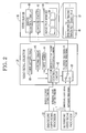
Fig. 2 is a block diagram of a video signal selector and a video server according to a first embodiment; and -
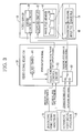
Fig. 3 is a block diagram of a video signal selector and a video server according to a second embodiment. - As shown in
Fig. 1 , a medicalimage filing system 2 for endoscopic ultrasonography (EUS) is constituted of anultrasonic endoscope 10 for taking a video inside a human body cavity, an endoscopicvideo signal processor 12 for producing an endoscopic video signal, an ultrasonicvideo signal processor 14 for producing an ultrasonic video signal, anvideo server 16, and avideo signal selector 18. Thevideo signal selector 18 selects one of the endoscopic video signal and ultrasonic video signal, and outputs the selected signal to thevideo server 16. Thevideo server 16 captures an endoscopic or ultrasonic image from the inputted video signal, and saves the image therein. - The
ultrasonic endoscope 10 has aninsert section 20 to be inserted into the human body cavity, and ahandling section 22 coupled to a proximal end of theinsert section 20. To thehandling section 22, a universal cord is connected. An end of the universal cord is provided with a multi-connector that is connected to both of the endoscopicvideo signal processor 12 and ultrasonicvideo signal processor 14. Thus, theultrasonic endoscope 10 is detachably connected to the endoscopicvideo signal processor 12 and ultrasonicvideo signal processor 14 via the multi-connector. To theultrasonic endoscope 10, a light source unit is also connected for supplying light to the inside of the body cavity. - The
flexible insert section 20 has a tubular shape, round in cross section. Theinsert section 20 has a CCD for optical photography and an ultrasonic transducer array for the EUS at its distal end. A balloon that is inflatable with water, air or the like is also attached to the distal end of theinsert section 20. The balloon is used in the case of, for example, impounding water in the body cavity to prevent attenuation of ultrasonic waves. - On the
handling section 22, an endoscopicimage release button 24 or first operating member is provided for issue of an endoscopic image capture command to thevideo server 16. The endoscopicimage release button 24 is electrically connected to the endoscopicvideo signal processor 12 through the universal cord and the like. - The endoscopic
video signal processor 12 sends a drive signal to theultrasonic endoscope 10, and actuates the CCD in theultrasonic endoscope 10. The endoscopicvideo signal processor 12 receives an analog pickup signal from the CCD, and produces an endoscopic video signal by applying A/D conversion and various video processing to the pickup signal. The endoscopic video signal is outputted to thevideo signal selector 18. - An endoscopic video monitor 26 is connected to the endoscopic
video signal processor 12. The endoscopicvideo signal processor 12 converts the endoscopic video signal into a component or composite video signal compliant with theendoscopic video monitor 26, and outputs the video signal to theendoscopic video monitor 26. Accordingly, the endoscopic video monitor 26 displays a live endoscopic video image on its screen. - In response to a press of the endoscopic
image release button 24, the endoscopicvideo signal processor 12 issues the endoscopic image capture command to thevideo signal selector 18. - The ultrasonic
video signal processor 14 feeds theultrasonic endoscope 10 with exciting pulses (pulse voltage) for making the ultrasonic transducer array produce ultrasonic waves. The ultrasonic transducer array applies the ultrasonic waves to an inner wall of an organ inside the body cavity, and receives reflected waves therefrom. The reflected waves are converted into an electric detection signal by piezoelectric elements in the ultrasonic transducer array, and the detection signal is outputted to the ultrasonicvideo signal processor 14. The ultrasonicvideo signal processor 14 applies A/D conversion and various video processing to the detection signal, and produces an ultrasonic video signal. The ultrasonic video signal is outputted to thevideo signal selector 18. - An ultrasonic video monitor 28 is connected to the ultrasonic
video signal processor 14. The ultrasonicvideo signal processor 14 converts the ultrasonic video signal into a component or composite video signal compliant with theultrasonic video monitor 28, and outputs the video signal to theultrasonic video monitor 28. Accordingly, the ultrasonic video monitor 28 displays a live ultrasonic video image on its screen. - To the ultrasonic
video signal processor 14, akeyboard 30 is connected for entry of various operation commands into the ultrasonicvideo signal processor 14. Thekeyboard 30 is provided with an ultrasonicimage release button 32 or second operating member for issue of an ultrasonic image capture command to thevideo server 16. In response to a press of the ultrasonicimage release button 32, the ultrasonicvideo signal processor 14 outputs the ultrasonic image capture command to thevideo signal selector 18. - As shown in
Fig. 2 , thevideo server 16 is provided with aserver control circuit 40, acapture circuit 42, and animage file memory 44. Theserver control circuit 40 controls theentire video server 16. Thecapture circuit 42 receives the endoscopic or ultrasonic video signal from thevideo signal selector 18. Thecapture circuit 42 extracts data of a single endoscopic still image from the endoscopic video signal, and generates anendoscopic image file 46 in response to a command from theserver control circuit 40. Or, thecapture circuit 42 extracts data of a single ultrasonic still image from the ultrasonic video signal, and generates anultrasonic image file 48. - Upon starting an examination, a
folder 50 is created in theimage file memory 44. Theimage file memory 44 has a plurality offolders 50 that are created on an examination basis. Thecapture circuit 42 generates the endoscopic and ultrasonic image files 46 and 48, and sequentially writes thefiles folder 50. Accordingly, a number of endoscopic and ultrasonic image files 46 and 48 taken in the single examination are stored in thefolder 50 of theimage file memory 44 in proper time sequence. - The
video signal selector 18 is provided with aselector switch 60 or signal switching device, aselector control circuit 62 for controlling theselector switch 60, afirst timer 64, asecond timer 66, and atimer setting dial 68 for setting thesecond timer 66. - The endoscopic video signal and ultrasonic video signal are inputted into the
selector switch 60 from the endoscopicvideo signal processor 12 and ultrasonicvideo signal processor 14, respectively. Theselector switch 60 selects one of the endoscopic video signal and ultrasonic video signal in response to a command from theselector control circuit 62, and outputs the selected signal to thecapture circuit 42. As theselector switch 60, a well-known switching device such as relay and multiplexer is available. - To the
selector control circuit 62, the endoscopic image capture command and ultrasonic image capture command are inputted. Theselector control circuit 62 controls theselector switch 60 in response to the input of each capture command. - The
selector control circuit 62 is connected to theserver control circuit 40 of thevideo server 16. Upon receiving the endoscopic or ultrasonic image capture command, theselector control circuit 62 transfers the inputted capture command to theserver control circuit 40, besides control of theselector switch 60. Theserver control circuit 40 commands thecapture circuit 42 to get the endoscopic or ultrasonic image in response to the capture command from theselector control circuit 62. - The
selector control circuit 62 controls theselector switch 60 so as to select the endoscopic video signal by default, and switch to the ultrasonic video signal only when the ultrasonic image capture command is inputted. When the ultrasonicvideo signal processor 14 issues the ultrasonic image capture command by a press of the ultrasonicimage release button 32, theselector switch 60 is switched from the endoscopic video signal to the ultrasonic video signal in response to a selection switch command from theselector control circuit 62. Accordingly, the ultrasonic video signal is outputted to thecapture circuit 42. - After issue of the selection switch command to the
selector switch 60, theselector control circuit 62 actuates thefirst timer 64 to start counting. While thefirst timer 64 is counting a predetermined time, theselector control circuit 62 holds the ultrasonic image capture command. The instant when the count of thefirst timer 64 has reached the predetermined time, theselector control circuit 62 outputs the ultrasonic image capture command to theserver control circuit 40. Theserver control circuit 40 commands thecapture circuit 42 to get the ultrasonic image in response to the ultrasonic image capture command. Thecapture circuit 42 extracts the ultrasonic image data from the ultrasonic video signal outputted from theselector switch 60, and generates theultrasonic image file 48. Then, thecapture circuit 42 writes theultrasonic image file 48 into theappropriate folder 50 in theimage file memory 44. - The
selector control circuit 62, as described above, outputs the ultrasonic image capture command to theserver control circuit 40 with a delay of predetermined time. Generally speaking, an output signal becomes unstable immediately after switching theselector switch 60, and it takes some time to stabilize the signal. Accordingly, if the ultrasonic image capture command is outputted immediately after switching theselector switch 60, thecapture circuit 42 may read the unstable video signal and generate an abnormalultrasonic image file 48. - The
selector control circuit 62 delays the output of the ultrasonic image capture command in order to prevent the generation of the strangeultrasonic image file 48. Thefirst timer 64 is set at, for example, 0.3 seconds, in consideration of time for stabilization of theselector switch 60. Thefirst timer 64 may be set at appropriate time in accordance with the performance of theselector switch 60. - After the output of the ultrasonic image capture command to the
server control circuit 40, theselector control circuit 62 actuates thesecond timer 66. When the count of thesecond timer 66 has reached a predetermined time, theselector control circuit 62 commands the switching of theselector switch 60. Thus, theselector switch 60 is switched from the ultrasonic video signal to the endoscopic video signal. - The
second timer 66 is set at an appropriate time in accordance with time that thecapture circuit 42 normally writes theultrasonic image file 48 into theimage file memory 44. The set time varies depending on the performance of theconnected video server 16. Accordingly, the set time of the second timer 66 (time to keep selecting the ultrasonic video signal) is variable by thetimer setting dial 68. Therefore, since theselector switch 60 is not switched while thecapture circuit 42 writes theultrasonic image file 48 into theimage file memory 44, it is possible to prevent abnormal write of theultrasonic image file 48. - The
timer setting dial 68 is a well-known operating part such as sliding knob or dial. Thetimer setting dial 68 is provided on a surface of a case of thevideo signal selector 18 for easy setting by a doctor. When a different model ofvideo server 16 is connected to thevideo signal selector 18, the doctor operates thetimer setting dial 68 to set thesecond timer 66 in accordance with the performance of thevideo server 16. Thesecond timer 66 is set variably between, for example, 0.1 seconds and 1.0 second by thetimer setting dial 68. - When the endoscopic
image release button 24 is accidentally pressed during write of theultrasonic image file 48, and theselector switch 60 is switched from ultrasonic video signal to the endoscopic video signal, an abnormalultrasonic image file 48 may be written, as with the above. Accordingly, theselector control circuit 62 does not accept the endoscopic image capture command from the ultrasonicvideo signal processor 12 while thesecond timer 66 operates. - As described above, the
selector control circuit 62 makes theselector switch 60 select the endoscopic video signal by default. When the endoscopic image capture command is inputted from the endoscopicvideo signal processor 12 in response to a press of the endoscopicimage release button 24, theselector control circuit 62 immediately transfers the endoscopic image capture command to theserver control circuit 40, without switching of theselector switch 60 and actuation of thefirst timer 64. - Upon inputting the endoscopic image capture command, the
server control circuit 40 commands thecapture circuit 42 to carry out image capture operation. Thecapture circuit 42 generates theendoscopic image file 46 from the endoscopic video signal outputted from theselector switch 60. Then, thecapture circuit 42 writes theendoscopic image file 46 into theappropriate folder 50 of theimage file memory 44. - Next, the case of observing a lesion in the esophagus will be described. First, the doctor sets up every part as shown in
Fig. 1 , and turns the power on. When the every part has actuated, live video is displayed on the endoscopic and ultrasonic video monitors 26 and 28 (video outside the body cavity at this time, because theinsert section 22 has not been inserted yet). Theselector control circuit 62 commands theselector switch 60 or signal switching device to select the endoscopic video signal, so that the endoscopic video signal is outputted to thecapture circuit 42. - When the endoscopic and ultrasonic video is displayed, the doctor checks the operation of individual parts. At this time, the doctor operates the
timer setting dial 68 as necessary, in order to appropriately set thesecond timer 66 in accordance with thevideo server 16. Then, the doctor presses an examination start button, which is provided on the endoscopicvideo signal processor 12, to start an examination. Upon starting the examination, thefolder 50 for storing images is newly created in theimage file memory 44. - Then, the doctor introduces the
insert section 20 of theultrasonic endoscope 10 into the patient's body cavity while looking at the live endoscopic video on theendoscopic video monitor 26, and starts observing inside the body cavity. If the doctor has found out a lesion in the esophagus in the endoscopic video, the balloon provided at the distal end of theinsert section 20 is inflated by a syringe pump or the like in order to block the esophagus at a point slightly beyond the lesion. - After that, the doctor adjusts the position of the
ultrasonic endoscope 10 so that the lesion is displayed on theendoscopic video monitor 26, and presses the endoscopic image release button (freeze button) 24. Upon pressing the endoscopicimage release button 24, the endoscopicvideo signal processor 12 issues the endoscopic image capture command. The endoscopic image capture command is transmitted to theserver control circuit 40 through theselector control circuit 62. In response to the endoscopic image capture command, theserver control circuit 40 commands thecapture circuit 42 to capture the endoscopic image from the endoscopic video signal outputted from theselector switch 60. Thecapture circuit 42 generates theendoscopic image file 46 having a single frame of a still image from the endoscopic video signal. Accordingly, theendoscopic image file 46 that depicts the surface of the lesion in the esophagus is saved in thefolder 50. - After obtaining the
endoscopic image file 46 of the lesion, water is discharged from the distal end of theinsert section 20 to fill the esophagus, which is blocked by the balloon, with the water for preventing attenuation of the ultrasonic waves. Then, the doctor observes the ultrasonic video on theultrasonic video monitor 28, and presses the ultrasonic image release button (freeze button) 32 at appropriate timing to obtain a desired ultrasonic image. When the ultrasonicimage release button 32 is pressed, the ultrasonic video may be frozen and the ultrasonic image to be saved may be displayed on the ultrasonic video monitor 28 for doctor's convenience. - In response to the press of the ultrasonic
image release button 32, the ultrasonicvideo signal processor 14 issues and outputs the ultrasonic image capture command to theselector control circuit 62. In response to the ultrasonic image capture command, theselector control circuit 62 switches theselector switch 60 from the endoscopic video signal to the ultrasonic video signal. The automatic switching of theselector switch 60 in response to the press of the ultrasonicimage release button 32, as described above, certainly prevents human error, namely forgetting to operate theselector switch 60. There is no need for manual switching operation, and hence the doctor can concentrate on the examination. - When the ultrasonic image capture command is inputted, the
selector control circuit 62 actuates thefirst timer 64, in addition to commanding the switching of theselector switch 60. Then, theselector control circuit 62 delays the ultrasonic image capture command by the predetermined time by thefirst timer 64, and outputs the ultrasonic image capture command to theserver control circuit 40. In response to the ultrasonic image capture command, theserver control circuit 40 commands thecapture circuit 42 to get the ultrasonic image from the ultrasonic video signal outputted from theselector switch 60. Thecapture circuit 42 generates theultrasonic image file 48, which has a single frame of ultrasonic still image, from the ultrasonic video signal. Accordingly, theultrasonic image file 48 that depicts tissue of the lesion under the inner wall of the esophagus is saved in thefolder 50. Delaying the ultrasonic image capture command, as described above, can prevent thecapture circuit 42 from capturing the image from the unstable ultrasonic video signal that is outputted immediately after the switching of theselector switch 60. - After outputting the ultrasonic image capture command to the
server control circuit 40 with a delay, theselector control circuit 62 actuates thesecond timer 66. Thesecond timer 66 starts counting time set by thetimer setting dial 68. When the count of thesecond timer 66 has reached the set time, theselector control circuit 62 commands theselector switch 60 to switch from the ultrasonic video signal to the endoscopic video signal. - After the
ultrasonic image file 48 is saved, the water in the esophagus is removed by suction. Then, the doctor presses the endoscopicimage release button 24 again to obtain anotherendoscopic image file 46. At this time, theselector control circuit 62 does not accept the endoscopic image capture command that is inputted before the switching of theselector switch 60 to the endoscopic video signal. Therefore, it is possible to prevent the switching of theselector switch 60 while thecapture circuit 42 is writing theultrasonic image file 48 on theimage file memory 44. - After saving the second
endoscopic image file 46, the balloon is deflated. Processing for the single lesion has been completed now. The doctor observes inside the body cavity along a route leading to the stomach and duodenum, and repeats the above processing whenever a lesion is found out. When the examination has been completed, theinsert section 20 of theultrasonic endoscope 10 is pulled out of the body cavity. The doctor presses an examination end button provided on the endoscopicvideo signal processor 12 to command the individual parts of theimage filing system 2 to end the examination. - The above
image filing system 2 for theultrasonic endoscope 10 has thesecond timer 66 and thetimer setting dial 68. Thesecond timer 66 is set by thetimer setting dial 68 in accordance with time required by thecapture circuit 42 for normally writing theultrasonic image file 48 on theimage file memory 44. When the count of thesecond timer 66 has reached the set time, theselector switch 60 is switched from the ultrasonic video signal to the endoscopic video signal. - Instead of the above, as shown in
Fig. 3 , a write completion signal that indicates normal completion of write of theultrasonic image file 48 may be inputted from theserver control circuit 40 of thevideo server 16 to theselector control circuit 62 of thevideo signal selector 18. Upon receiving the write completion signal, theselector switch 60 is switched from the ultrasonic video signal to the endoscopic video signal. - In the foregoing embodiments, the
selector switch 60 selects the endoscopic video signal by default, and selects the ultrasonic video signal only when the ultrasonic image capture command is inputted. However, theselector switch 60 or signal switching device may select the endoscopic video signal in response to input of the endoscopic image capture command, and select the ultrasonic video signal in response to input of the ultrasonic image capture command. - Instead of the
ultrasonic endoscope 10, an ultrasonic probe that is inserted into a medical instrument insertion port of an electronic endoscope may be used. - The foregoing embodiments deal with two types of medical video signals, that is, the endoscopic video signal and ultrasonic video signal. However, instead of the ultrasonic video signal, is available a video signal of, for example, an endoscope with an ultrasmall diameter (so-called baby scope) that is inserted into the medical instrument insertion port of the electronic endoscope and used for observation of the biliary tract or the like.
- The
image filing system 2 according to the foregoing embodiments captures the still image from the video signal, and generates the image files 46 and 48. The present invention, however, is applicable to an image filing system that captures moving images and generates a video file. - Although the present invention has been fully described by the way of the preferred embodiment thereof with reference to the accompanying drawings, various changes and modifications will be apparent to those having skill in this field. Therefore, unless otherwise these changes and modifications depart from the scope of the present invention, they should be construed as included therein.
Claims (15)
- A video signal selector (18) comprising:a selector switch (60) for selecting one of a first output mode and a second output mode, for outputting an endoscopic video signal as an output video signal in said first output mode, and outputting another medical video signal as said output video signal in said second output mode, said endoscopic video signal and said medical video signal being inputted in parallel with one another to said selector switch; anda selector control circuit (62) for controlling said selector switch so as to switch from said first output mode to said second output mode in response to a first image capture command for capturing an image (48) from said medical video signal.
- The video signal selector (18) according to claim 1, wherein said selector control circuit (62) further controls said selector switch (60) so as to switch from said second output mode to said first output mode in response to a second image capture command.
- The video signal selector (18) according to claim 2, wherein said first image capture command or said second image capture command is issued in response to operation of a corresponding operating member (24, 32).
- The video signal selector (18) according to claim 3, wherein said video signal selector (60) has an input side and an output side, to said input side an endoscopic video signal processor (12) for producing said endoscopic video signal and a medical video signal processor (14) for producing said medical video signal are connected, to said output side an image server (16) for storing an image (46, 48) is connected, and said image server captures said image from said output video signal selected by said selector switch in response to said first image capture command or said second image capture command.
- The video signal selector (18) according to claim 4, wherein said selector control circuit (62) sends said first image capture command or said second image capture command to said image server (16) with a delay of predetermined time.
- The video signal selector (18) according to claim 4, wherein said selector control circuit (62) controls said selector switch (60) so as to switch from said second output mode to said first output mode, when said image server (16) has completed saving said image (48) captured from said medical video signal.
- The video signal selector (18) according to claim 4, wherein an electronic endoscope (10) is connected to said endoscopic video signal processor (12), an ultrasonic transducer array for taking an ultrasonic video signal as said medical video signal is connected to said medical video signal processor (14), and said ultrasonic transducer array is fixedly or detachably attached to said electronic endoscope.
- The video signal selector (18) according to claim 3, wherein said selector control circuit (62) controls said selector switch (60) so as to select said first output mode by default.
- The video signal selector (18) according to claim 8, wherein said selector control circuit (62) controls said selector switch (60) so as to switch over to said first output mode, when predetermined time has elapsed since said selector switch selected said second output mode.
- The video signal selector (18) according to claim 9, wherein said predetermined time is variable.
- The video signal selector (18) according to claim 4, wherein said selector control circuit (62) refuses acceptance of said second image capture command, while said selector switch (60) is in said second output mode.
- A medical image filing system (2) comprising:an endoscopic video signal processor (12) for producing an endoscopic video signal;a medical video signal processor (14) for producing another medical video signal;a video signal selector (18) to which said endoscopic video signal processor and said medical video signal processor are connected, comprising;(A) a selector switch (60) for selecting one of a first output mode and a second output mode, for outputting said endoscopic video signal as an output video signal in said first output mode, and outputting said medical video signal as said output video signal in said second output mode, said endoscopic video signal and said medical video signal being inputted in parallel with one another to said selector switch; and(B) a selector control circuit (62) for controlling said selector switch so as to switch from said first output mode to said second output mode in response to a first image capture command, and switch from said second output mode to said first output mode in response to a second image capture command; andan image server (16) for capturing an image (46, 48) from said output video signal and saving said image therein in response to said first image capture command or said second image capture command.
- The medical image filing system (2) according to claim 12, wherein said first image capture command or said second image capture command is issued in response to operation of a corresponding operating member (24, 32).
- The medical image filing system (2) according to claim 13, wherein an electronic endoscope (10) is connected to said endoscopic video signal processor (12), an ultrasonic transducer array for taking an ultrasonic video signal as said medical video signal is connected to said medical video signal processor (14), and said ultrasonic transducer array is fixedly or detachably attached to said electronic endoscope.
- The medical image filing system (2) according to claim 14, wherein said image (46, 48) is a still image or moving image.
Applications Claiming Priority (1)
| Application Number | Priority Date | Filing Date | Title |
|---|---|---|---|
| JP2008255787A JP5230331B2 (en) | 2008-09-30 | 2008-09-30 | Video signal switching device |
Publications (1)
| Publication Number | Publication Date |
|---|---|
| EP2168496A1 true EP2168496A1 (en) | 2010-03-31 |
Family
ID=41227270
Family Applications (1)
| Application Number | Title | Priority Date | Filing Date |
|---|---|---|---|
| EP09012033A Withdrawn EP2168496A1 (en) | 2008-09-30 | 2009-09-22 | Video signal selector and medical image filing system therewith |
Country Status (3)
| Country | Link |
|---|---|
| US (1) | US8253785B2 (en) |
| EP (1) | EP2168496A1 (en) |
| JP (1) | JP5230331B2 (en) |
Cited By (1)
| Publication number | Priority date | Publication date | Assignee | Title |
|---|---|---|---|---|
| US12167829B2 (en) | 2019-12-19 | 2024-12-17 | Ambu A/S | Image capture selection |
Families Citing this family (4)
| Publication number | Priority date | Publication date | Assignee | Title |
|---|---|---|---|---|
| KR101070663B1 (en) | 2008-09-30 | 2011-10-07 | 주식회사 바이오넷 | Ultrasonic Diagnosis and Laparoscopy Aparratus for Surgery |
| JP6431815B2 (en) * | 2015-06-18 | 2018-11-28 | オリンパス株式会社 | Endoscope apparatus and endoscope system |
| JP7001556B2 (en) * | 2018-06-29 | 2022-01-19 | 富士フイルム株式会社 | How to operate the ultrasonic diagnostic device and the ultrasonic diagnostic device |
| KR102868454B1 (en) * | 2025-03-07 | 2025-10-02 | 안가연 | Method for Removing Migrating Grass Awns in Companion Animals Using Ultrasound Guidance |
Citations (5)
| Publication number | Priority date | Publication date | Assignee | Title |
|---|---|---|---|---|
| JPH10211201A (en) | 1997-01-31 | 1998-08-11 | Toshiba Corp | Ultrasound diagnostic system |
| JP2004358233A (en) * | 2004-04-26 | 2004-12-24 | Olympus Corp | Image processing apparatus |
| EP1690497A1 (en) * | 2003-12-02 | 2006-08-16 | Olympus Corporation | Ultrasonographic device |
| EP1728463A1 (en) * | 2005-06-02 | 2006-12-06 | Fuji Photo Film Co., Ltd. | Endoscope systems |
| EP1967129A1 (en) * | 2007-03-08 | 2008-09-10 | Olympus Medical Systems Corp. | Medical apparatus obtaining information indicative of internal state of an object based on interaction between sound waves and light |
Family Cites Families (11)
| Publication number | Priority date | Publication date | Assignee | Title |
|---|---|---|---|---|
| JP2556508B2 (en) * | 1987-04-22 | 1996-11-20 | オリンパス光学工業株式会社 | Endoscope device |
| JP2594627B2 (en) * | 1988-02-26 | 1997-03-26 | オリンパス光学工業株式会社 | Electronic endoscope device |
| JPH04894A (en) * | 1990-04-17 | 1992-01-06 | Olympus Optical Co Ltd | Image filing device |
| JPH06169888A (en) * | 1992-12-04 | 1994-06-21 | Toshiba Corp | Electronic endoscopic device |
| JPH07171115A (en) * | 1993-12-17 | 1995-07-11 | Toshiba Corp | Image diagnostic equipment |
| JP2872030B2 (en) * | 1993-12-29 | 1999-03-17 | オリンパス光学工業株式会社 | Ultrasound diagnostic equipment |
| JP3281182B2 (en) * | 1994-06-30 | 2002-05-13 | 株式会社東芝 | Ultrasonic and endoscope combined system |
| JPH10118032A (en) * | 1996-10-24 | 1998-05-12 | Olympus Optical Co Ltd | Image displaying apparatus for medical treatment and method therefor |
| JP2007275309A (en) * | 2006-04-06 | 2007-10-25 | Olympus Medical Systems Corp | Medical system |
| JP4800127B2 (en) * | 2006-06-29 | 2011-10-26 | 富士フイルム株式会社 | Medical image segmentation device and medical image segmentation program |
| JP5052123B2 (en) * | 2006-12-27 | 2012-10-17 | 富士フイルム株式会社 | Medical imaging system and method |
-
2008
- 2008-09-30 JP JP2008255787A patent/JP5230331B2/en active Active
-
2009
- 2009-09-22 EP EP09012033A patent/EP2168496A1/en not_active Withdrawn
- 2009-09-22 US US12/564,760 patent/US8253785B2/en active Active
Patent Citations (5)
| Publication number | Priority date | Publication date | Assignee | Title |
|---|---|---|---|---|
| JPH10211201A (en) | 1997-01-31 | 1998-08-11 | Toshiba Corp | Ultrasound diagnostic system |
| EP1690497A1 (en) * | 2003-12-02 | 2006-08-16 | Olympus Corporation | Ultrasonographic device |
| JP2004358233A (en) * | 2004-04-26 | 2004-12-24 | Olympus Corp | Image processing apparatus |
| EP1728463A1 (en) * | 2005-06-02 | 2006-12-06 | Fuji Photo Film Co., Ltd. | Endoscope systems |
| EP1967129A1 (en) * | 2007-03-08 | 2008-09-10 | Olympus Medical Systems Corp. | Medical apparatus obtaining information indicative of internal state of an object based on interaction between sound waves and light |
Cited By (1)
| Publication number | Priority date | Publication date | Assignee | Title |
|---|---|---|---|---|
| US12167829B2 (en) | 2019-12-19 | 2024-12-17 | Ambu A/S | Image capture selection |
Also Published As
| Publication number | Publication date |
|---|---|
| US20100079586A1 (en) | 2010-04-01 |
| JP5230331B2 (en) | 2013-07-10 |
| JP2010082283A (en) | 2010-04-15 |
| US8253785B2 (en) | 2012-08-28 |
Similar Documents
| Publication | Publication Date | Title |
|---|---|---|
| US11998396B2 (en) | Ultrasound diagnostic apparatus and operation method of ultrasound diagnostic apparatus | |
| JP5198118B2 (en) | Adapter device and ultrasonic inspection system | |
| CN100496379C (en) | Endoscope and display device | |
| US8253785B2 (en) | Video signal selector and medical image filing system therewith | |
| US12369889B2 (en) | Ultrasound diagnostic apparatus and operation method of ultrasound diagnostic apparatus | |
| JP2009254773A (en) | Ultrasonic diagnosis system and pump apparatus | |
| EP2704439A1 (en) | Medical image recording apparatus, recording method of the same, and medical image recording program | |
| US11607201B2 (en) | Ultrasound diagnostic apparatus and operation method of ultrasound diagnostic apparatus by determining depolarization to necessitate supply of polarization voltage to ultrasound transducers | |
| JP2009233247A (en) | Ultrasonic examination system and image processing apparatus | |
| US6869400B2 (en) | Medical unit | |
| JPWO2010050555A1 (en) | Ultrasonic observation equipment | |
| WO2021039101A1 (en) | Ultrasonic endoscope system and operating method for ultrasonic endoscope system | |
| JP2020156730A (en) | Ultrasonic observation device and ultrasonic endoscopy system | |
| CN111685794B (en) | Ultrasonic diagnostic system and method for operating ultrasonic diagnostic system | |
| JP2009213630A (en) | Endoscope system and processor | |
| JP2005334275A (en) | Endoscope | |
| JP6912925B2 (en) | Image recording / playback device and endoscopic system | |
| JP2010011894A (en) | Endoscope system and switching unit | |
| JP5127596B2 (en) | Processor device for electronic endoscope | |
| JP4731250B2 (en) | Electronic endoscope device | |
| JP2010011893A (en) | Endoscope system and switching unit | |
| JP2017006261A (en) | Endoscope apparatus and endoscope system | |
| JP2007244464A (en) | Electronic endoscope processor and electronic endoscope system | |
| JP2007054097A (en) | Medical image processor device | |
| JP2010088673A (en) | Processor apparatus for endoscope, and method for verifying operation of circuit board of the processor apparatus for endoscope |
Legal Events
| Date | Code | Title | Description |
|---|---|---|---|
| PUAI | Public reference made under article 153(3) epc to a published international application that has entered the european phase |
Free format text: ORIGINAL CODE: 0009012 |
|
| AK | Designated contracting states |
Kind code of ref document: A1 Designated state(s): AT BE BG CH CY CZ DE DK EE ES FI FR GB GR HR HU IE IS IT LI LT LU LV MC MK MT NL NO PL PT RO SE SI SK SM TR |
|
| AX | Request for extension of the european patent |
Extension state: AL BA RS |
|
| 17P | Request for examination filed |
Effective date: 20100915 |
|
| 17Q | First examination report despatched |
Effective date: 20110103 |
|
| STAA | Information on the status of an ep patent application or granted ep patent |
Free format text: STATUS: THE APPLICATION IS DEEMED TO BE WITHDRAWN |
|
| 18D | Application deemed to be withdrawn |
Effective date: 20160401 |