EP2168019B1 - Datenerfassungssystem mit selbstkonfiguration für diagnostische tests - Google Patents
Datenerfassungssystem mit selbstkonfiguration für diagnostische tests Download PDFInfo
- Publication number
- EP2168019B1 EP2168019B1 EP08780739A EP08780739A EP2168019B1 EP 2168019 B1 EP2168019 B1 EP 2168019B1 EP 08780739 A EP08780739 A EP 08780739A EP 08780739 A EP08780739 A EP 08780739A EP 2168019 B1 EP2168019 B1 EP 2168019B1
- Authority
- EP
- European Patent Office
- Prior art keywords
- data acquisition
- unit
- sensor
- equipment device
- diagnostic testing
- Prior art date
- Legal status (The legal status is an assumption and is not a legal conclusion. Google has not performed a legal analysis and makes no representation as to the accuracy of the status listed.)
- Active
Links
Images


Classifications
-
- G—PHYSICS
- G05—CONTROLLING; REGULATING
- G05B—CONTROL OR REGULATING SYSTEMS IN GENERAL; FUNCTIONAL ELEMENTS OF SUCH SYSTEMS; MONITORING OR TESTING ARRANGEMENTS FOR SUCH SYSTEMS OR ELEMENTS
- G05B23/00—Testing or monitoring of control systems or parts thereof
- G05B23/02—Electric testing or monitoring
- G05B23/0205—Electric testing or monitoring by means of a monitoring system capable of detecting and responding to faults
- G05B23/0208—Electric testing or monitoring by means of a monitoring system capable of detecting and responding to faults characterized by the configuration of the monitoring system
- G05B23/0213—Modular or universal configuration of the monitoring system, e.g. monitoring system having modules that may be combined to build monitoring program; monitoring system that can be applied to legacy systems; adaptable monitoring system; using different communication protocols
Definitions
- the present invention is related generally to data acquisition systems for diagnostic system and, more particularly, to self-configuring data acquisition systems for diagnostic systems.
- Portable data acquisition systems are used in the nuclear power industry to measure the performance characteristics of power-operated valves and motors.
- Various commercially available sensors such as motor current probes and pressure transmitters, and valve-specific sensors, such as strain gage instruments and displacement measuring tools, are used simultaneously on a valve to determine the condition of the valve and its performance.
- various sensors and signal conditioning channels will be used.
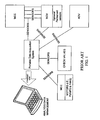
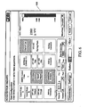
- FIG. 1 illustrates the VIPER 20 portable data acquisition system.
- the user must plug the sensor into the correct card and then manually input the sensor type, serial number, sensitivity (i.e., conversion factor to translate a signal to proper engineering units), calibration due date, units of measure (i.e., pounds, amperes, inches, etc.) into the transducer database of the software. In the software, the user then must associate the channel used with the sensor in the transducer database.
- sensor type serial number
- sensitivity i.e., conversion factor to translate a signal to proper engineering units
- calibration due date i.e., units of measure (i.e., pounds, amperes, inches, etc.) into the transducer database of the software.
- units of measure i.e., pounds, amperes, inches, etc.
- the user must also select the equipment to be monitored from the valve database in the software. If the equipment is not listed in the valve database, the user must create the entry and input pertinent information about it. The user then connects the sensors to the valve and operates the valve. As the valve operates, data from all sensors is acquired. Once data acquisition is complete, the analog signals are converted to digital signals and sent to a notebook computer over an Ethernet link. In the software, the raw data is stored along with a conversion factor. The user can then analyze the data, print graphs, mark events, print reports, etc.
- Exemplary embodiments of the self-configuring data acquisition system include sensors, signal conditioning modules, data transmission means, a central system and data recording means and is used to periodically test process equipment to verify correct configuration and operability and to facilitate necessary adjustments.
- Automatic identification of the equipment under test, sensors, and signal conditioning modules is provided by digital information units that are installed in, or affixed to, equipment devices, sensors, and signal conditioning units, and transmit the associated identifying information to a data acquisition processing unit.
- a self-configuring data acquisition system for conducting diagnostic testing of process equipment devices.
- the data acquisition system includes a data acquisition processing unit for controlling diagnostic testing of an equipment device, the equipment device including a digital information unit that stores information uniquely identifying the equipment device and automatically transmits the identifying information to the data acquisition unit.
- a signal conditioning unit is coupled to the data acquisition unit by a first data transmission means, the signal conditioning unit including a digital information unit that stores information uniquely identifying the signal conditioning unit and automatically transmits the identifying information to the data acquisition unit.
- a sensor is associated with the equipment device under test, wherein the sensor is coupled to the signal conditioning unit by a second data transmission means, the sensor including a digital information unit that stores information uniquely identifying the sensor and automatically transmits the identifying information to the data acquisition unit.
- a component receives the identifying information from the sensor and equipment device digital information units and automatically configures the signal conditioning unit, based on the sensor and equipment device identifying information, to excite the equipment device under test and receive a plurality of test data input signals from the equipment device resulting from the excitation.
- a method for automatically conducting diagnostic testing of process equipment devices in a data acquisition system.
- the method includes the steps of: providing a digital information unit for each of a plurality of components of the data acquisition system including an equipment device under test, a signal conditioning unit, and a sensor associated with an equipment device under test, each digital information unit including information that uniquely identifies a corresponding component; automatically transmitting the identifying information stored on each digital information unit to a data acquisition processing unit; automatically configuring the signal conditioning unit, based on the sensor and equipment device identifying information, to excite the equipment device under test; and receiving a plurality of test data input signals from the equipment device resulting from the excitation by the signal conditioning unit.
- Fig. 1 illustrates a prior art portable data acquisition system used in the nuclear power industry.
- Fig. 2 illustrates a system architecture of the self-configuring data acquisition system in accordance with an embodiment of the invention.
- Fig. 3 illustrates a data processing architecture of the self-configuring data acquisition system in accordance with an embodiment of the invention.
- Figs. 4-6 illustrate a series of user interfaces for the data acquisition wizard in accordance with an embodiment of the invention.
- Fig. 7 illustrates an exemplary circuit diagram for a digital information identification unit.
- the self-configuring data acquisition system includes sensors, signal conditioning modules, data transmission means, a central system and data recording means and is used to periodically test process equipment to verify correct configuration and operability and to facilitate necessary adjustments.
- Embodiments of the portable diagnostic system for use in the nuclear power industry can acquire and analyze data on air-operated valves (AOV), motor-operated valves (MOV), and check valves.
- the portable diagnostic system is designed as a rugged, portable acquisition system that provides a step-change improvement in technology when compared to prior art systems.
- embodiments of the portable diagnostic system provide a reduction in complexity making the system easier to transport, use and maintain and allowing increased accuracy.
- Fig. 2 illustrates an exemplary system architecture.
- the exemplary portable diagnostic system 100 includes the following assemblies: sensors 10, sensor cables 20, data acquisition unit (DAU) 30, contacts cable assembly (CCA) 40, eddy current signal conditioning assembly (ECSCA) 50, AC power supplies 60 for the DAU 30 and ECSCA 50, and a portable computer (PC) 70.
- the system can support 12 universal connectors. Additional features include a built-in wireless capability, an eight-hour capacity battery for the DAU 30, automatic identification of sensors and valves, interchangeable cables, a voice communication option and the ability to run the software on an ultra-mobile PC 70.
- the communications interfaces of the portable diagnostic system 100 comply with both the Ethernet 100BaseT wired and IEEE 801.11g wireless standards by using commercially available modular technology.
- the contacts cable assembly 40 internal circuitry detects impedance change across a switch. If the detected current is above a threshold value, the switch is considered closed. Otherwise, the switch is considered open.
- the CCA assembly 40 can monitor six switches: three open and three closed (i.e., torque, bypass, limit).
- the CCA assembly 40 multiplexes individual digital detections into an analog signal.
- the CCA assembly 40 output analog signal varies based on an open or closed condition of each input switch.
- the eddy current signal conditioning assembly 50 includes two eddy current sensors that are used to measure the position of a disk in a check valve with electromagnetic principles.
- the ECSCA 50 excites the sensors and performs signal conditioning of the amplified return for a two-valve configuration into the DAU 30.
- the power supplies 60 provide an alternating current voltage operating range from 85 VAC to 260 VAC at 50/60 Hz.
- the power supplies 60 utilize automatic switching for varying voltage inputs.
- the same power supply can be used for both DAU 30 and ECSCA 50.
- the PC 70 that communicates with DAU 30 should have the following minimum characteristics: minimum of 512 megabytes of RAM, minimum of 30 gigabytes of hard disk storage, an internal battery, Ethernet 100baseT and IEEE 802.11 g wireless capability, minimum screen resolution of 800 x 400 pixels, USB 2.0 compliant expansion and microphone, headset, mouse, and keyboard interfaces.
- Ethernet 100BaseT capability is provided by an installed Ethernet adapter and an RJ-45 connector.
- the IEEE 802.11g wireless capability is provided by an installed wireless adapter.
- the DAU 30 processor should have the capabilities identified herein.
- the DAU 30 processor (32 bit) should be able to initialize all hardware, save configuration and identification information, and communicate between the sensors 10 and the PC 70.
- the DAU 30 processor should have the ability to distinguish between a wired or wireless Ethernet connection.
- the DAU 30 processor should be capable of loading a complete operating system (OS) image and incorporating a real time clock for data synchronization with multiple DAUs.
- the DAU 30 processor should also include a built-in low-powered, high efficiency switcher supply.
- the DAU 30 software should be upgradeable remotely over the network.
- the DAU 30 processor should use multiple clock modes for various operation conditions with clock rates that are adjustable based on current processor requirements.
- the DAU 30 processor should have adequate flash memory for boot loader, OS and application program storage.
- the DAU 30 processor should have adequate random access memory (RAM) for the application program and at least 64 Mbytes for data retention.
- the DAU 30 processor should be capable of saving all configuration data during power interruption.
- Voice over IP (VoIP) functionality could be accessible to the analysis PC 70 through hardware and software.
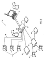
- Fig. 3 illustrates a data processing architecture 300 of the self-configuring data acquisition system in an embodiment of the invention.
- a digital information unit (DIU) 320 in each element of the data acquisition system 300 provides individual identification of the element and other configuring information to a central recording function of the system.
- These digital information units 320 are installed in each sensor 314, 316, 318, signal conditioning module 304, data transmission component 312 (wireless), 322 (wired), and peripheral device 302, 306, 308 of the system.
- Each component of process equipment 330, 340 to be tested is also equipped with a digital information unit 320. Potentially, each person 310 operating the data acquisition system 300 could use a digital information unit 320 to identify themselves as the operator of a given test or sequence.
- the operator 310 would be required to enter little or no information.
- the system 300 would be connected and would self-configure, and the relevant type of test that would be triggered and stored with no required user interaction. Some selection options might be desired, but these could be reduced to the simplest possible interface (a two-state button or other binary device).
- Digital information units 320 are nonvolatile and cannot be altered in normal operation of the data acquisition system 300.
- the digital information units 320 are writable with a provided device.
- Each unit 320 is initially written with permanent information pertaining to the element it will describe, such as the identification number or name of the element, serial numbers, size, capacity, etc.
- the unit 320 can also contain current information pertaining to the element such as date last tested, date last calibrated, test or calibration values, current settings, or set point limits. Writing devices adapted to each circumstance (a sensor or module being periodically calibrated, a piece of equipment being tested, set point values being changed, etc.) are available.
- the data acquisition system 300 When initiating a test, the data acquisition system 300 will query all connected elements and will self-configure based on the information returned from the digital information units 320. This eliminates the need for the operator 310 to enter information for system components, sensors, equipment being tested, etc., both automating the setup and eliminating transcription and other input errors.
- Data transmission means 312, 322 interconnect system subcomponents such as sensors 314, 316, 318, and signal conditioning module 304, which may be either wired or wireless, and are generic in design. Electrical connections are generic and interchangeable wherever possible.
- the automated configuration function will include the configuration of data transmission means 312, 322, signal conditioning modules 304, system circuits, and other elements to provide the needed electrical connections, sensing circuits, power or excitation circuits, etc. to any connected element based on its identity as conveyed by the digital information unit associated with it.
- Digital information units 320 can be physically installed in some elements, such as sensors that would normally have electrical circuits that connect to the system.
- the units 320 can be attached to equipment as tags or placed in identified locations near the subject elements where they can be scanned or read by a device associated with the system.
- Units 320 may also be carried by operators 310 as means of user identification or system access.
- Embodiments of the present invention utilize digital information ID chip technology to configure the diagnostic system for data acquisition.
- Each sensor 314, 316, 318 used with the diagnostic system 300 should contain this digital information ID chip 320. Every connector on the signal processing unit 304 will be identical and contain the circuitry necessary for all types of sensors.
- the diagnostic system 300 will identify it, configure the appropriate circuitry for the device, and provide an indication that the sensor is connected and providing a good signal. The serial number, calibration information, and sensitivity of the device are automatically recorded and stored in the software database for the test.
- the digital information ID chips 320 are writable to store information on the component to be tested.
- Each valve in the plant can then have a tag affixed to it such that when plugged into the diagnostic system 300 will automatically configure the signal processing unit 304 to acquire data for that particular valve and store the data in the appropriate location 306.
- Fig. 7 illustrates an exemplary circuit diagram 700 for a digital information ID unit.
- the digital information identification (ID) chip 320 should have the following characteristics:
- DS2432 that combines 1024 bits of EEPROM with a 64-bit secret and 512-bit secure hash algorithm.
- the DS2432 provides a read memory command that automatically computes and delivers a 160-bit MAC to the 1-wire host (i.e., DAU 30).
- Each DS2432 has its own factory-lasered 64-bit ROM registration number to provide a unique ID for the system in which it is embedded.
- Fig. 4 illustrates an exemplary user interface 400 for the acquisition unit wizard.
- a combination box 410 is provided for the user 310 to select a signal conditioning unit (i.e., data acquisition unit) 304.
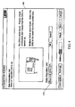
- Fig. 5 illustrates an exemplary user interface 500 for the acquisition unit wizard. If no valve tag ID is connected, the software of data acquisition unit 302 will prompt the user 310 to select a valve from the database in drop down box 510.
- the diagnostic system 300 will read the digital information ID tags 320 of all the sensors/devices plugged into the SCU 304. Based on the sensor IDs, the diagnostic system 300 will automatically configure the SCU 304 hardware 40, 50, 54, 58 to provide the necessary excitation to the device and receive the input signal. The diagnostic system 300 will also store the appropriate sensor information in the record for the test.
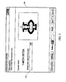
- the exemplary screen 600 of Fig. 6 will auto-populate information into the PC 302 application software for the connected sensors 314, 316, 318 and valves 330, 340 to include type, serial/model number, and calibration information.
Landscapes
- Physics & Mathematics (AREA)
- General Physics & Mathematics (AREA)
- Engineering & Computer Science (AREA)
- Automation & Control Theory (AREA)
- Testing And Monitoring For Control Systems (AREA)
- Arrangements For Transmission Of Measured Signals (AREA)
- Selective Calling Equipment (AREA)
Claims (27)
- Datenerfassungssystem zum Durchführen einer Diagnoseprüfung von Prozessanlagenvorrichtungen, das umfasst:eine Datenerfassungsverarbeitungseinheit (302) zum Steuern der Diagnoseprüfung einer Anlagenvorrichtung,eine Einheit (320) für digitale Informationen, die der Anlagenvorrichtung zugeordnet ist, wobei die Einheit für digitale Informationen Informationen speichert, die die Anlagenvorrichtung eindeutig identifizieren, und die Anlagenvorrichtungs-Identifikationsinformationen automatisch zur Datenerfassungsverarbeitungseinheit überträgt; undeinen Sensor (314, 316, 318), der mit der geprüften Anlagenvorrichtung gekoppelt ist;gekennzeichnet durcheine Signalaufbereitungseinheit (304), die mit der Datenerfassungseinheit durch eine erste Datenübertragungseinrichtung gekoppelt ist, wobei die Signalaufbereitungseinheit eine Einheit für digitale Informationen umfasst, die Informationen speichert, die die Signalaufbereitungseinheit eindeutig identifizieren, und die Signalaufbereitungseinheits-Identifikationsinformationen automatisch zur Datenerfassungsverarbeitungseinheit überträgt, wobei der Sensor ferner mit der Signalaufbereitungseinheit durch eine zweite Datenübertragungseinrichtung gekoppelt ist, und wobei der Sensor eine Einheit für digitale Informationen umfasst, die Informationen speichert, die den Sensor eindeutig identifizieren, und die Sensoridentifikationsinformationen automatisch zur Datenerfassungsverarbeitungseinheit überträgt; undeine Komponente zum automatischen Konfigurieren der Signalaufbereitungseinheit für jede Verwendung des Datenerfassungssystems auf der Basis der Sensor- und Anlagenvorrichtungs-Identifikationsinformationen, die durch die Datenerfassungsverarbeitungseinheit empfangen werden, um den mit der geprüften Anlagenvorrichtung gekoppelten Sensor anzuregen und eine Vielzahl von Testdateneingangssignalen, die sich aus der Anregung ergeben, zu empfangen, so dassdas Datenerfassungssystem selbstkonfigurierend ist, wobei das Datenerfassungssystem tragbar ist.
- Selbstkonfigurierendes Datenerfassungssystem zum Durchführen einer Diagnoseprüfung nach Anspruch 1, das ferner eine Datenspeichervorrichtung, die mit der Datenerfassungseinheit gekoppelt ist, zum Speichern der Vielzahl von Testdateneingangssignalen umfasst.
- Selbstkonfigurierendes Datenerfassungssystem zum Durchführen einer Diagnoseprüfung nach Anspruch 1, wobei die Einheit für digitale Informationen des Sensors eine Seriennummer und Kalibrierungsinformationen und/oder eine Empfindlichkeit des Sensors speichert.
- Selbstkonfigurierendes Datenerfassungssystem zum Durchführen einer Diagnoseprüfung nach Anspruch 3, wobei die in der Einheit für digitale Informationen des Sensors gespeicherten Informationen in der Datenspeichervorrichtung automatisch aufgezeichnet und gespeichert werden.
- Selbstkonfigurierendes Datenerfassungssystem zum Durchführen einer Diagnoseprüfung nach Anspruch 1, wobei die Einheit für digitale Informationen des Sensors eine automatische Eindraht-Identifikationsvorrichtung umfasst.
- Selbstkonfigurierendes Datenerfassungssystem zum Durchführen einer Diagnoseprüfung nach Anspruch 1, wobei die Einheit für digitale Informationen des Sensors im Sensor installiert ist oder wobei die Einheit für digitale Informationen des Sensors als Anhänger am Sensor befestigt ist.
- Selbstkonfigurierendes Datenerfassungssystem zum Durchführen einer Diagnoseprüfung nach Anspruch 1, wobei die Einheit für digitale Informationen, die der geprüften Anlagenvorrichtung zugeordnet ist, durch einen Abtaster gelesen werden kann und in der Nähe der geprüften Anlagenvorrichtung angeordnet ist.
- Selbstkonfigurierendes Datenerfassungssystem zum Durchführen einer Diagnoseprüfung nach Anspruch 7, wobei die Einheit für digitale Informationen, die der geprüften Anlagenvorrichtung zugeordnet ist, mindestens eine der folgenden Daten für die Anlagenvorrichtung speichert: ein Datum der letzten Prüfung, ein Datum der letzten Kalibrierung, einen Prüfwert, einen Kalibrierungswert, eine aktuelle Einstellung und eine Sollwertgrenze.
- Selbstkonfigurierendes Datenerfassungssystem zum Durchführen einer Diagnoseprüfung nach Anspruch 1, wobei die Komponente zum automatischen Konfigurieren der Signalaufbereitungseinheit ein Softwaremodul umfasst, das in der Datenerfassungseinheit installiert ist.
- Selbstkonfigurierendes Datenerfassungssystem zum Durchführen einer Diagnoseprüfung nach Anspruch 1, wobei die erste Datenübertragungseinrichtung entweder einen verdrahteten oder einen drahtlosen Kommunikationsadapter zwischen der Signalaufbereitungseinheit und der Datenerfassungseinheit umfasst.
- Selbstkonfigurierendes Datenerfassungssystem zum Durchführen einer Diagnoseprüfung nach Anspruch 1, wobei die erste Datenübertragungseinrichtungsverbindung einen Ethernet-100BaseT-Adapter umfasst oder wobei die erste Datenübertragungseinrichtung einen drahtlosen Adapter umfasst.
- Selbstkonfigurierendes Datenerfassungssystem zum Durchführen einer Diagnoseprüfung nach Anspruch 1, wobei die zweite Datenübertragungseinrichtung entweder einen verdrahteten oder einen drahtlosen Kommunikationsadapter zwischen der Signalaufbereitungseinheit und dem Sensor umfasst.
- Selbstkonfigurierendes Datenerfassungssystem zum Durchführen einer Diagnoseprüfung nach Anspruch 1, wobei die zweite Datenübertragungseinrichtungsverbindung einen Ethernet-100BaseT-Adapter umfasst oder wobei die zweite Datenübertragungseinrichtung einen drahtlosen Adapter umfasst.
- Selbstkonfigurierendes Datenerfassungssystem zum Durchführen einer Diagnoseprüfung nach Anspruch 1, wobei die geprüfte Anlagenvorrichtung ein motorbetätigtes Ventil, ein luftbetätigtes Ventil und/oder ein Rückschlagventil umfasst.
- Selbstkonfigurierendes Datenerfassungssystem zum Durchführen einer Diagnoseprüfung nach Anspruch 14, wobei die Anlagenvorrichtung in einer Kraftwerkinstallation am Einsatzort geprüft wird.
- Selbstkonfigurierendes Datenerfassungssystem zum Durchführen einer Diagnoseprüfung nach Anspruch 9, das ferner eine Software-Benutzerschnittstelle zum Auswählen einer Datenerfassungseinheit zum Steuern einer Diagnoseprüfung und, falls sie durch das Softwaremodul aufgefordert wird, zum Auswählen der zu prüfenden Anlagenvorrichtung umfasst.
- Verfahren zum automatischen Durchführen einer Diagnoseprüfung von Prozessanlagenvorrichtungen unter Verwendung eines selbstkonfigurierenden tragbaren Datenerfassungssystems, wobei jeder Anlagenvorrichtung eine Einheit für digitale Informationen zugeordnet ist, wobei die Einheit für digitale Informationen Informationen speichert, die die Anlagenvorrichtung eindeutig identifizieren, gekennzeichnet durch:Vorsehen einer Einheit für digitale Informationen für jede einer Vielzahl von Komponenten des Datenerfassungssystems, einschließlich einer Signalaufbereitungseinheit mit einer Vielzahl von universellen Verbindungselementen und eines Sensors, der der geprüften Anlagenvorrichtung zugeordnet ist, wobei jede Einheit für digitale Informationen Informationen speichert, die eine entsprechende Komponente eindeutig identifizieren;automatisches Empfangen der in jeder Einheit für digitale Informationen gespeicherten Identifikationsinformationen durch eine Datenerfassungsverarbeitungseinheit;automatisches Konfigurieren der Signalaufbereitungseinheit auf der Basis der Sensor- und der Anlagenvorrichtungs-Identifikationsinformationen, die durch die Datenerfassungsverarbeitungseinheit empfangen werden, um den der geprüften Anlagenvorrichtung zugeordneten Sensor anzuregen; undEmpfangen einer Vielzahl von Testdateneingangssignalen von dem der Anlagenvorrichtung zugeordneten Sensor, die sich aus der Anregung ergeben, durch die Signalaufbereitungseinheit.
- Verfahren zum automatischen Durchführen einer Diagnoseprüfung nach Anspruch 17, das ferner das Speichern der Vielzahl von Testdatensignalen in einer Datenspeichervorrichtung umfasst.
- Verfahren zum automatischen Durchführen einer Diagnoseprüfung nach Anspruch 17, das ferner das Speichern einer Seriennummer und von Kalibrierungsinformationen und/oder der Empfindlichkeit in der Einheit für digitale Informationen des Sensors umfasst.
- Verfahren zum automatischen Durchführen einer Diagnoseprüfung nach Anspruch 19, das ferner das automatische Aufzeichnen und Speichern der in der Einheit für digitale Informationen des Sensors gespeicherten Informationen in der Datenspeichervorrichtung umfasst.
- Verfahren zum automatischen Durchführen einer Diagnoseprüfung nach Anspruch 17, das ferner das Installieren einer Einheit für digitale Informationen im Sensor umfasst oder ferner das Befestigen einer Einheit für digitale Informationen am Sensor als Anhänger umfasst oder ferner das Befestigen einer Einheit für digitale Informationen an der geprüften Anlagenvorrichtung als Anhänger umfasst.
- Verfahren zum automatischen Durchführen einer Diagnoseprüfung nach Anspruch 17, das ferner das Auffinden einer Einheit für digitale Informationen in der Nähe der geprüften Anlage und das Abtasten der in der Einheit für digitale Informationen gespeicherten Informationen und das Übertragen der abgetasteten Informationen zur Signalaufbereitungseinheit umfasst.
- Verfahren zum automatischen Durchführen einer Diagnoseprüfung nach Anspruch 22, wobei die Einheit für digitale Informationen, die der geprüften Anlagenvorrichtung entspricht, mindestens eine der folgenden Daten für die Anlagenvorrichtung speichert: ein Datum der letzten Prüfung, ein Datum der letzten Kalibrierung, einen Prüfwert, einen Kalibrierungswert, eine aktuelle Einstellung und eine Sollwertgrenze.
- Verfahren zum automatischen Durchführen einer Diagnoseprüfung nach Anspruch 17, das ferner das Vorsehen einer verdrahteten oder einer drahtlosen Verbindung zur Übertragung von Informationen zwischen der Signalaufbereitungseinheit und der Datenerfassungsverarbeitungseinheit, die die Diagnoseprüfung der Anlagenvorrichtung steuert, umfasst.
- Verfahren zum automatischen Durchführen einer Diagnoseprüfung nach Anspruch 17, das ferner das Vorsehen einer verdrahteten oder einer drahtlosen Verbindung zur Übertragung von Informationen zwischen dem Sensor und der Signalaufbereitungseinheit umfasst.
- Verfahren zum automatischen Durchführen einer Diagnoseprüfung nach Anspruch 17, wobei die geprüfte Anlagenvorrichtung ein motorbetätigtes Ventil, ein luftbetätigtes Ventil und/oder ein Rückschlagventil umfasst.
- Datenerfassungssystem nach Anspruch 1, wobei die Datenerfassungsverarbeitungseinheit die Komponente zum automatischen Konfigurieren der Signalaufbereitungseinheit für jede Verwendung des tragbaren Datenerfassungssystems auf der Basis der Sensor- und Anlagenvorrichtungs-Identifikationsinformationen, die durch die Datenerfassungsverarbeitungseinheit von der jeweiligen Einheit für digitale Informationen empfangen werden, automatisch konfiguriert, um den mit der geprüften Anlagenvorrichtung gekoppelten Sensor anzuregen und eine Vielzahl von Datensignalen zu empfangen, die sich aus der Anregung ergeben.
Applications Claiming Priority (3)
| Application Number | Priority Date | Filing Date | Title |
|---|---|---|---|
| US94334207P | 2007-06-12 | 2007-06-12 | |
| US11/764,812 US20080309507A1 (en) | 2007-06-12 | 2007-06-19 | Self-configuring data acquisition system for diagnostic testing |
| PCT/US2008/065468 WO2008154195A1 (en) | 2007-06-12 | 2008-06-02 | Self-configuring data acquisition system for diagnostic testing |
Publications (2)
| Publication Number | Publication Date |
|---|---|
| EP2168019A1 EP2168019A1 (de) | 2010-03-31 |
| EP2168019B1 true EP2168019B1 (de) | 2012-03-07 |
Family
ID=39769303
Family Applications (1)
| Application Number | Title | Priority Date | Filing Date |
|---|---|---|---|
| EP08780739A Active EP2168019B1 (de) | 2007-06-12 | 2008-06-02 | Datenerfassungssystem mit selbstkonfiguration für diagnostische tests |
Country Status (9)
| Country | Link |
|---|---|
| US (1) | US20080309507A1 (de) |
| EP (1) | EP2168019B1 (de) |
| JP (1) | JP5584118B2 (de) |
| KR (1) | KR101485210B1 (de) |
| AT (1) | ATE548683T1 (de) |
| CA (1) | CA2687502C (de) |
| ES (1) | ES2384008T3 (de) |
| TW (1) | TW200951990A (de) |
| WO (1) | WO2008154195A1 (de) |
Families Citing this family (10)
| Publication number | Priority date | Publication date | Assignee | Title |
|---|---|---|---|---|
| AU2007276688A1 (en) * | 2006-07-17 | 2008-01-24 | Signostics Limited | Improved medical diagnostic device |
| WO2011053182A1 (ru) * | 2009-11-02 | 2011-05-05 | Leontiev Vladimir Vasilievich | Устройство накопления и обработки информации (унои) |
| CN102650548A (zh) * | 2012-04-11 | 2012-08-29 | 上海瑞视仪表电子有限公司 | 一种智能点检定修仪 |
| US20140032158A1 (en) * | 2012-07-27 | 2014-01-30 | Altran Solutions Corp. | Automated test system |
| US8775691B1 (en) * | 2012-12-18 | 2014-07-08 | International Business Machines Corporation | Detecting firmware version for an input/output adapter |
| US9171192B2 (en) * | 2013-04-29 | 2015-10-27 | Aktiebolaget Skf | One touch data collection method and medium |
| CN113650572A (zh) * | 2021-08-31 | 2021-11-16 | 上海怿星电子科技有限公司 | 一种驾驶辅助系统的传感器采集设备和方法 |
| CN114659479B (zh) * | 2022-03-04 | 2023-12-05 | 江苏汇智高端工程机械创新中心有限公司 | 一种智能化线位移传感器测试方法 |
| CN115859934A (zh) * | 2022-12-15 | 2023-03-28 | 立讯精密组件(苏州)有限公司 | 一种数据处理方法、装置、电子设备及存储介质 |
| KR102508746B1 (ko) * | 2022-12-15 | 2023-03-14 | 주식회사 신평산업 | 엣지 컨트롤러 시스템 |
Family Cites Families (39)
| Publication number | Priority date | Publication date | Assignee | Title |
|---|---|---|---|---|
| US4542649A (en) * | 1983-07-19 | 1985-09-24 | Charbonneau And Godfrey Associates | Motor operated valve analysis and testing system |
| US4831873A (en) * | 1986-04-04 | 1989-05-23 | Movats Incorporated | Method and apparatus for remote monitoring of valves and valve operators |
| US4759224A (en) * | 1986-04-11 | 1988-07-26 | Movats Incorporated | Torque measuring system for motor operated valve operators |
| US4977778A (en) * | 1986-10-29 | 1990-12-18 | Movats Incorporated | Check valve testing system |
| US5154080A (en) * | 1986-10-29 | 1992-10-13 | Westinghouse Electric Corp. | Integrated check valve testing system |
| US4930228A (en) * | 1987-04-21 | 1990-06-05 | Movats Incorporated | Stem load determining system |
| US4787245A (en) * | 1987-05-13 | 1988-11-29 | Movats Incorporated | Torque measuring apparatus for valve operating system |
| US4879511A (en) * | 1987-08-20 | 1989-11-07 | Liberty Technology Center, Inc. | Flat, multiconductor cable coil device for in situ detecting of axial motion of a generally cylindrical member |
| US4805451A (en) * | 1987-08-20 | 1989-02-21 | Liberty Technology Center, Inc. | System for evaluating the condition and performance of a valve and valve operator combination |
| US4879901A (en) * | 1987-08-20 | 1989-11-14 | Liberty Technology Center, Inc. | System for evaluating the condition and performance of a valve and valve operator combination |
| US4882937A (en) * | 1987-08-20 | 1989-11-28 | Liberty Technology Center, Inc. | Strain sensor for attachment to a structural member |
| KR890007306A (ko) * | 1987-10-30 | 1989-06-19 | 제트.엘.더머 | 온라인 밸브 진단 감시 시스템 |
| US4856327A (en) * | 1988-01-19 | 1989-08-15 | General Physics Corporation | Method and apparatus for monitoring and measuring dynamic loads in thrust inducing systems |
| US5008841B1 (en) * | 1989-07-28 | 1995-09-19 | Liberty Technologies Inc | Non-invasive system and method for inspection of valves |
| US5086273A (en) * | 1990-04-20 | 1992-02-04 | Liberty Technology Center, Inc. | A.C. electromagnetic system for determining position of an encased movable electrically conductive element |
| US5140263A (en) * | 1990-04-20 | 1992-08-18 | Liberty Technology Center, Inc. | System for determining position of an internal, movable conductive element |
| US5239874A (en) * | 1990-06-19 | 1993-08-31 | Westinghouse Electric Corp. | Method of monitoring the condition of a motor operated valve system |
| US5103681A (en) * | 1990-07-09 | 1992-04-14 | Westinghouse Electric Corp. | Diametral clamp element for cylindrical members |
| US5123283A (en) * | 1990-07-09 | 1992-06-23 | Westinghouse Electric Corp. | Diametral change sensor for a cylindrical member |
| US5111690A (en) * | 1990-07-09 | 1992-05-12 | Westinghouse Electric Corp. | Valve stem load monitoring system with means for monitoring changes in the valve yoke elongation |
| US5504426A (en) * | 1992-12-07 | 1996-04-02 | Westinghouse Electric Corporation | Check valve position indication system and method |
| US5517585A (en) * | 1993-05-05 | 1996-05-14 | Liberty Technologies, Inc. | System and method for stable analysis of sampled transients arbitrarily aligned with their sample points |
| US5519300A (en) * | 1993-06-29 | 1996-05-21 | Liberty Technologies, Inc. | Method and apparatus for analysis of polyphase electrical motor systems |
| US5469737A (en) * | 1993-12-20 | 1995-11-28 | Westinghouse Electric Corporation | Method and apparatus for measuring the axial load and position of a valve stem |
| US5499542A (en) * | 1994-04-22 | 1996-03-19 | Westinghouse Electric Corporation | Diametral force sensor |
| US5710723A (en) * | 1995-04-05 | 1998-01-20 | Dayton T. Brown | Method and apparatus for performing pre-emptive maintenance on operating equipment |
| US7786864B1 (en) * | 2000-09-08 | 2010-08-31 | Automotive Technologies International, Inc. | Vehicular RFID and sensor assemblies |
| US5745049A (en) * | 1995-07-20 | 1998-04-28 | Yokogawa Electric Corporation | Wireless equipment diagnosis system |
| US6144924A (en) * | 1996-05-20 | 2000-11-07 | Crane Nuclear, Inc. | Motor condition and performance analyzer |
| US6988271B2 (en) * | 1998-10-02 | 2006-01-17 | Microsoft Corporation | Heavyweight and lightweight instrumentation |
| JP4278213B2 (ja) * | 1999-02-05 | 2009-06-10 | 三洋電機株式会社 | 機器の制御装置 |
| US6553336B1 (en) * | 1999-06-25 | 2003-04-22 | Telemonitor, Inc. | Smart remote monitoring system and method |
| US7185083B2 (en) * | 2001-01-17 | 2007-02-27 | Fisher-Rosemount Systems, Inc. | Method and apparatus for identifying an I/O network in a process control system |
| US6745153B2 (en) * | 2001-11-27 | 2004-06-01 | General Motors Corporation | Data collection and manipulation apparatus and method |
| JP2004133596A (ja) * | 2002-10-09 | 2004-04-30 | Mitsubishi Heavy Ind Ltd | プラント監視システム |
| US6822582B2 (en) * | 2003-02-25 | 2004-11-23 | Hunter Engineering Company | Radio frequency identification automotive service systems |
| US7460865B2 (en) * | 2003-06-18 | 2008-12-02 | Fisher-Rosemount Systems, Inc. | Self-configuring communication networks for use with process control systems |
| US7751877B2 (en) * | 2003-11-25 | 2010-07-06 | Braingate Co., Llc | Neural interface system with embedded id |
| US7627455B2 (en) * | 2004-08-31 | 2009-12-01 | Watlow Electric Manufacturing Company | Distributed diagnostic operations system |
-
2007
- 2007-06-19 US US11/764,812 patent/US20080309507A1/en not_active Abandoned
-
2008
- 2008-06-02 JP JP2010512264A patent/JP5584118B2/ja active Active
- 2008-06-02 EP EP08780739A patent/EP2168019B1/de active Active
- 2008-06-02 ES ES08780739T patent/ES2384008T3/es active Active
- 2008-06-02 KR KR1020107000518A patent/KR101485210B1/ko active Active
- 2008-06-02 AT AT08780739T patent/ATE548683T1/de active
- 2008-06-02 WO PCT/US2008/065468 patent/WO2008154195A1/en not_active Ceased
- 2008-06-02 CA CA2687502A patent/CA2687502C/en active Active
- 2008-12-02 TW TW097146725A patent/TW200951990A/zh unknown
Also Published As
| Publication number | Publication date |
|---|---|
| KR20100018610A (ko) | 2010-02-17 |
| ES2384008T3 (es) | 2012-06-28 |
| EP2168019A1 (de) | 2010-03-31 |
| CA2687502A1 (en) | 2008-12-18 |
| JP5584118B2 (ja) | 2014-09-03 |
| WO2008154195A1 (en) | 2008-12-18 |
| CA2687502C (en) | 2015-03-31 |
| TW200951990A (en) | 2009-12-16 |
| JP2010541025A (ja) | 2010-12-24 |
| ATE548683T1 (de) | 2012-03-15 |
| KR101485210B1 (ko) | 2015-01-22 |
| US20080309507A1 (en) | 2008-12-18 |
Similar Documents
| Publication | Publication Date | Title |
|---|---|---|
| EP2168019B1 (de) | Datenerfassungssystem mit selbstkonfiguration für diagnostische tests | |
| CN102369415B (zh) | 用于将传感器数据与组件位置相关联的组件、系统和方法 | |
| US6871156B2 (en) | Smart connector patch panel | |
| US7336153B2 (en) | Wireless temperature monitoring for an electronics system | |
| US9119083B2 (en) | Master antenna controller application and device | |
| US7933731B2 (en) | Smart sensor | |
| CN105453141B (zh) | 用于检测电子系统中的故障的设备和方法 | |
| CN106771972A (zh) | 一种pos机主板的自动测试装置、系统及方法 | |
| CN106468912B (zh) | 诊断方法、id模块及过程控制系统 | |
| US8083446B2 (en) | Spindle having a data acquisition element which can be read by a radio | |
| JP6552806B2 (ja) | スマート機器の無線送信を試験する方法と無線送信ネットワーク分析ツール | |
| US5691926A (en) | Integrated test tools for portable computer | |
| US5521845A (en) | Analytical system for remote transmission of data | |
| WO2009134222A1 (en) | System and method for efficient association of a power outlet and device | |
| GB2396431A (en) | Diagnosing faults in electronic machines | |
| US20170097249A1 (en) | Sensor and cable with local wireless read and write capability and methods of using same | |
| KR100457858B1 (ko) | 디지털 온, 습도 경보 시스템 및 방법 | |
| EP4332940A1 (de) | Messvorrichtung und verfahren zur übertragung der ausgabe eines sensors in der messvorrichtung | |
| RU91183U1 (ru) | Автоматизированная система диагностирования цифровых устройств | |
| US20250347735A1 (en) | Systems and methods including identification chips in adapter cables | |
| EP1681631A1 (de) | System zur Überwachung eines Breitband-Kommunikationsgeräts | |
| US20070226380A1 (en) | Unit detection apparatus, unit detection method and unit detection program | |
| CN116762065A (zh) | 特别是用于物体的表面上的触觉测量的测量探头 | |
| CN116645998A (zh) | 一种固态硬盘内建自测试监测装置及方法 | |
| KR20070112313A (ko) | Rfid통신을 이용한 개별식 또는 병렬식 측정제어기능을 갖는 전자저울 시스템을 이용한 제어방법 |
Legal Events
| Date | Code | Title | Description |
|---|---|---|---|
| PUAI | Public reference made under article 153(3) epc to a published international application that has entered the european phase |
Free format text: ORIGINAL CODE: 0009012 |
|
| 17P | Request for examination filed |
Effective date: 20100105 |
|
| AK | Designated contracting states |
Kind code of ref document: A1 Designated state(s): AT BE BG CH CY CZ DE DK EE ES FI FR GB GR HR HU IE IS IT LI LT LU LV MC MT NL NO PL PT RO SE SI SK TR |
|
| AX | Request for extension of the european patent |
Extension state: AL BA MK RS |
|
| DAX | Request for extension of the european patent (deleted) | ||
| 17Q | First examination report despatched |
Effective date: 20101015 |
|
| GRAP | Despatch of communication of intention to grant a patent |
Free format text: ORIGINAL CODE: EPIDOSNIGR1 |
|
| GRAS | Grant fee paid |
Free format text: ORIGINAL CODE: EPIDOSNIGR3 |
|
| GRAA | (expected) grant |
Free format text: ORIGINAL CODE: 0009210 |
|
| AK | Designated contracting states |
Kind code of ref document: B1 Designated state(s): AT BE BG CH CY CZ DE DK EE ES FI FR GB GR HR HU IE IS IT LI LT LU LV MC MT NL NO PL PT RO SE SI SK TR |
|
| REG | Reference to a national code |
Ref country code: GB Ref legal event code: FG4D |
|
| REG | Reference to a national code |
Ref country code: AT Ref legal event code: REF Ref document number: 548683 Country of ref document: AT Kind code of ref document: T Effective date: 20120315 Ref country code: CH Ref legal event code: EP |
|
| REG | Reference to a national code |
Ref country code: IE Ref legal event code: FG4D |
|
| REG | Reference to a national code |
Ref country code: DE Ref legal event code: R096 Ref document number: 602008013988 Country of ref document: DE Effective date: 20120503 |
|
| REG | Reference to a national code |
Ref country code: ES Ref legal event code: FG2A Ref document number: 2384008 Country of ref document: ES Kind code of ref document: T3 Effective date: 20120628 |
|
| REG | Reference to a national code |
Ref country code: NL Ref legal event code: VDEP Effective date: 20120307 |
|
| PG25 | Lapsed in a contracting state [announced via postgrant information from national office to epo] |
Ref country code: HR Free format text: LAPSE BECAUSE OF FAILURE TO SUBMIT A TRANSLATION OF THE DESCRIPTION OR TO PAY THE FEE WITHIN THE PRESCRIBED TIME-LIMIT Effective date: 20120307 Ref country code: NO Free format text: LAPSE BECAUSE OF FAILURE TO SUBMIT A TRANSLATION OF THE DESCRIPTION OR TO PAY THE FEE WITHIN THE PRESCRIBED TIME-LIMIT Effective date: 20120607 Ref country code: LT Free format text: LAPSE BECAUSE OF FAILURE TO SUBMIT A TRANSLATION OF THE DESCRIPTION OR TO PAY THE FEE WITHIN THE PRESCRIBED TIME-LIMIT Effective date: 20120307 Ref country code: NL Free format text: LAPSE BECAUSE OF FAILURE TO SUBMIT A TRANSLATION OF THE DESCRIPTION OR TO PAY THE FEE WITHIN THE PRESCRIBED TIME-LIMIT Effective date: 20120307 |
|
| LTIE | Lt: invalidation of european patent or patent extension |
Effective date: 20120307 |
|
| PG25 | Lapsed in a contracting state [announced via postgrant information from national office to epo] |
Ref country code: FI Free format text: LAPSE BECAUSE OF FAILURE TO SUBMIT A TRANSLATION OF THE DESCRIPTION OR TO PAY THE FEE WITHIN THE PRESCRIBED TIME-LIMIT Effective date: 20120307 Ref country code: LV Free format text: LAPSE BECAUSE OF FAILURE TO SUBMIT A TRANSLATION OF THE DESCRIPTION OR TO PAY THE FEE WITHIN THE PRESCRIBED TIME-LIMIT Effective date: 20120307 Ref country code: GR Free format text: LAPSE BECAUSE OF FAILURE TO SUBMIT A TRANSLATION OF THE DESCRIPTION OR TO PAY THE FEE WITHIN THE PRESCRIBED TIME-LIMIT Effective date: 20120608 |
|
| REG | Reference to a national code |
Ref country code: AT Ref legal event code: MK05 Ref document number: 548683 Country of ref document: AT Kind code of ref document: T Effective date: 20120307 |
|
| PG25 | Lapsed in a contracting state [announced via postgrant information from national office to epo] |
Ref country code: CY Free format text: LAPSE BECAUSE OF FAILURE TO SUBMIT A TRANSLATION OF THE DESCRIPTION OR TO PAY THE FEE WITHIN THE PRESCRIBED TIME-LIMIT Effective date: 20120307 |
|
| PG25 | Lapsed in a contracting state [announced via postgrant information from national office to epo] |
Ref country code: PL Free format text: LAPSE BECAUSE OF FAILURE TO SUBMIT A TRANSLATION OF THE DESCRIPTION OR TO PAY THE FEE WITHIN THE PRESCRIBED TIME-LIMIT Effective date: 20120307 Ref country code: RO Free format text: LAPSE BECAUSE OF FAILURE TO SUBMIT A TRANSLATION OF THE DESCRIPTION OR TO PAY THE FEE WITHIN THE PRESCRIBED TIME-LIMIT Effective date: 20120307 Ref country code: IS Free format text: LAPSE BECAUSE OF FAILURE TO SUBMIT A TRANSLATION OF THE DESCRIPTION OR TO PAY THE FEE WITHIN THE PRESCRIBED TIME-LIMIT Effective date: 20120707 Ref country code: SI Free format text: LAPSE BECAUSE OF FAILURE TO SUBMIT A TRANSLATION OF THE DESCRIPTION OR TO PAY THE FEE WITHIN THE PRESCRIBED TIME-LIMIT Effective date: 20120307 Ref country code: SE Free format text: LAPSE BECAUSE OF FAILURE TO SUBMIT A TRANSLATION OF THE DESCRIPTION OR TO PAY THE FEE WITHIN THE PRESCRIBED TIME-LIMIT Effective date: 20120307 Ref country code: EE Free format text: LAPSE BECAUSE OF FAILURE TO SUBMIT A TRANSLATION OF THE DESCRIPTION OR TO PAY THE FEE WITHIN THE PRESCRIBED TIME-LIMIT Effective date: 20120307 Ref country code: BE Free format text: LAPSE BECAUSE OF FAILURE TO SUBMIT A TRANSLATION OF THE DESCRIPTION OR TO PAY THE FEE WITHIN THE PRESCRIBED TIME-LIMIT Effective date: 20120307 Ref country code: CZ Free format text: LAPSE BECAUSE OF FAILURE TO SUBMIT A TRANSLATION OF THE DESCRIPTION OR TO PAY THE FEE WITHIN THE PRESCRIBED TIME-LIMIT Effective date: 20120307 |
|
| PG25 | Lapsed in a contracting state [announced via postgrant information from national office to epo] |
Ref country code: SK Free format text: LAPSE BECAUSE OF FAILURE TO SUBMIT A TRANSLATION OF THE DESCRIPTION OR TO PAY THE FEE WITHIN THE PRESCRIBED TIME-LIMIT Effective date: 20120307 Ref country code: PT Free format text: LAPSE BECAUSE OF FAILURE TO SUBMIT A TRANSLATION OF THE DESCRIPTION OR TO PAY THE FEE WITHIN THE PRESCRIBED TIME-LIMIT Effective date: 20120709 |
|
| PLBE | No opposition filed within time limit |
Free format text: ORIGINAL CODE: 0009261 |
|
| STAA | Information on the status of an ep patent application or granted ep patent |
Free format text: STATUS: NO OPPOSITION FILED WITHIN TIME LIMIT |
|
| PG25 | Lapsed in a contracting state [announced via postgrant information from national office to epo] |
Ref country code: DK Free format text: LAPSE BECAUSE OF FAILURE TO SUBMIT A TRANSLATION OF THE DESCRIPTION OR TO PAY THE FEE WITHIN THE PRESCRIBED TIME-LIMIT Effective date: 20120307 Ref country code: MC Free format text: LAPSE BECAUSE OF NON-PAYMENT OF DUE FEES Effective date: 20120630 Ref country code: AT Free format text: LAPSE BECAUSE OF FAILURE TO SUBMIT A TRANSLATION OF THE DESCRIPTION OR TO PAY THE FEE WITHIN THE PRESCRIBED TIME-LIMIT Effective date: 20120307 |
|
| REG | Reference to a national code |
Ref country code: CH Ref legal event code: PL |
|
| 26N | No opposition filed |
Effective date: 20121210 |
|
| REG | Reference to a national code |
Ref country code: CH Ref legal event code: PL |
|
| PG25 | Lapsed in a contracting state [announced via postgrant information from national office to epo] |
Ref country code: IT Free format text: LAPSE BECAUSE OF FAILURE TO SUBMIT A TRANSLATION OF THE DESCRIPTION OR TO PAY THE FEE WITHIN THE PRESCRIBED TIME-LIMIT Effective date: 20120307 |
|
| REG | Reference to a national code |
Ref country code: IE Ref legal event code: MM4A |
|
| REG | Reference to a national code |
Ref country code: DE Ref legal event code: R097 Ref document number: 602008013988 Country of ref document: DE Effective date: 20121210 |
|
| PG25 | Lapsed in a contracting state [announced via postgrant information from national office to epo] |
Ref country code: LI Free format text: LAPSE BECAUSE OF NON-PAYMENT OF DUE FEES Effective date: 20120630 Ref country code: IE Free format text: LAPSE BECAUSE OF NON-PAYMENT OF DUE FEES Effective date: 20120602 Ref country code: CH Free format text: LAPSE BECAUSE OF NON-PAYMENT OF DUE FEES Effective date: 20120630 |
|
| PG25 | Lapsed in a contracting state [announced via postgrant information from national office to epo] |
Ref country code: BG Free format text: LAPSE BECAUSE OF FAILURE TO SUBMIT A TRANSLATION OF THE DESCRIPTION OR TO PAY THE FEE WITHIN THE PRESCRIBED TIME-LIMIT Effective date: 20120607 Ref country code: MT Free format text: LAPSE BECAUSE OF FAILURE TO SUBMIT A TRANSLATION OF THE DESCRIPTION OR TO PAY THE FEE WITHIN THE PRESCRIBED TIME-LIMIT Effective date: 20120307 |
|
| PG25 | Lapsed in a contracting state [announced via postgrant information from national office to epo] |
Ref country code: TR Free format text: LAPSE BECAUSE OF FAILURE TO SUBMIT A TRANSLATION OF THE DESCRIPTION OR TO PAY THE FEE WITHIN THE PRESCRIBED TIME-LIMIT Effective date: 20120307 |
|
| PG25 | Lapsed in a contracting state [announced via postgrant information from national office to epo] |
Ref country code: LU Free format text: LAPSE BECAUSE OF NON-PAYMENT OF DUE FEES Effective date: 20120602 |
|
| PG25 | Lapsed in a contracting state [announced via postgrant information from national office to epo] |
Ref country code: HU Free format text: LAPSE BECAUSE OF FAILURE TO SUBMIT A TRANSLATION OF THE DESCRIPTION OR TO PAY THE FEE WITHIN THE PRESCRIBED TIME-LIMIT Effective date: 20080602 |
|
| REG | Reference to a national code |
Ref country code: FR Ref legal event code: PLFP Year of fee payment: 8 |
|
| REG | Reference to a national code |
Ref country code: FR Ref legal event code: PLFP Year of fee payment: 9 |
|
| REG | Reference to a national code |
Ref country code: FR Ref legal event code: PLFP Year of fee payment: 10 |
|
| REG | Reference to a national code |
Ref country code: FR Ref legal event code: PLFP Year of fee payment: 11 |
|
| REG | Reference to a national code |
Ref country code: DE Ref legal event code: R081 Ref document number: 602008013988 Country of ref document: DE Owner name: CRANE NUCLEAR PFT CORP., KENNESAW, US Free format text: FORMER OWNER: CRANE NUCLEAR, INC., KENNESAW, GA., US |
|
| REG | Reference to a national code |
Ref country code: GB Ref legal event code: 732E Free format text: REGISTERED BETWEEN 20220519 AND 20220525 |
|
| REG | Reference to a national code |
Ref country code: ES Ref legal event code: PC2A Owner name: CRANE NUCLEAR PFT CORP. Effective date: 20230209 |
|
| PGFP | Annual fee paid to national office [announced via postgrant information from national office to epo] |
Ref country code: GB Payment date: 20250620 Year of fee payment: 18 |
|
| PGFP | Annual fee paid to national office [announced via postgrant information from national office to epo] |
Ref country code: FR Payment date: 20250626 Year of fee payment: 18 |
|
| PGFP | Annual fee paid to national office [announced via postgrant information from national office to epo] |
Ref country code: ES Payment date: 20250718 Year of fee payment: 18 |
|
| PGFP | Annual fee paid to national office [announced via postgrant information from national office to epo] |
Ref country code: DE Payment date: 20250626 Year of fee payment: 18 |