EP2166985B1 - Viskoelastischer applikator für eine vorrichtung zum einsetzen von intraokularlinsen - Google Patents
Viskoelastischer applikator für eine vorrichtung zum einsetzen von intraokularlinsen Download PDFInfo
- Publication number
- EP2166985B1 EP2166985B1 EP08826348.8A EP08826348A EP2166985B1 EP 2166985 B1 EP2166985 B1 EP 2166985B1 EP 08826348 A EP08826348 A EP 08826348A EP 2166985 B1 EP2166985 B1 EP 2166985B1
- Authority
- EP
- European Patent Office
- Prior art keywords
- iol
- cartridge
- injector
- load chamber
- handpiece
- Prior art date
- Legal status (The legal status is an assumption and is not a legal conclusion. Google has not performed a legal analysis and makes no representation as to the accuracy of the status listed.)
- Active
Links
Images




Classifications
-
- A—HUMAN NECESSITIES
- A61—MEDICAL OR VETERINARY SCIENCE; HYGIENE
- A61F—FILTERS IMPLANTABLE INTO BLOOD VESSELS; PROSTHESES; DEVICES PROVIDING PATENCY TO, OR PREVENTING COLLAPSING OF, TUBULAR STRUCTURES OF THE BODY, e.g. STENTS; ORTHOPAEDIC, NURSING OR CONTRACEPTIVE DEVICES; FOMENTATION; TREATMENT OR PROTECTION OF EYES OR EARS; BANDAGES, DRESSINGS OR ABSORBENT PADS; FIRST-AID KITS
- A61F9/00—Methods or devices for treatment of the eyes; Devices for putting in contact-lenses; Devices to correct squinting; Apparatus to guide the blind; Protective devices for the eyes, carried on the body or in the hand
- A61F9/007—Methods or devices for eye surgery
- A61F9/00736—Instruments for removal of intra-ocular material or intra-ocular injection, e.g. cataract instruments
-
- A—HUMAN NECESSITIES
- A61—MEDICAL OR VETERINARY SCIENCE; HYGIENE
- A61F—FILTERS IMPLANTABLE INTO BLOOD VESSELS; PROSTHESES; DEVICES PROVIDING PATENCY TO, OR PREVENTING COLLAPSING OF, TUBULAR STRUCTURES OF THE BODY, e.g. STENTS; ORTHOPAEDIC, NURSING OR CONTRACEPTIVE DEVICES; FOMENTATION; TREATMENT OR PROTECTION OF EYES OR EARS; BANDAGES, DRESSINGS OR ABSORBENT PADS; FIRST-AID KITS
- A61F2/00—Filters implantable into blood vessels; Prostheses, i.e. artificial substitutes or replacements for parts of the body; Appliances for connecting them with the body; Devices providing patency to, or preventing collapsing of, tubular structures of the body, e.g. stents
- A61F2/02—Prostheses implantable into the body
- A61F2/14—Eye parts, e.g. lenses or corneal implants; Artificial eyes
- A61F2/16—Intraocular lenses
- A61F2/1662—Instruments for inserting intraocular lenses into the eye
- A61F2/1664—Instruments for inserting intraocular lenses into the eye for manual insertion during surgery, e.g. forceps-like instruments
-
- A—HUMAN NECESSITIES
- A61—MEDICAL OR VETERINARY SCIENCE; HYGIENE
- A61F—FILTERS IMPLANTABLE INTO BLOOD VESSELS; PROSTHESES; DEVICES PROVIDING PATENCY TO, OR PREVENTING COLLAPSING OF, TUBULAR STRUCTURES OF THE BODY, e.g. STENTS; ORTHOPAEDIC, NURSING OR CONTRACEPTIVE DEVICES; FOMENTATION; TREATMENT OR PROTECTION OF EYES OR EARS; BANDAGES, DRESSINGS OR ABSORBENT PADS; FIRST-AID KITS
- A61F2/00—Filters implantable into blood vessels; Prostheses, i.e. artificial substitutes or replacements for parts of the body; Appliances for connecting them with the body; Devices providing patency to, or preventing collapsing of, tubular structures of the body, e.g. stents
- A61F2/02—Prostheses implantable into the body
- A61F2/14—Eye parts, e.g. lenses or corneal implants; Artificial eyes
- A61F2/16—Intraocular lenses
- A61F2/1662—Instruments for inserting intraocular lenses into the eye
- A61F2/1678—Instruments for inserting intraocular lenses into the eye with a separate cartridge or other lens setting part for storage of a lens, e.g. preloadable for shipping
-
- B—PERFORMING OPERATIONS; TRANSPORTING
- B23—MACHINE TOOLS; METAL-WORKING NOT OTHERWISE PROVIDED FOR
- B23P—METAL-WORKING NOT OTHERWISE PROVIDED FOR; COMBINED OPERATIONS; UNIVERSAL MACHINE TOOLS
- B23P19/00—Machines for simply fitting together or separating metal parts or objects, or metal and non-metal parts, whether or not involving some deformation; Tools or devices therefor so far as not provided for in other classes
- B23P19/04—Machines for simply fitting together or separating metal parts or objects, or metal and non-metal parts, whether or not involving some deformation; Tools or devices therefor so far as not provided for in other classes for assembling or disassembling parts
-
- Y—GENERAL TAGGING OF NEW TECHNOLOGICAL DEVELOPMENTS; GENERAL TAGGING OF CROSS-SECTIONAL TECHNOLOGIES SPANNING OVER SEVERAL SECTIONS OF THE IPC; TECHNICAL SUBJECTS COVERED BY FORMER USPC CROSS-REFERENCE ART COLLECTIONS [XRACs] AND DIGESTS
- Y10—TECHNICAL SUBJECTS COVERED BY FORMER USPC
- Y10T—TECHNICAL SUBJECTS COVERED BY FORMER US CLASSIFICATION
- Y10T29/00—Metal working
- Y10T29/49—Method of mechanical manufacture
- Y10T29/49826—Assembling or joining
Definitions
- the present invention relates to devices, systems, and methods for preparing an injector for delivering an intraocular lens (IOL) into an eye. More particularly, the invention relates to devices and methods for applying a lubricating agent to an IOL injector.
- IOL intraocular lens
- Intraocular lenses may be implanted in the eye of a subject to replace the natural crystalline lens or to otherwise modify the vision of an eye containing either the natural lens or another IOL.
- IOLs commonly include an optic and one or more flexible fixation members or haptics extending from the optic to secure and center the optic within the eye.
- the natural lens must first be removed, for instance, using a phacoemulsification system.
- the IOL is then generally implanted using an insertion apparatus or device that rolls, folds, or otherwise configures the lens for delivery through a small incision in the eye in a way that reduces trauma and expedites post-surgery healing.
- Injectors for delivering IOLs into the eye typically employ a handpiece and a cartridge having a hollow insertion tube or cannula through which the folded IOL is passed using a pushrod.
- the cartridges are made of disposable materials, such as plastics, and remain in a sterile package until ready for coupling with the handpiece. Some injectors do without the cartridge and are reusable.
- the pushrod and insertion tube may be designed to advantageously provide the surgeon precise control of the IOL as it is placed inside the eye, for example as disclosed in U.S. Patent Number 6,093,193 , herein incorporated by reference.
- the IOL is stored separately and transferred to a load chamber in the injector or cartridge just prior to delivery.
- the load chamber is first partially filled with a liquid or gel, for example, a viscoelastic medium or "Ophthalmic Viscosurgical Device” (OVD).
- Ophthalmic Viscosurgical Device Ophthalmic Viscosurgical Device
- the lubricating viscoelastic facilitates passage of the IOL through the injector, and in some cases the tip of the pushrod does not directly contact the IOL, but instead engages the intermediate viscoelastic so as to distribute hydraulic pressure across the IOL and cause it to proceed through the injector and into the eye.
- a viscoelastic substance used is sodium hyaluronate sold under the trade name Healon(R), though Balanced Salt Solutions (BSS) and other lubricating agents are used.
- BSS Balanced Salt Solutions
- a "lubricating agent” encompasses all of these choices. These substances are sold preloaded in a syringe, typically provided with a thin cannula tip. The process of applying the viscoelastic to the relatively tiny inner surfaces of the injector in the operating room just prior to surgery can be difficult and time-consuming.
- the exemplary IOL delivery system includes a fluid manifold adapted to mate with the IOL injector or cartridge, the manifold having at least one inlet port leading to internal channels such that a lubricating agent injected into the inlet port is guided by the internal channels into the injector load chamber.
- One embodiment of the invention is a system for delivering an intraocular lens (IOL) into the eye of a subject, comprising an IOL injector defining an insertion tube and a load chamber for receiving an IOL.
- the injector also includes a pushrod movable through the load chamber for urging the IOL from the load chamber and through the insertion tube in a delivery procedure.
- a fluid manifold is formed to mate with the injector and has at least one inlet port that when mated with the injector leads to the load chamber. Lubricating agent injected into the inlet port is automatically guided onto surfaces within the load chamber that will contact the IOL.
- the fluid manifold may remain external to the load chamber
- the load chamber has at least two spaced surfaces that contact the IOL, and the fluid manifold includes at least two separate inlet ports each leading to a different spaced surface.
- the fluid manifold includes at least two internal channels and the two inlet ports each lead to a separate internal channel.
- the load chamber has at least two spaced surfaces that contact the IOL, and the fluid manifold includes at least two internal channels and only one inlet port that communicates with the two internal channels.
- the injector includes a handpiece coupled to a cartridge defining the load chamber, and the cartridge is movable relative to the handpiece between a first position for loading the intraocular lens and a second position for delivering the intraocular lens into the subject's eye.
- a transfer interface of the cartridge open to the load chamber faces away from the handpiece in the first position, and the insertion tube faces away from the handpiece in the second position, the fluid manifold being formed to mate against the transfer interface of the cartridge in the first position.
- the cartridge rotates 180[deg.] about the handpiece between the first and second positions.
- Another aspect of the invention is a method for preparing an intraocular lens (IOL) injector for receiving an IOL.
- the method includes providing an IOL injector defining an insertion tube open to a load chamber for receiving an IOL, and a fluid manifold formed to mate with the injector and having at least one inlet port.
- the fluid manifold mates with the cartridge, and a lubricating agent is injected into the inlet port so that the manifold automatically guides the lubricating agent onto surfaces within the load chamber that will contact the IOL.
- the injector may have a handpiece coupled to a cartridge defining the load chamber, and the method further includes placing the cartridge in a first position relative to the handpiece for mating with the fluid manifold, and then moving the cartridge into a second position relative to the handpiece after disengaging the fluid manifold for delivering the IOL into a subject's eye.
- the insertion tube is defined on the cartridge and the cartridge rotates 180° about the handpiece between the first and second positions.
- a transfer interface of the cartridge faces away from the handpiece in the first position and the insertion tube faces away from handpiece in the second position, the fluid manifold being formed to mate against the transfer interface of the cartridge in the first position.
- the fluid manifold may remain external to the load chamber.
- the fluid manifold and injector preferably include complementary structural features that positively engage with audible or tactile feedback when the manifold and injector mate to indicate full engagement.
- the present invention facilitates the process of delivering an intraocular lens (IOL) into a patient's eye using an injector.
- the IOL is typically implanted using an injector that rolls, folds, or otherwise configures the lens for delivery through a small incision in the eye in a way that reduces trauma and expedites post-surgery healing.
- the IOL is stored separately and transferred to an injector or cartridge just prior to delivery.
- the injector or injector/cartridge is used in a manner like a hypodermic needle with the IOL being injected into the eye through a delivery tube.
- the injector is first partially filled with a liquid or gel lubricating agent, for example a viscoelastic material.
- the present invention provides a guide or fluid manifold that couples to the injector and facilitates introduction of a lubricating agent into a load chamber of the injector or cartridge.
- the manifold is packaged with the cartridge or separately, and the IOL in its case is also packaged separately.
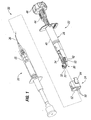
- FIGS 1 and 2 are perspective exploded and assembled views, respectively, of an insertion system 20 according to an embodiment of the invention.
- the insertion system 20 comprises an injector 22, a fluid guide or manifold 24, and a viscoelastic applicator 26.
- the exemplary injector 22 includes a handpiece 28 coupled to a distal nosepiece or cartridge 30, seen in an IOL transfer mode. In this mode, the cartridge 30 is in a position to receive an IOL (not shown) through a transfer interface 32.
- the cartridge 30 defines a cavity or load chamber 33 within for receiving the IOL, and also has an insertion tube 34 extending in the opposite direction than the transfer interface 32. A continuous path exists through the length of the cartridge 30 from the transfer interface 32, load chamber, and insertion tube 34.
- the injector 22 engages a case that contains an IOL, whereupon the IOL is automatically transferred to the cartridge 30.
- the IOL could be transferred manually into the cartridge 30.
- a lubricating agent Prior to transfer of the IOL into the cartridge 30, however, a lubricating agent will be introduced into the cartridge, and more particularly into a load chamber therein, as will be explained below.
- One exemplary viscoelastic applicator 26 is sold as the Healon® viscoelastic applicator by Advanced Medical Optics (AMO), Inc. of Santa Ana, California.
- the applicator 26 includes a syringe-like body 35 on the distal end of which is connected a thin cannula 36.
- the viscous medium within the body 35 may be expelled through the cannula 36, enabling good control of the precise location of delivery.
- IOL cartridges are quite small and the surfaces that require lubrication intricate, which makes the task of priming the cartridge quite intensive.
- lubricating agents other than viscoelastics are utilized, including Balanced Salt Solutions (BSS), and in the context of the present invention the viscoelastic applicator 26 is representative of lubricating agent applicators in general.
- BSS Balanced Salt Solutions
- a manifold that serves as an intermediary between the injector or cartridge and a lubricating agent applicator to facilitate and speed up the process of applying the lubricating agent to the load chamber.
- various kinds of injectors and cartridges are known, and manifolds that adapt to those designs are included in the scope of the invention.
- a common injector cartridge includes a hinged polymer structure in which the IOL is placed, originally termed a Bartell-style cartridge after its inventor. Folding the structure causes the IOL to fold as well, much like a taco.
- Such a system is primed first with the lubricating agent, such as using the applicator 26 shown in Figure 1 .
- IOL delivery systems would benefit from a fluid manifold as described herein, though the structural features of such manifolds would be different than the illustrated manifold 24 herein.
- Exemplary IOL delivery systems on the market that could use a manifold in accordance with the present invention include the AMO Emerald and Silver Series Unfolders, the Monarch line of Delivery Systems from Alcon Laboratories, Inc. of Fort Worth, Texas, the Mport, Microsert, Passport and SofPort model injectors from Bausch & Lomb (B&L) of Rochester, New York, and the MicroSTAAR injectors from STAAR Surgical Company of Monrovia, California.
- any manifold for use with these various insertion systems will provide at least one inlet port that when mated with the injector leads to the load chamber such that a lubricating agent injected into the inlet port is guided into appropriate surfaces of the load chamber.
- the manifold may be viewed as a guide of sorts for the delivery tips of various lubricating agent applicators.
- the illustrated applicator 26 has a relatively long and thin cannula 36 which is guided by the manifold 24 to the proper locations within the cartridge load chamber.
- Other applicators such as the B&L OcuCoat ® Viscoelastic, may have a somewhat blunter tip which a manifold of the present invention may be configured to receive.
- a manifold adapted to mate with BSS applicators would be useful.
- the injector handpiece 28 has a proximal end and a distal end to which the cartridge 30 couples.
- the handpiece 28 includes a generally tubular barrel 40 having a pair of bifurcated brackets 42 on a distal end thereof for retaining the cartridge 30.
- a plunger 44 translates longitudinally within the barrel 40.
- the plunger 44 comprises a shaft-like member with a drive cap 46 fixed on a proximal end thereof, and a distal end that engages a pushrod (not shown).
- the pushrod terminates at its distal end in a bifurcated tip that contacts and urges the IOL from the injector during the implant procedure.
- the cartridge 30 moves relative to the handpiece from the IOL transfer mode shown in Figure 1 to a delivery mode, such as by rotating 180° about the brackets 42.
- the IOL transfer mode defines a first position of the cartridge 30 for loading the IOL in which the transfer interface 32 faces away from the handpiece 28.
- the delivery mode defines a second position for delivering the IOL into the subject's eye wherein the insertion tube 34 faces away from the handpiece 28 in the second position. Further details of this arrangement are disclosed in U.S. Patent Publication 2006/0184181 .
- the lubricating agent is applied when the cartridge 30 is in its first position as shown in Figures 1 and 2 .
- the exemplary injector 22 is desirably packaged with the cartridge 30 in the first position.
- the fluid manifold 24 may be packaged on the end of the injector 22 as shown in Figure 2 , or as a separate item.
- the transfer interface 32 presents an opening to the load chamber 33 within the cartridge 30.
- the load chamber 33 commences at the transfer interface 32 with a pair of opposed longitudinal grooves for receiving side edges of the optic of the IOL.
- the fluid manifold 24 is designed to mate closely with the transfer interface 32 and includes a pair of conically recessed inlet ports 50 formed in an outer face 52 leading to internal channels (not shown) within the manifold.
- the internal channels are shaped and positioned such that a lubricating agent injected into the inlet ports 50 is guided thereby into the appropriate spaces within the load chamber 33. More specifically, the internal channels of the manifold 24 guide the lubricating agent into the two opposed grooves of the load chamber.
- Two inlet ports 50 are shown which lead to two internal channels to separately lubricate the longitudinal grooves. However, it is possible to provide just one inlet port which diverges within the manifold 24 toward the separate grooves.
- Figure 2 illustrates usage of the viscoelastic applicator 26 to lubricate one of the grooves within the load chamber 33 through one of the inlet ports 50. More details with regard to the internal channels of the fluid manifold 24 will be provided below.
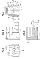
- Figures 3 and 4 show a preferred embodiment of a fluid manifold 24 for engagement with the exemplary injector 22.
- the upper and lower perspective views are looking at the manifold 24 from the end opposite the outer face 52 ( Figure 1 ), which is the end that mates with the injector 22.
- a three-sided peripheral wall 54 longitudinally projects away from the outer face 52 in an upside down U-shape.
- a lower wall 56 also projects away from the end wall, though not as far as the peripheral wall 54, and is interrupted by a lower rail 58.
- the peripheral wall 54 and lower wall 56 together define a generally rectilinear cavity 60 within the manifold 24 that receives and mates with the cartridge 30 of the injector 22.
- the manifold 24 defines structure within the cavity 60 that aligns features therein with the transfer interface 32 and load chamber 33 of the cartridge 30.
- Figure 5 shows an elevation looking directly at the outer face 52, and the height and spacing of the two conically recessed inlet ports 50.
- Figure 7 is an opposite elevation looking directly into the cavity 60 with the inlet ports 50 seen as mere pinholes.
- Figures 3-4 and 7 best show a central wall projecting longitudinally from the outer face 52 into the cavity 60.
- the central wall is formed partly by the lower rail 58, and also by an upper rail 62 and a middle rail 64.
- the lower and upper rails 58, 62 extend as far as the peripheral wall 54, and the middle rail 64 is recessed therefrom, as also seen in cross-section in Figure 8 .
- the resulting structure receives the cartridge 30 so that the transfer interface 32 extends fully into the cavity 60 and against the inside of the outer face 52.
- FIG. 9 shows one of the longitudinal grooves 70 of the load chamber 33 aligned with the lower inlet port 50, while the thin cannula 36 of the viscoelastic applicator 26 projects through the upper inlet port and is shown after having deposited a mass of lubricating agent.
- the two longitudinal grooves 70 gradually converge to the right and eventually transition into a tubular delivery channel (not shown) within the insertion tube 34 ( Figure 1 ).
- the delivery channel has a distal linear section adjacent its tip and tapers gradually wider toward the load chamber 33.
- the tapered delivery channel compresses and forms the IOL into an elongated and/or folded configuration suitable for delivery into the eye.
- the operator desirably applies lubricating agent along the grooves 70 and at least partway into the tubular delivery channel.
- the two longitudinal grooves 70 are separated at the transfer interface 32 and for a distance until joined at a bridge 72.
- the bridge 72 in this embodiment forms a floor of the load chamber 33, and continues toward the tubular delivery channel.
- the split nature of the longitudinal grooves 70 is particular to the illustrated cartridge 30, which is designed to engage a case that holds an IOL and receive the IOL therefrom in an automatic process without forceps.
- the inner features of the manifold 24 are specifically designed to accommodate the split grooves 70 and bridge 72. Namely, the lower and upper rails 58, 62 extend past the bridge 72 while the middle rail 64 contacts the bridge as shown.
- the combined central wall therefore segregates opposite sides of the load chamber 33 for a distance toward the tubular delivery channel, thus ensuring that lubricating agent injected into one of the inlet ports 50 is applied to the corresponding side of the load chamber.
- Figures 9 and 10 also illustrate the distal end of the bifurcated brackets 42 of the handpiece 28 that hold the cartridge 30.
- the peripheral wall 54 includes outwardly stepped wings 80 on either side that snap around the brackets 42.
- each bracket 42 features a small bump 82 ( Figure 1 ) on its exterior that snaps into a like sized hole 84 in the respective wing 80.
- the brackets 42 extend all the way to the inside end of the wings 80, as seen in Figures 9 and 10 .
- the injector 22 and manifold 24 desirably include complementary structural features that positively engage when they mate to indicate full engagement, such as the pin and hole embodiment that produces an audible and tactile click as feedback.
- the preceding fluid manifold 24 receives the cartridge 30 and mates against the transfer interface 32 thereon. No part of the manifold 24 extends past the transfer interface 32 into the load chamber 33, although such an extension is not incompatible with the purpose of the manifold.
- the manifold 24 is thus designed to remain external to the load chamber 33 when fully mated with the injector 22.
- Figures 11-16 illustrate several variations of a lubricating agent manifold that fits within the load chamber. Such variations do not form embodiments of the present invention.
- Figures 11 and 12 show the cartridge 30 from the top and end views with an exemplary internal manifold 100 therein. As seen from the top, the manifold 100 fits partway into the load chamber 33 with only a handle 102 remaining on the outside.
- Fig. 12 shows the size of the manifold 100 relative to the load chamber 33. Using the handle 102, the operator places the manifold 100 into the load chamber and applies a lubricating agent to an inlet port 104.
- Fig. 11 also shows exemplary contours of an internal tubular delivery channel 106 of the cartridge 30 that extends through the insertion tube 34.
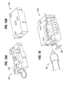
- Figures 13A and 13B show top and bottom manifold halves 110, 112 that can be combined into an internal manifold.
- Figure 14 illustrates the internal manifold 100 which may be formed with the top and bottom halves 110, 112, though an alternative handle 114 is seen in Figure 13 A .
- the handle 114 is solid, while the handle 102 is an open loop, but otherwise like parts will be given like numbers.
- the top and bottom halves 110, 112 each are formed as a block-shaped member with internal channels 120 on one face. As the reader will see, flipping the top half 110 over onto the bottom half 112 registers the respective internal channels and forms the structure of Figure 14 .
- Each internal channel 120 commences at the inlet port 104 and diverges around an island 122.
- the separated channels 120 pass side openings 124 and then converge at an end opening 126.
- One island 122 has a non-circular pin 130 and the other has a non-circular recess 132 to ensure the halves 110, 112 align and cannot rotate with one another.
- Figure 14 shows the assembled manifold 100 and schematically illustrates the path of lubricating agent therethrough having been injected from an applicator 26. Note that no thin cannula is required as the internal channel 120 directs the single input to the sides and end, corresponding to the longitudinal grooves 70 of the load chamber 33 as well as the delivery channel 106. In this respect the internal manifold 100 provides greater control of the lubricating agent flow than the external manifold 24 described above.
- FIGs 15A and 15B illustrate two halves 140, 142 of an alternative manifold 144, assembled with a T-handle 146 in Figure 16 .
- the internal channels 120 are only provided on one half, in this case the bottom half 140.
Landscapes
- Health & Medical Sciences (AREA)
- Ophthalmology & Optometry (AREA)
- Engineering & Computer Science (AREA)
- Public Health (AREA)
- Animal Behavior & Ethology (AREA)
- Veterinary Medicine (AREA)
- Biomedical Technology (AREA)
- Heart & Thoracic Surgery (AREA)
- Vascular Medicine (AREA)
- Life Sciences & Earth Sciences (AREA)
- General Health & Medical Sciences (AREA)
- Transplantation (AREA)
- Cardiology (AREA)
- Oral & Maxillofacial Surgery (AREA)
- Mechanical Engineering (AREA)
- Nuclear Medicine, Radiotherapy & Molecular Imaging (AREA)
- Surgery (AREA)
- Prostheses (AREA)
Claims (12)
- System (20) zur Abgabe einer Intraokularlinse (IOL) in das Auge eines Patienten, umfassend:einen IOL-Injektor (22), der einen Einführungsschlauch (34) und eine Ladekammer (33) zur Aufnahme einer IOL definiert, wobei der Injektor ferner eine Schubstange aufweist, die durch die Ladekammer bewegt werden kann,um die IOL in einem Abgabevorgang aus der Ladekammer und durch den Einführungsschlauch zu drücken, worin der Injektor ein Handstück (28) aufweist, das mit einer die Ladekammer definierenden Kartusche (30) verbunden ist,und die Kartusche bezüglich des Handstücks zwischen einer ersten Stellung zum Laden der Intraokularlinse und einer zweiten Stellung zur Abgabe der Intraokularlinse in das Auge des Patienten bewegt werden kann, und worin eine Transferschnittstelle (32) der Kartusche, die zur Ladekammer hin offen ist, in der ersten Stellung vom Handstück weg weist und der Einführungsschlauch in der zweiten Stellung vom Handstück weg weist; undeinen Flüssigkeitsverteiler (24), der zur Verbindung mit dem Injektor geformt ist und zumindest eine Einlassöffnung (50) aufweist, die nach der Verbindung mit dem Injektor zu der Ladekammer führt, so dass ein in die Einlassöffnung gespritztes Gleitmittel automatisch auf die mit der IOL in Berührung kommenden Oberflächen in der Ladekammer geleitet wird, dadurch gekennzeichnet, dass der Flüssigkeitsverteiler so geformt ist, dass er mit der Transferschnittstelle der Kartusche in der ersten Stellung verbunden werden kann, undworin die Ladekammer zumindest zwei beabstandete Oberflächen aufweist, welche die IOL berühren, und der Flüssigkeitsverteiler zumindest zwei separate Einlassöffnungen aufweist, die jeweils zu einer anderen beabstandeten Oberfläche führen.
- System (20) zur Abgabe einer Intraokularlinse (IOL) in das Augen eines Patienten, umfassend:einen IOL-Injektor (22), der einen Einführungsschlauch (34) und eine Ladekammer (33) zur Aufnahme einer IOL definiert, wobei der Injektor ferner eine Schubstange aufweist, die durch die Ladekammer bewegt werden kann, um die IOL in einem Abgabevorgang aus der Ladekammer und durch den Einführungsschlauch zu drücken, worin der Injektor ein Handstück (28) aufweist, das mit einer die Ladekammer definierenden Kartusche (30) verbunden ist, und die Kartusche bezüglich des Handstücks zwischen einer ersten Stellung zum Laden der Intraokularlinse und einer zweiten Stellung zur Abgabe der Intraokularlinse in das Auge des Patienten bewegt werden kann, und worin eine Transferschnittstelle (32) der Kartusche, die zur Ladekammer hin offen ist, in der ersten Stellung vom Handstück weg weist und der Einführungsschlauch in der zweiten Stellung vom Handstück weg weist; undeinen Flüssigkeitsverteiler (24), der zur Verbindung mit dem Injektor geformt ist und zumindest eine Einlassöffnung (50) aufweist, die nach der Verbindung mit dem Injektor zu der Ladekammer führt, so dass ein in die Einlassöffnung gespritztes Gleitmittel automatisch auf die mit der IOL in Berührung kommenden Oberflächen in der Ladekammer geleitet wird, dadurch gekennzeichnet, dass der Flüssigkeitsverteiler so geformt ist, dass er mit der Transferschnittstelle der Kartusche in der ersten Stellung verbunden werden kann, undworin die Ladekammer zumindest zwei beabstandete Oberflächen aufweist, welche die IOL berühren, und der Flüssigkeitsverteiler zumindest zwei Innenkanäle und nur eine mit den beiden Innenkanälen in Verbindung stehende Einlassöffnung aufweist.
- System nach Anspruch 1 oder 2, worin der Flüssigkeitsverteiler nach Verbindung mit dem Injektor außerhalb der Ladekammer bleibt.
- System nach Anspruch 1, worin der Flüssigkeitsverteiler zumindest zwei Innenkanäle aufweist und die beiden Innenkanäle jeweils zu einem separaten Innenkanal führen.
- System nach Anspruch 1 oder 2, worin sich die Kartusche zwischen den ersten und zweiten Stellungen 180° um das Handstück dreht.
- System nach Anspruch 1 oder 2, worin der Flüssigkeitsverteiler und der Injektor komplementäre Konstruktionsmerkmale aufweisen, die positiv mit einer hörbaren oder fühlbaren Rückmeldung in Eingriff stehen, wenn der Verteiler mit dem Injektor verbunden ist, um vollen Eingriff anzuzeigen.
- Verfahren zur Herstellung eines Intraokularlinsen-Injektors zur Aufnahme einer IOL (Intraokularlinse), umfassend:Bereitstellung eines IOL-Injektors (22), der einen zu einer Ladekammer (33) offenen Einführungsschlauch (34) zur Aufnahme einer IOL definiert;Bereitstellung eines Flüssigkeitsverteilers (24), der zur Verbindung mit dem Injektor geformt ist und zumindest eine Einlassöffnung (50) aufweist;Verbindung des Flüssigkeitsverteilers mit der Kartusche;Einspritzen eines Gleitmittels in die Einlassöffnung, so dass der Verteiler das Gleitmittel automatisch auf die mit der IOL in Berührung kommenden Oberflächen in der Ladekammer leitet;worin der Injektor ein Handstück (28) aufweist, das mit einer die Ladekammer definierenden Kartusche (30) verbunden ist, und wobei das Verfahren ferner die Platzierung der Kartusche in einer ersten Stellung bezüglich des Handstücks zur Verbindung mit dem Flüssigkeitsverteiler und dann die Bewegung der Kartusche in eine zweite Stellung bezüglich des Handstücks nach Lösen des Flüssigkeitsverteilers zur Abgabe der IOL in das Auge eines Patienten aufweist;worin eine Transferschnittstelle (32) der Kartusche in der ersten Stellung vom Handstück weg weist und der Einführungsschlauch in der zweiten Stellung vom Handstück weg weist, wobei der Flüssigkeitsverteiler zur Verbindung mit der Transferschnittstelle der Kartusche in der ersten Stellung geformt ist; undworin die Ladekammer zumindest zwei beabstandete Oberflächen aufweist, die die IOL berühren, und der Flüssigkeitsverteiler zumindest zwei separate Einlassteile aufweist, die jeweils zu einer anderen beabstandeten Oberfläche führen.
- Verfahren zur Herstellung eines Intraokularlinsen-Injektors zur Aufnahme einer IOL (Intraokularlinse), umfassend:Bereitstellung eines IOL-Injektors (22), der einen zu einer Ladekammer (33) offenen Einführungsschlauch (34) zur Aufnahme einer IOL definiert;Bereitstellung eines Flüssigkeitsverteilers (24), der zur Verbindung mit dem Injektor geformt ist und zumindest eine Einlassöffnung (50) aufweist;Verbindung des Flüssigkeitsverteilers mit der Kartusche;Einspritzen eines Gleitmittels in die Einlassöffnung, so dass der Verteiler das Gleitmittel automatisch auf die mit der IOL in Berührung kommenden Oberflächen in der Ladekammer leitet;worin der Injektor ein Handstück (28) aufweist, das mit einer die Ladekammer definierenden Kartusche (30) verbunden ist, und wobei das Verfahren ferner die Platzierung der Kartusche in einer ersten Stellung bezüglich des Handstücks zur Verbindung mit dem Flüssigkeitsverteiler und dann die Bewegung der Kartusche in eine zweite Stellung bezüglich des Handstücks nach Lösen des Flüssigkeitsverteilers zur Abgabe der IOL in das Auge eines Patienten aufweist;worin eine Transferschnittstelle (32) der Kartusche in der ersten Stellung vom Handstück weg weist und der Einführungsschlauch in der zweiten Stellung vom Handstück weg weist, wobei der Flüssigkeitsverteiler zur Verbindung mit der Transferschnittstelle der Kartusche in der ersten Stellung geformt ist; undworin die Ladekammer zumindest zwei beabstandete Oberflächen aufweist, die die IOL berühren, und der Flüssigkeitsverteiler zumindest zwei Innenkanäle und nur eine mit den beiden Innenkanälen in Verbindung stehende Einlassöffnung aufweist, wobei das Verfahren das Einspritzen des Gleitmittels durch die Einlassöffnung umfasst.
- Verfahren nach Anspruch 7 oder 8, worin der Einführungsschlauch auf der Kartusche definiert ist und sich die Kartusche zwischen den ersten und zweiten Stellungen 180° um das Handstück dreht.
- Verfahren nach Anspruch 7, worin der Flüssigkeitsverteiler zumindest zwei Innenkanäle aufweist und die beiden Innenkanäle jeweils zu einem separaten Innenkanal führen, wobei das Verfahren das separate Einspritzen des Gleitmittels in die beiden Einlassöffnungen umfasst.
- Verfahren nach Anspruch 7 oder 8, worin der Flüssigkeitsverteiler nach Verbindung mit dem Injektor außerhalb der Ladekammer bleibt.
- Verfahren nach Anspruch 7 oder 8, worin der Flüssigkeitsverteiler und der Injektor komplementäre Konstruktionsmerkmale aufweisen, die positiv mit einer hörbaren oder fühlbaren Rückmeldung in Eingriff stehen, wenn der Verteiler mit dem Injektor verbunden ist, um vollen Eingriff anzuzeigen.
Applications Claiming Priority (2)
| Application Number | Priority Date | Filing Date | Title |
|---|---|---|---|
| US11/779,217 US8398651B2 (en) | 2007-07-17 | 2007-07-17 | Viscoelastic applicator for IOL insertion apparatus |
| PCT/US2008/070200 WO2009012321A1 (en) | 2007-07-17 | 2008-07-16 | Viscoelastic applicator for iol insertion apparatus |
Publications (2)
| Publication Number | Publication Date |
|---|---|
| EP2166985A1 EP2166985A1 (de) | 2010-03-31 |
| EP2166985B1 true EP2166985B1 (de) | 2014-04-09 |
Family
ID=39739827
Family Applications (1)
| Application Number | Title | Priority Date | Filing Date |
|---|---|---|---|
| EP08826348.8A Active EP2166985B1 (de) | 2007-07-17 | 2008-07-16 | Viskoelastischer applikator für eine vorrichtung zum einsetzen von intraokularlinsen |
Country Status (5)
| Country | Link |
|---|---|
| US (4) | US8398651B2 (de) |
| EP (1) | EP2166985B1 (de) |
| AU (1) | AU2008276101B2 (de) |
| CA (1) | CA2693445C (de) |
| WO (1) | WO2009012321A1 (de) |
Cited By (1)
| Publication number | Priority date | Publication date | Assignee | Title |
|---|---|---|---|---|
| DE102020109867A1 (de) | 2020-04-08 | 2021-10-14 | Carl Zeiss Meditec Ag | Intraokularlinsen-Injektor mit spezifischer Einstechspitze einer Hohlnadel |
Families Citing this family (17)
| Publication number | Priority date | Publication date | Assignee | Title |
|---|---|---|---|---|
| CN101754728B (zh) * | 2007-07-23 | 2013-09-18 | 力景公司 | 晶状体递送系统 |
| US8968396B2 (en) | 2007-07-23 | 2015-03-03 | Powervision, Inc. | Intraocular lens delivery systems and methods of use |
| WO2012006616A2 (en) | 2010-07-09 | 2012-01-12 | Powervision, Inc. | Intraocular lens delivery devices and methods of use |
| CN102151194B (zh) * | 2011-01-31 | 2013-08-14 | 爱博诺德(北京)医疗科技有限公司 | 可预装粘弹剂的人工晶体预装式注射器 |
| JP6071995B2 (ja) | 2011-03-24 | 2017-02-01 | パワーヴィジョン・インコーポレーテッド | 眼内レンズ装填システムおよび使用方法 |
| PT2854708T (pt) | 2012-06-04 | 2017-01-17 | Alcon Pharmaceuticals Ltd | Dispositivo de inserção de lentes oculares e método de libertação de uma lente ocular a partir de um cartucho |
| EP2858593B1 (de) | 2012-06-12 | 2020-09-30 | Alcon Inc. | Intraokularer gasinjektor |
| EP3785668A1 (de) | 2013-03-15 | 2021-03-03 | Alcon Inc. | Aufbewahrungs- und ladevorrichtung für intraokularlinsen und verfahren zur verwendung |
| WO2015154049A1 (en) | 2014-04-04 | 2015-10-08 | Altaviz, Llc | Intraocular lens inserter |
| US10172706B2 (en) | 2015-10-31 | 2019-01-08 | Novartis Ag | Intraocular lens inserter |
| US11000367B2 (en) | 2017-01-13 | 2021-05-11 | Alcon Inc. | Intraocular lens injector |
| US10426602B2 (en) * | 2017-10-05 | 2019-10-01 | Ast Products, Inc. | Intraocular lens (IOL) injector and method of use thereof |
| US10925722B2 (en) * | 2018-04-26 | 2021-02-23 | Visioncare Inc. | Apparatus for use in implanting intraocular lenses and method of preparing apparatus for use |
| US20190328507A1 (en) * | 2018-04-26 | 2019-10-31 | Visioncare Inc. | Apparatus for use in implanting intraocular lenses and method of preparing apparatus for use |
| US11224537B2 (en) | 2018-10-19 | 2022-01-18 | Alcon Inc. | Intraocular gas injector |
| USD920519S1 (en) | 2019-06-28 | 2021-05-25 | Oertli-Instrumente Ag | Medical instrument for eye surgical purposes |
| WO2025193952A1 (en) * | 2024-03-13 | 2025-09-18 | The Johns Hopkins University | Systems and methods for visualizing ophthalmic viscosurgical device during and following ocular surgery and viscosurgery |
Family Cites Families (14)
| Publication number | Priority date | Publication date | Assignee | Title |
|---|---|---|---|---|
| DE69531283T2 (de) | 1994-08-05 | 2004-04-22 | Bausch & Lomb, Inc., Claremont | Vorrichtung zum einsetzen einer flexiblen intraokularen linse |
| US5735858A (en) | 1996-01-26 | 1998-04-07 | Allergan | IOL insertion apparatus and method for using same |
| AU731944B2 (en) * | 1997-12-29 | 2001-04-05 | Duckworth & Kent Limited | Injectors for intraocular lenses |
| US6387101B1 (en) | 1999-10-22 | 2002-05-14 | Staar Surgical Company, Inc. | Deformable intraocular lens injecting apparatus and method |
| US7615056B2 (en) | 2003-02-14 | 2009-11-10 | Visiogen, Inc. | Method and device for compacting an intraocular lens |
| US7156854B2 (en) * | 2003-05-28 | 2007-01-02 | Alcon, Inc. | Lens delivery system |
| US7429263B2 (en) | 2003-08-28 | 2008-09-30 | Bausch & Lomb Incorporated | Preloaded IOL injector |
| WO2005030097A1 (en) * | 2003-09-26 | 2005-04-07 | Bausch & Lomb Incorporated | Preloaded iol injector and method of packaging |
| US20060064112A1 (en) * | 2004-09-08 | 2006-03-23 | Edward Perez | Ocular device applicator |
| US20060052796A1 (en) * | 2004-09-08 | 2006-03-09 | Edward Perez | Combined epithelial delaminator and inserter |
| ATE514395T1 (de) * | 2004-12-29 | 2011-07-15 | Bausch & Lomb | Methode zur vorbereitung eines vorbeladenen intraokularlinseninjektors |
| US8562674B2 (en) | 2005-02-11 | 2013-10-22 | Abbott Medical Optics Inc. | Front loading IOL insertion apparatus and method of using |
| EP1800623A1 (de) * | 2005-12-20 | 2007-06-27 | Canon-Staar Co., Inc. | Einsetzvorrichtung für Intraokularlinse |
| US8460375B2 (en) * | 2006-08-14 | 2013-06-11 | Novartis Ag | Lens delivery system |
-
2007
- 2007-07-17 US US11/779,217 patent/US8398651B2/en active Active
-
2008
- 2008-07-16 AU AU2008276101A patent/AU2008276101B2/en not_active Ceased
- 2008-07-16 EP EP08826348.8A patent/EP2166985B1/de active Active
- 2008-07-16 CA CA2693445A patent/CA2693445C/en active Active
- 2008-07-16 WO PCT/US2008/070200 patent/WO2009012321A1/en not_active Ceased
-
2013
- 2013-03-08 US US13/790,345 patent/US9220592B2/en active Active
-
2015
- 2015-12-22 US US14/979,361 patent/US20160135990A1/en not_active Abandoned
-
2018
- 2018-11-16 US US16/194,191 patent/US10912674B2/en active Active
Cited By (2)
| Publication number | Priority date | Publication date | Assignee | Title |
|---|---|---|---|---|
| DE102020109867A1 (de) | 2020-04-08 | 2021-10-14 | Carl Zeiss Meditec Ag | Intraokularlinsen-Injektor mit spezifischer Einstechspitze einer Hohlnadel |
| DE102020109867B4 (de) | 2020-04-08 | 2023-08-31 | Carl Zeiss Meditec Ag | Intraokularlinsen-Injektor mit spezifischer Einstechspitze einer Hohlnadel |
Also Published As
| Publication number | Publication date |
|---|---|
| AU2008276101A1 (en) | 2009-01-22 |
| EP2166985A1 (de) | 2010-03-31 |
| US20190083309A1 (en) | 2019-03-21 |
| US20160135990A1 (en) | 2016-05-19 |
| CA2693445C (en) | 2016-01-12 |
| CA2693445A1 (en) | 2009-01-22 |
| US20130185915A1 (en) | 2013-07-25 |
| US10912674B2 (en) | 2021-02-09 |
| US8398651B2 (en) | 2013-03-19 |
| US20090024136A1 (en) | 2009-01-22 |
| WO2009012321A1 (en) | 2009-01-22 |
| AU2008276101B2 (en) | 2013-11-28 |
| US9220592B2 (en) | 2015-12-29 |
Similar Documents
| Publication | Publication Date | Title |
|---|---|---|
| US10912674B2 (en) | Viscoelastic applicator for IOL insertion apparatus | |
| US9017400B2 (en) | Rapid exchange IOL insertion apparatus and methods of using | |
| US8673002B2 (en) | Medical tools for facilitating keratoplasty and related methods | |
| EP4005531B1 (de) | Einführsystem für intraokularlinsen | |
| US12156805B2 (en) | Hydraulic delivery of surgical implants | |
| US20250177123A1 (en) | Hydraulic delivery of surgical implants | |
| US12433741B2 (en) | Haptic management for delivery of intraocular implants | |
| KR20250036054A (ko) | 수술용 임플란트의 유압식 전달 |
Legal Events
| Date | Code | Title | Description |
|---|---|---|---|
| PUAI | Public reference made under article 153(3) epc to a published international application that has entered the european phase |
Free format text: ORIGINAL CODE: 0009012 |
|
| 17P | Request for examination filed |
Effective date: 20100115 |
|
| AK | Designated contracting states |
Kind code of ref document: A1 Designated state(s): AT BE BG CH CY CZ DE DK EE ES FI FR GB GR HR HU IE IS IT LI LT LU LV MC MT NL NO PL PT RO SE SI SK TR |
|
| AX | Request for extension of the european patent |
Extension state: AL BA MK RS |
|
| DAX | Request for extension of the european patent (deleted) | ||
| 17Q | First examination report despatched |
Effective date: 20120731 |
|
| GRAP | Despatch of communication of intention to grant a patent |
Free format text: ORIGINAL CODE: EPIDOSNIGR1 |
|
| INTG | Intention to grant announced |
Effective date: 20131114 |
|
| GRAS | Grant fee paid |
Free format text: ORIGINAL CODE: EPIDOSNIGR3 |
|
| GRAA | (expected) grant |
Free format text: ORIGINAL CODE: 0009210 |
|
| AK | Designated contracting states |
Kind code of ref document: B1 Designated state(s): AT BE BG CH CY CZ DE DK EE ES FI FR GB GR HR HU IE IS IT LI LT LU LV MC MT NL NO PL PT RO SE SI SK TR |
|
| REG | Reference to a national code |
Ref country code: GB Ref legal event code: FG4D |
|
| REG | Reference to a national code |
Ref country code: CH Ref legal event code: EP Ref country code: AT Ref legal event code: REF Ref document number: 660897 Country of ref document: AT Kind code of ref document: T Effective date: 20140415 |
|
| REG | Reference to a national code |
Ref country code: IE Ref legal event code: FG4D |
|
| REG | Reference to a national code |
Ref country code: DE Ref legal event code: R096 Ref document number: 602008031436 Country of ref document: DE Effective date: 20140522 |
|
| REG | Reference to a national code |
Ref country code: NL Ref legal event code: T3 |
|
| REG | Reference to a national code |
Ref country code: AT Ref legal event code: MK05 Ref document number: 660897 Country of ref document: AT Kind code of ref document: T Effective date: 20140409 |
|
| REG | Reference to a national code |
Ref country code: LT Ref legal event code: MG4D |
|
| PG25 | Lapsed in a contracting state [announced via postgrant information from national office to epo] |
Ref country code: NO Free format text: LAPSE BECAUSE OF FAILURE TO SUBMIT A TRANSLATION OF THE DESCRIPTION OR TO PAY THE FEE WITHIN THE PRESCRIBED TIME-LIMIT Effective date: 20140709 Ref country code: LT Free format text: LAPSE BECAUSE OF FAILURE TO SUBMIT A TRANSLATION OF THE DESCRIPTION OR TO PAY THE FEE WITHIN THE PRESCRIBED TIME-LIMIT Effective date: 20140409 Ref country code: GR Free format text: LAPSE BECAUSE OF FAILURE TO SUBMIT A TRANSLATION OF THE DESCRIPTION OR TO PAY THE FEE WITHIN THE PRESCRIBED TIME-LIMIT Effective date: 20140710 Ref country code: FI Free format text: LAPSE BECAUSE OF FAILURE TO SUBMIT A TRANSLATION OF THE DESCRIPTION OR TO PAY THE FEE WITHIN THE PRESCRIBED TIME-LIMIT Effective date: 20140409 Ref country code: BG Free format text: LAPSE BECAUSE OF FAILURE TO SUBMIT A TRANSLATION OF THE DESCRIPTION OR TO PAY THE FEE WITHIN THE PRESCRIBED TIME-LIMIT Effective date: 20140709 Ref country code: IS Free format text: LAPSE BECAUSE OF FAILURE TO SUBMIT A TRANSLATION OF THE DESCRIPTION OR TO PAY THE FEE WITHIN THE PRESCRIBED TIME-LIMIT Effective date: 20140809 |
|
| PG25 | Lapsed in a contracting state [announced via postgrant information from national office to epo] |
Ref country code: SE Free format text: LAPSE BECAUSE OF FAILURE TO SUBMIT A TRANSLATION OF THE DESCRIPTION OR TO PAY THE FEE WITHIN THE PRESCRIBED TIME-LIMIT Effective date: 20140409 Ref country code: PL Free format text: LAPSE BECAUSE OF FAILURE TO SUBMIT A TRANSLATION OF THE DESCRIPTION OR TO PAY THE FEE WITHIN THE PRESCRIBED TIME-LIMIT Effective date: 20140409 Ref country code: HR Free format text: LAPSE BECAUSE OF FAILURE TO SUBMIT A TRANSLATION OF THE DESCRIPTION OR TO PAY THE FEE WITHIN THE PRESCRIBED TIME-LIMIT Effective date: 20140409 Ref country code: ES Free format text: LAPSE BECAUSE OF FAILURE TO SUBMIT A TRANSLATION OF THE DESCRIPTION OR TO PAY THE FEE WITHIN THE PRESCRIBED TIME-LIMIT Effective date: 20140409 Ref country code: AT Free format text: LAPSE BECAUSE OF FAILURE TO SUBMIT A TRANSLATION OF THE DESCRIPTION OR TO PAY THE FEE WITHIN THE PRESCRIBED TIME-LIMIT Effective date: 20140409 Ref country code: LV Free format text: LAPSE BECAUSE OF FAILURE TO SUBMIT A TRANSLATION OF THE DESCRIPTION OR TO PAY THE FEE WITHIN THE PRESCRIBED TIME-LIMIT Effective date: 20140409 |
|
| PG25 | Lapsed in a contracting state [announced via postgrant information from national office to epo] |
Ref country code: PT Free format text: LAPSE BECAUSE OF FAILURE TO SUBMIT A TRANSLATION OF THE DESCRIPTION OR TO PAY THE FEE WITHIN THE PRESCRIBED TIME-LIMIT Effective date: 20140811 |
|
| REG | Reference to a national code |
Ref country code: DE Ref legal event code: R097 Ref document number: 602008031436 Country of ref document: DE |
|
| PG25 | Lapsed in a contracting state [announced via postgrant information from national office to epo] |
Ref country code: RO Free format text: LAPSE BECAUSE OF FAILURE TO SUBMIT A TRANSLATION OF THE DESCRIPTION OR TO PAY THE FEE WITHIN THE PRESCRIBED TIME-LIMIT Effective date: 20140409 Ref country code: CZ Free format text: LAPSE BECAUSE OF FAILURE TO SUBMIT A TRANSLATION OF THE DESCRIPTION OR TO PAY THE FEE WITHIN THE PRESCRIBED TIME-LIMIT Effective date: 20140409 Ref country code: BE Free format text: LAPSE BECAUSE OF FAILURE TO SUBMIT A TRANSLATION OF THE DESCRIPTION OR TO PAY THE FEE WITHIN THE PRESCRIBED TIME-LIMIT Effective date: 20140409 Ref country code: DK Free format text: LAPSE BECAUSE OF FAILURE TO SUBMIT A TRANSLATION OF THE DESCRIPTION OR TO PAY THE FEE WITHIN THE PRESCRIBED TIME-LIMIT Effective date: 20140409 Ref country code: EE Free format text: LAPSE BECAUSE OF FAILURE TO SUBMIT A TRANSLATION OF THE DESCRIPTION OR TO PAY THE FEE WITHIN THE PRESCRIBED TIME-LIMIT Effective date: 20140409 Ref country code: SK Free format text: LAPSE BECAUSE OF FAILURE TO SUBMIT A TRANSLATION OF THE DESCRIPTION OR TO PAY THE FEE WITHIN THE PRESCRIBED TIME-LIMIT Effective date: 20140409 |
|
| PLBE | No opposition filed within time limit |
Free format text: ORIGINAL CODE: 0009261 |
|
| STAA | Information on the status of an ep patent application or granted ep patent |
Free format text: STATUS: NO OPPOSITION FILED WITHIN TIME LIMIT |
|
| PG25 | Lapsed in a contracting state [announced via postgrant information from national office to epo] |
Ref country code: LU Free format text: LAPSE BECAUSE OF FAILURE TO SUBMIT A TRANSLATION OF THE DESCRIPTION OR TO PAY THE FEE WITHIN THE PRESCRIBED TIME-LIMIT Effective date: 20140716 |
|
| 26N | No opposition filed |
Effective date: 20150112 |
|
| PG25 | Lapsed in a contracting state [announced via postgrant information from national office to epo] |
Ref country code: IT Free format text: LAPSE BECAUSE OF FAILURE TO SUBMIT A TRANSLATION OF THE DESCRIPTION OR TO PAY THE FEE WITHIN THE PRESCRIBED TIME-LIMIT Effective date: 20140409 |
|
| REG | Reference to a national code |
Ref country code: IE Ref legal event code: MM4A |
|
| REG | Reference to a national code |
Ref country code: DE Ref legal event code: R097 Ref document number: 602008031436 Country of ref document: DE Effective date: 20150112 |
|
| REG | Reference to a national code |
Ref country code: FR Ref legal event code: PLFP Year of fee payment: 8 |
|
| PG25 | Lapsed in a contracting state [announced via postgrant information from national office to epo] |
Ref country code: SI Free format text: LAPSE BECAUSE OF FAILURE TO SUBMIT A TRANSLATION OF THE DESCRIPTION OR TO PAY THE FEE WITHIN THE PRESCRIBED TIME-LIMIT Effective date: 20140409 |
|
| PG25 | Lapsed in a contracting state [announced via postgrant information from national office to epo] |
Ref country code: IE Free format text: LAPSE BECAUSE OF NON-PAYMENT OF DUE FEES Effective date: 20140716 |
|
| PG25 | Lapsed in a contracting state [announced via postgrant information from national office to epo] |
Ref country code: MC Free format text: LAPSE BECAUSE OF FAILURE TO SUBMIT A TRANSLATION OF THE DESCRIPTION OR TO PAY THE FEE WITHIN THE PRESCRIBED TIME-LIMIT Effective date: 20140409 |
|
| REG | Reference to a national code |
Ref country code: FR Ref legal event code: PLFP Year of fee payment: 9 |
|
| PG25 | Lapsed in a contracting state [announced via postgrant information from national office to epo] |
Ref country code: MT Free format text: LAPSE BECAUSE OF FAILURE TO SUBMIT A TRANSLATION OF THE DESCRIPTION OR TO PAY THE FEE WITHIN THE PRESCRIBED TIME-LIMIT Effective date: 20140409 Ref country code: CY Free format text: LAPSE BECAUSE OF FAILURE TO SUBMIT A TRANSLATION OF THE DESCRIPTION OR TO PAY THE FEE WITHIN THE PRESCRIBED TIME-LIMIT Effective date: 20140409 |
|
| PG25 | Lapsed in a contracting state [announced via postgrant information from national office to epo] |
Ref country code: HU Free format text: LAPSE BECAUSE OF FAILURE TO SUBMIT A TRANSLATION OF THE DESCRIPTION OR TO PAY THE FEE WITHIN THE PRESCRIBED TIME-LIMIT; INVALID AB INITIO Effective date: 20080716 Ref country code: TR Free format text: LAPSE BECAUSE OF FAILURE TO SUBMIT A TRANSLATION OF THE DESCRIPTION OR TO PAY THE FEE WITHIN THE PRESCRIBED TIME-LIMIT Effective date: 20140409 |
|
| REG | Reference to a national code |
Ref country code: FR Ref legal event code: PLFP Year of fee payment: 10 |
|
| REG | Reference to a national code |
Ref country code: FR Ref legal event code: PLFP Year of fee payment: 11 |
|
| PGFP | Annual fee paid to national office [announced via postgrant information from national office to epo] |
Ref country code: CH Payment date: 20180713 Year of fee payment: 11 |
|
| REG | Reference to a national code |
Ref country code: CH Ref legal event code: PFA Owner name: JOHNSON AND JOHNSON SURGICAL VISION, INC., US Free format text: FORMER OWNER: ABBOTT MEDICAL OPTICS INC., US |
|
| REG | Reference to a national code |
Ref country code: DE Ref legal event code: R081 Ref document number: 602008031436 Country of ref document: DE Owner name: JOHNSON & JOHNSON SURGICAL VISION, INC. (N. D., US Free format text: FORMER OWNER: ABBOTT MEDICAL OPTICS INC., SANTA ANA, CALIF., US |
|
| REG | Reference to a national code |
Ref country code: NL Ref legal event code: HC Owner name: JOHNSON & JOHNSON SURGICAL VISION, INC.; US Free format text: DETAILS ASSIGNMENT: CHANGE OF OWNER(S), CHANGE OF OWNER(S) NAME; FORMER OWNER NAME: ABBOTT MEDICAL OPTICS INC. Effective date: 20181204 |
|
| REG | Reference to a national code |
Ref country code: CH Ref legal event code: PL |
|
| PG25 | Lapsed in a contracting state [announced via postgrant information from national office to epo] |
Ref country code: LI Free format text: LAPSE BECAUSE OF NON-PAYMENT OF DUE FEES Effective date: 20190731 Ref country code: CH Free format text: LAPSE BECAUSE OF NON-PAYMENT OF DUE FEES Effective date: 20190731 |
|
| PGFP | Annual fee paid to national office [announced via postgrant information from national office to epo] |
Ref country code: GB Payment date: 20220606 Year of fee payment: 15 |
|
| PGFP | Annual fee paid to national office [announced via postgrant information from national office to epo] |
Ref country code: FR Payment date: 20220609 Year of fee payment: 15 |
|
| GBPC | Gb: european patent ceased through non-payment of renewal fee |
Effective date: 20230716 |
|
| PG25 | Lapsed in a contracting state [announced via postgrant information from national office to epo] |
Ref country code: GB Free format text: LAPSE BECAUSE OF NON-PAYMENT OF DUE FEES Effective date: 20230716 |
|
| PG25 | Lapsed in a contracting state [announced via postgrant information from national office to epo] |
Ref country code: FR Free format text: LAPSE BECAUSE OF NON-PAYMENT OF DUE FEES Effective date: 20230731 |
|
| PGFP | Annual fee paid to national office [announced via postgrant information from national office to epo] |
Ref country code: NL Payment date: 20250613 Year of fee payment: 18 |
|
| PGFP | Annual fee paid to national office [announced via postgrant information from national office to epo] |
Ref country code: DE Payment date: 20250604 Year of fee payment: 18 |