EP2166372A1 - Mensch-Maschinen-Interface zur Pilotenunterstützung bei Start oder Landung eines Fluggeräts unter verminderter Außensicht - Google Patents
Mensch-Maschinen-Interface zur Pilotenunterstützung bei Start oder Landung eines Fluggeräts unter verminderter Außensicht Download PDFInfo
- Publication number
- EP2166372A1 EP2166372A1 EP08016676A EP08016676A EP2166372A1 EP 2166372 A1 EP2166372 A1 EP 2166372A1 EP 08016676 A EP08016676 A EP 08016676A EP 08016676 A EP08016676 A EP 08016676A EP 2166372 A1 EP2166372 A1 EP 2166372A1
- Authority
- EP
- European Patent Office
- Prior art keywords
- aircraft
- machine interface
- landing
- base plane
- man
- Prior art date
- Legal status (The legal status is an assumption and is not a legal conclusion. Google has not performed a legal analysis and makes no representation as to the accuracy of the status listed.)
- Granted
Links
Images



Classifications
-
- G—PHYSICS
- G01—MEASURING; TESTING
- G01C—MEASURING DISTANCES, LEVELS OR BEARINGS; SURVEYING; NAVIGATION; GYROSCOPIC INSTRUMENTS; PHOTOGRAMMETRY OR VIDEOGRAMMETRY
- G01C23/00—Combined instruments indicating more than one navigational value, e.g. for aircraft; Combined measuring devices for measuring two or more variables of movement, e.g. distance, speed or acceleration
-
- G—PHYSICS
- G01—MEASURING; TESTING
- G01S—RADIO DIRECTION-FINDING; RADIO NAVIGATION; DETERMINING DISTANCE OR VELOCITY BY USE OF RADIO WAVES; LOCATING OR PRESENCE-DETECTING BY USE OF THE REFLECTION OR RERADIATION OF RADIO WAVES; ANALOGOUS ARRANGEMENTS USING OTHER WAVES
- G01S13/00—Systems using the reflection or reradiation of radio waves, e.g. radar systems; Analogous systems using reflection or reradiation of waves whose nature or wavelength is irrelevant or unspecified
- G01S13/88—Radar or analogous systems specially adapted for specific applications
- G01S13/93—Radar or analogous systems specially adapted for specific applications for anti-collision purposes
- G01S13/933—Radar or analogous systems specially adapted for specific applications for anti-collision purposes of aircraft or spacecraft
- G01S13/935—Radar or analogous systems specially adapted for specific applications for anti-collision purposes of aircraft or spacecraft for terrain-avoidance
-
- G—PHYSICS
- G01—MEASURING; TESTING
- G01S—RADIO DIRECTION-FINDING; RADIO NAVIGATION; DETERMINING DISTANCE OR VELOCITY BY USE OF RADIO WAVES; LOCATING OR PRESENCE-DETECTING BY USE OF THE REFLECTION OR RERADIATION OF RADIO WAVES; ANALOGOUS ARRANGEMENTS USING OTHER WAVES
- G01S17/00—Systems using the reflection or reradiation of electromagnetic waves other than radio waves, e.g. lidar systems
- G01S17/88—Lidar systems specially adapted for specific applications
- G01S17/93—Lidar systems specially adapted for specific applications for anti-collision purposes
- G01S17/933—Lidar systems specially adapted for specific applications for anti-collision purposes of aircraft or spacecraft
Definitions
- the invention relates to a human-machine interface (MMI) for pilot support during take-off and landing of an aircraft, in particular a helicopter in a reduced external view or in restricted visibility conditions.
- MMI human-machine interface
- the sand or Staubaufwirbelung often causes the pilot loses the cockpit outside view in whole or in part - the so-called brown-out. Due to the loss of the external view, the pilot is at risk of losing the spatial orientation and this in particular with regard to pitch and / or roll angle as well as unwanted lateral drift of the aircraft. A similar effect can occur during landings in the snow. This effect is called white-out.
- Brown-Out MMI Essential for a universal, operationally suitable Brown-Out MMI is the intuitive communication of the above-mentioned characteristics and information to the pilot or pilots.
- a large amount of information is transmitted to the pilot in column-shaped bar and number columns. This can be in situations of extreme tension, like. e.g. during the Brown-Out, where it depends on very precise and very fast reaction to a changing flight situation - possibly lead to misinterpretation or even confusion by the pilot.
- any representation of the above-mentioned characteristics and information must be presented in a form that is intuitive and minimizes the burden on the pilot at this critical landing stage.
- the invention has for its object to improve a human-machine interface for pilots so that the pilot in a brown-out or white-out landing provides an optimized intuitive support in the spatial orientation and thus a safe landing and especially in these extreme situations.
- the pilot in particular the control of attitude with respect to pitch and roll position is much easier and he receives at the same time an impression of the height above ground.
- the impression of the current altitude can be further enhanced by continuously displaying a lot from the aircraft to the base plane.
- the base plane is superimposed on a three-dimensional representation of the real topographic terrain surface (in particular with regard to the conditions in front, laterally and below the aircraft) on the basis of high-resolution 3D data.
- the display concept according to the invention is able to prevent the spatial orientation loss in the brown-out case and also to allow an assessment of the desired landing or Aufsetzsees. Attitude, altitude above ground, and also instantaneous drift speed and direction are concentrated, presented in an intuitive manner for the pilot. It provides pilots with universal, operational-ready helicopter landing assistance especially under brown-out conditions.
- the MMI according to the invention is based on the use of a plurality of sensors (attitude and navigation system, one or more radar altimeters and / or laser altimeters) as basic configuration as well as additional laser-based charging systems, video or FLIR cameras and / or dust-penetrating radar systems as well as 3D digital terrain systems. and obstacle databases as an option).
- Fig. 1 shows a base plane BE as an essential component of the virtual scenario. It represents the idealized surface of the landing plane.
- the base plane BE is limited by the artificial horizon, which in principle has the same functionality as an attitude indicator in the cockpit. This is of essential importance for the presentation concept according to the invention, since the pilot can easily and intuitively read all attitude changes with respect to pitch and / or roll angles directly through the artificial horizon and the base plane BE connected to it.
- the better estimate of the current attitude as well as the qualitative altitude over ground can be on the At the base level additional escape and distance lines are drawn, which reinforce the impression of the spatial depth of the base level BE.
- All graphical elements of the base plane BE are updated using the current flight state data (attitude) and the current altitude above ground (AGL). This ensures that all changes in attitude and altitude over ground will immediately result in a corresponding change in the graphic display of the base level BE.
- Fig. 2 shows a possible expression of the virtual scenario with the base level BE, as represented by the MMI according to the invention.
- a corresponding representation of the attitude of the aircraft is also shown at the bottom right in the separate diagram.
- the virtual scenario shows a symbol F for the aircraft above the base plane BE, as viewed from a virtual observer behind the aircraft. He has the same attitude as the aircraft on. One can imagine the observer as rigidly connected to the aircraft. The pilot thus sees his aircraft flying from behind above the base plane BE taking into account the current flight condition data.
- This representation allows a very intuitive assessment of the pitch and roll angle of the aircraft and the height above ground.
- the representation of the drift velocity and direction (drift vector) over reason can be included.
- the input data for presentation are taken from an attitude and navigation system.
- the drift information can be represented as a perspective projection of the drift vector into the virtual base plane.
- the lateral and longitudinal vector component of the speed over ground with respect to the aircraft vectorially represented as a line or arrow of variable length.
- the current display length of the drift vector D within the virtual scenario is proportional to the speed in the horizontal plane and corresponds at all times to the actual drift speed and direction of the aircraft over ground.
- the perspective projection of a circle can additionally be superimposed on the base plane BE whose radius corresponds to a previously determined drift velocity (eg 10 knots) and whose center is the origin of the drift vector D.
- a previously determined drift velocity eg 10 knots
- An example of such a circle at the base level BE is in Fig. 3 also shown.
- Another functionality of the MMI according to the invention is the presentation of the current altitude above ground. On the one hand, this is implicitly shown by the representation of the aircraft above the base plane BE and can be explained by the additional representation of a lot L (FIG. Fig. 4 ) are supplemented by the aircraft at the base level BE, the solder then running from the aircraft to its perpendicular base on the base plane BE.
- FIG. 5 shows such a scenario in two snapshots at different altitude above ground.
- the associated shadows are labeled S1, S2. If the altitude drops above ground, the shadow moves closer to the foot of the lot. Whether the lot is shown or not is optional.
- the current sensor concepts for Brown-Out rescue systems assume that a necessary sensor is a dust-penetrating radar sensor.
- the spatial resolution of these sensors is usually rather coarse (resolution in azimuth direction ⁇ 2 °). They are therefore used as pure warning systems intended to represent when dangerous obstacles move into the landing area during brown-out or when the aircraft moves toward such obstacles due to unintentional drift within the cloud of dust.
- Such radar sensors are referred to in the literature as Electronic Bumper (electronic bumper).
- the information obtained with these radar sensors can be integrated into the representation in an advantageous embodiment of the invention (see Fig. 6 ).
- the proposed representation for the active warning of obstacles in the landing zone can be functionally similar to a car parking aid.
- the spatial projection of a specific sector Z on the base plane BE, in which an object was detected, is highlighted in color (hazard sector display). For example, 4, 8 or 16 sectors are available as lateral resolution. Since the Electronic Bumper usually gives little or no information about the actual height of the obstacle and there is an uncertainty in the distance measurement by projection, the distance representation is divided into a small number of discrete distance levels (eg 3 to 4 distance levels: distance between current position and 1/2 rotor diameter, between 1 ⁇ 2 and 1 rotor diameter, between 1 and 2 rotor diameters, more than 2 rotor diameters). For obstacles closer than a given multiple / fraction of the rotor diameter, an additional acoustic warning may be issued.
- discrete distance levels eg 3 to 4 distance levels: distance between current position and 1/2 rotor diameter, between 1 ⁇ 2 and 1 rotor diameter, between 1 and 2 rotor diameters, more than 2 rotor diameters.
- the Brown Out rescue system has a high-resolution, forward-looking 3D sensor or alternatively has access to a 3D digital terrain database, and the helicopter also has a helmet vision system (HMS / D), the specific landing site or landing point in the phase visually targeted by a pilot prior to a possible Brown-Out, selected and displayed accurately in the representation on the base level BE.
- HMS / D helmet vision system
- the 3D data of the area in front of the helicopter must be available, the HMS / D field of view (FOV) must be known, and a digital trigger input must be available.
- the pilot focuses this location in the landing zone with the HMS / D by aiming it through the cockpit window and then activating the digital trigger.
- the base level BE in this case corresponds to the real floor area and can be used directly for the described marking of the landing point.
- the Brown Out rescue system has a high resolution forward looking 3D sensor (ie, a range image sensor) and / or has access to the information of a 3D terrain and terrain digital database, then a 3D representation of the real topographic terrain and All non-ground objects are superimposed as a further presentation layer of the base level BE.
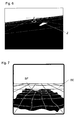
- Fig. 7 shows an example in which the base plane BE, a representation of the real floor surface BF is superimposed on the basis of 3D data.
- a basic level virtual scenario BE is shown superimposed on a real topographical bottom surface BF with raised non-ground objects (obstacles) H in the vicinity of the landing zone.
- the floor area BF and the obstacles are displayed in height-coded form, ie the colors / grayscale in the illustration correspond to the object heights in relation to the floor area. Due to the visualization of the ground surface BF according to the invention from the perspective of a subsequent observer, the area to the left / right as well as below the aircraft is generously represented here. Additionally is in Fig. 8 illustrates a Lot L on the bottom surface BF and a danger sector Z due to existing obstacles.
- All graphical elements of the 3D representation of the virtual scenario are updated using the current flight state data (attitude and velocity) and the current altitude above ground. This ensures that any changes in attitude, airspeed, drift direction, and altitude over ground will immediately cause a corresponding change in the 3D visualization of the virtual scenario without any noticeable time delay. It creates a kind of "virtual reality" impression - just as if there were no visual obstruction by the dust during the brown-out.
- This MMI concept conveys In combination of various individual components the pilot has a very intuitive and natural understanding of the current flight situation as well as a very realistic impression of the actual conditions in and around the landing zone.
- the representation of the virtual scenario plays an important role. In fact, this representation replaces the missing cockpit outside view in the brown-out case for the pilot.
- the 3D information for the ground surface BF and for the non-ground objects H can come from either a radar, an ultrasound system, a laser-based charger or other suitable active measuring systems in the aircraft. Likewise, this 3D information can be extracted and displayed from high-resolution 3D terrain and obstacle databases.
Landscapes
- Engineering & Computer Science (AREA)
- Radar, Positioning & Navigation (AREA)
- Remote Sensing (AREA)
- Physics & Mathematics (AREA)
- Aviation & Aerospace Engineering (AREA)
- General Physics & Mathematics (AREA)
- Electromagnetism (AREA)
- Computer Networks & Wireless Communication (AREA)
- Traffic Control Systems (AREA)
- Radar Systems Or Details Thereof (AREA)
- Toys (AREA)
- Instructional Devices (AREA)
- Processing Or Creating Images (AREA)
- Navigation (AREA)
- Optical Radar Systems And Details Thereof (AREA)
Abstract
Description
- Die Erfindung betrifft ein Mensch-Maschinen-Interface (MMI) zur Pilotenunterstützung bei Start und Landung eines Fluggeräts, insbesondere eines Helikopters bei verminderter Außensicht oder unter eingeschränkten Sichtbedingungen. In trockenen, wüstenartigen Gebieten (wie z.B. Afghanistan) kommt es bei fast jeder Außenlandung von Hubschraubern zu einer starken Aufwirbelung von Sand und Staub. Dies wird durch den sogenannten Down-Wash des Hauptrotors verursacht. Die Sand- bzw. Staubaufwirbelung führt oft dazu, dass der Pilot die Cockpit-Außensicht ganz oder teilweise verliert - dem so genannten Brown-Out. Durch den Verlust der Außensicht besteht für den Piloten die Gefahr des Verlustes der räumlichen Orientierung und dies insbesondere hinsichtlich Nick- und/oder Rollwinkel sowie ungewollter seitlicher Drift des Luftfahrzeugs. Zu einem ähnlichen Effekt kann es bei Landungen im Schnee kommen. Dieser Effekt wird als White-Out bezeichnet.
- In der
DE 10 2004 051 625 A1 ist eine Hubschrauberlandehilfe speziell für Brown-Out-Bedingungen beschrieben, bei dem während des Brown-Outs auf einem Display eine virtuelle 3D-Ansicht der Umgebung in der Perspektive des Piloten dargestellt wird, wobei die virtuelle Ansicht auf der Basis von 3D-Daten, die beim Landeanflug vor Einsetzen des Brown-Outs akkumuliert wurden, generiert wird. - In der
WO 2005/015333 A2 ist ebenfalls eine Hubschrauberlandehilfe für Brown-Out Bedingungen beschrieben, die zur Pilotenunterstützung mittels unterschiedlicher Sensoren erzeugte Umgebungsinformationen und Flugzustandsdaten kombiniert und mittels Hubschrauberdatenbus laufend aktualisiert. Dabei werden die Umgebungsinformationen einerseits und Flugzustandsdaten wie Geschwindigkeit, Bewegungs- und Driftrichtung und Höhe über Grund andererseits in einem gemeinsamen Display dargestellt. - Für den Piloten notwendige, bzw. hilfreiche Kenngrößen und Informationen für einen Landevorgang unter Brown-Out Bedingungen sind:
- a) die Höhe über Grund,
- b) die Lage des Luftfahrzeugs im Raum, bzw. zum Boden,
- c) die Bewegungsrichtung und Geschwindigkeit über Grund,
- d) Änderung der Geschwindigkeit über Grund,
- e) Änderung der Höhe über Grund,
- f) die Hindernissituation am Landeplatz,
- g) die Bodenbeschaffenheit des Lande- oder Aufsetzpunktes,
- h) die Entfernung und relative Richtung zu einem zuvor selbst ausgewählten Lande- oder Aufsetzpunkt.
- Wesentlich für ein universelles, operationell einsatztaugliches Brown-Out MMI ist die intuitive Vermittlung der oben angeführten Kenngrößen und Informationen an den oder die Piloten. Andererseits werden gerade in militärischen Hubschraubern eine Vielzahl an Informationen in spaltenförmigen Balken- und Zahlenkolonnen an den Piloten übermittelt. Dies kann in Situationen extremer Anspannung, wie. z.B. während des Brown-Outs, wo es auf sehr präzises und sehr schnelles Reagieren auf eine sich ändernde Flugsituation ankommt - evtl. zu Fehlinterpretationen oder gar Verwechslungen durch den Piloten führen. Aus diesem Grund muss jede Darstellung der oben angeführten Kenngrößen und Informationen in einer Form dargeboten werden, welche intuitiv ist und die Belastung des Piloten in dieser kritischen Phase der Landung minimiert.
- Der Erfindung liegt die Aufgabe zugrunde, ein Mensch-Maschinen-Interface für Piloten so zu verbessern, das dem Piloten bei einer Brown-Out- oder White-Out-Landung eine optimierte intuitive Unterstützung bei der räumlichen Orientierung bietet und somit eine sichere Landung auch und insbesondere in diesen Extremsituationen ermöglicht.
- Diese Aufgabe wird mit dem Gegenstand des Patentanspruch 1 gelöst. Vorteilhafte Ausführungen sind Gegenstand von Unteransprüchen.
- Das erfindungsgemäße Mensch-Maschinen-Interface ist in der Lage, ein virtuelles Szenario aus der Perspektive eines virtuellen Beobachters darzustellen, der sich hinter dem Fluggerät befindet und dieselbe Fluglage aufweist, wie das Fluggerät selbst. Das virtuelle Szenario weist die folgenden Komponenten auf:
- eine Basisebene, welche eine idealisierte Bodenfläche symbolisiert, berechnet aufgrund des momentanen Wertes der Flughöhe über Grund und der momentanen Fluglagedaten. Die Basisebene wird durch einen künstlichen Horizont begrenzt und wird mit den momentanen Flugzustandsdaten und der momentanen Höhe über Grund kontinuierlich aktualisiert,
- ein Symbol für das Fluggerät, dessen Position und Lage relativ zur Basisebene die tatsächliche, momentane Fluglage und Höhe über Grund (AGL) des Fluggeräts darstellt.
- Durch diese Darstellung wird dem Piloten insbesondere die Kontrolle der Fluglage hinsichtlich Nick- und Rolllage wesentlich erleichtert und er erhält gleichzeitig einen Eindruck von der Höhe über Grund.
- In die Basisebene oder einer hierzu parallelen Ebene können in vorteilhaften Ausführungen weitere Anzeigen projiziert werden:
- Driftvektor auf oder über der Basisebene zur Anzeige der momentanen Geschwindigkeit und Bewegungsrichtung über Grund,
- AGL-Indikator zur Visualisierung der momentanen Flughöhe über Grund,
- Schatten des Fluggeräts (basierend auf der Basis des aktuellen Sonnenstands oder einer fixen virtuellen Lichtquelle) zur zusätzlichen Visualisierung der momentanen Höhe über Grund,
- Gefahrensektor auf oder über der Basisebene zur Visualisierung von stationären oder sich bewegenden Hindernissen innerhalb des Sicherheitsbereiches der Landezone,
- vorgesehener Landeplatz oder Aufsetzpunkt, der vor dem Einsetzen des Brown-Outs durch numerische Positionseingabe oder mittels Helmsichtgerät, Fluglagedaten und einem digitalen Trigger ausgewählt wurde, und der in der Basisebene fortlaufend und positionsgenau dargestellt wird. In einer besonders vorteilhaften Ausführung können die 3D-Daten der Landezone in die Berechnung des Landesplatzes oder Aufsetzpunktes mit einbezogen werden.
- Damit stehen dem Piloten alle wichtigen Flug-, Hindernis- und Geländeinformationen innerhalb der Landezone in konzentrierter Form zur Verfügung, und er muss seine Aufmerksamkeit nicht auf verschiedene Anzeigegeräte oder Bildschirme aufteilen.
- Der Eindruck von der momentanen Flughöhe kann weiter verstärkt werden, in dem fortlaufend ein Lot vom Fluggerät auf die Basisebene dargestellt wird.
- In einer weiteren Ausführung wird der Basisebene eine dreidimensionale Darstellung der realen topographischen Geländeoberfläche (insbesondere bezüglich der Gegebenheiten vor, seitlich sowie unter dem Fluggerät) auf der Basis von hochauflösenden 3D-Daten überlagert.
- Das erfindungsgemäße Anzeigekonzept ist in der Lage, den räumlichen Orientierungsverlust im Brown-Out-Fall zu verhindern und zusätzlich eine Beurteilung des angestrebten Landeplatzes oder Aufsetzpunktes zu erlauben. Fluglage, Höhe über Grund und darüber hinaus auch momentane Driftgeschwindigkeit und -richtung werden konzentriert, in einer für den Piloten intuitiv nachvollziehbaren Weise dargestellt. Es stellt dem Piloten eine universelle, operationell einsatztaugliche Hilfestellung für Hubschrauberlandungen speziell unter Brown-Out-Bedingungen zur Verfügung. Das erfindungsgemäße MMI basiert auf der Verwendung mehrerer Sensoren (Fluglage- und Navigationssystem, ein oder mehrere Radarhöhenmesser und/oder Laserhöhenmesser) als Basiskonfiguration sowie zusätzliche laserbasierte Ladarsysteme, Video- bzw. FLIR-Kameras und/oder staubdurchdringende Radarsysteme als auch digitalen 3D-Terrain- und Hindernisdatenbanken als Option).
- Die Erfindung wird anhand konkreter Ausführungsbeispiele unter Bezugnahme auf Figuren näher erläutert. Sie zeigen:
- Fig. 1
- eine Basisebene als eine Komponente des virtuellen Szenarios, das von dem erfindungsgemäßen MMI dargestellt wird;
- Fig. 2
- eine mögliche Ausprägung des virtuellen Szenarios mit der Basisebene BE, wie es von dem erfindungsgemäßen MMI dargestellt wird; die zugehörige Fluglage des Luftfahrzeugs ist zum Vergleich rechts unten dargestellt;
- Fig. 3
- ein virtuelles Szenario mit perspektivischer Darstellung des Driftvektors D zur Anzeige der momentanen Driftgeschwindigkeit und relativen Driftrichtung über Grund;
- Fig. 4
- ein virtuelles Szenario mit Darstellung des Lots vom Luftfahrzeug auf die Basisebene BE zur Visualisierung der momentanen Flughöhe über Grund;
- Fig. 5
- ein virtuelles Szenario in zwei Momentaufnahmen mit Darstellung eines Fluggerät-Schattens auf der Basisebene als zusätzliche Unterstützung der Visualisierung der Flughöhe und der räumlichen Orientierung;
- Fig. 6
- ein virtuelles Szenario mit Darstellung eines Gefahrensektors auf der Basisebene zur Visualisierung von sich bewegenden oder stationären Hindernissen innerhalb der Landezone;
- Fig. 7
- eine Überlagerung der Basisebene mit der Darstellung der realen topographischen Bodenfläche auf der Basis von detaillierten 3D-Daten,
- Fig. 8
- eine mögliche Ausprägung des virtuellen Szenarios mit einer der Basisebene überlagerten Darstellung der realen Umgebung der Landezone auf der Basis von 3D-Daten.
-
Fig. 1 zeigt eine Basisebene BE als eine wesentliche Komponente des virtuellen Szenarios. Sie stellt die idealisierte Oberfläche der Landeebene dar. Begrenzt wird die Basisebene BE durch den künstlichen Horizont, welcher prinzipiell die gleiche Funktionalität wie ein Fluglageanzeiger im Cockpit besitzt. Dies ist von wesentlicher Bedeutung für das erfindungsgemäße Darstellungskonzept, da durch den künstlichen Horizont und die mit ihm verbundene Basisebene BE der Pilot unmittelbar alle Fluglageänderungen bezüglich Nick- und/oder Rollwinkel leicht und intuitiv ablesen kann. Zur Verbesserung des räumlichen Eindrucks, der besseren Einschätzung der momentanen Fluglage sowie der qualitativen Flughöhe über Grund können auf der Basisebene zusätzlich Flucht- und Distanzlinien eingezeichnet werden, die den Eindruck der räumlichen Tiefe der Basisebene BE verstärken. Der räumliche Eindruck des virtuellen Szenarios - insbesondere bezüglich der Abschätzung der Flughöhe über Grund - kann nochmals erhöht werden, wenn die Basisebene BE ganz bzw. teilweise mit einem sog. Schachbrettmuster (sieheFig. 2 ) oder einer graphischen Bodentextur (gewonnen z.B. aus den Daten einer Videokamera unmittelbar vor dem Brown-Out) oder beidem belegt wird. - Alle graphischen Elemente der Basisebene BE werden mit Hilfe der momentanen Flugzustandsdaten (Fluglage) sowie der aktuellen Höhe über Grund (AGL) aktualisiert. Damit wird sichergestellt, dass alle Änderungen von Fluglage und Höhe über Grund unmittelbar eine entsprechende Änderung in der Graphik-Anzeige der Basisebene BE nach sich ziehen.
-
Fig. 2 zeigt eine mögliche Ausprägung des virtuellen Szenarios mit der Basisebene BE, wie es von dem erfindungsgemäßen MMI dargestellt wird. Eine entsprechende Darstellung der Fluglage des Luftfahrzeugs ist rechts unten in dem separaten Diagramm ebenfalls eingezeichnet. Das virtuelle Szenario zeigt ein Symbol F für das Fluggerät über der Basisebene BE, dargestellt aus Sicht eines virtuellen Beobachters, der sich hinter dem Fluggerät befindet. Er weist dieselbe Fluglage, wie das Fluggerät auf. Man kann sich den Beobachter als starr mit dem Fluggerät verbunden vorstellen. Der Pilot sieht also sein Fluggerät von hinten über der Basisebene BE unter Berücksichtigung der momentanen Flugzustandsdaten fliegen. Diese Darstellung erlaubt eine sehr intuitive Einschätzung des Nick- und Rollwinkels des Fluggeräts sowie der Höhe über Grund. - In einer vorteilhaften Erweiterung (
Fig. 3 ) der Anzeige kann die Darstellung der Driftgeschwindigkeit und -richtung (Driftvektor) über Grund einbezogen werden. Die Eingangsdaten zur Darstellung werden einem Fluglage- und Navigationssystem entnommen. Die Driftinformation kann als perspektivische Projektion des Driftvektors in die virtuelle Basisebene dargestellt werden. Dabei wird die laterale sowie die longitudinale Vektorkomponente der Geschwindigkeit über Grund in bezug auf das Luftfahrzeug vektoriell als Linie oder Pfeil veränderlicher Länge dargestellt. Die momentane Darstellungslänge des Driftvektors D innerhalb des virtuellen Szenarios ist proportional zur Geschwindigkeit in der horizontalen Ebene und entspricht zu jedem Zeitpunkt der tatsächlichen Driftgeschwindigkeit und - richtung des Luftfahrzeugs über Grund. Zur besseren Orientierung kann zusätzlich die perspektivische Projektion eines Kreises auf die Basisebene BE eingeblendet werden, dessen Radius einer vorher festgesetzten Driftgeschwindigkeit (z.B. 10 knots) entspricht und dessen Mittelpunkt der Ursprung des Driftvektors D ist. Ein Beispiel für einen solchen Kreis auf der Basisebene BE ist inFig. 3 ebenfalls dargestellt. - Eine weitere Funktionalität des erfindungsgemäßen MMI ist die Darstellung der aktuellen Höhe über Grund. Diese wird einerseits bereits implizit durch die Darstellung des Fluggeräts über der Basisebene BE gezeigt und kann durch die zusätzliche Darstellung eines Lots L (
Fig. 4 ) vom Luftfahrzeug auf der Basisebene BE ergänzt werden, wobei das Lot dann vom Fluggerät zu dessen lotrechtem Fußpunkt auf der Basisebene BE verläuft. - Ein weiteres intuitives Konzept, um dem Piloten eine Einschätzung für die Höhe über Grund zu geben, ist die Darstellung eines virtuellen Schattenwurfs des Fluggeräts auf der Basisebene BE. Die Lichtquelle kann dabei entweder fix hinter dem Luftfahrzeug angenommen werden (z.B. in 45° Azimut und 45° Elevation) oder aus dem realen Sonnenstand, entsprechend GPS-Position und Datum, berechnet werden.
Fig. 5 zeigt ein solches Szenario in zwei Momentaufnahmen bei unterschiedlicher Höhe über Grund. Die zugehörigen Schattenwürfe sind mit S1, S2 bezeichnet. Vermindert sich die Höhe über Grund, rückt der Schatten näher zum Fußpunkt des Lots. Ob das Lot dabei dargestellt wird oder nicht ist optional. - Die aktuellen Sensor-Konzepte für Brown-Out-Rettungssysteme gehen davon aus, dass ein notwendiger Sensor ein staubdurchdringender Radarsensor ist. Die räumliche Auflösung dieser Sensoren ist i.d.R. jedoch eher grob (Auflösung in Azimut Richtung ≥ 2°). Sie werden deshalb als reine Warnsysteme eingesetzt, die darstellen sollen, wenn sich gefährliche Hindernisse während des Brown-Outs in den Landebereich hineinbewegen oder sich das Fluggerät auf solche Hindernisse durch unbeabsichtigte Drift innerhalb der Staubwolke zu bewegt. Derartige Radarsensoren werden in der Literatur auch als Electronic Bumper (elektronische Stoßstange) bezeichnet. Die mit diesen Radarsensoren gewonnenen Informationen können in einer vorteilhaften Ausführung der Erfindung in die Darstellung integriert werden (siehe
Fig. 6 ). Die vorgeschlagene Darstellung zur aktiven Warnung vor Hindernissen in der Landezone kann funktional ähnlich der einer Einparkhilfe beim Auto aufgebaut sein. Es wird die räumliche Projektion eines bestimmten Sektors Z auf der Basisebene BE, in dem ein Objekt detektiert wurde, farblich hervorgehoben (Gefahrensektoranzeige). Als laterale Auflösung bieten sich z.B. 4, 8 oder 16 Sektoren an. Da der Electronic Bumper i.d.R. keine oder wenig Information über die tatsächliche Höhe des Hindernisses gibt und es durch Projektion zu einer Unsicherheit in der Entfernungsmessung kommt, wird die Entfernungsdarstellung in eine geringe Anzahl an diskreten Entfernungsstufen aufgeteilt (z.B. 3 bis 4 Entfernungsstufen: Entfernung zwischen aktueller Position und 1/2 Rotordurchmesser, zwischen ½ und 1 Rotordurchmesser, zwischen 1 und 2 Rotordurchmesser, mehr als 2 Rotordurchmesser). Für Hindernisse, die näher als ein vorgegebenes Vielfaches/Bruchteil des Rotordurchmessers sind, kann zusätzlich eine akustische Warnung ausgegeben werden. - Besitzt das Brown-Out-Rettungssystem einen hoch auflösenden, nach vorn schauenden 3D-Sensor oder besitzt es alternativ Zugriff auf eine digitale 3D-TerrainDatenbank und weist der Hubschrauber außerdem ein Helmsichtsystem (HMS/D) auf, so kann der konkrete Landeplatz oder Aufsetzpunkt in der Phase vor einem möglichen Brown-Out durch den Piloten optisch anvisiert, ausgewählt und in der Darstellung auf der Basisebene BE positionsgenau angezeigt werden. Um dies zu erreichen, müssen die 3D-Daten des Bereichs vor dem Hubschrauber vorliegen, das Sichtfeld (FOV) des HMS/D bekannt sein und ein digitaler Triggereingang zur Verfügung stehen. Zur Markierung des Landeplatzes oder Aufsetzpunktes fokussiert der Pilot diesen Ort in der Landezone mit dem HMS/D in dem er ihn durch das Cockpitfenster anvisiert und dann den digitalen Trigger betätigt. Aus den aktuellen Fluglagewinkeln des Fluggeräts und dem FOV des HMS/D ergibt sich ein Richtungsvektor im Raum. Am Schnittpunkt dieses Vektors mit der mittels des 3D-Sensors oder der 3D-Terraindatenbank ermittelten Bodenfläche BF liegt der Lande- oder Aufsetzpunkt. Dieser Landepunkt kann wiederum als Markierung auf der Basisebene BE oder der Bodenfläche BF des virtuellen Szenarios dargestellt werden, wodurch im weiteren selbst in der dichtesten Brown-Out Staubwolke eine punktgenaue Landung ermöglicht wird. Ist das reale Gelände der Landezone hinreichend eben und nicht geneigt oder wurde eine Neigung durch die Auswertung mehrerer Höhensensoren am Luftfahrzeug berechnet, dann ist für die ortsgenaue Markierung des Lande- oder Aufsetzpunktes das Vorhandensein eines 3D-Sensors oder einer 3D-Terraindatenbank nicht notwendig. Die Basisebene BE entspricht in diesem Falle der realen Bodenfläche und kann direkt für die beschriebene Markierung des Landepunktes benutzt werden.
- Besitzt das Brown-Out-Rettungssystem einen hoch auflösenden nach vorn schauenden 3D-Sensor (d.h. einen Entfernungsbildsensor) und/oder hat es Zugriff auf die Informationen einer digitalen 3D-Terrain- und Hindernisdatenbank, so kann eine 3D-Darstellung des realen topographischen Geländes und aller Nicht-Boden-Objekte als weitere Darstellungsschicht der Basisebene BE überlagert werden.
Fig. 7 zeigt hierzu ein Beispiel, bei dem der Basisebene BE eine Darstellung der realen Bodenfläche BF auf der Basis von 3D-Daten überlagert ist. - In
Fig. 8 ist ein virtuelles Szenario mit Basisebene BE dargestellt, der eine reale topographische Bodenfläche BF mit erhabenen Nicht-Boden-Objekten (Hindernissen) H in der Umgebung der Landezone überlagert ist. Die Bodenfläche BF und die Hindernisse sind höhenkodiert dargestellt, d.h. die Farben/Graustufen in der Darstellung entsprechen den Objekthöhen in Relation zur Bodenfläche. Aufgrund der erfindungsgemäßen Visualisierung der Bodenfäche BF aus der Perspektive eines nachfolgenden Beobachters wird hierbei u.a. auch großzügig der Bereich links/rechts sowie unter dem Fluggerät dargestellt. Zusätzlich ist inFig. 8 ein Lot L auf die Bodenfläche BF sowie ein Gefahrensektor Z aufgrund vorhandener Hindernisse veranschaulicht. - Alle graphischen Elemente der 3D-Darstellung des virtuellen Szenarios werden mit Hilfe der momentanen Flugzustandsdaten (Fluglage und -geschwindigkeit) sowie der momentanen Höhe über Grund aktualisiert. Damit wird sichergestellt, dass alle Änderungen von Fluglage, Fluggeschwindigkeit, Driftrichtung und Höhe über Grund unmittelbar und ohne merkbare zeitliche Verzögerung eine entsprechende Änderung in der 3D-Darstellung des virtuellen Szenarios nach sich ziehen. Es entsteht eine Art "Virtual-Reality" Eindruck - gerade so, als ob gar keine Sichtbehinderung durch den Staub während des Brown-Outs bestünde. Dieses MMI-Konzept vermittelt in Kombination verschiedener Einzelkomponenten dem Piloten ein sehr intuitives und natürliches Verständnis über die momentane Flugsituation als auch einen sehr realitätsnahen Eindruck über die tatsächlichen Verhältnisse in und um die Landezone.
- Für die räumliche Orientierung des Piloten sowie für die Fluglage-, Drift- und Höhenkontrolle des Fluggeräts im Brown-Out-Fall spielt die Darstellung des virtuellen Szenarios eine bedeutende Rolle. Faktisch ersetzt diese Darstellung für den Piloten die fehlende Cockpit-Außensicht im Brown-Out Fall.
- Die 3D-Informationen für die Bodenfläche BF und für die Nicht-Bodenobjekte H können entweder von einem Radar, einem Ultraschall-System, einem laserbasierten Ladar oder anderen geeigneten aktiv messenden Systemen im Luftfahrzeug stammen. Ebenso können diese 3D-Informationen aus hoch aufgelösten 3D-Terrain- und Hindernisdatenbanken entnommen und dargestellt werden.
- Ein besonders geeignetes System zur Erfassung der für das vorgeschlagene Brown-Out MMI notwendigen 3D-Daten ist z.B. das Helikopter-Laser-Radar HELLAS® der Firma EADS Deutschland GmbH.
Claims (8)
- Mensch-Maschinen-Interface zur Pilotenunterstützung bei Start oder Landung eines Fluggeräts unter verminderter Außensicht, welches ein virtuelles Szenario aus der Perspektive eines virtuellen Beobachters darstellt, der sich hinter dem Fluggerät befindet und dieselbe Fluglage aufweist wie das Fluggerät selbst, wobei das virtuelle Szenario die folgenden Komponenten aufweist:- eine Basisebene (BE), welche eine idealisierte Bodenfläche symbolisiert, berechnet aufgrund des momentanen Wertes der Flughöhe über Grund und der momentanen Fluglagedaten des Luftfahrzeugs; die Basisebene (BE) wird durch einen künstlichen Horizont begrenzt und mit den momentanen Flugzustandsdaten und der momentanen Höhe über Grund kontinuierlich aktualisiert;- ein Symbol (F) für das Fluggerät, dessen Position relativ zur Basisebene (BE) die aktuelle Fluglage sowie die momentane Höhe über Grund des Fluggeräts darstellt.
- Mensch-Maschinen-Interface nach Anspruch 1, dadurch gekennzeichnet, dass in dem virtuellen Szenario die momentane Driftgeschwindigkeit und Driftrichtung über Grund des Fluggeräts durch perspektivische Projektion des Driftvektors (D) in die Basisebene (BE) oder einer hierzu parallelen Ebene dargestellt wird.
- Mensch-Maschinen-Interface nach einem der vorangehenden Ansprüche, dadurch gekennzeichnet, dass in dem virtuellen Szenario ein Lot (L) vom Fluggerät auf die Basisebene (BE) dargestellt wird.
- Mensch-Maschinen-Interface nach einem der vorangehenden Ansprüche, dadurch gekennzeichnet, dass in dem virtuellen Szenario der Schatten (S1,S2) des Fluggeräts auf der Basisebene (BE) dargestellt wird.
- Mensch-Maschinen-Inferface nach Anspruch 4, dadurch gekennzeichnet, dass der Schatten auf der Basis des aktuellen Sonnenstands oder auf der Basis der fixen Position einer virtuellen Lichtquelle dargestellt wird.
- Mensch-Maschinen-Interface nach einem der vorangehenden Ansprüche, dadurch gekennzeichnet, dass detektierte, sich bewegende oder statische Hindernisse in dem virtuellen Szenario durch perspektivische Projektion eines Gefahrensektors (Z), innerhalb dessen sich ein solches Hindernis befindet, auf der Basisebene (BE) oder einer hierzu parallelen Ebene dargestellt werden.
- Mensch-Maschinen-Interface nach einem der vorangehenden Ansprüche, dadurch gekennzeichnet, dass in dem virtuellen Szenario die mittels Helmsichtgerät, digitalem Trigger und Fluglagedaten sowie evtl. 3D-Daten des Landegeländes ermittelte Position eines vorgesehenen Landepunkts auf der Basisebene (BE) dargestellt wird.
- Mensch-Maschinen-Interface nach einem der vorangehenden Ansprüche, dadurch gekennzeichnet, dass der Basisebene (BE) eine dreidimensionale Darstellung der realen Umgebung der Landezone mit topographischer Bodenfläche (BF) und Nicht-Boden-Objekten (H) auf der Basis von 3D-Daten überlagert ist.
Priority Applications (6)
| Application Number | Priority Date | Filing Date | Title |
|---|---|---|---|
| PL08016676T PL2166372T3 (pl) | 2008-09-23 | 2008-09-23 | Interfejs do komunikacji człowieka z maszyną do wspierania pilota podczas startu lub lądowania urządzenia latającego przy ograniczonej widoczności |
| EP08016676A EP2166372B1 (de) | 2008-09-23 | 2008-09-23 | Mensch-Maschinen-Interface zur Pilotenunterstützung bei Start oder Landung eines Fluggeräts unter verminderter Außensicht |
| AT08016676T ATE522830T1 (de) | 2008-09-23 | 2008-09-23 | MENSCH-MASCHINEN-INTERFACE ZUR PILOTENUNTERSTÜTZUNG BEI START ODER LANDUNG EINES FLUGGERÄTS UNTER VERMINDERTER AUßENSICHT |
| ES08016676T ES2369710T3 (es) | 2008-09-23 | 2008-09-23 | Interfaz hombre-máquina para apoyo a pilotos durante el despegue o aterrizaje de un aparato de vuelo con visión exterior reducida. |
| IL200308A IL200308A0 (en) | 2008-09-23 | 2009-08-10 | Manned machine interface for pilot assistance during take-off of landing of airborne vehicle in reduced external visibility |
| US12/564,587 US8305238B2 (en) | 2008-09-23 | 2009-09-22 | Man-machine interface for pilot assistance |
Applications Claiming Priority (1)
| Application Number | Priority Date | Filing Date | Title |
|---|---|---|---|
| EP08016676A EP2166372B1 (de) | 2008-09-23 | 2008-09-23 | Mensch-Maschinen-Interface zur Pilotenunterstützung bei Start oder Landung eines Fluggeräts unter verminderter Außensicht |
Publications (2)
| Publication Number | Publication Date |
|---|---|
| EP2166372A1 true EP2166372A1 (de) | 2010-03-24 |
| EP2166372B1 EP2166372B1 (de) | 2011-08-31 |
Family
ID=40459863
Family Applications (1)
| Application Number | Title | Priority Date | Filing Date |
|---|---|---|---|
| EP08016676A Active EP2166372B1 (de) | 2008-09-23 | 2008-09-23 | Mensch-Maschinen-Interface zur Pilotenunterstützung bei Start oder Landung eines Fluggeräts unter verminderter Außensicht |
Country Status (6)
| Country | Link |
|---|---|
| US (1) | US8305238B2 (de) |
| EP (1) | EP2166372B1 (de) |
| AT (1) | ATE522830T1 (de) |
| ES (1) | ES2369710T3 (de) |
| IL (1) | IL200308A0 (de) |
| PL (1) | PL2166372T3 (de) |
Cited By (1)
| Publication number | Priority date | Publication date | Assignee | Title |
|---|---|---|---|---|
| EP2418510A1 (de) * | 2010-07-30 | 2012-02-15 | EADS Deutschland GmbH | Verfahren zur Beurteilung einer Bodenfläche auf deren Eignung als Landezone oder Rollfläche für Luftfahrzeuge |
Families Citing this family (16)
| Publication number | Priority date | Publication date | Assignee | Title |
|---|---|---|---|---|
| US20110254706A1 (en) * | 2010-04-20 | 2011-10-20 | Sikorsky Aircraft Corporation | Methods and Systems Involving Viewing Angles in Aircraft Displays |
| EP2527792B1 (de) * | 2011-05-27 | 2014-03-12 | EADS Deutschland GmbH | Verfahren zur Pilotenunterstützung für die Landung eines Luftfahrzeugs unter Sichtbehinderungen |
| FR3001826B1 (fr) * | 2013-02-06 | 2016-05-06 | Airbus Operations Sas | Procede d'aide au pilotage d'un aeronef par affichage adapte de symboles |
| US9104298B1 (en) | 2013-05-10 | 2015-08-11 | Trade Only Limited | Systems, methods, and devices for integrated product and electronic image fulfillment |
| WO2016007796A1 (en) | 2014-07-10 | 2016-01-14 | Breeze-Eastern Corporation | Helicopter hoist systems, devices, and methodologies |
| FR3034078B1 (fr) * | 2015-03-27 | 2017-03-24 | Airbus Helicopters | Procede et dispositif pour signaler au sol un aeronef en vol, et aeronef muni de ce dispositif |
| US10231133B2 (en) * | 2015-04-14 | 2019-03-12 | ETAK Systems, LLC | 3D modeling of cell sites and cell towers with unmanned aerial vehicles |
| EP3121620B1 (de) * | 2015-07-21 | 2017-12-20 | HENSOLDT Sensors GmbH | Verfahren zur segmentierung der daten eines 3d-sensors, erzeugt in gegenwart von aerosol-wolken, zur erhöhung des situationsbewusstseins und der lageerkennung von hindernissen |
| US9587961B2 (en) * | 2015-08-06 | 2017-03-07 | Airbus (Sas) | Aircraft display management system for flight envelope protection |
| US20170309060A1 (en) * | 2016-04-21 | 2017-10-26 | Honeywell International Inc. | Cockpit display for degraded visual environment (dve) using millimeter wave radar (mmwr) |
| US10157408B2 (en) | 2016-07-29 | 2018-12-18 | Customer Focus Software Limited | Method, systems, and devices for integrated product and electronic image fulfillment from database |
| US10248971B2 (en) | 2017-09-07 | 2019-04-02 | Customer Focus Software Limited | Methods, systems, and devices for dynamically generating a personalized advertisement on a website for manufacturing customizable products |
| RU2729891C1 (ru) * | 2019-02-15 | 2020-08-13 | Валерий Николаевич Егоров | Интеллектуальный человеко-машинный интерфейс экипажа вертолета по высотно-скоростным параметрам и параметрам воздушной среды, окружающей вертолет |
| CN110209284B (zh) * | 2019-06-11 | 2022-03-11 | 大连交通大学 | 一种用于动画媒体播放的虚拟现实头盔 |
| FR3122729B1 (fr) * | 2021-05-04 | 2023-10-27 | Airbus Helicopters | Procédé et système de détermination d'une zone couverte au sol par un faisceau lumineux émis depuis un aéronef en vol |
| FR3136066B1 (fr) | 2022-05-31 | 2024-06-07 | Airbus Helicopters | Procédé et système de gestion continue en vol d'un générateur de faisceaux embarqué |
Citations (4)
| Publication number | Priority date | Publication date | Assignee | Title |
|---|---|---|---|---|
| US20040225420A1 (en) * | 2003-03-07 | 2004-11-11 | Airbus France | Process and device for constructing a synthetic image of the environment of an aircraft and presenting it on a screen of said aircraft |
| WO2005015333A2 (en) | 2003-03-31 | 2005-02-17 | Sikorsky Aircraft Corporation | Technical design concepts to improve helicopter obstacle avoidance and operations in 'brownout' conditions |
| DE102004051625A1 (de) | 2004-10-23 | 2006-05-04 | Eads Deutschland Gmbh | Verfahren zur Pilotenunterstützung bei Landungen von Helicoptern im Sichtflug unter Brown-Out oder White-Out Bedingungen |
| EP1906151A2 (de) * | 2006-09-29 | 2008-04-02 | Applied Minds, Inc. | Abbildungs- und Anzeigesystem zur Unterstützung von Hubschrauberlandungen unter Netzspannungsabsenkungsbedingungen |
Family Cites Families (6)
| Publication number | Priority date | Publication date | Assignee | Title |
|---|---|---|---|---|
| GB8620433D0 (en) * | 1986-08-22 | 1987-01-14 | Gec Avionics | Displays |
| US6121899A (en) * | 1999-04-16 | 2000-09-19 | Rockwell Collins, Inc. | Impending aircraft tail strike warning display symbology |
| DE10102938B4 (de) * | 2001-01-23 | 2007-10-11 | Eurocopter Deutschland Gmbh | Nicklage-Symbolik |
| SE521295C2 (sv) * | 2001-08-22 | 2003-10-21 | Saab Ab | Metod och anordning för objektpresentation |
| US6972696B2 (en) * | 2003-03-22 | 2005-12-06 | Rogers Steven P | Aircraft future position and flight path indicator symbology |
| US7737867B2 (en) * | 2006-04-13 | 2010-06-15 | The United States Of America As Represented By The United States National Aeronautics And Space Administration | Multi-modal cockpit interface for improved airport surface operations |
-
2008
- 2008-09-23 EP EP08016676A patent/EP2166372B1/de active Active
- 2008-09-23 PL PL08016676T patent/PL2166372T3/pl unknown
- 2008-09-23 ES ES08016676T patent/ES2369710T3/es active Active
- 2008-09-23 AT AT08016676T patent/ATE522830T1/de active
-
2009
- 2009-08-10 IL IL200308A patent/IL200308A0/en active IP Right Grant
- 2009-09-22 US US12/564,587 patent/US8305238B2/en active Active
Patent Citations (4)
| Publication number | Priority date | Publication date | Assignee | Title |
|---|---|---|---|---|
| US20040225420A1 (en) * | 2003-03-07 | 2004-11-11 | Airbus France | Process and device for constructing a synthetic image of the environment of an aircraft and presenting it on a screen of said aircraft |
| WO2005015333A2 (en) | 2003-03-31 | 2005-02-17 | Sikorsky Aircraft Corporation | Technical design concepts to improve helicopter obstacle avoidance and operations in 'brownout' conditions |
| DE102004051625A1 (de) | 2004-10-23 | 2006-05-04 | Eads Deutschland Gmbh | Verfahren zur Pilotenunterstützung bei Landungen von Helicoptern im Sichtflug unter Brown-Out oder White-Out Bedingungen |
| EP1906151A2 (de) * | 2006-09-29 | 2008-04-02 | Applied Minds, Inc. | Abbildungs- und Anzeigesystem zur Unterstützung von Hubschrauberlandungen unter Netzspannungsabsenkungsbedingungen |
Cited By (2)
| Publication number | Priority date | Publication date | Assignee | Title |
|---|---|---|---|---|
| EP2418510A1 (de) * | 2010-07-30 | 2012-02-15 | EADS Deutschland GmbH | Verfahren zur Beurteilung einer Bodenfläche auf deren Eignung als Landezone oder Rollfläche für Luftfahrzeuge |
| US10281574B2 (en) | 2010-07-30 | 2019-05-07 | Hensoldt Sensors Gmbh | Method for assessing a ground area for suitability as a landing zone or taxi area for aircraft |
Also Published As
| Publication number | Publication date |
|---|---|
| ES2369710T3 (es) | 2011-12-05 |
| PL2166372T3 (pl) | 2012-01-31 |
| EP2166372B1 (de) | 2011-08-31 |
| US20100073198A1 (en) | 2010-03-25 |
| IL200308A0 (en) | 2010-04-29 |
| US8305238B2 (en) | 2012-11-06 |
| ATE522830T1 (de) | 2011-09-15 |
Similar Documents
| Publication | Publication Date | Title |
|---|---|---|
| EP2166372B1 (de) | Mensch-Maschinen-Interface zur Pilotenunterstützung bei Start oder Landung eines Fluggeräts unter verminderter Außensicht | |
| EP1650534B1 (de) | Verfahren zur Pilotenunterstützung bei Landungen von Helikoptern im Sichtflug unter Brown-Out oder White-Out Bedingungen | |
| EP2527792B1 (de) | Verfahren zur Pilotenunterstützung für die Landung eines Luftfahrzeugs unter Sichtbehinderungen | |
| EP1972896B1 (de) | Mensch-Maschinen-Interface zur Pilotenunterstützung bei Start und Landung eines Fluggerät bei verminderter Außensicht | |
| DE69714099T2 (de) | Geländeauskunftsystem für Flugzeuge | |
| DE69617745T2 (de) | Dreidimensionales anzeigegerät für seitliche verlagerung | |
| DE69413642T2 (de) | Verfahren und Einrichtung zur Steuerungshilfe eines Flugzeuges | |
| DE112014007342B4 (de) | Head-up-anzeige und programm | |
| EP0418558A2 (de) | Verfahren und Einrichtung zur Darstellung von Flugführungsinformation | |
| DE102017220268B4 (de) | Erkennung und Visualisierung von Systemunsicherheit bei der Darstellung augmentierter Bildinhalte in Head-Up-Displays | |
| EP0886847A1 (de) | Verfahren zur erkennung eines kollisionsrisikos und zur vermeidung von kollisionen in der luftfahrt | |
| DE112017007631T5 (de) | Anzeigesystem und Anzeigeverfahren | |
| WO2011012102A1 (de) | Verfahren zur erzeugung einer sensorgestützten, synthetischen sicht zur landeunterstützung von helikoptern unter brown-out oder white-out-bedingungen | |
| EP3978294A1 (de) | Betreiben einer head-up-displayeinrichtung bei ausserhalb eines sichtfelds positionierten einblendbaren objekten | |
| DE102011082609A1 (de) | Verfahren und Vorrichtung zur Markierung eines relevanten Punktes | |
| DE102017130714A1 (de) | Pilotenunterstützung mittels Augmented Reality | |
| EP3978877A1 (de) | Horizontale positionsfestlegung für das einblenden virtueller objekte bei einer head-up- displayeinrichtung | |
| DE60122778T2 (de) | Veränderbares vorausschauendes offset und sub-offset für ein verbessertes warnsystem zur bodennäherung | |
| DE102014104572B4 (de) | Geschwindigkeitsanzeige | |
| EP2618110B1 (de) | Verfahren und System zur Landehilfe für Helikopter | |
| DE10005175A1 (de) | Verfahren und Vorrichtung zur Warnung vor Kollisionen von Flugzeugen | |
| EP3299768B1 (de) | Mensch-maschinen-interface für den piloten eines fluggeräts | |
| DE102014104724B4 (de) | Außenlastbewegungsanzeige | |
| DE19709097C2 (de) | Flugführungssystem für tieffliegende Fluggeräte | |
| DE102016009332A1 (de) | Parkassistenzsystem zum Auswählen eines Parkplatzes und zum augmentierten Darstellen des ausgewählten Parkplatzes |
Legal Events
| Date | Code | Title | Description |
|---|---|---|---|
| PUAI | Public reference made under article 153(3) epc to a published international application that has entered the european phase |
Free format text: ORIGINAL CODE: 0009012 |
|
| AK | Designated contracting states |
Kind code of ref document: A1 Designated state(s): AT BE BG CH CY CZ DE DK EE ES FI FR GB GR HR HU IE IS IT LI LT LU LV MC MT NL NO PL PT RO SE SI SK TR |
|
| AX | Request for extension of the european patent |
Extension state: AL BA MK RS |
|
| 17P | Request for examination filed |
Effective date: 20100728 |
|
| 17Q | First examination report despatched |
Effective date: 20100922 |
|
| AKX | Designation fees paid |
Designated state(s): AT BE BG CH CY CZ DE DK EE ES FI FR GB GR HR HU IE IS IT LI LT LU LV MC MT NL NO PL PT RO SE SI SK TR |
|
| GRAP | Despatch of communication of intention to grant a patent |
Free format text: ORIGINAL CODE: EPIDOSNIGR1 |
|
| GRAS | Grant fee paid |
Free format text: ORIGINAL CODE: EPIDOSNIGR3 |
|
| GRAA | (expected) grant |
Free format text: ORIGINAL CODE: 0009210 |
|
| AK | Designated contracting states |
Kind code of ref document: B1 Designated state(s): AT BE BG CH CY CZ DE DK EE ES FI FR GB GR HR HU IE IS IT LI LT LU LV MC MT NL NO PL PT RO SE SI SK TR |
|
| REG | Reference to a national code |
Ref country code: GB Ref legal event code: FG4D Free format text: NOT ENGLISH Ref country code: CH Ref legal event code: EP |
|
| REG | Reference to a national code |
Ref country code: IE Ref legal event code: FG4D Free format text: LANGUAGE OF EP DOCUMENT: GERMAN |
|
| REG | Reference to a national code |
Ref country code: NL Ref legal event code: T3 |
|
| REG | Reference to a national code |
Ref country code: DE Ref legal event code: R096 Ref document number: 502008004653 Country of ref document: DE Effective date: 20111027 |
|
| REG | Reference to a national code |
Ref country code: SE Ref legal event code: TRGR |
|
| REG | Reference to a national code |
Ref country code: NO Ref legal event code: T2 Effective date: 20110831 |
|
| REG | Reference to a national code |
Ref country code: ES Ref legal event code: FG2A Ref document number: 2369710 Country of ref document: ES Kind code of ref document: T3 Effective date: 20111205 |
|
| LTIE | Lt: invalidation of european patent or patent extension |
Effective date: 20110831 |
|
| PG25 | Lapsed in a contracting state [announced via postgrant information from national office to epo] |
Ref country code: LT Free format text: LAPSE BECAUSE OF FAILURE TO SUBMIT A TRANSLATION OF THE DESCRIPTION OR TO PAY THE FEE WITHIN THE PRESCRIBED TIME-LIMIT Effective date: 20110831 Ref country code: IS Free format text: LAPSE BECAUSE OF FAILURE TO SUBMIT A TRANSLATION OF THE DESCRIPTION OR TO PAY THE FEE WITHIN THE PRESCRIBED TIME-LIMIT Effective date: 20111231 Ref country code: FI Free format text: LAPSE BECAUSE OF FAILURE TO SUBMIT A TRANSLATION OF THE DESCRIPTION OR TO PAY THE FEE WITHIN THE PRESCRIBED TIME-LIMIT Effective date: 20110831 Ref country code: HR Free format text: LAPSE BECAUSE OF FAILURE TO SUBMIT A TRANSLATION OF THE DESCRIPTION OR TO PAY THE FEE WITHIN THE PRESCRIBED TIME-LIMIT Effective date: 20110831 |
|
| REG | Reference to a national code |
Ref country code: PL Ref legal event code: T3 |
|
| PG25 | Lapsed in a contracting state [announced via postgrant information from national office to epo] |
Ref country code: LV Free format text: LAPSE BECAUSE OF FAILURE TO SUBMIT A TRANSLATION OF THE DESCRIPTION OR TO PAY THE FEE WITHIN THE PRESCRIBED TIME-LIMIT Effective date: 20110831 Ref country code: CY Free format text: LAPSE BECAUSE OF FAILURE TO SUBMIT A TRANSLATION OF THE DESCRIPTION OR TO PAY THE FEE WITHIN THE PRESCRIBED TIME-LIMIT Effective date: 20110831 Ref country code: SI Free format text: LAPSE BECAUSE OF FAILURE TO SUBMIT A TRANSLATION OF THE DESCRIPTION OR TO PAY THE FEE WITHIN THE PRESCRIBED TIME-LIMIT Effective date: 20110831 Ref country code: GR Free format text: LAPSE BECAUSE OF FAILURE TO SUBMIT A TRANSLATION OF THE DESCRIPTION OR TO PAY THE FEE WITHIN THE PRESCRIBED TIME-LIMIT Effective date: 20111201 |
|
| REG | Reference to a national code |
Ref country code: IE Ref legal event code: FD4D |
|
| BERE | Be: lapsed |
Owner name: EADS DEUTSCHLAND G.M.B.H. Effective date: 20110930 |
|
| PG25 | Lapsed in a contracting state [announced via postgrant information from national office to epo] |
Ref country code: IE Free format text: LAPSE BECAUSE OF FAILURE TO SUBMIT A TRANSLATION OF THE DESCRIPTION OR TO PAY THE FEE WITHIN THE PRESCRIBED TIME-LIMIT Effective date: 20110831 Ref country code: CZ Free format text: LAPSE BECAUSE OF FAILURE TO SUBMIT A TRANSLATION OF THE DESCRIPTION OR TO PAY THE FEE WITHIN THE PRESCRIBED TIME-LIMIT Effective date: 20110831 Ref country code: MC Free format text: LAPSE BECAUSE OF NON-PAYMENT OF DUE FEES Effective date: 20110930 Ref country code: SK Free format text: LAPSE BECAUSE OF FAILURE TO SUBMIT A TRANSLATION OF THE DESCRIPTION OR TO PAY THE FEE WITHIN THE PRESCRIBED TIME-LIMIT Effective date: 20110831 |
|
| PG25 | Lapsed in a contracting state [announced via postgrant information from national office to epo] |
Ref country code: EE Free format text: LAPSE BECAUSE OF FAILURE TO SUBMIT A TRANSLATION OF THE DESCRIPTION OR TO PAY THE FEE WITHIN THE PRESCRIBED TIME-LIMIT Effective date: 20110831 Ref country code: PT Free format text: LAPSE BECAUSE OF FAILURE TO SUBMIT A TRANSLATION OF THE DESCRIPTION OR TO PAY THE FEE WITHIN THE PRESCRIBED TIME-LIMIT Effective date: 20120102 Ref country code: RO Free format text: LAPSE BECAUSE OF FAILURE TO SUBMIT A TRANSLATION OF THE DESCRIPTION OR TO PAY THE FEE WITHIN THE PRESCRIBED TIME-LIMIT Effective date: 20110831 |
|
| PG25 | Lapsed in a contracting state [announced via postgrant information from national office to epo] |
Ref country code: DK Free format text: LAPSE BECAUSE OF FAILURE TO SUBMIT A TRANSLATION OF THE DESCRIPTION OR TO PAY THE FEE WITHIN THE PRESCRIBED TIME-LIMIT Effective date: 20110831 Ref country code: BE Free format text: LAPSE BECAUSE OF NON-PAYMENT OF DUE FEES Effective date: 20110930 |
|
| PLBE | No opposition filed within time limit |
Free format text: ORIGINAL CODE: 0009261 |
|
| STAA | Information on the status of an ep patent application or granted ep patent |
Free format text: STATUS: NO OPPOSITION FILED WITHIN TIME LIMIT |
|
| 26N | No opposition filed |
Effective date: 20120601 |
|
| REG | Reference to a national code |
Ref country code: DE Ref legal event code: R097 Ref document number: 502008004653 Country of ref document: DE Effective date: 20120601 |
|
| PG25 | Lapsed in a contracting state [announced via postgrant information from national office to epo] |
Ref country code: MT Free format text: LAPSE BECAUSE OF FAILURE TO SUBMIT A TRANSLATION OF THE DESCRIPTION OR TO PAY THE FEE WITHIN THE PRESCRIBED TIME-LIMIT Effective date: 20110831 |
|
| PG25 | Lapsed in a contracting state [announced via postgrant information from national office to epo] |
Ref country code: LU Free format text: LAPSE BECAUSE OF NON-PAYMENT OF DUE FEES Effective date: 20110923 |
|
| PG25 | Lapsed in a contracting state [announced via postgrant information from national office to epo] |
Ref country code: BG Free format text: LAPSE BECAUSE OF FAILURE TO SUBMIT A TRANSLATION OF THE DESCRIPTION OR TO PAY THE FEE WITHIN THE PRESCRIBED TIME-LIMIT Effective date: 20111130 |
|
| PG25 | Lapsed in a contracting state [announced via postgrant information from national office to epo] |
Ref country code: TR Free format text: LAPSE BECAUSE OF FAILURE TO SUBMIT A TRANSLATION OF THE DESCRIPTION OR TO PAY THE FEE WITHIN THE PRESCRIBED TIME-LIMIT Effective date: 20110831 |
|
| PG25 | Lapsed in a contracting state [announced via postgrant information from national office to epo] |
Ref country code: HU Free format text: LAPSE BECAUSE OF FAILURE TO SUBMIT A TRANSLATION OF THE DESCRIPTION OR TO PAY THE FEE WITHIN THE PRESCRIBED TIME-LIMIT Effective date: 20110831 |
|
| PG25 | Lapsed in a contracting state [announced via postgrant information from national office to epo] |
Ref country code: PL Free format text: LAPSE BECAUSE OF NON-PAYMENT OF DUE FEES Effective date: 20120923 |
|
| REG | Reference to a national code |
Ref country code: PL Ref legal event code: LAPE |
|
| REG | Reference to a national code |
Ref country code: DE Ref legal event code: R081 Ref document number: 502008004653 Country of ref document: DE Owner name: AIRBUS DEFENCE AND SPACE GMBH, DE Free format text: FORMER OWNER: EADS DEUTSCHLAND GMBH, 85521 OTTOBRUNN, DE Effective date: 20140916 Ref country code: DE Ref legal event code: R081 Ref document number: 502008004653 Country of ref document: DE Owner name: AIRBUS DS ELECTRONICS AND BORDER SECURITY GMBH, DE Free format text: FORMER OWNER: EADS DEUTSCHLAND GMBH, 85521 OTTOBRUNN, DE Effective date: 20140916 Ref country code: DE Ref legal event code: R081 Ref document number: 502008004653 Country of ref document: DE Owner name: HENSOLDT SENSORS GMBH, DE Free format text: FORMER OWNER: EADS DEUTSCHLAND GMBH, 85521 OTTOBRUNN, DE Effective date: 20140916 |
|
| REG | Reference to a national code |
Ref country code: AT Ref legal event code: MM01 Ref document number: 522830 Country of ref document: AT Kind code of ref document: T Effective date: 20130923 |
|
| PG25 | Lapsed in a contracting state [announced via postgrant information from national office to epo] |
Ref country code: AT Free format text: LAPSE BECAUSE OF NON-PAYMENT OF DUE FEES Effective date: 20130923 |
|
| REG | Reference to a national code |
Ref country code: FR Ref legal event code: PLFP Year of fee payment: 8 |
|
| REG | Reference to a national code |
Ref country code: DE Ref legal event code: R081 Ref document number: 502008004653 Country of ref document: DE Owner name: AIRBUS DS ELECTRONICS AND BORDER SECURITY GMBH, DE Free format text: FORMER OWNER: AIRBUS DEFENCE AND SPACE GMBH, 85521 OTTOBRUNN, DE Ref country code: DE Ref legal event code: R081 Ref document number: 502008004653 Country of ref document: DE Owner name: HENSOLDT SENSORS GMBH, DE Free format text: FORMER OWNER: AIRBUS DEFENCE AND SPACE GMBH, 85521 OTTOBRUNN, DE |
|
| REG | Reference to a national code |
Ref country code: FR Ref legal event code: PLFP Year of fee payment: 9 |
|
| REG | Reference to a national code |
Ref country code: DE Ref legal event code: R082 Ref document number: 502008004653 Country of ref document: DE Representative=s name: LIFETECH IP SPIES & BEHRNDT PATENTANWAELTE PAR, DE Ref country code: DE Ref legal event code: R081 Ref document number: 502008004653 Country of ref document: DE Owner name: HENSOLDT SENSORS GMBH, DE Free format text: FORMER OWNER: AIRBUS DS ELECTRONICS AND BORDER SECURITY GMBH, 82024 TAUFKIRCHEN, DE |
|
| REG | Reference to a national code |
Ref country code: FR Ref legal event code: PLFP Year of fee payment: 10 |
|
| REG | Reference to a national code |
Ref country code: NO Ref legal event code: CHAD Owner name: AIRBUS DEFENCE AND SPACE GMBH, DE Ref country code: NO Ref legal event code: CHAD Owner name: HENSOLDT SENSORS GMBH, DE Ref country code: NO Ref legal event code: CHAD Owner name: AIRBUS DS ELECTRONICS AND BORDER SECURITY GM, DE Ref country code: NO Ref legal event code: CREP Representative=s name: TANDBERG INNOVATION AS, POSTBOKS 1570 VIKA, 0118 |
|
| REG | Reference to a national code |
Ref country code: FR Ref legal event code: PLFP Year of fee payment: 11 |
|
| REG | Reference to a national code |
Ref country code: ES Ref legal event code: PC2A Owner name: HENSOLDT SENSORS GMBH Effective date: 20181001 |
|
| REG | Reference to a national code |
Ref country code: CH Ref legal event code: PFA Owner name: HENSOLDT SENSORS GMBH, DE Free format text: FORMER OWNER: AIRBUS DS ELECTRONICS AND BORDER SECURITY GMBH, DE Ref country code: CH Ref legal event code: PFA Owner name: AIRBUS DEFENCE AND SPACE GMBH, DE Free format text: FORMER OWNER: EADS DEUTSCHLAND GMBH, DE Ref country code: CH Ref legal event code: PUE Owner name: AIRBUS DS ELECTRONICS AND BORDER SECURITY GMBH, DE Free format text: FORMER OWNER: AIRBUS DEFENCE AND SPACE GMBH, DE |
|
| REG | Reference to a national code |
Ref country code: NL Ref legal event code: HC Owner name: HENSOLDT SENSORS GMBH; DE Free format text: DETAILS ASSIGNMENT: CHANGE OF OWNER(S), CHANGE OF OWNER(S) NAME; FORMER OWNER NAME: EADS DEUTSCHLAND GMBH Effective date: 20181017 Ref country code: NL Ref legal event code: PD Owner name: AIRBUS DS ELECTRONICS AND BORDER SECURITY GMBH; DE Free format text: DETAILS ASSIGNMENT: CHANGE OF OWNER(S), ASSIGNMENT; FORMER OWNER NAME: AIRBUS DEFENCE AND SPACE GMBH Effective date: 20181017 |
|
| REG | Reference to a national code |
Ref country code: GB Ref legal event code: 732E Free format text: REGISTERED BETWEEN 20181203 AND 20181205 |
|
| REG | Reference to a national code |
Ref country code: DE Ref legal event code: R079 Ref document number: 502008004653 Country of ref document: DE Free format text: PREVIOUS MAIN CLASS: G01S0013940000 Ipc: G01S0013935000 |
|
| REG | Reference to a national code |
Ref country code: CH Ref legal event code: U11 Free format text: ST27 STATUS EVENT CODE: U-0-0-U10-U11 (AS PROVIDED BY THE NATIONAL OFFICE) Effective date: 20251001 |
|
| PGFP | Annual fee paid to national office [announced via postgrant information from national office to epo] |
Ref country code: DE Payment date: 20250919 Year of fee payment: 18 |
|
| PGFP | Annual fee paid to national office [announced via postgrant information from national office to epo] |
Ref country code: NO Payment date: 20250919 Year of fee payment: 18 |
|
| PGFP | Annual fee paid to national office [announced via postgrant information from national office to epo] |
Ref country code: NL Payment date: 20250922 Year of fee payment: 18 |
|
| PGFP | Annual fee paid to national office [announced via postgrant information from national office to epo] |
Ref country code: GB Payment date: 20250923 Year of fee payment: 18 |
|
| PGFP | Annual fee paid to national office [announced via postgrant information from national office to epo] |
Ref country code: FR Payment date: 20250925 Year of fee payment: 18 |
|
| PGFP | Annual fee paid to national office [announced via postgrant information from national office to epo] |
Ref country code: SE Payment date: 20250922 Year of fee payment: 18 |
|
| PGFP | Annual fee paid to national office [announced via postgrant information from national office to epo] |
Ref country code: IT Payment date: 20250930 Year of fee payment: 18 |
|
| PGFP | Annual fee paid to national office [announced via postgrant information from national office to epo] |
Ref country code: CH Payment date: 20251001 Year of fee payment: 18 |
|
| PGFP | Annual fee paid to national office [announced via postgrant information from national office to epo] |
Ref country code: ES Payment date: 20251020 Year of fee payment: 18 |