EP2165690A2 - Hebevorrichtung für Personenkraftwagen - Google Patents
Hebevorrichtung für Personenkraftwagen Download PDFInfo
- Publication number
- EP2165690A2 EP2165690A2 EP09170944A EP09170944A EP2165690A2 EP 2165690 A2 EP2165690 A2 EP 2165690A2 EP 09170944 A EP09170944 A EP 09170944A EP 09170944 A EP09170944 A EP 09170944A EP 2165690 A2 EP2165690 A2 EP 2165690A2
- Authority
- EP
- European Patent Office
- Prior art keywords
- lift
- vehicle
- doorway
- passenger
- vertical axis
- Prior art date
- Legal status (The legal status is an assumption and is not a legal conclusion. Google has not performed a legal analysis and makes no representation as to the accuracy of the status listed.)
- Withdrawn
Links
- 238000006073 displacement reaction Methods 0.000 claims description 6
- 241000321728 Tritogonia verrucosa Species 0.000 claims description 2
- 230000006978 adaptation Effects 0.000 description 1
Images


Classifications
-
- B—PERFORMING OPERATIONS; TRANSPORTING
- B60—VEHICLES IN GENERAL
- B60P—VEHICLES ADAPTED FOR LOAD TRANSPORTATION OR TO TRANSPORT, TO CARRY, OR TO COMPRISE SPECIAL LOADS OR OBJECTS
- B60P1/00—Vehicles predominantly for transporting loads and modified to facilitate loading, consolidating the load, or unloading
- B60P1/44—Vehicles predominantly for transporting loads and modified to facilitate loading, consolidating the load, or unloading having a loading platform thereon raising the load to the level of the load-transporting element
- B60P1/4414—Vehicles predominantly for transporting loads and modified to facilitate loading, consolidating the load, or unloading having a loading platform thereon raising the load to the level of the load-transporting element and keeping the loading platform parallel to the ground when raising the load
- B60P1/4421—Vehicles predominantly for transporting loads and modified to facilitate loading, consolidating the load, or unloading having a loading platform thereon raising the load to the level of the load-transporting element and keeping the loading platform parallel to the ground when raising the load the loading platform being carried in at least one vertical guide
- B60P1/4428—Vehicles predominantly for transporting loads and modified to facilitate loading, consolidating the load, or unloading having a loading platform thereon raising the load to the level of the load-transporting element and keeping the loading platform parallel to the ground when raising the load the loading platform being carried in at least one vertical guide and pivotable in a horizontal plane
-
- A—HUMAN NECESSITIES
- A61—MEDICAL OR VETERINARY SCIENCE; HYGIENE
- A61G—TRANSPORT, PERSONAL CONVEYANCES, OR ACCOMMODATION SPECIALLY ADAPTED FOR PATIENTS OR DISABLED PERSONS; OPERATING TABLES OR CHAIRS; CHAIRS FOR DENTISTRY; FUNERAL DEVICES
- A61G3/00—Ambulance aspects of vehicles; Vehicles with special provisions for transporting patients or disabled persons, or their personal conveyances, e.g. for facilitating access of, or for loading, wheelchairs
- A61G3/02—Loading or unloading personal conveyances; Facilitating access of patients or disabled persons to, or exit from, vehicles
- A61G3/06—Transfer using ramps, lifts or the like
- A61G3/062—Transfer using ramps, lifts or the like using lifts connected to the vehicle
-
- A—HUMAN NECESSITIES
- A61—MEDICAL OR VETERINARY SCIENCE; HYGIENE
- A61G—TRANSPORT, PERSONAL CONVEYANCES, OR ACCOMMODATION SPECIALLY ADAPTED FOR PATIENTS OR DISABLED PERSONS; OPERATING TABLES OR CHAIRS; CHAIRS FOR DENTISTRY; FUNERAL DEVICES
- A61G2220/00—Adaptations of particular transporting means
- A61G2220/12—Trains
-
- A—HUMAN NECESSITIES
- A61—MEDICAL OR VETERINARY SCIENCE; HYGIENE
- A61G—TRANSPORT, PERSONAL CONVEYANCES, OR ACCOMMODATION SPECIALLY ADAPTED FOR PATIENTS OR DISABLED PERSONS; OPERATING TABLES OR CHAIRS; CHAIRS FOR DENTISTRY; FUNERAL DEVICES
- A61G2220/00—Adaptations of particular transporting means
- A61G2220/16—Buses
Definitions
- the present invention concerns a lift for a passenger vehicle that has a doorway, through which a plurality of passengers can pass at alighting or entering to or from a ground area straight outside the doorway.
- the lift is adapted to be placed on board the vehicle inside the doorway and comprises a lift platform, which in a parking position is vertically raised in order to render space saving storing possible on board the vehicle and in a position of use is horizontally folded down in order to render movement of a lift passenger possible through the doorway between the vehicle and the ground outside of it.
- the lift In its position of use the lift is adapted in a first position of height and rotation to render possible pick-up or drop off of said lift passenger on board the vehicle and in a second position of height and rotation to render possible pick-up or drop off of said lift passenger on a ground area outside the vehicle, said ground area being placed aside of the ground area straight outside the doorway, so that outside the vehicle a general alighting or entering passage is created for other passengers and a separate pick-up and drop off area is created for said lift passenger aside off said passage.
- a lift according to preamble is well-known from US 5 180 275 .
- the lift is described in connection with a bus, but the expression passenger vehicle used herein is to be interpreted broader than that and to include rail vehicles, like trams and trains, as well.
- the lift is intended as an aid only for disabled passengers, whereas it in train also can be used for loading and unloading of for instance catering cars.
- the lift according to the US-document has the disadvantage that it puts great demands on the vehicle in question.
- the doorway, through which the platform of the lift has to pass, must be very wide in order to enable the platform horizontally folded down inside the vehicle to rotate about a vertical axis first out of and then back again into the vehicle.
- the lift platform is rotatable further and is adapted to occupy on ground an alighting or entering position that leaves at least a part of the area outside the doorway free for passage for others passengers.
- the known lift in an alighting or entering position entirely blocks both the doorway and a big area inside thereof, which inevitably leads to big disturbances at alighting or entering both for the user of the lift and for the other passengers wishing to pass the doorway.
- the purpose of the invention is to improve the known lift according to US 5 180 275 so that use of the lift is facilitated for all parties concerned.
- this is achieved with the aid of a lift according to preamble, which lift is characterized in that said lift platform is adapted to be vertically raised rotated about a first vertical axis from said parking position to a mid position and to be folded down not until outside the vehicle from the mid position about a horizontal axis to said first position of height and rotation in order to render possible pick-up or drop off of said lift passenger.
- the biggest advantage with the lift according to the invention compared with the prior art solution is that the situation at alighting or entering is improved appreciably on board the vehicle, because the space that is required on board for driving up of the lift due to the invention becomes considerably smaller.
- this advantage of the lift according to the invention in order to render possible install of a lift also on board vehicles in which there is only a very limited space at disposal.
- said horizontal axis runs along an edge of said lift platform to reach a corner, where the lift has a second vertical axis, about which said lift platform is rotatable away from the area straight outside the doorway.
- the second vertical axis increases the possibility to adapt the lift to existing circumstances and the placement of the horizontal axis along one of the edges of the lift platform facilitates the opening up of said alighting or entering passage.
- the lift includes a lying down U-shaped swivel arm, which at its first end has said first vertical axis and at its second end has said second vertical axis, wherein the swivel arm carries a lift mast in a way rotatable about the second vertical axis, said lift mast on its part carrying the lift platform in a height adjustable way.
- the advantage of the U-shaped swivel arm is that it can be installed in a way which makes it possible to let it sweep tightly around a doorframe and thereby to take up a minimum of space in said doorway, whereas the advantage of the rotatable mast primarily lies in a excellent possibilities of adaptation to existing circumstances, such as different platform heights or different obstacles on a platform.
- the lift mast and the lift platform carried thereby are adapted to when rotating the lift platform vertically raised implement a parallel displacement motion, which is achieved with the aid of a belt means, that comprises a closed belt loop surrounding sprockets in a non-slipping way about vertical axes and following due to a number return rollers the U-shaped contour of the swivel arm.
- the belt loop and return rollers contribute to maintained small dimensions of the U-shaped swivel arm in particular around said doorframe, and the parallel displacement motion reduces the necessary turning radius on board the vehicle to a minimum.
- the band loop comprises of a two row chain. This exact solution has turned out to provide superior stability and a minimum free travel of the lift platform.
- a first linear actuator in order to achieve the rotation movement of the U-shaped swivel arm and a second linear actuator to drive the band loop independently of the first linear actuator in order to achieve rotation of the lift platform about the second vertical axis.
- Linear actuators have also shown to lead to superior stability and itself mean superior stability and a minimum free travel of the lift platform. Moreover, they are easy to be disconnected at a possible disruption, such as a power failure, or even to be driven manually, for instance by means of a crank.
- the lift includes a lifting parallelogram, that is turned towards the doorway and has an outer arm end, at which said second vertical axis is located, wherein the arm end rotatably about the second vertical axis carries a swivel head, which on its part carries the lift platform.
- the lift according to the second embodiment builds on more traditional technology than the one according to the first embodiment with the U-shaped arm, but functionally one achieves the same goals therewith. An important difference is however that on board it is not possible to install the lift according to the second embodiment in a way hidden behind a doorframe. This means that the lift according to the second embodiment preferably is used only for vehicles with broad doorways, such as doorways closed by means of twin doors.
- a mutual rotation position of the arm end and of the swivel head is lockable with the aid of a cylinder pin, which is insertable in defined angle positions in control orifices in either part, wherein the cylinder pin suitably is operatable with the aid of a pistol-grip, which has a releasable safety latch.
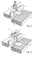
- the lift 1 shown in figs. 1-5 and fig. 11 is intended for a passenger vehicle 2, in this case a train car, that has a doorway 3. Through the doorway 3 passengers shall pass quickly at alighting or entering often carrying bulky luggage.
- the lift 1 is placed on board the vehicle 2 in the doorway 3 and has a lift platform 4, which in a parking position is vertically raised and rotated away from the doorway 3. In this position it forms no obstacles whatsoever for alighting or entering despite the fact that the doorway 3 shown in this example is a very narrow one.
- the lift platform 4 With the aid of a lying down U-shaped swivel arm 5 can rotate about a first vertical axis V1 and a second vertical axis V2 in a parallel displacement motion from inside of the vehicle 2, through the doorway 3 and to the outside of the vehicle 2. Said parallel displacement motion is achieved the with the aid of a two row chain 6, that is shown only in fig 11 .
- the second sprocket 8 is also rotated and thus the lift platform 4 (c.f. figs. 4-5 ).
- the actuators 10, 11 are preferably electric and suitably they are disconnectable or crankable by hand in order keep up an emergency function in case there is a power failure.
- the swivel arm 5 carries with the aid of the other vertical axis V2 in a rotatable way a lift mast 13, which on its part with the aid of a horizontal axis H carries the lift platform 4. Due to the horizontal axis H, the lift platform 4 is able to when it is located in the position shown in fig. 3 to be folded down to a horizontal position of use, as illustrated in fig. 4 . In this position it is possible to safely embark on and or leave the lift platform 4 through the doorway 3 of the vehicle 2.
- the lift mast 13 is vertical and is height adjustable, so that the lift platform 4 connected thereto can be lifted and lowered as needed.
- One of the thoughts behind the invention is that the lift platform 4 when being lifted or lowered concurrently is rotated to and from the doorway 3 in order blocked it as little as possible for passengers, who have no need of the lift. Therefore, in an entirely lowered position or ground position the lift platform 4 occupies preferably the position shown in fig. 5 , in which the passage into and out of the doorway 3 and the ground area 14 straight outside of the doorway is more or less uninfluenced by the lift 1. For a user of the lift 1 this is advantageous too, since alighting or entering can be performed without any stress through other passengers.
- the lift 1 according to the second embodiment includes a lifting parallelogram 15, that is well-known in the art and is turned towards the doorway 3.
- the lifting parallelogram 15 has an outer, especially telescopic arm end 16, of which a detailed view is shown in fig. 12 .
- a swivel head 17 is shown rotatably mounted on the arm end 16.
- the two are adjoined by means of a joint 18, that defines the second vertical axis V2 of the lift.
- the joint 18 is lockable with the aid of a cylinder pin 19, which in defined angle positions is insertable in control orifices 20, 21 in either part.
- the cylinder pin 19 is operatable with a pistol grip 22, that has a releasable safety latch 23.
- the horizontal axis H located at the bottom of the swivel head 17 and includes a pivot 24, which on said head 17 rotatably carries an elongated mount 25 for the lift platform 4. As shown the mount 25 is down foldable to a horizontal position, in which it is locked by an abutment projection 26. In a raised position the mount 25 defines the first vertical axis V1 of the lift 1, i.e. the axis about which the lift platform 4 is rotated as described above when rotating from the parking position to the position in or outside of the doorway 3.
- the above lifting parallelogram 15 includes several arms that interact with each other by means of horizontal joints L1, L2, L3, etc., which in a way known ensure that the lift platform 4 in a position of use is kept in balance, i.e. horizontal.
- the swivel head 17 described above in detail is affixed. This allows it to rotate from the parking position shown in fig. 1 about the first vertical axis V1 to the position shown in fig. 2 , in which the lift platform 4 is vertically raised in the middle of the doorway 3. From the position shown in fig. 2 the lift platform 4 is folded down about the horizontal axis H to the position of use shown in fig. 3 .
- the lift platform 4 is rotated about the second vertical axis V2 and is lowered with the aid of lifting parallelogram 15 down to the ground outside of the vehicle 2 on a spot, which, as is illustrated in fig. 10 , is located aside of the area 14 straight outside of the doorway 3.
- the lift 1 according to the second embodiment thus also meets all the requirements to be fulfilled according to the invention and does also give the desired advantages compared to prior art.
- the lift 1 according to the first embodiment constitutes an all motorized solution, while the second one constitutes a manual solution except for the lifting parallelogram 15, that is run hydraulically. It is however obvious that it is very well possible to add or take away different motor solutions. Moreover it has to be said that the lift 1 according to the first embodiment with the U-shaped curved swivel arm is intended especially for narrow doorways 3, while the one according to the second embodiment works best in connection with somewhat broader doorways 3, since the lifting parallelogram 15 requires a little more space.
Landscapes
- Health & Medical Sciences (AREA)
- Public Health (AREA)
- Engineering & Computer Science (AREA)
- Life Sciences & Earth Sciences (AREA)
- Animal Behavior & Ethology (AREA)
- General Health & Medical Sciences (AREA)
- Veterinary Medicine (AREA)
- Transportation (AREA)
- Mechanical Engineering (AREA)
- Vehicle Step Arrangements And Article Storage (AREA)
Applications Claiming Priority (1)
| Application Number | Priority Date | Filing Date | Title |
|---|---|---|---|
| SE0802015 | 2008-09-22 |
Publications (2)
| Publication Number | Publication Date |
|---|---|
| EP2165690A2 true EP2165690A2 (de) | 2010-03-24 |
| EP2165690A3 EP2165690A3 (de) | 2011-05-04 |
Family
ID=41416258
Family Applications (1)
| Application Number | Title | Priority Date | Filing Date |
|---|---|---|---|
| EP09170944A Withdrawn EP2165690A3 (de) | 2008-09-22 | 2009-09-22 | Hebevorrichtung für Personenkraftwagen |
Country Status (1)
| Country | Link |
|---|---|
| EP (1) | EP2165690A3 (de) |
Cited By (3)
| Publication number | Priority date | Publication date | Assignee | Title |
|---|---|---|---|---|
| ITTO20130414A1 (it) * | 2013-05-23 | 2014-11-24 | Tekontracks S R L | Dispositivo sollevatore per carrozze ferroviarie, utilizzabile per la salita e la discesa di persone su sedia a rotelle e carrozzine per bambini |
| ITTO20130412A1 (it) * | 2013-05-23 | 2014-11-24 | Tekontracks S R L | Dispositivo sollevatore per carrozze ferroviarie, utilizzabile per la salita e la discesa di persone su sedia a rotelle e carrozzine per bambini |
| EP3476378A1 (de) * | 2017-10-30 | 2019-05-01 | Orthotec AG | Schwenklift |
Citations (1)
| Publication number | Priority date | Publication date | Assignee | Title |
|---|---|---|---|---|
| US5180275A (en) | 1991-05-28 | 1993-01-19 | The Braun Corporation | Rotary bus lift with power stowable platform |
Family Cites Families (6)
| Publication number | Priority date | Publication date | Assignee | Title |
|---|---|---|---|---|
| DE2928607A1 (de) * | 1979-07-14 | 1981-02-19 | Bernhard Bruns Maschf | Um eine lotrechte achse schwenkbare, heb- und senkbare hubplattform zum be- und entladen eines lastkraftwagens |
| FR2594389A1 (fr) * | 1986-02-14 | 1987-08-21 | Bourgeois Jacques | Dispositif de chargement dans un vehicule, en particulier pour fauteuils roulants de handicapes |
| US5542811A (en) * | 1995-01-04 | 1996-08-06 | Vartanian; Roger | Wheelchair lift with laterally displaceable support post for vertical and rotational displacement |
| WO2003104133A2 (en) * | 2002-06-06 | 2003-12-18 | Ricon Corporation | Single arm wheelchair lift |
| FR2878433A1 (fr) * | 2004-11-26 | 2006-06-02 | Alain Bourgeois | Dispositif de transfert et de chargement de fauteuil roulant a bord d'un vehicule |
| FR2918559B1 (fr) * | 2007-07-13 | 2009-09-11 | Alain Bourgeois | Dispositif elevateur pour fauteuil roulant |
-
2009
- 2009-09-22 EP EP09170944A patent/EP2165690A3/de not_active Withdrawn
Patent Citations (1)
| Publication number | Priority date | Publication date | Assignee | Title |
|---|---|---|---|---|
| US5180275A (en) | 1991-05-28 | 1993-01-19 | The Braun Corporation | Rotary bus lift with power stowable platform |
Cited By (3)
| Publication number | Priority date | Publication date | Assignee | Title |
|---|---|---|---|---|
| ITTO20130414A1 (it) * | 2013-05-23 | 2014-11-24 | Tekontracks S R L | Dispositivo sollevatore per carrozze ferroviarie, utilizzabile per la salita e la discesa di persone su sedia a rotelle e carrozzine per bambini |
| ITTO20130412A1 (it) * | 2013-05-23 | 2014-11-24 | Tekontracks S R L | Dispositivo sollevatore per carrozze ferroviarie, utilizzabile per la salita e la discesa di persone su sedia a rotelle e carrozzine per bambini |
| EP3476378A1 (de) * | 2017-10-30 | 2019-05-01 | Orthotec AG | Schwenklift |
Also Published As
| Publication number | Publication date |
|---|---|
| EP2165690A3 (de) | 2011-05-04 |
Similar Documents
| Publication | Publication Date | Title |
|---|---|---|
| US5110252A (en) | Wheelchair lift for transit vehicles having elevated passenger compartment floor | |
| KR101605203B1 (ko) | 해치 커버의 승강과 수평 이동을 전동 윈치에 의해 일련으로 구동하는 해치 커버 개폐 장치 | |
| US5542811A (en) | Wheelchair lift with laterally displaceable support post for vertical and rotational displacement | |
| US7326024B2 (en) | Wheelchair lift assembly having a compact stowed profile | |
| US5180275A (en) | Rotary bus lift with power stowable platform | |
| EP0915778B1 (de) | Unter dem boden verstaubare hebeanlage für einen rollstuhl | |
| US6860701B2 (en) | Wheelchair ramp with side barriers | |
| US11963913B2 (en) | Foldable ramp for wheelchair access to a passenger car rear door | |
| CN104245471B (zh) | 台阶装置及具备该台阶装置的铁道车辆 | |
| EP2165690A2 (de) | Hebevorrichtung für Personenkraftwagen | |
| EP2260817A2 (de) | Verdeckbare Rampe für Zugang zu öffentlichen Verkehrsmitteln | |
| GB2369344A (en) | Wheelchair access ramp for a vehicle | |
| PT2212201E (pt) | Veículo elevável | |
| WO2009140714A9 (en) | Vehicle mounted, wheelchair boarding apparatus | |
| CN113202401A (zh) | 一种站台平移伸缩门 | |
| EP1090619A2 (de) | Rampenvorrichtung | |
| CN112674976A (zh) | 一种呼吸内科检查用可调整姿势的升降平台 | |
| US20180265140A1 (en) | Gate Lift | |
| CN221691672U (zh) | 车载升降机 | |
| AU2010202803B2 (en) | Accommodation Unit | |
| RU2236966C2 (ru) | Крытый вагон для перевозки автомобилей | |
| RU2777010C1 (ru) | Подножка транспортного средства | |
| CN218228991U (zh) | 逃生门装置和轨道车辆 | |
| KR102683148B1 (ko) | 철도차량용 플러그 인/아웃 도어 시스템 | |
| JP2007270555A (ja) | 可動デッキ |
Legal Events
| Date | Code | Title | Description |
|---|---|---|---|
| PUAI | Public reference made under article 153(3) epc to a published international application that has entered the european phase |
Free format text: ORIGINAL CODE: 0009012 |
|
| AK | Designated contracting states |
Kind code of ref document: A2 Designated state(s): AT BE BG CH CY CZ DE DK EE ES FI FR GB GR HR HU IE IS IT LI LT LU LV MC MK MT NL NO PL PT RO SE SI SK SM TR |
|
| AX | Request for extension of the european patent |
Extension state: AL BA RS |
|
| RAP1 | Party data changed (applicant data changed or rights of an application transferred) |
Owner name: U-LIFT AB |
|
| PUAL | Search report despatched |
Free format text: ORIGINAL CODE: 0009013 |
|
| AK | Designated contracting states |
Kind code of ref document: A3 Designated state(s): AT BE BG CH CY CZ DE DK EE ES FI FR GB GR HR HU IE IS IT LI LT LU LV MC MK MT NL NO PL PT RO SE SI SK SM TR |
|
| AX | Request for extension of the european patent |
Extension state: AL BA RS |
|
| STAA | Information on the status of an ep patent application or granted ep patent |
Free format text: STATUS: THE APPLICATION IS DEEMED TO BE WITHDRAWN |
|
| 18D | Application deemed to be withdrawn |
Effective date: 20111105 |