EP2165551B1 - Technique for handling radio link failure in a communication network - Google Patents
Technique for handling radio link failure in a communication network Download PDFInfo
- Publication number
- EP2165551B1 EP2165551B1 EP07857011A EP07857011A EP2165551B1 EP 2165551 B1 EP2165551 B1 EP 2165551B1 EP 07857011 A EP07857011 A EP 07857011A EP 07857011 A EP07857011 A EP 07857011A EP 2165551 B1 EP2165551 B1 EP 2165551B1
- Authority
- EP
- European Patent Office
- Prior art keywords
- radio link
- link failure
- user equipment
- cell
- base station
- Prior art date
- Legal status (The legal status is an assumption and is not a legal conclusion. Google has not performed a legal analysis and makes no representation as to the accuracy of the status listed.)
- Not-in-force
Links
Images

Classifications
-
- H—ELECTRICITY
- H04—ELECTRIC COMMUNICATION TECHNIQUE
- H04W—WIRELESS COMMUNICATION NETWORKS
- H04W76/00—Connection management
- H04W76/10—Connection setup
- H04W76/19—Connection re-establishment
-
- H—ELECTRICITY
- H04—ELECTRIC COMMUNICATION TECHNIQUE
- H04W—WIRELESS COMMUNICATION NETWORKS
- H04W24/00—Supervisory, monitoring or testing arrangements
- H04W24/04—Arrangements for maintaining operational condition
-
- H—ELECTRICITY
- H04—ELECTRIC COMMUNICATION TECHNIQUE
- H04W—WIRELESS COMMUNICATION NETWORKS
- H04W76/00—Connection management
- H04W76/10—Connection setup
- H04W76/11—Allocation or use of connection identifiers
Definitions
- the invention generally relates to the field of handling radio link failure in a communication network.
- Radio link failure happens in a mobile communication network when a mobile station, e.g. a mobile telephone, loses connection with the communication network in an uncontrolled manner. Radio link failures usually do not occur randomly. Typically, radio link failures occur at certain locations, or when a mobile station is moving out of the network coverage area of cell and into the network coverage area of another cell that has not been configured correctly. A reason for a connection loss may for example be that the mobile station is rapidly leaving the radio coverage area of the base station which is serving the mobile station. In such a situation, if RLF cannot be avoided, it is desired that the mobile station as soon as possible reconnects to the communication network in order to minimize the interruption time, a loss of transmission data and the perceived service degradation for the user of the mobile station. For this purpose, after losing connection with the communication network, the mobile station performs a plurality of network reconnection procedures including selecting a new base station and cell and accessing the new base station in order to reconnect to the communication network.
- next generation mobile networks (NGMN) according to the Long Term Evolution (LTE) of the 3GPP (Third Generation Partnership Project) radio technology
- LTE_IDLE state in LTE is a power conversation state for the UE. In this state, the UE is not transmitting or receiving data packets to or from the network.
- eNodeB evolved Node B
- the eNodeB has no information regarding the UE which is requesting to reconnect available.
- EPC evolved packet core
- context information regarding the UE has to be obtained by the eNodeB via the EPC.
- EPC is the mobile packet backbone network behind the eNodeBs.
- a state transition from LTE_IDLE state to LTE_IDLE active state, i.e. the state in which the UE is registered with the communication network and a Radio Resource Control (RRC) connection with the eNodeB is established, will take approximately 100 ms.
- RRC Radio Resource Control
- Document EP 1 720 367 A1 concerns a method of operating a user equipment. If a problem, such as loss of coverage or call has occurred, information about the location where the problem has occurred is stored in the memory of the user equipment. After successful recovery from the problem, an alternative base station is also stored in the memory. Next time the same problem is encountered at the same location, the user equipment uses the previous information for alleviating the problem or performing a fast recovery.
- the method comprises the steps of detecting a radio link failure with respect to a user equipment and logging an identifier of the user equipment effected by the radio link failure together with at least one of the data items of a time stamp of when the radio link failure was detected and a reference to a cell which was serving the user equipment before the radio link failure was detected.
- user equipment context information may be sent to a base station which is serving a cell, to which user equipments are frequently reconnecting after a radio link failure has occurred.
- Frequently reconnecting means for example that a user equipment is reconnecting more than a predetermined number of times (or a predetermined percentage) in a predetermined time period to the cell after a radio link failure has occurred.
- the base station, to which the user equipment context information is sent may also be determined by a network operator.
- handover parameters between cells having a high amount of radio link failures and cells, to which user equipments are frequently reconnecting after a radio link failure has occurred may be adjusted. Since it is known that connection losses and reconnections in certain neighbouring cells occur frequently, network parameters may be adjusted in that the time for handovers between cells having a high amount of radio link failures and cells, to which user equipments are frequently reconnecting after a radio link failure has occurred, may be optimized.
- the handover parameters may for example include intra-frequency handover parameters. By adjusting the handover parameters, the number of dropped calls may even be reduced.
- an X2 interface between base station serving cells having a high amount of radio link failures and cells, to which user equipments are frequently reconnected after a radio link failure has occurred may be defined.
- the X2 interface may in particular support handovers of user equipments between base stations in LT_ACTIVE state.
- the deployment of a base station may be adjusted so that a cell having a high amount of radio link failures and a cell, to which user equipments are frequently reconnected after a radio link failure has occurred, are served by the same base station.
- the time for reconnection after the occurrence of a radio link failure may be reduced, since the base station has all necessary user equipment context information available and does not have to request it when a reconnection request arrives.
- the method may be executed by a base station, such as an eNodeB or any other suitable network component.
- this method may be executed by the base station to which the user equipment is connected when the radio link failure occurs.
- the user equipment may be any kind of communication terminal, e.g. a mobile telephone which is capable of communicating within the communication network.
- the method further comprises the steps of maintaining radio link failure information including an identifier of a user equipment effected by the radio link failure together with at least one of the data items of a time stamp of when the radio link failure was detected and a reference to a cell which was serving the user equipment before the radio link failure was detected, receiving reconnection information including an identifier of a reconnected user equipment effected by a radio link failure after the user equipment is reconnected to the communication network and correlating the radio link failure information with the reconnection information to obtain a correlation result.
- the correlation result may for example be a relation between cells having a high amount of radio link failures and cells to which mobile terminals are frequently reconnecting after a radio link failure has occurred.
- This method may be executed by a base station, such as an eNodeB or any other suitable network component.
- this method may be executed by a base station, to which a user equipment is reconnected after a radio link failure has occurred.
- this base station may be the same base station to which the user equipment was connected before the radio link failure has occurred.
- the method may also be executed by a network component which is not a base station, e.g. a core network component. In this case, this network component receives the radio link failure information and the reconnection information from the base station(s) to which the user equipment was connected before the radio link failure and to which the user equipment is reconnected after the radio link failure.
- the identifier may be any kind of identification information which unambiguously identifies the user equipment, e.g. a Radio Network Temporary Identity (RNTI) such as a Cell RNTI (C-RNTI), a Random Access RNTI (RA-RNTI), a Paging RNTI or a BCCH RNTI, a Temporary Mobile Subscriber Identity (TMSI) such as a Packet TMSI (P-TMSI) or a S-TMSI, or a Globally Unique Temporary Identity (GUTI).
- RNTI Radio Network Temporary Identity
- C-RNTI Cell RNTI
- RA-RNTI Random Access RNTI
- Paging RNTI Paging RNTI
- BCCH RNTI a Temporary Mobile Subscriber Identity
- TMSI Temporary Mobile Subscriber Identity
- P-TMSI Packet TMSI
- S-TMSI S-TMSI
- GUI Globally Unique Temporary Identity
- the radio link failure information For correlating the radio link failure information with the reconnection information in order to obtain a correlation result, in many cases only the identifier of the user equipment and a time stamp of when the radio link failure was detected or a reference to a cell which was serving the user equipment before the radio link failure was detected are necessary. In other words, it may be sufficient that only the identifier of a user equipment effected by the radio link failure together with a time stamp of when the radio link failure was detected or the identifier of a user equipment effected by the radio link failure together with a reference to a cell which was serving user equipment before the radio link failure was detected are maintained.
- the cell reference may for example not be necessary in situations in which time stamps from different base stations of when radio link failures were detected can be correlated.
- both the time stamp and the cell information may be maintained together with the identifier.
- the reconnection information may further include at least one of a time stamp of when the user equipment was reconnected with the communication network and a reference to a cell which is serving the user equipment after reconnection to the communication network. Similar to the maintenance of the radio link failure information, only one of a time stamp of when the user equipment was reconnected with the communication network and a reference to a cell which is serving the user equipment after reconnection to the communication network may be received together with the identifier of the reconnected user equipment. Receiving both the time stamp and the cell information may facilitate a correlation of the radio link failure information with the reconnection information in order to obtain a correlation result.
- the correlation result may be evaluated and based on the evaluation, cells having a high amount of radio link failures may be determined.
- cells having a high amount of radio link failures may be determined.
- it may be determined, in which cells of a communication network more radio link failures than in other cells of the communication network occur.
- the result of this determination may be expressed in absolute numbers or as a percentage.
- the correlation result may be evaluated and based on the evaluation, cells, to which user equipments are frequently reconnecting after radio link failures have occurred, may be determined.
- cells to which user equipments are frequently reconnecting after radio link failures have occurred.
- the user equipment context information may comprise data which the base station requires for communicating with user equipment.
- Such user equipment context information may for example be the identifier of the user equipment (e.g. for looking up further information by the base station itself, security keying material, a Radio Resource Control (RRC) context, a System Architecture Evolution (SAE) bearer context or a S1 interface context reference.
- RRC Radio Resource Control
- SAE System Architecture Evolution
- the sending of user equipment context information to a base station which is serving a cell, to which user equipments are frequently reconnecting after a radio link failure has occurred may take place every time the user equipment is served by a cell having a high amount of radio link failure.
- a security measure in the cell, to which user equipments are frequently reconnecting after a radio link failure has occurred is provided, since the base station already has the user equipment context information available and does not have to request it after the user equipment requests network reconnection.
- the network reconnection time after the occurrence of an radio link failure can be reduced.
- the sending of the user equipment context information to a base station which is serving a cell, to which user equipments are frequently reconnecting after a radio link failure has occurred may also take place after a radio link failure of the user equipment has been detected.
- the time period between the detection of the radio link failure and the reconnection to the communication network may be used for providing the cell, to which user equipments are frequently reconnecting after a RLF has occurred, with the potentially required user equipment context information.
- an interface between base stations may be set up. Thereby, the time for handover between different base stations may be reduced.
- Related cells may also be defined as neighbour cells in order to facilitate future handover attempts.
- Such related cells may for example be cells, in which radio link failures are frequently occurring and cells, to which user equipments are frequently reconnecting after a radio link failure has occurred.
- the future handover attempt may be performed via the evolved packet core.
- the invention can be practiced in the form of hardware, in the form of software and in the form of a combined hardware/software approach.
- a computer program product according to the subject-matter of independent claim 13 is provided.
- the computer program product comprises program code portions for performing one or more of the steps of the methods described above when the computer program product is run on one or more components of a network.
- the computer program product may be stored on a computer-readable recording medium.
- a base station according to the subject-matter of independent claim 15 is provided.
- the base station comprises a detecting unit for detecting a radio link failure with respect to a user equipment, a logging unit for logging identifier of the user equipment effected by the radio link failure together with at least one of the data items of a time stamp of when the radio link failure was detected and a reference to a cell which was serving the user equipment before the radio link failure was detected and a sending unit which is sending user equipment context information to a base station which is serving a cell, to which user equipments are frequently reconnecting after a radio link failure has occurred.
- the base station may in particular be an eNodeB.
- the base station comprises a maintaining unit for maintaining radio link failure information including the identifier of a user equipment effected by the radio link failure together with at least one of the data items of a time stamp of when the radio link failure was detected and a reference to a cell which was serving the user equipment before the radio link failure was detected, a receiving unit for receiving reconnection information including an identifier of a reconnected user equipment effected by a radio link failure after the user equipment is reconnected to the communication network and a correlating unit for correlating the radio link failure information with the reconnection information to obtain a correlation result.
- the network component may be an eNodeB.
- various exemplary scenarios of handling radio link failure in a communication network are disclosed. These exemplary embodiments are based on a NGMN according to LTE. However, the present invention is not limited to LTE. The present invention may as well be employed in any other communication network, e.g. a network according to the Universal Mobile Telecommunications System (UMTS) standard.
- UMTS Universal Mobile Telecommunications System
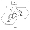
- Fig. 1 shows a schematic block diagram illustrating a communication network 10 including a first eNodeB eNB1 which is serving a first cell C1 and a second eNodeB eNB2 which is serving a second cell C2.
- the first and the second eNodeBs eNB1 and eNB2 are connected by wire or via an air interface 13, 14 with a network component 18.
- the network component 18 is further connected with a core network (not shown).
- An X2 interface 12 is provided between the first eNodeB eNB1 and the second eNodeB eNB2.
- a user equipment UE is located in the cell C1 and is in communication via an air interface 16 with the first eNodeB eNB1.
- the user of the user equipment UE is travelling in a high speed train (not shown).
- the high speed train with the UE is leaving cell C1 and is rapidly entering the network coverage area of cell C2, as indicated by arrow 15. Due to the rapid relocation, i.e. the rapid movement from cell C1 to cell C2, a radio link failure occurs. Accordingly, the UE is losing the connection over the air interface 16 with the first eNodeB eNB1.
- eNB1 After the occurrence of the radio link failure, eNB1 detects the radio link failure.
- the first eNodeB eNB1 logs an identifier of the UE together with at least one of a time stamp of when the radio link failure was detected and a reference to the cell C1 which was serving the UE before the radio link failure was detected.
- the first eNodeB eNB1 provides this logging information to the network component 18.
- the UE After the occurrence of the radio link failure, the UE is located in the network coverage area of the second eNodeB eNB2, i.e. in cell C2. Accordingly, the UE selects this cell for reconnection with the communication network 10 and tries to reconnect via an air interface 17 with the second eNodeB eNB2. The reconnection is successful.
- the second eNodeB eNB2 logs an identifier of the UE, optionally together with a time stamp of when the UE was connected to the second eNodeB eNB2 and a reference to the cell C2 which is serving the UE after reconnection to the communication network 10.
- the second eNodeB eNB2 provides this information via the connection 14 to the network component 18.
- the network component 18 has radio link failure information from the first eNodeB eNB1 and reconnection information from the second eNodeB eNB2 available.
- the network component 18 may receive corresponding information from other eNodeBs (not shown) of the communication network 10.
- the network component 18 then correlates the radio link failure information and the reconnection information to obtain correlation results. Thereafter, it evaluates each correlation result in order to determine cells having a high amount of radio link failures and cells, to which user equipment are frequently reconnecting after a RLF has occurred. Based on this information, the network parameters between certain cells, in the present embodiment between cell C1 and cell C2, may be optimized.
- the network component 18 has determined based on the correlation result that radio link failures occur frequently in cell C1 and user equipments are frequently reconnecting after the occurrence of radio link failures at cell C2 to the communication network 10.
- the network parameters between cells C1 and C2 are optimized in that any time a UE is located in cell C1, the user equipment context information of this UE is sent from the first eNodeB in eNB1 to the second eNodeB eNB2.
- the probability is high that radio link failures occur in cell C1 and the probability is as well high that after the occurrence of a radio link failure in cell C1, the UE will be reconnecting to the second eNodeB eNB2 of cell C2, the second eNodeB eNB2 has already the user equipment context information of the UE available. Therefore, reconnection of UE to the communication network 10 is accelerated, since the second eNodeB eNB2 does not have to determine or request further reconnection information, for example from the communication network 10.
- the user equipment context information is sent from the first eNodeB eNB1 to the second eNodeB eNB2 preferably before a radio link failures has occurred, the delay due to the detection of a radio link failure and a reconnection request can be avoided.
- the UE after the occurrence of a radio link failure in cell C1 again reconnects to the same eNodeB, i.e. eNB1. This may for example happen in case the first eNodeB eNB1 temporarily cannot offer any services.
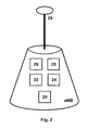
- Fig. 2 shows a schematic block diagram of an eNodeB eNB.
- the eNodeB may be used in the communication network 10 shown in Fig. 1 .
- the eNodeB comprises an antenna 29 for communicating with a plurality of user equipments.
- the eNodeB eNB comprises a detecting unit 20 for detecting a radio link failure with respect to a user equipment, a logging unit 22 for logging an identifier of the user equipment effected by the radio link failure together with at least one of a time stamp of when the radio link failure was detected and a reference to a cell which was serving the user equipment before the radio link failure was detected, a maintaining unit 24 for maintaining radio link failure information including an identifier of the user equipment effected by the radio link failure together with at least one of a time stamp of when the radio link failure was detected and a reference to a cell which was serving the user equipment before the radio link failure was detected, a receiving unit 26 for receiving reconnection information including an identifier of a reconnected user equipment effected by the radio link failure after the user equipment is reconnected to the communication network and a correlating unit 28 for correlating the radio link failure information and the reconnection information to obtain a correlation result.
- the eNodeB eNB is receiving the radio link failure information and the reconnection information and is capable of correlating this information to obtain a correlation result.
- the embodiment according to Fig. 2 deviates from the embodiment according to Fig. 1 , in that in the embodiment according to Fig. 1 , the network component 18 is the instance for correlating the radio link failure information with the reconnection information.
- the eNodeB eNB is providing this correlation. It is also possible that both the network component 18 and the eNB are providing correlation results.
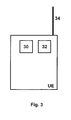
- Fig. 3 shows a schematic block diagram illustrating a user equipment UE.
- the user equipment UE comprises an antenna 34 for communicating via an air interface with a base station, e.g. an eNodeB (not shown).
- the user equipment UE comprises a sending unit 30 for sending an identifier of the user equipment UE to a base station and a detecting unit 32 for detecting a radio link failure.
- the user equipment UE sends the same identifier to the same or another base station after a radio link failure of the user equipment UE has been detected and the user equipment is reconnecting or is already reconnected to a communication network.
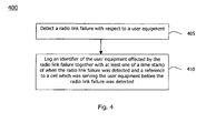
- Fig. 4 shows a flow chart 400 of a first method embodiment of the present invention.
- the method embodiment relates to handling radio link failure in a communication network and may be practiced by an eNodeB eNB1 shown in Fig. 1 , an eNodeB eNB shown in Fig. 2 or by other apparatuses.
- the method starts in step 405 by detecting a radio link failure with respect to a user equipment.
- a next step 410 an identifier of the user equipment effected by the radio link failure together with at least one of a time stamp of when the radio link failure was detected and a reference to a cell which was serving the user equipment before the radio link failure was detected is logged.
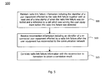
- Fig. 5 shows a flow chart 500 of a further method embodiment.
- the method embodiment relates to handling radio link failure in a communication network and may be practiced by an eNodeB eNB1 shown in Fig. 1 , an eNodeB eNB shown in Fig. 2 or by other apparatuses.
- the method starts in step 505 by maintaining radio link failure information including the identifier of a user equipment effected by a radio link failure together with at least one of a time stamp of when the radio link failure was detected and a reference to a cell which was serving the user equipment before the radio link failure was detected.
- reconnection information including an identifier of a reconnected user equipment effected by a radio link failure after the user equipment is reconnected to the communication network is received.
- the radio link failure information is correlated with the reconnection information to obtain a correlation result.
- Fig. 6 shows a flow chart 600 of a further method embodiment.
- the method embodiment relates to handling radio link failure in a communication network and may be practiced by a user equipment UE shown in Fig. 1 or Fig. 3 or by other apparatuses.
- the method starts in step 605 by sending an identifier of the user equipment to a base station.
- This sending of the identifier to the base station may occur during normal operation, i.e. during normal communication of the user equipment with the base station.
- a radio link failure is detected by the user equipment.
- the same identifier is sent to the same or another base station after a radio link failure of user equipment has been detected and the user equipment is reconnected to the communication network.
- the identifier is sent to the same base station in case the user equipment is still located in the network coverage area of this base station. However, if the user equipment has moved to the network coverage area of another base station, i.e. another cell, the user equipment sends the same identifier to this base station.
- the present technique for handling radio link failure in a communication network provides the advantage that the interruption time period after a radio link failure has occurred can be minimized. Thereby, data loss during interruption time can be minimized or avoided and a service degradation perceived by the user of a user equipment can be reduced.
- the network parameters of the communication network may be optimised in such a way that the user of a user equipment does not recognize a call drop due to radio link failure.
Landscapes
- Engineering & Computer Science (AREA)
- Computer Networks & Wireless Communication (AREA)
- Signal Processing (AREA)
- Mobile Radio Communication Systems (AREA)
- Maintenance And Management Of Digital Transmission (AREA)
- Monitoring And Testing Of Transmission In General (AREA)
- Radio Relay Systems (AREA)
Applications Claiming Priority (3)
| Application Number | Priority Date | Filing Date | Title |
|---|---|---|---|
| SE0701438 | 2007-06-13 | ||
| US97777907P | 2007-10-05 | 2007-10-05 | |
| PCT/EP2007/011288 WO2008151658A1 (en) | 2007-06-13 | 2007-12-20 | Technique for handling radio link failure in a communication network |
Publications (2)
| Publication Number | Publication Date |
|---|---|
| EP2165551A1 EP2165551A1 (en) | 2010-03-24 |
| EP2165551B1 true EP2165551B1 (en) | 2011-05-04 |
Family
ID=39357955
Family Applications (1)
| Application Number | Title | Priority Date | Filing Date |
|---|---|---|---|
| EP07857011A Not-in-force EP2165551B1 (en) | 2007-06-13 | 2007-12-20 | Technique for handling radio link failure in a communication network |
Country Status (7)
| Country | Link |
|---|---|
| US (1) | US8929202B2 (enExample) |
| EP (1) | EP2165551B1 (enExample) |
| JP (1) | JP5185997B2 (enExample) |
| AT (1) | ATE508609T1 (enExample) |
| DE (1) | DE602007014415D1 (enExample) |
| TW (1) | TWI458380B (enExample) |
| WO (1) | WO2008151658A1 (enExample) |
Families Citing this family (35)
| Publication number | Priority date | Publication date | Assignee | Title |
|---|---|---|---|---|
| WO2009086690A1 (en) * | 2008-01-04 | 2009-07-16 | Lucent Technologies Inc. | Transmission methods, network equipment, user equipment and telecommunication system |
| US8559298B2 (en) * | 2008-06-30 | 2013-10-15 | Qualcomm Incorporated | Method and apparatus for automatic handover optimization |
| GB2464137B (en) * | 2008-10-06 | 2011-06-08 | Samsung Electronics Co Ltd | Method of operating a communication system |
| DE102008058346A1 (de) * | 2008-11-20 | 2010-06-17 | T-Mobile International Ag | Verfahren zur automatischen Konfiguration von Nachbarschaftsbeziehungen in Mobilfunknetzen |
| KR101580151B1 (ko) * | 2009-03-16 | 2015-12-24 | 삼성전자주식회사 | 이동통신시스템에서 무선링크 실패로 인한 호 절단을 개선하기 위한 방법 및 시스템 |
| US9166875B2 (en) * | 2009-06-22 | 2015-10-20 | Qualcomm Incorporated | Method and apparatus for network optimization using SON solutions |
| CN101959262B (zh) * | 2009-07-15 | 2015-07-22 | 中兴通讯股份有限公司 | 切换失败指示信息的通知方法与装置 |
| CN102026165B (zh) * | 2009-09-14 | 2014-11-05 | 中兴通讯股份有限公司 | 一种用于识别终端的方法及系统 |
| EP2583494B1 (en) * | 2010-06-18 | 2019-02-06 | Nokia Solutions and Networks Oy | Correlation of collected mobile terminal based measurement data and positioning data |
| US8774207B2 (en) * | 2010-07-31 | 2014-07-08 | Motorola Solutions, Inc. | Methods for bearer reservation, maintenance, and use in a communication system |
| CN103154899A (zh) | 2010-10-04 | 2013-06-12 | 京瓷株式会社 | 移动通信方法、无线终端和基站 |
| US8838156B2 (en) | 2010-10-22 | 2014-09-16 | Motorola Solutions, Inc. | Multi-bearer rate control for transporting user plane data |
| JP5727194B2 (ja) * | 2010-10-27 | 2015-06-03 | 京セラ株式会社 | 無線通信システム及び無線通信方法 |
| US9813928B2 (en) * | 2011-11-03 | 2017-11-07 | Nokia Solutions And Networks Oy | Minimization of drive tests data and radio link failure information correlation |
| WO2013167204A1 (en) * | 2012-05-11 | 2013-11-14 | Nokia Siemens Networks Oy | Method, device and computer program for reporting radio link failures (rlf) for cellular communication based on communication links enabled on at least two different access technologies |
| KR102044019B1 (ko) | 2012-08-03 | 2019-12-02 | 삼성전자주식회사 | 이동성 매개변수 조정 방법 및 장치 |
| GB2507299B (en) * | 2012-10-25 | 2015-04-01 | Samsung Electronics Co Ltd | Mobile terminal preparation |
| US10952091B2 (en) | 2012-10-29 | 2021-03-16 | T-Mobile Usa, Inc. | Quality of user experience analysis |
| US9538409B2 (en) | 2012-10-29 | 2017-01-03 | T-Mobile Usa, Inc. | Quality of user experience analysis |
| US10412550B2 (en) | 2012-10-29 | 2019-09-10 | T-Mobile Usa, Inc. | Remote driving of mobile device diagnostic applications |
| US10237144B2 (en) | 2012-10-29 | 2019-03-19 | T-Mobile Usa, Inc. | Quality of user experience analysis |
| WO2014067049A1 (en) * | 2012-10-29 | 2014-05-08 | Empire Technology Development Llc | Mobility management for lte network for high-speed railway |
| US10313905B2 (en) | 2012-10-29 | 2019-06-04 | T-Mobile Usa, Inc. | Contextual quality of user experience analysis using equipment dynamics |
| US9237474B2 (en) | 2012-10-29 | 2016-01-12 | T-Mobile Usa, Inc. | Network device trace correlation |
| JP6219566B2 (ja) * | 2012-12-28 | 2017-10-25 | 株式会社Nttドコモ | 移動局及び移動通信方法 |
| EP2963966B1 (en) * | 2013-02-28 | 2018-03-14 | Nec Corporation | Radio link failure in a dual connectivity network |
| US10743242B2 (en) * | 2013-03-14 | 2020-08-11 | Itron Networked Solutions, Inc. | Set of optimizations applicable to a wireless networks operating in TV white space bands |
| WO2014161167A1 (zh) * | 2013-04-03 | 2014-10-09 | 富士通株式会社 | 信息处理方法、触发测量报告的方法及其装置、通信系统 |
| US9608859B2 (en) * | 2013-10-25 | 2017-03-28 | Aruba Networks, Inc. | System, apparatus and method for reducing failover time through redundancy using virtual access points |
| US10462249B2 (en) * | 2014-08-25 | 2019-10-29 | Super Micro Computer, Inc. | Globally distributed virtual cache for worldwide real-time data access |
| CN107040576B (zh) * | 2016-12-08 | 2020-03-10 | 阿里巴巴集团控股有限公司 | 信息推送方法及装置、通讯系统 |
| US10952273B2 (en) * | 2017-08-10 | 2021-03-16 | At&T Intellectual Property I, L.P. | Detecting and correcting radio link failures based on different usage scenarios |
| CN113661775B (zh) | 2019-02-12 | 2024-08-16 | 交互数字专利控股公司 | 用于侧链路无线电链路监视和确定无线电链路故障的方法 |
| US11924895B2 (en) * | 2020-02-14 | 2024-03-05 | Qualcomm Incorporated | Techniques for new radio layer two relay |
| US20240314598A1 (en) * | 2023-03-16 | 2024-09-19 | Apple Inc. | Techniques for identifying and utilizing connectivity issue patterns |
Family Cites Families (11)
| Publication number | Priority date | Publication date | Assignee | Title |
|---|---|---|---|---|
| JPH1023501A (ja) * | 1996-07-03 | 1998-01-23 | Fujitsu Ltd | 移動体端末の局間ハンドオーバ方式 |
| US6317596B1 (en) * | 1998-10-20 | 2001-11-13 | Denso Corporation | Error detecting and reporting system in a wireless communication network |
| US6459695B1 (en) * | 1999-02-22 | 2002-10-01 | Lucent Technologies Inc. | System and method for determining radio frequency coverage trouble spots in a wireless communication system |
| US7219124B2 (en) * | 2000-08-01 | 2007-05-15 | Qwest Communications International Inc. | Provisioning system and method for auto-discovering customer premises equipment in activating xDSL |
| JP3588056B2 (ja) * | 2001-03-06 | 2004-11-10 | エヌ・ティ・ティ・コムウェア株式会社 | 移動通信システムにおけるサービスエリアの通信品質維持方法、管理サーバシステム |
| US7136636B1 (en) * | 2002-05-13 | 2006-11-14 | Sprint Spectrum L.P. | System and method for use of location to monitor wireless network conditions |
| US20040077331A1 (en) * | 2002-10-17 | 2004-04-22 | King Kevin H. | System and method for tracking dropped calls in a wireless telecommunication system |
| US7065351B2 (en) * | 2003-01-30 | 2006-06-20 | Qualcomm Incorporated | Event-triggered data collection |
| ATE391402T1 (de) * | 2005-05-04 | 2008-04-15 | Ericsson Telefon Ab L M | Kompensierung für schlechte deckung |
| EP1765030A1 (en) * | 2005-09-19 | 2007-03-21 | Mitsubishi Electric Information Technology Centre Europe B.V. | Method for transferring the context of a mobile terminal in a wireless telecommunication network |
| US9118529B2 (en) * | 2006-06-20 | 2015-08-25 | Qualcomm Incorporated | Discovery of neighbor cells |
-
2007
- 2007-12-20 AT AT07857011T patent/ATE508609T1/de not_active IP Right Cessation
- 2007-12-20 WO PCT/EP2007/011288 patent/WO2008151658A1/en not_active Ceased
- 2007-12-20 EP EP07857011A patent/EP2165551B1/en not_active Not-in-force
- 2007-12-20 JP JP2010511497A patent/JP5185997B2/ja not_active Expired - Fee Related
- 2007-12-20 DE DE602007014415T patent/DE602007014415D1/de active Active
- 2007-12-20 US US12/663,964 patent/US8929202B2/en active Active
-
2008
- 2008-05-20 TW TW097118565A patent/TWI458380B/zh not_active IP Right Cessation
Also Published As
| Publication number | Publication date |
|---|---|
| US8929202B2 (en) | 2015-01-06 |
| US20100165836A1 (en) | 2010-07-01 |
| JP2010532111A (ja) | 2010-09-30 |
| JP5185997B2 (ja) | 2013-04-17 |
| TWI458380B (zh) | 2014-10-21 |
| TW200913737A (en) | 2009-03-16 |
| DE602007014415D1 (de) | 2011-06-16 |
| WO2008151658A1 (en) | 2008-12-18 |
| ATE508609T1 (de) | 2011-05-15 |
| EP2165551A1 (en) | 2010-03-24 |
Similar Documents
| Publication | Publication Date | Title |
|---|---|---|
| EP2165551B1 (en) | Technique for handling radio link failure in a communication network | |
| US12238802B2 (en) | Managing MCG fast recovery | |
| CN101483898B (zh) | 一种加快rrc连接建立的方法及装置 | |
| EP2462776B1 (en) | Operation in case of radio link failure | |
| US6400952B2 (en) | Method and apparatus for idle handoff in a cellular system | |
| US9668177B2 (en) | Handover method and apparatus in a wireless communications network | |
| KR101037342B1 (ko) | 랜덤 액세스 절차 실패 처리 방법 및 관련 통신 기기 | |
| US9445310B2 (en) | Mobile communication system, network device, and mobile communication method | |
| US20130165077A1 (en) | Method and apparatus for identifying fake networks | |
| CA2567108A1 (en) | System and method for optimizing handover in mobile communication system | |
| CN101616408A (zh) | 密钥衍生方法、设备及系统 | |
| CN101489273A (zh) | 无线链路失败恢复方法及系统 | |
| EP3827640A1 (en) | Fast mcg failure recovery with secondary node change | |
| CN106255160A (zh) | 重建rrc连接的方法和装置 | |
| CN101489274B (zh) | 无线链路恢复方法及系统 | |
| AU2014307257A1 (en) | Method for processing radio link failure in multiple base station connectivity based radio communication system, and apparatus for same | |
| CN113038551B (zh) | 一种辅小区组失败SCG Failure处理方法及装置 | |
| KR100860668B1 (ko) | 이동통신 시스템에서 통화 절단 방지 장치 및 방법 | |
| CN101594610A (zh) | 跟踪会话同步方法和装置 | |
| US20120176963A1 (en) | Voice and data connection control in a mobile device | |
| US20150119030A1 (en) | Method and apparatus for detecting cell identity conflict | |
| CN104080137B (zh) | 小区切换的方法和用户设备 | |
| CN112889306A (zh) | 用于网络接入管理的网络实体和基站 | |
| US9144101B2 (en) | Apparatus and method for wireless device connectivity upon radio link failure | |
| CN102413446B (zh) | 一种rnc间传输辅服务小区信息的方法及系统 |
Legal Events
| Date | Code | Title | Description |
|---|---|---|---|
| PUAI | Public reference made under article 153(3) epc to a published international application that has entered the european phase |
Free format text: ORIGINAL CODE: 0009012 |
|
| 17P | Request for examination filed |
Effective date: 20091218 |
|
| AK | Designated contracting states |
Kind code of ref document: A1 Designated state(s): AT BE BG CH CY CZ DE DK EE ES FI FR GB GR HU IE IS IT LI LT LU LV MC MT NL PL PT RO SE SI SK TR |
|
| AX | Request for extension of the european patent |
Extension state: AL BA HR MK RS |
|
| 17Q | First examination report despatched |
Effective date: 20100426 |
|
| DAX | Request for extension of the european patent (deleted) | ||
| RIC1 | Information provided on ipc code assigned before grant |
Ipc: H04W 76/02 20090101AFI20100826BHEP |
|
| GRAP | Despatch of communication of intention to grant a patent |
Free format text: ORIGINAL CODE: EPIDOSNIGR1 |
|
| GRAS | Grant fee paid |
Free format text: ORIGINAL CODE: EPIDOSNIGR3 |
|
| GRAA | (expected) grant |
Free format text: ORIGINAL CODE: 0009210 |
|
| AK | Designated contracting states |
Kind code of ref document: B1 Designated state(s): AT BE BG CH CY CZ DE DK EE ES FI FR GB GR HU IE IS IT LI LT LU LV MC MT NL PL PT RO SE SI SK TR |
|
| REG | Reference to a national code |
Ref country code: GB Ref legal event code: FG4D |
|
| REG | Reference to a national code |
Ref country code: CH Ref legal event code: EP |
|
| REG | Reference to a national code |
Ref country code: IE Ref legal event code: FG4D |
|
| REF | Corresponds to: |
Ref document number: 602007014415 Country of ref document: DE Date of ref document: 20110616 Kind code of ref document: P |
|
| REG | Reference to a national code |
Ref country code: DE Ref legal event code: R096 Ref document number: 602007014415 Country of ref document: DE Effective date: 20110616 |
|
| REG | Reference to a national code |
Ref country code: NL Ref legal event code: VDEP Effective date: 20110504 |
|
| PG25 | Lapsed in a contracting state [announced via postgrant information from national office to epo] |
Ref country code: PT Free format text: LAPSE BECAUSE OF FAILURE TO SUBMIT A TRANSLATION OF THE DESCRIPTION OR TO PAY THE FEE WITHIN THE PRESCRIBED TIME-LIMIT Effective date: 20110905 Ref country code: LT Free format text: LAPSE BECAUSE OF FAILURE TO SUBMIT A TRANSLATION OF THE DESCRIPTION OR TO PAY THE FEE WITHIN THE PRESCRIBED TIME-LIMIT Effective date: 20110504 Ref country code: SE Free format text: LAPSE BECAUSE OF FAILURE TO SUBMIT A TRANSLATION OF THE DESCRIPTION OR TO PAY THE FEE WITHIN THE PRESCRIBED TIME-LIMIT Effective date: 20110504 |
|
| PG25 | Lapsed in a contracting state [announced via postgrant information from national office to epo] |
Ref country code: FI Free format text: LAPSE BECAUSE OF FAILURE TO SUBMIT A TRANSLATION OF THE DESCRIPTION OR TO PAY THE FEE WITHIN THE PRESCRIBED TIME-LIMIT Effective date: 20110504 Ref country code: SI Free format text: LAPSE BECAUSE OF FAILURE TO SUBMIT A TRANSLATION OF THE DESCRIPTION OR TO PAY THE FEE WITHIN THE PRESCRIBED TIME-LIMIT Effective date: 20110504 Ref country code: BE Free format text: LAPSE BECAUSE OF FAILURE TO SUBMIT A TRANSLATION OF THE DESCRIPTION OR TO PAY THE FEE WITHIN THE PRESCRIBED TIME-LIMIT Effective date: 20110504 Ref country code: LV Free format text: LAPSE BECAUSE OF FAILURE TO SUBMIT A TRANSLATION OF THE DESCRIPTION OR TO PAY THE FEE WITHIN THE PRESCRIBED TIME-LIMIT Effective date: 20110504 Ref country code: CY Free format text: LAPSE BECAUSE OF FAILURE TO SUBMIT A TRANSLATION OF THE DESCRIPTION OR TO PAY THE FEE WITHIN THE PRESCRIBED TIME-LIMIT Effective date: 20110504 Ref country code: IS Free format text: LAPSE BECAUSE OF FAILURE TO SUBMIT A TRANSLATION OF THE DESCRIPTION OR TO PAY THE FEE WITHIN THE PRESCRIBED TIME-LIMIT Effective date: 20110904 Ref country code: AT Free format text: LAPSE BECAUSE OF FAILURE TO SUBMIT A TRANSLATION OF THE DESCRIPTION OR TO PAY THE FEE WITHIN THE PRESCRIBED TIME-LIMIT Effective date: 20110504 Ref country code: ES Free format text: LAPSE BECAUSE OF FAILURE TO SUBMIT A TRANSLATION OF THE DESCRIPTION OR TO PAY THE FEE WITHIN THE PRESCRIBED TIME-LIMIT Effective date: 20110815 Ref country code: GR Free format text: LAPSE BECAUSE OF FAILURE TO SUBMIT A TRANSLATION OF THE DESCRIPTION OR TO PAY THE FEE WITHIN THE PRESCRIBED TIME-LIMIT Effective date: 20110805 |
|
| PG25 | Lapsed in a contracting state [announced via postgrant information from national office to epo] |
Ref country code: NL Free format text: LAPSE BECAUSE OF FAILURE TO SUBMIT A TRANSLATION OF THE DESCRIPTION OR TO PAY THE FEE WITHIN THE PRESCRIBED TIME-LIMIT Effective date: 20110504 |
|
| PG25 | Lapsed in a contracting state [announced via postgrant information from national office to epo] |
Ref country code: EE Free format text: LAPSE BECAUSE OF FAILURE TO SUBMIT A TRANSLATION OF THE DESCRIPTION OR TO PAY THE FEE WITHIN THE PRESCRIBED TIME-LIMIT Effective date: 20110504 Ref country code: CZ Free format text: LAPSE BECAUSE OF FAILURE TO SUBMIT A TRANSLATION OF THE DESCRIPTION OR TO PAY THE FEE WITHIN THE PRESCRIBED TIME-LIMIT Effective date: 20110504 |
|
| PG25 | Lapsed in a contracting state [announced via postgrant information from national office to epo] |
Ref country code: PL Free format text: LAPSE BECAUSE OF FAILURE TO SUBMIT A TRANSLATION OF THE DESCRIPTION OR TO PAY THE FEE WITHIN THE PRESCRIBED TIME-LIMIT Effective date: 20110504 Ref country code: SK Free format text: LAPSE BECAUSE OF FAILURE TO SUBMIT A TRANSLATION OF THE DESCRIPTION OR TO PAY THE FEE WITHIN THE PRESCRIBED TIME-LIMIT Effective date: 20110504 Ref country code: RO Free format text: LAPSE BECAUSE OF FAILURE TO SUBMIT A TRANSLATION OF THE DESCRIPTION OR TO PAY THE FEE WITHIN THE PRESCRIBED TIME-LIMIT Effective date: 20110504 Ref country code: DK Free format text: LAPSE BECAUSE OF FAILURE TO SUBMIT A TRANSLATION OF THE DESCRIPTION OR TO PAY THE FEE WITHIN THE PRESCRIBED TIME-LIMIT Effective date: 20110504 |
|
| PLBE | No opposition filed within time limit |
Free format text: ORIGINAL CODE: 0009261 |
|
| STAA | Information on the status of an ep patent application or granted ep patent |
Free format text: STATUS: NO OPPOSITION FILED WITHIN TIME LIMIT |
|
| 26N | No opposition filed |
Effective date: 20120207 |
|
| REG | Reference to a national code |
Ref country code: DE Ref legal event code: R097 Ref document number: 602007014415 Country of ref document: DE Effective date: 20120207 |
|
| PG25 | Lapsed in a contracting state [announced via postgrant information from national office to epo] |
Ref country code: MC Free format text: LAPSE BECAUSE OF NON-PAYMENT OF DUE FEES Effective date: 20111231 |
|
| REG | Reference to a national code |
Ref country code: CH Ref legal event code: PL |
|
| REG | Reference to a national code |
Ref country code: FR Ref legal event code: ST Effective date: 20120831 |
|
| REG | Reference to a national code |
Ref country code: IE Ref legal event code: MM4A |
|
| PG25 | Lapsed in a contracting state [announced via postgrant information from national office to epo] |
Ref country code: CH Free format text: LAPSE BECAUSE OF NON-PAYMENT OF DUE FEES Effective date: 20111231 Ref country code: IE Free format text: LAPSE BECAUSE OF NON-PAYMENT OF DUE FEES Effective date: 20111220 Ref country code: LI Free format text: LAPSE BECAUSE OF NON-PAYMENT OF DUE FEES Effective date: 20111231 |
|
| PG25 | Lapsed in a contracting state [announced via postgrant information from national office to epo] |
Ref country code: MT Free format text: LAPSE BECAUSE OF FAILURE TO SUBMIT A TRANSLATION OF THE DESCRIPTION OR TO PAY THE FEE WITHIN THE PRESCRIBED TIME-LIMIT Effective date: 20110504 |
|
| PG25 | Lapsed in a contracting state [announced via postgrant information from national office to epo] |
Ref country code: FR Free format text: LAPSE BECAUSE OF NON-PAYMENT OF DUE FEES Effective date: 20120102 |
|
| PG25 | Lapsed in a contracting state [announced via postgrant information from national office to epo] |
Ref country code: LU Free format text: LAPSE BECAUSE OF NON-PAYMENT OF DUE FEES Effective date: 20111220 |
|
| PG25 | Lapsed in a contracting state [announced via postgrant information from national office to epo] |
Ref country code: BG Free format text: LAPSE BECAUSE OF FAILURE TO SUBMIT A TRANSLATION OF THE DESCRIPTION OR TO PAY THE FEE WITHIN THE PRESCRIBED TIME-LIMIT Effective date: 20110804 |
|
| PG25 | Lapsed in a contracting state [announced via postgrant information from national office to epo] |
Ref country code: TR Free format text: LAPSE BECAUSE OF FAILURE TO SUBMIT A TRANSLATION OF THE DESCRIPTION OR TO PAY THE FEE WITHIN THE PRESCRIBED TIME-LIMIT Effective date: 20110504 |
|
| PG25 | Lapsed in a contracting state [announced via postgrant information from national office to epo] |
Ref country code: HU Free format text: LAPSE BECAUSE OF FAILURE TO SUBMIT A TRANSLATION OF THE DESCRIPTION OR TO PAY THE FEE WITHIN THE PRESCRIBED TIME-LIMIT Effective date: 20110504 |
|
| PG25 | Lapsed in a contracting state [announced via postgrant information from national office to epo] |
Ref country code: IT Free format text: LAPSE BECAUSE OF NON-PAYMENT OF DUE FEES Effective date: 20151220 |
|
| PG25 | Lapsed in a contracting state [announced via postgrant information from national office to epo] |
Ref country code: IT Free format text: LAPSE BECAUSE OF NON-PAYMENT OF DUE FEES Effective date: 20151220 |
|
| PGRI | Patent reinstated in contracting state [announced from national office to epo] |
Ref country code: IT Effective date: 20170710 |
|
| REG | Reference to a national code |
Ref country code: DE Ref legal event code: R079 Ref document number: 602007014415 Country of ref document: DE Free format text: PREVIOUS MAIN CLASS: H04W0076020000 Ipc: H04W0076100000 |
|
| PGFP | Annual fee paid to national office [announced via postgrant information from national office to epo] |
Ref country code: GB Payment date: 20201228 Year of fee payment: 14 |
|
| PGFP | Annual fee paid to national office [announced via postgrant information from national office to epo] |
Ref country code: IT Payment date: 20201221 Year of fee payment: 14 |
|
| PGFP | Annual fee paid to national office [announced via postgrant information from national office to epo] |
Ref country code: DE Payment date: 20211227 Year of fee payment: 15 |
|
| GBPC | Gb: european patent ceased through non-payment of renewal fee |
Effective date: 20211220 |
|
| PG25 | Lapsed in a contracting state [announced via postgrant information from national office to epo] |
Ref country code: GB Free format text: LAPSE BECAUSE OF NON-PAYMENT OF DUE FEES Effective date: 20211220 |
|
| PG25 | Lapsed in a contracting state [announced via postgrant information from national office to epo] |
Ref country code: IT Free format text: LAPSE BECAUSE OF NON-PAYMENT OF DUE FEES Effective date: 20211231 |
|
| REG | Reference to a national code |
Ref country code: DE Ref legal event code: R119 Ref document number: 602007014415 Country of ref document: DE |
|
| PG25 | Lapsed in a contracting state [announced via postgrant information from national office to epo] |
Ref country code: DE Free format text: LAPSE BECAUSE OF NON-PAYMENT OF DUE FEES Effective date: 20230701 |