EP2165237B1 - Elektrooptische faser mit photonischem kristall und verfahren zur herstellung einer solchen faser - Google Patents
Elektrooptische faser mit photonischem kristall und verfahren zur herstellung einer solchen faser Download PDFInfo
- Publication number
- EP2165237B1 EP2165237B1 EP08762839A EP08762839A EP2165237B1 EP 2165237 B1 EP2165237 B1 EP 2165237B1 EP 08762839 A EP08762839 A EP 08762839A EP 08762839 A EP08762839 A EP 08762839A EP 2165237 B1 EP2165237 B1 EP 2165237B1
- Authority
- EP
- European Patent Office
- Prior art keywords
- fiber
- glass
- rods
- bragg structure
- electrodes
- Prior art date
- Legal status (The legal status is an assumption and is not a legal conclusion. Google has not performed a legal analysis and makes no representation as to the accuracy of the status listed.)
- Not-in-force
Links
- 239000000835 fiber Substances 0.000 title claims abstract description 88
- 239000004038 photonic crystal Substances 0.000 title claims abstract description 22
- 238000000034 method Methods 0.000 title claims abstract description 17
- 238000004519 manufacturing process Methods 0.000 title claims abstract description 14
- 239000011521 glass Substances 0.000 claims abstract description 112
- 238000005253 cladding Methods 0.000 claims abstract description 51
- 230000002093 peripheral effect Effects 0.000 claims abstract description 10
- 238000012681 fiber drawing Methods 0.000 claims abstract description 9
- 229910052751 metal Inorganic materials 0.000 claims abstract description 6
- 239000002184 metal Substances 0.000 claims abstract description 6
- VYPSYNLAJGMNEJ-UHFFFAOYSA-N Silicium dioxide Chemical compound O=[Si]=O VYPSYNLAJGMNEJ-UHFFFAOYSA-N 0.000 claims description 20
- QDOXWKRWXJOMAK-UHFFFAOYSA-N dichromium trioxide Chemical compound O=[Cr]O[Cr]=O QDOXWKRWXJOMAK-UHFFFAOYSA-N 0.000 claims description 12
- GWEVSGVZZGPLCZ-UHFFFAOYSA-N Titan oxide Chemical compound O=[Ti]=O GWEVSGVZZGPLCZ-UHFFFAOYSA-N 0.000 claims description 10
- MCMNRKCIXSYSNV-UHFFFAOYSA-N Zirconium dioxide Chemical compound O=[Zr]=O MCMNRKCIXSYSNV-UHFFFAOYSA-N 0.000 claims description 10
- 239000000377 silicon dioxide Substances 0.000 claims description 9
- GOLCXWYRSKYTSP-UHFFFAOYSA-N Arsenious Acid Chemical compound O1[As]2O[As]1O2 GOLCXWYRSKYTSP-UHFFFAOYSA-N 0.000 claims description 8
- 229910052681 coesite Inorganic materials 0.000 claims description 8
- 229910052906 cristobalite Inorganic materials 0.000 claims description 8
- ZKATWMILCYLAPD-UHFFFAOYSA-N niobium pentoxide Chemical compound O=[Nb](=O)O[Nb](=O)=O ZKATWMILCYLAPD-UHFFFAOYSA-N 0.000 claims description 8
- 229910052682 stishovite Inorganic materials 0.000 claims description 8
- 229910052905 tridymite Inorganic materials 0.000 claims description 8
- YEAUATLBSVJFOY-UHFFFAOYSA-N tetraantimony hexaoxide Chemical compound O1[Sb](O2)O[Sb]3O[Sb]1O[Sb]2O3 YEAUATLBSVJFOY-UHFFFAOYSA-N 0.000 claims description 7
- GEYXPJBPASPPLI-UHFFFAOYSA-N manganese(III) oxide Inorganic materials O=[Mn]O[Mn]=O GEYXPJBPASPPLI-UHFFFAOYSA-N 0.000 claims description 6
- KKCBUQHMOMHUOY-UHFFFAOYSA-N Na2O Inorganic materials [O-2].[Na+].[Na+] KKCBUQHMOMHUOY-UHFFFAOYSA-N 0.000 claims description 5
- PNEYBMLMFCGWSK-UHFFFAOYSA-N aluminium oxide Inorganic materials [O-2].[O-2].[O-2].[Al+3].[Al+3] PNEYBMLMFCGWSK-UHFFFAOYSA-N 0.000 claims description 5
- ADCOVFLJGNWWNZ-UHFFFAOYSA-N antimony trioxide Inorganic materials O=[Sb]O[Sb]=O ADCOVFLJGNWWNZ-UHFFFAOYSA-N 0.000 claims description 5
- 229910052593 corundum Inorganic materials 0.000 claims description 5
- MRELNEQAGSRDBK-UHFFFAOYSA-N lanthanum oxide Inorganic materials [O-2].[O-2].[O-2].[La+3].[La+3] MRELNEQAGSRDBK-UHFFFAOYSA-N 0.000 claims description 5
- KTUFCUMIWABKDW-UHFFFAOYSA-N oxo(oxolanthaniooxy)lanthanum Chemical compound O=[La]O[La]=O KTUFCUMIWABKDW-UHFFFAOYSA-N 0.000 claims description 5
- 229920000642 polymer Polymers 0.000 claims description 5
- 230000001681 protective effect Effects 0.000 claims description 5
- 229910001845 yogo sapphire Inorganic materials 0.000 claims description 5
- XUCJHNOBJLKZNU-UHFFFAOYSA-M dilithium;hydroxide Chemical group [Li+].[Li+].[OH-] XUCJHNOBJLKZNU-UHFFFAOYSA-M 0.000 claims description 4
- VQCBHWLJZDBHOS-UHFFFAOYSA-N erbium(III) oxide Inorganic materials O=[Er]O[Er]=O VQCBHWLJZDBHOS-UHFFFAOYSA-N 0.000 claims description 4
- 238000003780 insertion Methods 0.000 claims description 4
- 230000037431 insertion Effects 0.000 claims description 4
- PLDDOISOJJCEMH-UHFFFAOYSA-N neodymium oxide Inorganic materials [O-2].[O-2].[O-2].[Nd+3].[Nd+3] PLDDOISOJJCEMH-UHFFFAOYSA-N 0.000 claims description 4
- 230000008569 process Effects 0.000 claims description 4
- RUDFQVOCFDJEEF-UHFFFAOYSA-N yttrium(III) oxide Inorganic materials [O-2].[O-2].[O-2].[Y+3].[Y+3] RUDFQVOCFDJEEF-UHFFFAOYSA-N 0.000 claims description 4
- 239000000470 constituent Substances 0.000 claims description 3
- PBCFLUZVCVVTBY-UHFFFAOYSA-N tantalum pentoxide Inorganic materials O=[Ta](=O)O[Ta](=O)=O PBCFLUZVCVVTBY-UHFFFAOYSA-N 0.000 claims description 3
- FUJCRWPEOMXPAD-UHFFFAOYSA-N Li2O Inorganic materials [Li+].[Li+].[O-2] FUJCRWPEOMXPAD-UHFFFAOYSA-N 0.000 claims description 2
- ATJFFYVFTNAWJD-UHFFFAOYSA-N Tin Chemical compound [Sn] ATJFFYVFTNAWJD-UHFFFAOYSA-N 0.000 claims description 2
- -1 Yob2O3 Inorganic materials 0.000 claims description 2
- IVMYJDGYRUAWML-UHFFFAOYSA-N cobalt(II) oxide Inorganic materials [Co]=O IVMYJDGYRUAWML-UHFFFAOYSA-N 0.000 claims description 2
- NOTVAPJNGZMVSD-UHFFFAOYSA-N potassium monoxide Inorganic materials [K]O[K] NOTVAPJNGZMVSD-UHFFFAOYSA-N 0.000 claims description 2
- 229910001174 tin-lead alloy Inorganic materials 0.000 claims 1
- 230000003287 optical effect Effects 0.000 description 8
- 239000013307 optical fiber Substances 0.000 description 8
- 230000005684 electric field Effects 0.000 description 7
- 230000000694 effects Effects 0.000 description 5
- 230000010287 polarization Effects 0.000 description 5
- 230000005374 Kerr effect Effects 0.000 description 4
- 230000005697 Pockels effect Effects 0.000 description 4
- 239000006185 dispersion Substances 0.000 description 4
- 230000004907 flux Effects 0.000 description 4
- 239000000463 material Substances 0.000 description 4
- 230000008901 benefit Effects 0.000 description 3
- 230000001902 propagating effect Effects 0.000 description 3
- FIXNOXLJNSSSLJ-UHFFFAOYSA-N ytterbium(III) oxide Inorganic materials O=[Yb]O[Yb]=O FIXNOXLJNSSSLJ-UHFFFAOYSA-N 0.000 description 3
- 230000004075 alteration Effects 0.000 description 2
- 230000005540 biological transmission Effects 0.000 description 2
- 230000008859 change Effects 0.000 description 2
- PCHJSUWPFVWCPO-UHFFFAOYSA-N gold Chemical compound [Au] PCHJSUWPFVWCPO-UHFFFAOYSA-N 0.000 description 2
- 239000000203 mixture Substances 0.000 description 2
- 230000005693 optoelectronics Effects 0.000 description 2
- 238000012545 processing Methods 0.000 description 2
- 238000012546 transfer Methods 0.000 description 2
- ZOXJGFHDIHLPTG-UHFFFAOYSA-N Boron Chemical compound [B] ZOXJGFHDIHLPTG-UHFFFAOYSA-N 0.000 description 1
- 229910019714 Nb2O3 Inorganic materials 0.000 description 1
- 229910001128 Sn alloy Inorganic materials 0.000 description 1
- 229910052796 boron Inorganic materials 0.000 description 1
- 238000012512 characterization method Methods 0.000 description 1
- 239000011248 coating agent Substances 0.000 description 1
- 238000000576 coating method Methods 0.000 description 1
- 239000013078 crystal Substances 0.000 description 1
- 230000007547 defect Effects 0.000 description 1
- 238000013461 design Methods 0.000 description 1
- 238000009792 diffusion process Methods 0.000 description 1
- 229920006240 drawn fiber Polymers 0.000 description 1
- 230000001747 exhibiting effect Effects 0.000 description 1
- 150000002222 fluorine compounds Chemical class 0.000 description 1
- 229910052732 germanium Inorganic materials 0.000 description 1
- GNPVGFCGXDBREM-UHFFFAOYSA-N germanium atom Chemical compound [Ge] GNPVGFCGXDBREM-UHFFFAOYSA-N 0.000 description 1
- 229910052738 indium Inorganic materials 0.000 description 1
- APFVFJFRJDLVQX-UHFFFAOYSA-N indium atom Chemical compound [In] APFVFJFRJDLVQX-UHFFFAOYSA-N 0.000 description 1
- 238000011835 investigation Methods 0.000 description 1
- LQBJWKCYZGMFEV-UHFFFAOYSA-N lead tin Chemical compound [Sn].[Pb] LQBJWKCYZGMFEV-UHFFFAOYSA-N 0.000 description 1
- 238000005259 measurement Methods 0.000 description 1
- 238000002844 melting Methods 0.000 description 1
- 230000008018 melting Effects 0.000 description 1
- 239000001005 nitro dye Substances 0.000 description 1
- 239000005304 optical glass Substances 0.000 description 1
- SOQBVABWOPYFQZ-UHFFFAOYSA-N oxygen(2-);titanium(4+) Chemical class [O-2].[O-2].[Ti+4] SOQBVABWOPYFQZ-UHFFFAOYSA-N 0.000 description 1
- 239000013308 plastic optical fiber Substances 0.000 description 1
- 239000011253 protective coating Substances 0.000 description 1
- 229910052761 rare earth metal Inorganic materials 0.000 description 1
- 229910001404 rare earth metal oxide Inorganic materials 0.000 description 1
- 239000005368 silicate glass Substances 0.000 description 1
- 239000007787 solid Substances 0.000 description 1
- 229920002994 synthetic fiber Polymers 0.000 description 1
- 238000007669 thermal treatment Methods 0.000 description 1
- 230000000930 thermomechanical effect Effects 0.000 description 1
- OGIDPMRJRNCKJF-UHFFFAOYSA-N titanium oxide Inorganic materials [Ti]=O OGIDPMRJRNCKJF-UHFFFAOYSA-N 0.000 description 1
- 238000002834 transmittance Methods 0.000 description 1
Images

Classifications
-
- C—CHEMISTRY; METALLURGY
- C03—GLASS; MINERAL OR SLAG WOOL
- C03B—MANUFACTURE, SHAPING, OR SUPPLEMENTARY PROCESSES
- C03B37/00—Manufacture or treatment of flakes, fibres, or filaments from softened glass, minerals, or slags
- C03B37/01—Manufacture of glass fibres or filaments
- C03B37/012—Manufacture of preforms for drawing fibres or filaments
- C03B37/01205—Manufacture of preforms for drawing fibres or filaments starting from tubes, rods, fibres or filaments
- C03B37/01211—Manufacture of preforms for drawing fibres or filaments starting from tubes, rods, fibres or filaments by inserting one or more rods or tubes into a tube
- C03B37/0122—Manufacture of preforms for drawing fibres or filaments starting from tubes, rods, fibres or filaments by inserting one or more rods or tubes into a tube for making preforms of photonic crystal, microstructured or holey optical fibres
-
- C—CHEMISTRY; METALLURGY
- C03—GLASS; MINERAL OR SLAG WOOL
- C03B—MANUFACTURE, SHAPING, OR SUPPLEMENTARY PROCESSES
- C03B37/00—Manufacture or treatment of flakes, fibres, or filaments from softened glass, minerals, or slags
- C03B37/01—Manufacture of glass fibres or filaments
- C03B37/012—Manufacture of preforms for drawing fibres or filaments
- C03B37/01205—Manufacture of preforms for drawing fibres or filaments starting from tubes, rods, fibres or filaments
- C03B37/01225—Means for changing or stabilising the shape, e.g. diameter, of tubes or rods in general, e.g. collapsing
- C03B37/0124—Means for reducing the diameter of rods or tubes by drawing, e.g. for preform draw-down
-
- C—CHEMISTRY; METALLURGY
- C03—GLASS; MINERAL OR SLAG WOOL
- C03B—MANUFACTURE, SHAPING, OR SUPPLEMENTARY PROCESSES
- C03B37/00—Manufacture or treatment of flakes, fibres, or filaments from softened glass, minerals, or slags
- C03B37/01—Manufacture of glass fibres or filaments
- C03B37/02—Manufacture of glass fibres or filaments by drawing or extruding, e.g. direct drawing of molten glass from nozzles; Cooling fins therefor
- C03B37/025—Manufacture of glass fibres or filaments by drawing or extruding, e.g. direct drawing of molten glass from nozzles; Cooling fins therefor from reheated softened tubes, rods, fibres or filaments, e.g. drawing fibres from preforms
- C03B37/026—Drawing fibres reinforced with a metal wire or with other non-glass material
-
- C—CHEMISTRY; METALLURGY
- C03—GLASS; MINERAL OR SLAG WOOL
- C03B—MANUFACTURE, SHAPING, OR SUPPLEMENTARY PROCESSES
- C03B37/00—Manufacture or treatment of flakes, fibres, or filaments from softened glass, minerals, or slags
- C03B37/01—Manufacture of glass fibres or filaments
- C03B37/02—Manufacture of glass fibres or filaments by drawing or extruding, e.g. direct drawing of molten glass from nozzles; Cooling fins therefor
- C03B37/025—Manufacture of glass fibres or filaments by drawing or extruding, e.g. direct drawing of molten glass from nozzles; Cooling fins therefor from reheated softened tubes, rods, fibres or filaments, e.g. drawing fibres from preforms
- C03B37/027—Fibres composed of different sorts of glass, e.g. glass optical fibres
- C03B37/0279—Photonic crystal fibres or microstructured optical fibres other than holey optical fibres
-
- C—CHEMISTRY; METALLURGY
- C03—GLASS; MINERAL OR SLAG WOOL
- C03C—CHEMICAL COMPOSITION OF GLASSES, GLAZES OR VITREOUS ENAMELS; SURFACE TREATMENT OF GLASS; SURFACE TREATMENT OF FIBRES OR FILAMENTS MADE FROM GLASS, MINERALS OR SLAGS; JOINING GLASS TO GLASS OR OTHER MATERIALS
- C03C13/00—Fibre or filament compositions
- C03C13/04—Fibre optics, e.g. core and clad fibre compositions
- C03C13/045—Silica-containing oxide glass compositions
- C03C13/046—Multicomponent glass compositions
-
- C—CHEMISTRY; METALLURGY
- C03—GLASS; MINERAL OR SLAG WOOL
- C03C—CHEMICAL COMPOSITION OF GLASSES, GLAZES OR VITREOUS ENAMELS; SURFACE TREATMENT OF GLASS; SURFACE TREATMENT OF FIBRES OR FILAMENTS MADE FROM GLASS, MINERALS OR SLAGS; JOINING GLASS TO GLASS OR OTHER MATERIALS
- C03C14/00—Glass compositions containing a non-glass component, e.g. compositions containing fibres, filaments, whiskers, platelets, or the like, dispersed in a glass matrix
- C03C14/002—Glass compositions containing a non-glass component, e.g. compositions containing fibres, filaments, whiskers, platelets, or the like, dispersed in a glass matrix the non-glass component being in the form of fibres, filaments, yarns, felts or woven material
-
- G—PHYSICS
- G02—OPTICS
- G02F—OPTICAL DEVICES OR ARRANGEMENTS FOR THE CONTROL OF LIGHT BY MODIFICATION OF THE OPTICAL PROPERTIES OF THE MEDIA OF THE ELEMENTS INVOLVED THEREIN; NON-LINEAR OPTICS; FREQUENCY-CHANGING OF LIGHT; OPTICAL LOGIC ELEMENTS; OPTICAL ANALOGUE/DIGITAL CONVERTERS
- G02F1/00—Devices or arrangements for the control of the intensity, colour, phase, polarisation or direction of light arriving from an independent light source, e.g. switching, gating or modulating; Non-linear optics
- G02F1/01—Devices or arrangements for the control of the intensity, colour, phase, polarisation or direction of light arriving from an independent light source, e.g. switching, gating or modulating; Non-linear optics for the control of the intensity, phase, polarisation or colour
- G02F1/011—Devices or arrangements for the control of the intensity, colour, phase, polarisation or direction of light arriving from an independent light source, e.g. switching, gating or modulating; Non-linear optics for the control of the intensity, phase, polarisation or colour in optical waveguides, not otherwise provided for in this subclass
- G02F1/0115—Devices or arrangements for the control of the intensity, colour, phase, polarisation or direction of light arriving from an independent light source, e.g. switching, gating or modulating; Non-linear optics for the control of the intensity, phase, polarisation or colour in optical waveguides, not otherwise provided for in this subclass in optical fibres
-
- C—CHEMISTRY; METALLURGY
- C03—GLASS; MINERAL OR SLAG WOOL
- C03B—MANUFACTURE, SHAPING, OR SUPPLEMENTARY PROCESSES
- C03B2201/00—Type of glass produced
- C03B2201/06—Doped silica-based glasses
- C03B2201/08—Doped silica-based glasses doped with boron or fluorine or other refractive index decreasing dopant
- C03B2201/10—Doped silica-based glasses doped with boron or fluorine or other refractive index decreasing dopant doped with boron
-
- C—CHEMISTRY; METALLURGY
- C03—GLASS; MINERAL OR SLAG WOOL
- C03B—MANUFACTURE, SHAPING, OR SUPPLEMENTARY PROCESSES
- C03B2201/00—Type of glass produced
- C03B2201/06—Doped silica-based glasses
- C03B2201/30—Doped silica-based glasses doped with metals, e.g. Ga, Sn, Sb, Pb or Bi
-
- C—CHEMISTRY; METALLURGY
- C03—GLASS; MINERAL OR SLAG WOOL
- C03B—MANUFACTURE, SHAPING, OR SUPPLEMENTARY PROCESSES
- C03B2201/00—Type of glass produced
- C03B2201/06—Doped silica-based glasses
- C03B2201/30—Doped silica-based glasses doped with metals, e.g. Ga, Sn, Sb, Pb or Bi
- C03B2201/34—Doped silica-based glasses doped with metals, e.g. Ga, Sn, Sb, Pb or Bi doped with rare earth metals, i.e. with Sc, Y or lanthanides, e.g. for laser-amplifiers
-
- C—CHEMISTRY; METALLURGY
- C03—GLASS; MINERAL OR SLAG WOOL
- C03B—MANUFACTURE, SHAPING, OR SUPPLEMENTARY PROCESSES
- C03B2201/00—Type of glass produced
- C03B2201/06—Doped silica-based glasses
- C03B2201/30—Doped silica-based glasses doped with metals, e.g. Ga, Sn, Sb, Pb or Bi
- C03B2201/34—Doped silica-based glasses doped with metals, e.g. Ga, Sn, Sb, Pb or Bi doped with rare earth metals, i.e. with Sc, Y or lanthanides, e.g. for laser-amplifiers
- C03B2201/36—Doped silica-based glasses doped with metals, e.g. Ga, Sn, Sb, Pb or Bi doped with rare earth metals, i.e. with Sc, Y or lanthanides, e.g. for laser-amplifiers doped with rare earth metals and aluminium, e.g. Er-Al co-doped
-
- C—CHEMISTRY; METALLURGY
- C03—GLASS; MINERAL OR SLAG WOOL
- C03B—MANUFACTURE, SHAPING, OR SUPPLEMENTARY PROCESSES
- C03B2201/00—Type of glass produced
- C03B2201/06—Doped silica-based glasses
- C03B2201/30—Doped silica-based glasses doped with metals, e.g. Ga, Sn, Sb, Pb or Bi
- C03B2201/40—Doped silica-based glasses doped with metals, e.g. Ga, Sn, Sb, Pb or Bi doped with transition metals other than rare earth metals, e.g. Zr, Nb, Ta or Zn
-
- C—CHEMISTRY; METALLURGY
- C03—GLASS; MINERAL OR SLAG WOOL
- C03B—MANUFACTURE, SHAPING, OR SUPPLEMENTARY PROCESSES
- C03B2201/00—Type of glass produced
- C03B2201/06—Doped silica-based glasses
- C03B2201/30—Doped silica-based glasses doped with metals, e.g. Ga, Sn, Sb, Pb or Bi
- C03B2201/40—Doped silica-based glasses doped with metals, e.g. Ga, Sn, Sb, Pb or Bi doped with transition metals other than rare earth metals, e.g. Zr, Nb, Ta or Zn
- C03B2201/42—Doped silica-based glasses doped with metals, e.g. Ga, Sn, Sb, Pb or Bi doped with transition metals other than rare earth metals, e.g. Zr, Nb, Ta or Zn doped with titanium
-
- C—CHEMISTRY; METALLURGY
- C03—GLASS; MINERAL OR SLAG WOOL
- C03B—MANUFACTURE, SHAPING, OR SUPPLEMENTARY PROCESSES
- C03B2201/00—Type of glass produced
- C03B2201/06—Doped silica-based glasses
- C03B2201/30—Doped silica-based glasses doped with metals, e.g. Ga, Sn, Sb, Pb or Bi
- C03B2201/50—Doped silica-based glasses doped with metals, e.g. Ga, Sn, Sb, Pb or Bi doped with alkali metals
-
- C—CHEMISTRY; METALLURGY
- C03—GLASS; MINERAL OR SLAG WOOL
- C03B—MANUFACTURE, SHAPING, OR SUPPLEMENTARY PROCESSES
- C03B2201/00—Type of glass produced
- C03B2201/06—Doped silica-based glasses
- C03B2201/30—Doped silica-based glasses doped with metals, e.g. Ga, Sn, Sb, Pb or Bi
- C03B2201/54—Doped silica-based glasses doped with metals, e.g. Ga, Sn, Sb, Pb or Bi doped with beryllium, magnesium or alkaline earth metals
-
- C—CHEMISTRY; METALLURGY
- C03—GLASS; MINERAL OR SLAG WOOL
- C03B—MANUFACTURE, SHAPING, OR SUPPLEMENTARY PROCESSES
- C03B2203/00—Fibre product details, e.g. structure, shape
- C03B2203/42—Photonic crystal fibres, e.g. fibres using the photonic bandgap PBG effect, microstructured or holey optical fibres
-
- C—CHEMISTRY; METALLURGY
- C03—GLASS; MINERAL OR SLAG WOOL
- C03C—CHEMICAL COMPOSITION OF GLASSES, GLAZES OR VITREOUS ENAMELS; SURFACE TREATMENT OF GLASS; SURFACE TREATMENT OF FIBRES OR FILAMENTS MADE FROM GLASS, MINERALS OR SLAGS; JOINING GLASS TO GLASS OR OTHER MATERIALS
- C03C2214/00—Nature of the non-vitreous component
- C03C2214/08—Metals
-
- G—PHYSICS
- G02—OPTICS
- G02F—OPTICAL DEVICES OR ARRANGEMENTS FOR THE CONTROL OF LIGHT BY MODIFICATION OF THE OPTICAL PROPERTIES OF THE MEDIA OF THE ELEMENTS INVOLVED THEREIN; NON-LINEAR OPTICS; FREQUENCY-CHANGING OF LIGHT; OPTICAL LOGIC ELEMENTS; OPTICAL ANALOGUE/DIGITAL CONVERTERS
- G02F2201/00—Constructional arrangements not provided for in groups G02F1/00 - G02F7/00
- G02F2201/12—Constructional arrangements not provided for in groups G02F1/00 - G02F7/00 electrode
-
- G—PHYSICS
- G02—OPTICS
- G02F—OPTICAL DEVICES OR ARRANGEMENTS FOR THE CONTROL OF LIGHT BY MODIFICATION OF THE OPTICAL PROPERTIES OF THE MEDIA OF THE ELEMENTS INVOLVED THEREIN; NON-LINEAR OPTICS; FREQUENCY-CHANGING OF LIGHT; OPTICAL LOGIC ELEMENTS; OPTICAL ANALOGUE/DIGITAL CONVERTERS
- G02F2202/00—Materials and properties
- G02F2202/32—Photonic crystals
Definitions
- the present invention relates to optical and electronic industry, and more particularly, to fiber-optical elements with photonic band gaps demonstrating electrooptical phenomenon and may be used to design information transmitting and processing systems.
- the induced birefrigerence is determined by linear electrooptic Pockels effect where ⁇ n is proportional to E .
- Linear electrooptic Pockels effect is sufficiently more effective than the quadratic Kerr effect.
- Optical glass fiber is of great interest as an electrooptic device when used in information transmitting and processing systems, switches and others. Efforts are underway, both to increase Kerr coefficient of glasses, to develop technology of manufacturing electrooptical fibers with the Kerr effect, and to modify electrooptical fiber targeted on transfer from the quadratic electrooptic Kerr effect to the linear electrooptic Pockels effect.
- One of the manners to realize the transfer mentioned above in a glass is polarization of structural elements of glass occurring in process of thermal treatment of a glass in electric field (poling).
- photonic-crystal fiber i.e. the optical fiber in which the waveguiding effect is due to photonic band gaps in directions perpendicular to the fiber axis.
- One type of photonic crystal fibers is an optical fiber with Bragg structure of a cladding. In such a fiber it is possible to realize single mode propagation of light.
- Bragg fiber As compared to a single mode fiber with total internal reflection, is a significantly larger surface of the cross-section of guided light beam and, consequently, higher intensity and lower power density of light flux. Another advantage is the possibility of optical dispersion controlling.
- Photonic crystal fibers with Bragg structure are well-known, e.g. from US 6,243,522 .
- the fibers are made from silicate glasses containing germanium, boron, titanium oxides and fluorides. They are characterized by low Kerr coefficient and cannot be used in electrooptical devices.
- an optical fiber is manufactured from a silica glass. Grooves are made on the outer surface of fiber going along it. Electrodes are hidden in these grooves. Electric voltage is applied to the electrodes that results in the change of refractive parameters of the fiber. A gold wire of 25 ⁇ m in diameter is used as an electrode.
- Such optical fiber modifies the transmitted optical signal due to the alteration of refractive parameters induced by the electric voltage applied to the electrodes.
- Conventional technology of fiber drawing drawing (drawing from a rod) is used. First of all, a rod with grooves along generatrix is made, and then the rod is heated in a microwave furnace up to the melting temperature. After that, a fiber is drawn with and wound onto a spool. Gold wire electrodes are placed in the grooves all along the fiber.
- the material of fiber that is a silica based glass, has extremely low Kerr coefficient; secondly, it is very difficult to put electrodes of 25 ⁇ m in diameter in the grooved long fiber of 200 ⁇ m thickness; thirdly, the effective application of driving electric field to an active light guiding core is hardly possible. It is caused by long distance between electrodes and the core and low value of the Kerr coefficient leading to necessitating usage of high voltages and in its turn to electric damage.
- the preform is used to draw a fiber of 125 ⁇ m in diameter, 10 ⁇ m core, and 1 km in length.
- this technology does not give a fiber with homogeneous transmission and resistance because of the high mutual diffusion of polymer components in the hot zone of drawing. As a result, it is possible to make only short pieces of the fiber suitable for measurements.
- US 6,598,428 discloses a method for manufacturing solid glass (without holey channels) photonic crystal fibers from multicomponent glasses. This fiber cannot be considered to be electrooptic because it does not contain electrodes and it is not intended for the modulation of optical signal by applied electric voltage.
- the electrooptic fiber is made from multicomponent glasses with high Kerr coefficient.
- the method of its manufacturing lies in the fact that a bundle of glass rods is used for assembling a package with simultaneous forming of the internal structure of future electrooptic fiber including a core, claddings, light absorbing elements and conductive electrodes.
- the package is drawn to produce a preform, which should then be redrawn to produce a fiber with simultaneous coating of it with a polymer protective coating.
- the electrooptic fiber mentioned above is not a photonic crystal fiber because transmission of light through the optical fiber is due to the effect of total internal reflection but not due to the existence of photonic band gaps. Disadvantages of this fiber are the low intensity of transmitted light beam because of a small area of cross-section of guided light beam and high optical dispersion.
- This invention is targeted at providing the opportunity of increasing light flux in optical fiber, enhancement of electrooptical effect, and/or creation of the possibility to control optical dispersion in the fiber.
- the objective of the invention is achieved through forming a novel fiber structure based on the concept of Bragg structure, formed from multicomponent glasses with high Kerr coefficient and adjacent electrodes located in the glass envelope of the Bragg structure.
- a method of manufacturing of the proposed photonic crystal fiber ensures the achievement of the object of the invention and allows to produce fibers of various predesigned variants related to the form and mutual arrangement of constituent elements of the fiber.
- the proposed photonic crystal electrooptic fiber and the method of its manufacturing represent a group of inventions joined by a common inventive concept.
- the photonic crystal electrooptic fiber which includes constituent elements made of multicomponent glasses with high Kerr coefficient and embedded electrodes located along the fiber axis, has Bragg structure in the central part that includes a homogeneous core made of low refractive glass and a pre-designed bundle of alternating claddings made of high refractive and low refractive glasses.
- a peripheral part of the fiber forms a soft envelope of the Bragg structure and is manufactured from multicomponent glasses with low viscosity in the fiber drawing temperature range.
- Embedded metallic electrodes are adjacent to the central part, on the diametrically opposed sides.
- the elements of Bragg structure preferably have a predesigned form of cross-section.
- Core and claddings of the Bragg structure are preferably made of a glass with a Kerr coefficient not less than 5 ⁇ 10 -16 m / V 2 containing the following components (in weight %): SiO 2 (7-25%), B 2 O 3 (6-15%), La 2 O 3 (14-30%), BaO (21-35%), TiO 2 (12-15%), ZrO 2 (1-6%), WO 3 (0.7-2%), Nb 2 O 5 (2.5-11%) and at least one component from the As 2 O 3 , Sb 2 O 3 group in amounts of 0.1-0.5%. These glasses ensure the highest electrooptical effect.
- core and low refractive claddings may be produced from glasses containing the following components (in weight %): SiO 2 (50-75%), at least one component from the B 2 O 3 , Al 2 O 3 group in amounts of B 2 O 3 (1-25%), Al 2 O 3 (1-10%), at least one of components from the K 2 O, Na 2 O, Li 2 O group in amounts of K 2 O (1-12%), Na 2 O (2-20%), Li 2 O (1-5%), at least one component from the BaO, CaO, MgO group in amounts of BaO, CaO (0.5-6%), MgO (0.5-4%) and at least one component from the A S2 O 3 , Sb 2 O 3 group in amounts of 0.1-0.5%.
- Such combination of glasses promotes the increase in the difference between indices of claddings and ensures the possibility of doping a core with rare earth ions Er 2 O 3 , Yb 2 O 3 , Nd 2 O 3 , Y 2 O 3 (0.01-3%), Tb 2 O 3 (0.01-1.5%) and a gain in optical signal due to laser effect that was confirmed experimentally.
- the glasses can additionally contain, at least one from the components (in weight %): SrO, CaO (0.5-2%), Ta 2 O 5 (2.5-11 %).
- the glass of the outer high refractive cladding or the outer high refractive cladding and the adjacent outer low refractive cladding of the Bragg structure can contain at least one component from the CoO, Cr 2 O 3 , Mn 2 O 3 group in amounts of (in weight %): CoO, Cr 2 O 3 (0.1-0.5%), Mn 2 O 3 (0.01-2%).
- These claddings are light absorbing and the outer low refractive cladding is made of a glass with low viscosity in the fiber drawing temperature range.
- the cross-section of claddings of the Bragg structure perpendicular to fiber axis can have hexagonal form, elongated in the direction of one of diagonals, while electrodes are located in such a way that the line connecting the electrode pair forms an indirect angle with this diagonal.
- the high refractive cladding can be made discontinuous, i.e. insertions made of low refractive glass can be embedded into the high refractive claddings; this leads to good electrooptical Pockels effect.
- the high refractive cladding is a discontinuous layer of high refractive glass filled with low refractive glass.
- the glass of low refractive core can be doped with rare earth oxides in amounts of (weight %): Er 2 O 3 , Yb 2 O 3 , Nd 2 O 3 , Y 2 O 3 (0.01-3%), Tb 2 O 3 (0.01-1.5%) that ensures laser effect.
- the electrodes can be made from tin or lead tin alloy.
- the fiber can contain two pairs of electrodes, arranged adjacent to the Bragg structure and arranged at an angle to each other, while electrodes of each pair are adjacent to the Bragg structure on the diametrically opposite structure sides of the structure.
- the central part of the photonic crystal electrooptical fiber can be formed by a set of Bragg structures with adjacent pairs of electrodes located in a common soft fiber envelope.
- a method including the steps of manufacturing initial separate rods from core and cladding glass bars, drawing rods of equal dimensions and forms from them, bundling package of elements of fiber with electrodes, drawing preform from the package and drawing fiber from it.
- the rods are initially drawn from bars made of a low refractive glass for core and low refractive cladding and from bars made of high refractive glass for high refractive cladding. Then, one or several packages with hexagonal cross-section are assembled from the rods in such a way that the central part of each light guide forms a Bragg structure, wherein the layers of high refractive and low refractive glass rods are adjacent to a core made of low refractive glass.
- the outer layer of the Bragg structure is formed from rods made of a glass with low viscosity in fiber drawing temperature range. Then, each bundled package is drawn to form a rod with Bragg structure, while electrodes formed from metal filled glass tubes are drawn to form electrode rods, i.e. metal filled capillaries.
- a secondary package built from one or several rods with Bragg structure and one or several pairs of electrodes in accordance with the pre-designed parameters of specific kind of the bundle is assembled such that, in the central part of the package, there should be located rods with Bragg structure, surrounded with one or several rows of rods made of glass with low viscosity in fiber drawing temperature range to form a soft envelope of the fiber, wherein diametrically opposite electrodes are arranged in pairs close to the Bragg structure.
- the secondary package is re-drawn to a form a preform and then finally the photonic crystal electrooptic fiber.
- rods of equal diameters or double apothems for example 0.5-5 mm are drawn from bars of circular or hexagonal cross-section made of glasses for a core and claddings. From these rods, there is assembled a package with hexagonal cross-section with double apothem, for example, 10-50 mm and 400-600 mm length, which form the internal, central part of the future light guide (Bragg structure and envelope, that is soft envelope of Bragg structure made of glass with low viscosity in the temperature range of glass softening).
- Bragg structure and envelope that is soft envelope of Bragg structure made of glass with low viscosity in the temperature range of glass softening.
- the rods with internal Bragg structure are drawn from the assembled package. Electrodes in the form of metal-filled capillaries are drawn from metal filled tubes. Then, the secondary package is assembled in accordance with the pre-designed parameters of concrete bundle of the rods with Bragg structure, electrodes, initial rods made of core and/or cladding glasses. To make it, one or several rods with Bragg structure are located in the central part of the package. Furthermore, there are rods from glasses for core and/or claddings of Bragg structure surrounding the rod or several rods with Bragg structure and electrodes in one or several rows while the electrodes are close to the rod with Bragg structure on diametrically opposite sides. Then, the secondary package is redrawn to form a preform, and then, finally, the photonic crystal electrooptic fiber of 50-300 ⁇ m in diameter.
- An advantage of the proposed method lies in the fact that, at the stage of package assembling, it is possible to ensure any form of the core and claddings and any mutual arrangement of Bragg structure and electrodes that is very difficult to realize by well-known methods. It is purposeful to apply electric voltage to one pair of electrodes in the process of re-drawing of the secondary package the voltage being of order of several tens volts.
- Table 1 Percentage of oxides in compositions of core and cladding glasses Component Percentage of components in weight % Component Percentage of components in weight % Glass as in claim 2 Glass as in claim 3 Glass as in claim 4 Glass as in claim 6 Glass as in claim 7 SiO 2 7-25 7-25 7-25 SiO 2 50-75 50-75 B 2 O 3 6-15 6-15 6-15 B 2 O 3 1-25 1-25 La 2 O 3 14-30 14-30 14-30 and/or BaO 21-35 21-35 21-35 Al 2 O 3 1-10 1-10 TiO 2 12-15 12-15 12-15 K 2 O 1-12 1-12 ZrO 2 1-6 1-6 1-6 and/or WO 3 0.7-2 0.7-2 0.7-2 Na 2 O 2-20 2-20 Nb 2 O 5 2.5-11 2.5-11 2.5-11 and/or AS 2 O 3 0.1-0.5 0.1-0.5 0.1-0.5 Li 2 O 3 1-5 1-5 and/or BaO 0.5-6 0.5-6 Sb 2 O 3 0.1-0.5 0.1-0.5 0.1-0.5 and/or Ta 2 O 5
- 191 rods for core and low refractive claddings were drawn from bars of circular section made of the glass N°9 (Table 2) with index 1.75.
- 148 rods for high refractive claddings were drawn from the glass N°2 (Table 2) with index 1.86.
- 67 rods were drawn from the light absorbing glass N°3 (Table 3).
- 163 rods of circular section 1.18 mm in diameter were drawn from the glass N°10 (Table 4). From a lead filled tube made of the glass N°10, the lead filled capillaries with an outer diameter of 1.18 mm were drawn.
- a hexagonal package of double apothem 30 mm and 400 mm long was assembled.
- a Bragg structure with soft outer protective envelope was formed.
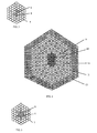
- a cross-section of this package is schematically shown in Fig.1 .
- the core (1) and low refractive claddings (3) were formed from the glass N°9 (Table 2), high refractive claddings (2) from the glass N°2 (Table 2), light absorbing cladding (4) from the glass N°3 (Table 3), protective envelope (5) from the glass N°10 (Table 4).
- the package was re-drawn into a rod with Bragg structure (6) of double apothem 1.18 mm, the cross-section of which is shown in Fig.2 . Then, a secondary hexagonal package of 9.5 mm double apothem was drawn from the rod with Bragg structure (6), and also from rods (7) made of the glass N°10 (Table 4), and electrode capillaries (8). Then, this package was re-drawn into a preform, the cross-section of which is shown in Fig.3 , and then, finally, into a photonic crystal electrooptic fiber with a diameter of 100-200 ⁇ m.
- the rods of circular section 1.10 mm in diameter were drawn from bars of circular section made from the glass N°2 (Table 2) with index 1.86, the glass N°10 (Table 4) with index 1.52, and the glass N°3 (Table 3).
- Lead filled capillaries of 1.10 mm outer diameter were drawn from the lead filled tube made of the glass N°10 (Table 4). From these rods a package of 30 mm double apothem and 400 mm long was produced. Bragg structure supplied with a soft protective envelope was formed in the package.
- the core (1) and low refractive (3) and protective envelope (5) were bundled from the glass N°10 (Table 4), and the light absorbing cladding (4) from the glass N°3 (Table 3).
- the package was re-drawn into a hexagonal rod of double apothem 1.10 mm the cross-section of which is shown in Fig.4 .
- the secondary package of double apothem 8.7 mm was assembled from the produced rods, initial rods of circular section made of the glass N°10 (Table 4) and electrode capillaries were assembled.
- This package was re-drawn into several preforms of double apothem 3-4 mm, after which the preforms were re-drawn into a photonic crystal electrooptic fiber of 100-300 ⁇ m in diameter, 30-60V electric voltage being applied to one of the electrode pairs at the process of drawing.
Landscapes
- Chemical & Material Sciences (AREA)
- Engineering & Computer Science (AREA)
- Organic Chemistry (AREA)
- Physics & Mathematics (AREA)
- Life Sciences & Earth Sciences (AREA)
- Geochemistry & Mineralogy (AREA)
- Materials Engineering (AREA)
- Optics & Photonics (AREA)
- General Life Sciences & Earth Sciences (AREA)
- Manufacturing & Machinery (AREA)
- Chemical Kinetics & Catalysis (AREA)
- Crystallography & Structural Chemistry (AREA)
- General Chemical & Material Sciences (AREA)
- Nonlinear Science (AREA)
- Ceramic Engineering (AREA)
- Dispersion Chemistry (AREA)
- General Physics & Mathematics (AREA)
- Glass Compositions (AREA)
- Manufacture, Treatment Of Glass Fibers (AREA)
- Chemical Or Physical Treatment Of Fibers (AREA)
Claims (15)
- Elektrooptische Faser mit photonischem Kristall, einschließlich ihrer Elementarbestandteile, aus Mehrkomponentengläsern, wobei die Faser aufweist
einen Mittelteil, der eine Bragg-Struktur bildet, wobei der Mittelteil einen Kern (1), der homogen aus einem Glas mit niedrigem Brechungsindex gefertigt ist, und einen vorgestalteten Satz von Mänteln abwechselnd aus Gläsern mit hohem Brechungsindex (2) und Gläsern mit niedrigem Brechungsindex (3) aufweist;
einen Umfangsteil, der eine Hülle für die Bragg-Struktur bildet, wobei der Umfangsteil aus Mehrkomponentengläsern mit einer niedrigen Viskosität im Temperaturbereich des Faserziehens gebildet ist; und Metallelektroden, die entlang der Faserachse angeordnet sind und in dem Umfangsteil angrenzend an den Mittelteil auf sich diametral gegenüberliegenden Seiten eingebettet sind, und eine äußere Polymer-Schutzhülle,wobei die Gläser einen hohen Kerr-Koeffizienten aufweisen. - Faser nach Anspruch 1, wobei die Elemente der Bragg-Struktur einen vorgestalteten Querschnitt aufweisen
- Faser nach Anspruch 1 oder 2, wobei der Kern, die Mäntel mit niedrigem Brechungsindex und die Mäntel mit hohem Brechungsindex aus Gläsern gefertigt sind, die die folgenden Komponenten (in Gew.-%) enthalten: SiO2 (7-25%), B2O3 (6-15%), La2O3 (14-30%), BaO (21-35%), TiO2 (12-15%), ZrO2 (1-6%), WO3 (0,7-2%), Nb2O5 (2,5-11%) und mindestens eine Komponente aus der Gruppe As2O3, Sb2O, in Mengen von 0,1-0,5%
- Faser nach einem der Ansprüche 1 oder 2, wobei die Mäntel mit hohem Brechungsindex aus Gläsern gefertigt sind, die die folgenden Komponenten (in Gew-%) enthalten: SiO2 (7-25%), B2O3 (6-15%), La2O, (14-30%), BaO (21-35%), TiO2 (12-15%), ZrO2 (1-6%), WO3 (0,7-2%), Nb2O5 (2,5-11%) und mindestens eine Komponente aus der Gruppe As2O3, Sb2O3 in Mengen von 0,1-0,5%; und der Kern und die Mäntel mit niedrigem Brechungsindex aus Gläsern gefertigt sind, die die folgenden Komponenten (in Gew.-%) enthalten: SiO2 (50-75%), mindestens eine Komponente der Gruppe B2O3, Al2O3 in Mengen von B2O3 (1-25%), Al2O3 (1-10%), mindestens eine der Komponenten der Gruppe K2O, Na2O, Li2O in Mengen von K2O (1-12%), Na2O (2-20%), Li2O (1-5%), mindestens eine Komponente der Gruppe BaO, CaO, MgO in Mengen von (Gew-%) BaO, CaO (0,5-6%), MgO (0,5-4%) und mindestens eine Komponente der Gruppe As2O3, Sb2O3 in Mengen von 0,1-0,5 Gew-%
- Faser nach einem der Ansprüche 1 bis 4, wobei der Kern und/oder die Mäntel zusätzlich mindestens eine der folgenden Komponenten (in Gew-%) enthalten: SrO, CaO (0,5-2%), Ta2O5 (2,5-11%)
- Faser nach einem der Ansprüche 1 bis 5, wobei das Glas des äußeren Mantels mit niedrigem Brechungsindex der Bragg-Struktur und/oder das Glas des äußeren Mantels mit hohem Brechungsindex der Bragg-Struktur zusätzlich mindestens eine Komponente der Gruppe CoO, Cr2O3, Mn2O3 (in Gew-%) CoO, Cr2O3 (0,1-0,5%), Mn2O3 (0,01-2%) enthält.
- Faser nach einem der Ansprüche 1 bis 6, wobei die Bragg-Struktur-Mäntel einen Querschnitt senkrecht zur Faserachse in Form eines Hexagons aufweisen, das in Richtung einer der Diagonalen verlängert ist, während die Elektroden so angeordnet sind, dass die die Elektrodenpaare verbindende Linie mit dieser Diagonale einen indirekten Winkel bildet
- Faser nach einem der vorhergehenden Ansprüche, wobei die Mäntel mit hohem Brechungsindex unterbrochen sind und Einsätze aus Glas mit niedrigem Brechungsindex enthalten
- Faser nach einem der vorhergehenden Ansprüche, wobei das Glas des Bragg-Struktur-Kerns zusätzlich mindestens eine der folgenden Komponenten in Gew-% enthält. Er2O3, Yb2O3, Nd2O3, Y2O3 (0,0-3%), Tb2O3 (0,01-1,5%)
- Faser nach einem der vorhergehenden Ansprüche, wobei leitfähige Elektroden aus Zinn gefertigt sind
- Faser nach einem der vorhergehenden Ansprüche, wobei leitfähige Elektroden aus einer Zinn-Blei-Legierung gefertigt sind
- Faser nach einem der vorhergehenden Ansprüche, wobei diese zwei Paare von leitfähigen Elektroden enthält, während Elektroden von jedem Paar an sich diametral gegenüberliegenden Seiten an die Bragg-Struktur angrenzen und Ebenen durch Mittelachsen von Elektroden von jedem Elektrodenpaar zusammen vorgestaltete Winkel bilden
- Faser nach einem der vorhergehenden Ansprüche, wobei die Gläser einen Kerr-Koeffizienten von nicht weniger als 5 10-16 m/V 2 aufweisen
- Verfahren zur Herstellung einer elektrooptischen Faser mit photonischem Kristall, umfassend: Herstellen von separaten Ausgangsstäben aus den Stangen, die aus einem Kern und Mantelgläsern gefertigt sind,Ziehen von Stäben mit gleichen Abmessungen und Formen aus diesen,Bündeln eines Pakets von Elementen einer Faser mit Elektroden aus den Stäben, Ziehen des Vorformlings aus dem Paket und Ziehen der Faser,dadurch gekennzeichnet, dass die Anfangsstäbe aus Stangen mit Kern und Mantel aus Glas mit niedrigem Brechungsindex und Stangen mit Mantel aus Glas mit hohem Brechungsindex gezogen werden, woraus ein oder mehrere Pakete mit hexagonalem Querschnitt gebündelt werden, wobei ein Mittelteil eine Bragg-Struktur bildet, in der Glasschichten mit niedrigem Brechungsindex und mit hohem Brechungsindex, die von den Stäben gebildet sind, abwechselnd an einen Glaskern mit niedrigem Brechungsindex angrenzen, und wobei ein Umfangsteil eine Hülle für die Bragg-Struktur bildet, wobei das Umfangsteil durch Stäbe gebildet wird, die aus Gläsern mit einer niedrigen Viskosität im Glaserweichungstemperaturbereich gefertigt sind, das gebündelte Paket gezogen wird, um einen Stab mit Bragg-Struktur zu bilden, Elektrodenstäbe aus mit Metall gefüllten Glasröhren gezogen werden, ein sekundäres Paket gebildet wird und aus einem oder mehreren Stäben mit Bragg-Struktur und einem oder mehreren Elektrodenpaaren entsprechend den vorgestalteten Parametern einer spezifischen Art des Bündels besteht, wobei sich die Stäbe mit der Bragg-Struktur in einem Mittelteil des sekundären Pakets befinden, das von einer oder mehreren Reihen von Stäben aus Glas mit einer niedrigen Viskosität im Temperaturbereich des Faserziehens umgeben ist, um eine weiche Hülle der Faser zu bilden, während die Elektroden nahe der Bragg-Struktur in sich diametral gegenüberliegenden Paaren angeordnet sind, das sekundäre Paket erneut gezogen wird, um einen Vorformling und dann schließlich eine elektrooptische Faser mit photonischem Kristall zu bilden
- Verfahren nach Anspruch 14, wobei beim Vorgang des erneuten Ziehens durch eines der Elektrodenpaare eine elektrische Spannung von mehreren Zehntel Volt an das sekundäre Paket angelegt wird
Applications Claiming Priority (2)
| Application Number | Priority Date | Filing Date | Title |
|---|---|---|---|
| RU2007122610/28A RU2397516C2 (ru) | 2007-06-15 | 2007-06-15 | Фотонно-кристаллическое электрооптическое волокно и способ его изготовления |
| PCT/IB2008/001506 WO2008152479A1 (en) | 2007-06-15 | 2008-06-12 | Photonic crystal electrooptic fiber and method for manufacturing such a fiber |
Publications (2)
| Publication Number | Publication Date |
|---|---|
| EP2165237A1 EP2165237A1 (de) | 2010-03-24 |
| EP2165237B1 true EP2165237B1 (de) | 2010-12-01 |
Family
ID=39848877
Family Applications (1)
| Application Number | Title | Priority Date | Filing Date |
|---|---|---|---|
| EP08762839A Not-in-force EP2165237B1 (de) | 2007-06-15 | 2008-06-12 | Elektrooptische faser mit photonischem kristall und verfahren zur herstellung einer solchen faser |
Country Status (5)
| Country | Link |
|---|---|
| EP (1) | EP2165237B1 (de) |
| AT (1) | ATE490487T1 (de) |
| DE (1) | DE602008003813D1 (de) |
| RU (1) | RU2397516C2 (de) |
| WO (1) | WO2008152479A1 (de) |
Families Citing this family (5)
| Publication number | Priority date | Publication date | Assignee | Title |
|---|---|---|---|---|
| EP2218694A4 (de) * | 2007-10-05 | 2014-03-12 | Olympus Corp | Optisches glas und optische vorrichtung mit dem optischen glas |
| RU2401814C1 (ru) * | 2009-05-29 | 2010-10-20 | Государственное образовательное учреждение высшего профессионального образования "Московский государственный университет путей сообщения" (МИИТ) | Способ изготовления фотонно-кристаллического волокна |
| RU2401813C1 (ru) * | 2009-05-29 | 2010-10-20 | Государственное образовательное учреждение высшего профессионального образования "Московский государственный университет путей сообщения" (МИИТ) | Способ изготовления фотонно-кристаллического волокна |
| US8200055B2 (en) * | 2010-07-19 | 2012-06-12 | Harish Subbaraman | Two-dimensional surface normal slow-light photonic crystal waveguide optical phased array |
| RU2531127C2 (ru) * | 2013-01-10 | 2014-10-20 | Открытое Акционерное Общество "АлМет" | Фотонно-кристаллический волновод для селективного пропускания оптического излучения |
Family Cites Families (6)
| Publication number | Priority date | Publication date | Assignee | Title |
|---|---|---|---|---|
| RU2064459C1 (ru) * | 1993-04-08 | 1996-07-27 | Акционерное общество открытого типа "Лыткаринский завод оптического стекла" | Способ изготовления светопроводящего стекловолокна и устройство для изготовления светопроводящего стекловолокна |
| US5768462A (en) * | 1996-03-05 | 1998-06-16 | Kvh Industries, Inc. | Grooved optical fiber for use with an electrode and a method for making same |
| US6243522B1 (en) * | 1998-12-21 | 2001-06-05 | Corning Incorporated | Photonic crystal fiber |
| US6334017B1 (en) * | 1999-10-26 | 2001-12-25 | Corning Inc | Ring photonic crystal fibers |
| GB2386434A (en) * | 2002-03-13 | 2003-09-17 | Univ Southampton | Microstructured optical fibre fabricated by extrusion through special extruder die |
| RU2247414C2 (ru) * | 2002-03-15 | 2005-02-27 | Федеральное государственное унитарное предприятие "Всероссийский научный центр "Государственный оптический институт им. С.И. Вавилова (ФГУП ГОИ) | Одномодовое электрооптическое волокно и способ его изготовления |
-
2007
- 2007-06-15 RU RU2007122610/28A patent/RU2397516C2/ru active
-
2008
- 2008-06-12 DE DE602008003813T patent/DE602008003813D1/de active Active
- 2008-06-12 WO PCT/IB2008/001506 patent/WO2008152479A1/en not_active Ceased
- 2008-06-12 AT AT08762839T patent/ATE490487T1/de not_active IP Right Cessation
- 2008-06-12 EP EP08762839A patent/EP2165237B1/de not_active Not-in-force
Also Published As
| Publication number | Publication date |
|---|---|
| RU2397516C2 (ru) | 2010-08-20 |
| EP2165237A1 (de) | 2010-03-24 |
| DE602008003813D1 (de) | 2011-01-13 |
| ATE490487T1 (de) | 2010-12-15 |
| RU2007122610A (ru) | 2008-12-20 |
| WO2008152479A1 (en) | 2008-12-18 |
Similar Documents
| Publication | Publication Date | Title |
|---|---|---|
| EP0810453B1 (de) | Artikel mit einer mikrostrukturierten optischen Faser und Verfahren zur Herstellung einer solchen Faser | |
| US5802236A (en) | Article comprising a micro-structured optical fiber, and method of making such fiber | |
| Pysz et al. | Stack and draw fabrication of soft glass microstructured fiber optics | |
| DE60217684T2 (de) | Optische fasern mit hoher numerischer apertur | |
| CN112292358B (zh) | 相干成像光纤以及方法 | |
| US9146345B1 (en) | High power optical fibers | |
| US9971087B2 (en) | High-birefringence hollow-core fibers and techniques for making same | |
| US20100104869A1 (en) | Photonic Crystal Fibers and Methods for Manufacturing the Same | |
| EP4123349A1 (de) | Mehrkernfaser, mehrkernfaserband, mehrkernfaserherstellungsverfahren und mehrkernfaserverarbeitungsverfahren | |
| WO2017002460A1 (ja) | マルチコア偏波保持ファイバ | |
| WO2020210208A1 (en) | Infrared-transmitting, polarization-maintaining optical fiber and method for making | |
| WO2006100488A1 (en) | Multiple core microstructured optical fibre | |
| EP2228673A1 (de) | Optische faser mit bandlücke | |
| WO2008152479A1 (en) | Photonic crystal electrooptic fiber and method for manufacturing such a fiber | |
| JP5676152B2 (ja) | 光ファイバ及びその製造方法 | |
| EP1504304A1 (de) | Mikrostrukturierter optischer wellenleiter mit hoher optischer nichtlinearität | |
| Lu et al. | Single-polarization single-mode photonic crystal fibers with uniformly sized air holes | |
| US20090181842A1 (en) | Polarization-maintaining optical fiber and method for manufacturing the same | |
| RU2247414C2 (ru) | Одномодовое электрооптическое волокно и способ его изготовления | |
| Ballato | Optical fibers | |
| JPWO2022172910A5 (de) | ||
| WO2003093884A2 (en) | A method and apparatus relating to optical fibres | |
| Thavasi Raja et al. | Large mode area modified clad leakage channel fibers with low bending and higher differential losses | |
| US20120321260A1 (en) | Optical waveguides having flattened high order modes | |
| CN107490820A (zh) | 一种全固态大模面积近零色散平坦微结构光纤 |
Legal Events
| Date | Code | Title | Description |
|---|---|---|---|
| PUAI | Public reference made under article 153(3) epc to a published international application that has entered the european phase |
Free format text: ORIGINAL CODE: 0009012 |
|
| 17P | Request for examination filed |
Effective date: 20091215 |
|
| AK | Designated contracting states |
Kind code of ref document: A1 Designated state(s): AT BE BG CH CY CZ DE DK EE ES FI FR GB GR HR HU IE IS IT LI LT LU LV MC MT NL NO PL PT RO SE SI SK TR |
|
| AX | Request for extension of the european patent |
Extension state: AL BA MK RS |
|
| DAX | Request for extension of the european patent (deleted) | ||
| GRAP | Despatch of communication of intention to grant a patent |
Free format text: ORIGINAL CODE: EPIDOSNIGR1 |
|
| RIN1 | Information on inventor provided before grant (corrected) |
Inventor name: POLUKHIN, VLADIMIR NIKOLAEVICH Inventor name: TAGANTSEV, DMITRY KIRILLOVICH Inventor name: ZHELTOV, VALERII BORISOVICH Inventor name: LIPOVSKII, ANDREY ALEKSANDROVICH Inventor name: KOBELKE, JENS Inventor name: BARTELT, HARTMUT Inventor name: IVANOV, VLADIMIR NIKOLAEVICH Inventor name: ANAN'EV, ANATOLII VLADIMOROVICH Inventor name: TATARINTSEV, BORIS VASIL'EVICH |
|
| GRAS | Grant fee paid |
Free format text: ORIGINAL CODE: EPIDOSNIGR3 |
|
| GRAA | (expected) grant |
Free format text: ORIGINAL CODE: 0009210 |
|
| AK | Designated contracting states |
Kind code of ref document: B1 Designated state(s): AT BE BG CH CY CZ DE DK EE ES FI FR GB GR HR HU IE IS IT LI LT LU LV MC MT NL NO PL PT RO SE SI SK TR |
|
| REG | Reference to a national code |
Ref country code: GB Ref legal event code: FG4D |
|
| REG | Reference to a national code |
Ref country code: CH Ref legal event code: EP |
|
| REG | Reference to a national code |
Ref country code: IE Ref legal event code: FG4D |
|
| REF | Corresponds to: |
Ref document number: 602008003813 Country of ref document: DE Date of ref document: 20110113 Kind code of ref document: P |
|
| REG | Reference to a national code |
Ref country code: NL Ref legal event code: VDEP Effective date: 20101201 |
|
| PG25 | Lapsed in a contracting state [announced via postgrant information from national office to epo] |
Ref country code: LT Free format text: LAPSE BECAUSE OF FAILURE TO SUBMIT A TRANSLATION OF THE DESCRIPTION OR TO PAY THE FEE WITHIN THE PRESCRIBED TIME-LIMIT Effective date: 20101201 Ref country code: NO Free format text: LAPSE BECAUSE OF FAILURE TO SUBMIT A TRANSLATION OF THE DESCRIPTION OR TO PAY THE FEE WITHIN THE PRESCRIBED TIME-LIMIT Effective date: 20110301 |
|
| LTIE | Lt: invalidation of european patent or patent extension |
Effective date: 20101201 |
|
| PG25 | Lapsed in a contracting state [announced via postgrant information from national office to epo] |
Ref country code: CY Free format text: LAPSE BECAUSE OF FAILURE TO SUBMIT A TRANSLATION OF THE DESCRIPTION OR TO PAY THE FEE WITHIN THE PRESCRIBED TIME-LIMIT Effective date: 20101201 Ref country code: NL Free format text: LAPSE BECAUSE OF FAILURE TO SUBMIT A TRANSLATION OF THE DESCRIPTION OR TO PAY THE FEE WITHIN THE PRESCRIBED TIME-LIMIT Effective date: 20101201 Ref country code: AT Free format text: LAPSE BECAUSE OF FAILURE TO SUBMIT A TRANSLATION OF THE DESCRIPTION OR TO PAY THE FEE WITHIN THE PRESCRIBED TIME-LIMIT Effective date: 20101201 Ref country code: LV Free format text: LAPSE BECAUSE OF FAILURE TO SUBMIT A TRANSLATION OF THE DESCRIPTION OR TO PAY THE FEE WITHIN THE PRESCRIBED TIME-LIMIT Effective date: 20101201 Ref country code: BG Free format text: LAPSE BECAUSE OF FAILURE TO SUBMIT A TRANSLATION OF THE DESCRIPTION OR TO PAY THE FEE WITHIN THE PRESCRIBED TIME-LIMIT Effective date: 20110301 Ref country code: SI Free format text: LAPSE BECAUSE OF FAILURE TO SUBMIT A TRANSLATION OF THE DESCRIPTION OR TO PAY THE FEE WITHIN THE PRESCRIBED TIME-LIMIT Effective date: 20101201 Ref country code: SE Free format text: LAPSE BECAUSE OF FAILURE TO SUBMIT A TRANSLATION OF THE DESCRIPTION OR TO PAY THE FEE WITHIN THE PRESCRIBED TIME-LIMIT Effective date: 20101201 Ref country code: FI Free format text: LAPSE BECAUSE OF FAILURE TO SUBMIT A TRANSLATION OF THE DESCRIPTION OR TO PAY THE FEE WITHIN THE PRESCRIBED TIME-LIMIT Effective date: 20101201 Ref country code: HR Free format text: LAPSE BECAUSE OF FAILURE TO SUBMIT A TRANSLATION OF THE DESCRIPTION OR TO PAY THE FEE WITHIN THE PRESCRIBED TIME-LIMIT Effective date: 20101201 |
|
| PG25 | Lapsed in a contracting state [announced via postgrant information from national office to epo] |
Ref country code: GR Free format text: LAPSE BECAUSE OF FAILURE TO SUBMIT A TRANSLATION OF THE DESCRIPTION OR TO PAY THE FEE WITHIN THE PRESCRIBED TIME-LIMIT Effective date: 20110302 |
|
| PG25 | Lapsed in a contracting state [announced via postgrant information from national office to epo] |
Ref country code: PT Free format text: LAPSE BECAUSE OF FAILURE TO SUBMIT A TRANSLATION OF THE DESCRIPTION OR TO PAY THE FEE WITHIN THE PRESCRIBED TIME-LIMIT Effective date: 20110401 Ref country code: BE Free format text: LAPSE BECAUSE OF FAILURE TO SUBMIT A TRANSLATION OF THE DESCRIPTION OR TO PAY THE FEE WITHIN THE PRESCRIBED TIME-LIMIT Effective date: 20101201 Ref country code: IS Free format text: LAPSE BECAUSE OF FAILURE TO SUBMIT A TRANSLATION OF THE DESCRIPTION OR TO PAY THE FEE WITHIN THE PRESCRIBED TIME-LIMIT Effective date: 20110401 Ref country code: CZ Free format text: LAPSE BECAUSE OF FAILURE TO SUBMIT A TRANSLATION OF THE DESCRIPTION OR TO PAY THE FEE WITHIN THE PRESCRIBED TIME-LIMIT Effective date: 20101201 Ref country code: EE Free format text: LAPSE BECAUSE OF FAILURE TO SUBMIT A TRANSLATION OF THE DESCRIPTION OR TO PAY THE FEE WITHIN THE PRESCRIBED TIME-LIMIT Effective date: 20101201 Ref country code: ES Free format text: LAPSE BECAUSE OF FAILURE TO SUBMIT A TRANSLATION OF THE DESCRIPTION OR TO PAY THE FEE WITHIN THE PRESCRIBED TIME-LIMIT Effective date: 20110312 |
|
| PG25 | Lapsed in a contracting state [announced via postgrant information from national office to epo] |
Ref country code: PL Free format text: LAPSE BECAUSE OF FAILURE TO SUBMIT A TRANSLATION OF THE DESCRIPTION OR TO PAY THE FEE WITHIN THE PRESCRIBED TIME-LIMIT Effective date: 20101201 Ref country code: SK Free format text: LAPSE BECAUSE OF FAILURE TO SUBMIT A TRANSLATION OF THE DESCRIPTION OR TO PAY THE FEE WITHIN THE PRESCRIBED TIME-LIMIT Effective date: 20101201 Ref country code: RO Free format text: LAPSE BECAUSE OF FAILURE TO SUBMIT A TRANSLATION OF THE DESCRIPTION OR TO PAY THE FEE WITHIN THE PRESCRIBED TIME-LIMIT Effective date: 20101201 |
|
| PLBE | No opposition filed within time limit |
Free format text: ORIGINAL CODE: 0009261 |
|
| STAA | Information on the status of an ep patent application or granted ep patent |
Free format text: STATUS: NO OPPOSITION FILED WITHIN TIME LIMIT |
|
| PG25 | Lapsed in a contracting state [announced via postgrant information from national office to epo] |
Ref country code: DK Free format text: LAPSE BECAUSE OF FAILURE TO SUBMIT A TRANSLATION OF THE DESCRIPTION OR TO PAY THE FEE WITHIN THE PRESCRIBED TIME-LIMIT Effective date: 20101201 |
|
| 26N | No opposition filed |
Effective date: 20110902 |
|
| REG | Reference to a national code |
Ref country code: DE Ref legal event code: R097 Ref document number: 602008003813 Country of ref document: DE Effective date: 20110902 |
|
| PG25 | Lapsed in a contracting state [announced via postgrant information from national office to epo] |
Ref country code: MT Free format text: LAPSE BECAUSE OF FAILURE TO SUBMIT A TRANSLATION OF THE DESCRIPTION OR TO PAY THE FEE WITHIN THE PRESCRIBED TIME-LIMIT Effective date: 20101201 |
|
| REG | Reference to a national code |
Ref country code: IE Ref legal event code: MM4A |
|
| PG25 | Lapsed in a contracting state [announced via postgrant information from national office to epo] |
Ref country code: IE Free format text: LAPSE BECAUSE OF NON-PAYMENT OF DUE FEES Effective date: 20110612 |
|
| REG | Reference to a national code |
Ref country code: CH Ref legal event code: PL |
|
| REG | Reference to a national code |
Ref country code: CH Ref legal event code: PL |
|
| PG25 | Lapsed in a contracting state [announced via postgrant information from national office to epo] |
Ref country code: LI Free format text: LAPSE BECAUSE OF NON-PAYMENT OF DUE FEES Effective date: 20120630 Ref country code: MC Free format text: LAPSE BECAUSE OF NON-PAYMENT OF DUE FEES Effective date: 20110630 Ref country code: CH Free format text: LAPSE BECAUSE OF NON-PAYMENT OF DUE FEES Effective date: 20120630 |
|
| PG25 | Lapsed in a contracting state [announced via postgrant information from national office to epo] |
Ref country code: LU Free format text: LAPSE BECAUSE OF NON-PAYMENT OF DUE FEES Effective date: 20110612 |
|
| PG25 | Lapsed in a contracting state [announced via postgrant information from national office to epo] |
Ref country code: TR Free format text: LAPSE BECAUSE OF FAILURE TO SUBMIT A TRANSLATION OF THE DESCRIPTION OR TO PAY THE FEE WITHIN THE PRESCRIBED TIME-LIMIT Effective date: 20101201 |
|
| PG25 | Lapsed in a contracting state [announced via postgrant information from national office to epo] |
Ref country code: HU Free format text: LAPSE BECAUSE OF FAILURE TO SUBMIT A TRANSLATION OF THE DESCRIPTION OR TO PAY THE FEE WITHIN THE PRESCRIBED TIME-LIMIT Effective date: 20101201 |
|
| REG | Reference to a national code |
Ref country code: FR Ref legal event code: PLFP Year of fee payment: 9 |
|
| PGFP | Annual fee paid to national office [announced via postgrant information from national office to epo] |
Ref country code: IT Payment date: 20160831 Year of fee payment: 9 Ref country code: DE Payment date: 20160830 Year of fee payment: 9 Ref country code: GB Payment date: 20160831 Year of fee payment: 9 |
|
| REG | Reference to a national code |
Ref country code: DE Ref legal event code: R082 Ref document number: 602008003813 Country of ref document: DE |
|
| PGFP | Annual fee paid to national office [announced via postgrant information from national office to epo] |
Ref country code: FR Payment date: 20160829 Year of fee payment: 9 |
|
| REG | Reference to a national code |
Ref country code: DE Ref legal event code: R119 Ref document number: 602008003813 Country of ref document: DE |
|
| GBPC | Gb: european patent ceased through non-payment of renewal fee |
Effective date: 20170612 |
|
| REG | Reference to a national code |
Ref country code: FR Ref legal event code: ST Effective date: 20180228 |
|
| PG25 | Lapsed in a contracting state [announced via postgrant information from national office to epo] |
Ref country code: DE Free format text: LAPSE BECAUSE OF NON-PAYMENT OF DUE FEES Effective date: 20180103 Ref country code: GB Free format text: LAPSE BECAUSE OF NON-PAYMENT OF DUE FEES Effective date: 20170612 |
|
| PG25 | Lapsed in a contracting state [announced via postgrant information from national office to epo] |
Ref country code: IT Free format text: LAPSE BECAUSE OF NON-PAYMENT OF DUE FEES Effective date: 20170612 Ref country code: FR Free format text: LAPSE BECAUSE OF NON-PAYMENT OF DUE FEES Effective date: 20170630 |